DE102018127969A1 - Measuring and positioning methods as well as arrangements for the assembly of an electrical cable - Google Patents
Measuring and positioning methods as well as arrangements for the assembly of an electrical cableDownload PDFInfo
- Publication number
- DE102018127969A1 DE102018127969A1DE102018127969.8ADE102018127969ADE102018127969A1DE 102018127969 A1DE102018127969 A1DE 102018127969A1DE 102018127969 ADE102018127969 ADE 102018127969ADE 102018127969 A1DE102018127969 A1DE 102018127969A1
- Authority
- DE
- Germany
- Prior art keywords
- conductor part
- cable
- inner conductor
- outer conductor
- support sleeve
- Prior art date
- Legal status (The legal status is an assumption and is not a legal conclusion. Google has not performed a legal analysis and makes no representation as to the accuracy of the status listed.)
- Pending
Links
Images


Classifications
- H—ELECTRICITY
- H01—ELECTRIC ELEMENTS
- H01R—ELECTRICALLY-CONDUCTIVE CONNECTIONS; STRUCTURAL ASSOCIATIONS OF A PLURALITY OF MUTUALLY-INSULATED ELECTRICAL CONNECTING ELEMENTS; COUPLING DEVICES; CURRENT COLLECTORS
- H01R43/00—Apparatus or processes specially adapted for manufacturing, assembling, maintaining, or repairing of line connectors or current collectors or for joining electric conductors
- H01R43/20—Apparatus or processes specially adapted for manufacturing, assembling, maintaining, or repairing of line connectors or current collectors or for joining electric conductors for assembling or disassembling contact members with insulating base, case or sleeve
- G—PHYSICS
- G01—MEASURING; TESTING
- G01B—MEASURING LENGTH, THICKNESS OR SIMILAR LINEAR DIMENSIONS; MEASURING ANGLES; MEASURING AREAS; MEASURING IRREGULARITIES OF SURFACES OR CONTOURS
- G01B11/00—Measuring arrangements characterised by the use of optical techniques
- G01B11/14—Measuring arrangements characterised by the use of optical techniques for measuring distance or clearance between spaced objects or spaced apertures
- G—PHYSICS
- G01—MEASURING; TESTING
- G01B—MEASURING LENGTH, THICKNESS OR SIMILAR LINEAR DIMENSIONS; MEASURING ANGLES; MEASURING AREAS; MEASURING IRREGULARITIES OF SURFACES OR CONTOURS
- G01B7/00—Measuring arrangements characterised by the use of electric or magnetic techniques
- G01B7/14—Measuring arrangements characterised by the use of electric or magnetic techniques for measuring distance or clearance between spaced objects or spaced apertures
- H—ELECTRICITY
- H01—ELECTRIC ELEMENTS
- H01B—CABLES; CONDUCTORS; INSULATORS; SELECTION OF MATERIALS FOR THEIR CONDUCTIVE, INSULATING OR DIELECTRIC PROPERTIES
- H01B13/00—Apparatus or processes specially adapted for manufacturing conductors or cables
- H01B13/0003—Apparatus or processes specially adapted for manufacturing conductors or cables for feeding conductors or cables
- H—ELECTRICITY
- H01—ELECTRIC ELEMENTS
- H01R—ELECTRICALLY-CONDUCTIVE CONNECTIONS; STRUCTURAL ASSOCIATIONS OF A PLURALITY OF MUTUALLY-INSULATED ELECTRICAL CONNECTING ELEMENTS; COUPLING DEVICES; CURRENT COLLECTORS
- H01R43/00—Apparatus or processes specially adapted for manufacturing, assembling, maintaining, or repairing of line connectors or current collectors or for joining electric conductors
- H01R43/04—Apparatus or processes specially adapted for manufacturing, assembling, maintaining, or repairing of line connectors or current collectors or for joining electric conductors for forming connections by deformation, e.g. crimping tool
- H01R43/048—Crimping apparatus or processes
- H01R43/052—Crimping apparatus or processes with wire-feeding mechanism
- H—ELECTRICITY
- H01—ELECTRIC ELEMENTS
- H01R—ELECTRICALLY-CONDUCTIVE CONNECTIONS; STRUCTURAL ASSOCIATIONS OF A PLURALITY OF MUTUALLY-INSULATED ELECTRICAL CONNECTING ELEMENTS; COUPLING DEVICES; CURRENT COLLECTORS
- H01R9/00—Structural associations of a plurality of mutually-insulated electrical connecting elements, e.g. terminal strips or terminal blocks; Terminals or binding posts mounted upon a base or in a case; Bases therefor
- H01R9/03—Connectors arranged to contact a plurality of the conductors of a multiconductor cable, e.g. tapping connections
- H01R9/05—Connectors arranged to contact a plurality of the conductors of a multiconductor cable, e.g. tapping connections for coaxial cables
- H01R9/0518—Connection to outer conductor by crimping or by crimping ferrule
- H—ELECTRICITY
- H01—ELECTRIC ELEMENTS
- H01R—ELECTRICALLY-CONDUCTIVE CONNECTIONS; STRUCTURAL ASSOCIATIONS OF A PLURALITY OF MUTUALLY-INSULATED ELECTRICAL CONNECTING ELEMENTS; COUPLING DEVICES; CURRENT COLLECTORS
- H01R24/00—Two-part coupling devices, or either of their cooperating parts, characterised by their overall structure
- H01R24/38—Two-part coupling devices, or either of their cooperating parts, characterised by their overall structure having concentrically or coaxially arranged contacts
- H01R24/40—Two-part coupling devices, or either of their cooperating parts, characterised by their overall structure having concentrically or coaxially arranged contacts specially adapted for high frequency
Landscapes
- Engineering & Computer Science (AREA)
- Manufacturing & Machinery (AREA)
- Physics & Mathematics (AREA)
- General Physics & Mathematics (AREA)
- Manufacturing Of Electrical Connectors (AREA)
Abstract
Translated fromGermanDescription
Translated fromGermanDie Erfindung betrifft ein Messverfahren für die Konfektionierung eines elektrischen Kabels. Die Erfindung betrifft außerdem eine Messanordnung für die Konfektionierung eines elektrischen Kabels. Die Erfindung betrifft ferner eine Referenzeinrichtung für eine Messanordnung sowie ein Computerprogrammprodukt mit Programmcodemitteln zur Ausführung eines Messverfahrens.The invention relates to a measuring method for the assembly of an electrical cable. The invention also relates to a measuring arrangement for the assembly of an electrical cable. The invention further relates to a reference device for a measuring arrangement and a computer program product with program code means for executing a measuring method.
Die Erfindung betrifft auch ein Positionierungsverfahren für die Konfektionierung eines elektrischen Kabels nach dem Oberbegriff des Anspruchs 21. Die Erfindung betrifft außerdem eine Positionierungsanordnung für die Konfektionierung eines elektrischen Kabels gemäß dem Oberbegriff des Anspruchs 31. Die Erfindung betrifft ferner ein Computerprogrammprodukt mit Programmcodemitteln zur Ausführung eines Positionieru ngsverfah rens.The invention also relates to a positioning method for the assembly of an electrical cable according to the preamble of
Schließlich betrifft die Erfindung auch ein Konfektionierungsverfahren und eine Konfektionierungsanordnung für die Konfektionierung eines elektrischen Kabels.Finally, the invention also relates to an assembly method and an assembly arrangement for the assembly of an electrical cable.
Bei der Konfektionierung von elektrischen Kabeln werden deren Leiter typischerweise mit einem Steckverbinder verbunden. Bei dem Steckverbinder kann es sich um einen Stecker, einen Einbaustecker, eine Buchse, einen Kuppler oder einen Adapter handeln. Die im Rahmen der Erfindung verwendete Bezeichnung Steckverbinder steht stellvertretend für alle Varianten.When assembling electrical cables, their conductors are typically connected with a connector. The connector can be a plug, a built-in plug, a socket, a coupler or an adapter. The term connector used in the context of the invention represents all variants.
Ein Steckverbinder dient dazu, eine elektrische Verbindung mit einem entsprechend komplementären weiteren Steckverbinder herzustellen.A connector is used to establish an electrical connection with a correspondingly complementary additional connector.
Insbesondere an Steckverbinder für die Automobilindustrie bzw. für Fahrzeuge werden hohe Anforderungen an die Robustheit und Sicherheit der Steckverbindung gestellt. So muss eine Steckverbindung mitunter hohen Belastungen, beispielsweise mechanischen Belastungen oder thermischen Belastungen, standhalten sowie definiert geschlossen bleiben, so dass die elektrische Verbindung nicht unbeabsichtigt, beispielsweise während des Betriebs eines Fahrzeugs, getrennt wird. Insbesondere beim (teil)autonomen Betrieb von Fahrzeugen und für Assistenzsysteme ist die Gewährleistung der Sicherheit vorrangig.In particular for connectors for the automotive industry and for vehicles, high demands are placed on the robustness and safety of the plug connection. For example, a plug connection must sometimes withstand high loads, for example mechanical loads or thermal loads, and must remain closed in a defined manner, so that the electrical connection is not inadvertently disconnected, for example during the operation of a vehicle. Ensuring safety is a priority, especially in the (partially) autonomous operation of vehicles and for assistance systems.
Weiterhin sind die Anforderungen an Steckverbinder und Kabelverbindungen, insbesondere auch innerhalb eines Fahrzeugs, bezüglich der erforderlichen Datenrate mittlerweile sehr hoch. Mitunter müssen beispielsweise beim autonomen Betrieb eines Fahrzeugs bzw. bei Verwendung von Assistenzsystemen hohe Datenmengen von mehreren Kameras, diversen Sensoren und Navigationsquellen miteinander kombiniert und transportiert werden, üblicherweise in Echtzeit. Der Betrieb vieler Geräte, Bildschirme und Kameras erfordert demnach eine leistungsfähige Infrastruktur in der Fahrzeugelektronik.Furthermore, the demands on connectors and cable connections, especially within a vehicle, regarding the required data rate are now very high. Sometimes, for example, when autonomously operating a vehicle or when using assistance systems, large amounts of data from several cameras, various sensors and navigation sources have to be combined and transported, usually in real time. The operation of many devices, screens and cameras therefore requires a powerful infrastructure in vehicle electronics.
Neben den genannten mechanischen und elektrischen Anforderungen ist es gleichzeitig - zur Einsparung von Bauraum und Gewicht - wichtig, die Steckverbinder möglichst kompakt auszubilden. Bei der Konfektionierung von Kabeln und bei der Herstellung der Komponenten der Steckverbindung ist das Einhaltung der insgesamt erforderlichen Toleranzbereiche in Folge vergleichsweise anspruchsvoll.In addition to the mechanical and electrical requirements mentioned, it is also important - in order to save installation space and weight - to make the connectors as compact as possible. When assembling cables and when manufacturing the components of the plug connection, compliance with the overall required tolerance ranges is comparatively demanding as a result.
Bei der Konfektionierung eines Kabels wird u. a. eine Stützhülse auf das Kabel gecrimpt. Ferner wird ein Innenleiter-Kontaktelement (Innenleiterteil) auf den Innenleiter des Kabels gecrimpt. Aufgrund von Ungenauigkeiten bzw. Toleranzen in diesen Montageschritten ist der Abstand zwischen dem steckerseitigen Ende des Innenleiterteils (d. h. dem vorderen, freien Ende des Innenleiterteils bzw. dem einem Gegensteckverbinder zugewandten Ende des Innenleiterteils) und einem dem Innenleiterteil zugewandten, vorderen (steckerseitigen) Ende der Stützhülse zwischen einzelnen vorkonfektionierten Kabeln verschieden. Insbesondere aufgrund der vorstehend genannten hohen mechanischen und elektrischen Anforderungen an die Steckverbindung müssen entsprechende Abmaße von einem Idealmaß in einen vorgegebenen Toleranzbereichs fallen, um eine ausreichend hohe Qualität der späteren Steckverbindung zu sicherzustellen.When assembling a cable, u. a. a support sleeve crimped onto the cable. Furthermore, an inner conductor contact element (inner conductor part) is crimped onto the inner conductor of the cable. Due to inaccuracies or tolerances in these assembly steps, the distance between the plug-side end of the inner conductor part (i.e. the front, free end of the inner conductor part or the end of the inner conductor part facing a mating connector) and a front (plug-side) end of the support sleeve facing the inner conductor part different between individual pre-assembled cables. In particular due to the above-mentioned high mechanical and electrical requirements for the plug connection, corresponding dimensions have to fall from an ideal dimension into a predetermined tolerance range in order to ensure a sufficiently high quality of the subsequent plug connection.
Gegebenenfalls sind von der Vorgabe abweichende, vorkonfektionierte Kabel oder auch bereits fertig konfektionierte Kabel aus der Fertigungslinie bzw. der Produktion zu entfernen. Die hohen Anforderungen an die Steckverbindungen können somit im Rahmen einer Massenfertigung die Produktionskosten insgesamt in die Höhe treiben.If necessary, pre-assembled cables that deviate from the specification or even pre-assembled cables must be removed from the production line or production. The high demands on the plug connections can thus drive up the overall production costs in the context of mass production.
Der vorliegenden Erfindung liegt damit die Aufgabe zugrunde, die bei der Konfektionierung eines elektrischen Kabels auftretenden Verarbeitungstoleranzen zu reduzieren, insbesondere eine schwankende Konfektionierungsqualität zu vermeiden.The present invention is therefore based on the object of reducing the processing tolerances that occur during the assembly of an electrical cable, in particular to avoid a fluctuating assembly quality.
Diese Aufgabe wird im Rahmen eines Messverfahrens durch Anspruch 1 gelöst. Außerdem wird die Aufgabe durch eine Messanordnung gemäß Anspruch 13 gelöst. Die Aufgabe wird ferner durch eine Referenzeinrichtung nach Anspruch 19 und im Rahmen eines Computerprogrammprodukts mit den Merkmalen des Anspruchs 20 gelöst.This object is achieved within the scope of a measuring method by
Die Aufgabe wird außerdem im Rahmen eines Positionierungsverfahrens durch Anspruch 21 gelöst. Ferner wird die Aufgabe durch eine Positionierungsanordnung gemäß Anspruch 31 gelöst. Außerdem wird die Aufgabe im Rahmen eines Computerprogrammprodukts mit den Merkmalen des Anspruchs 34 gelöst.The task is also performed within the scope of a positioning process by
Die Aufgabe wird schließlich auch durch ein Konfektionierungsverfahren für die Konfektionierung eines elektrischen Kabels mit den Merkmalen des Anspruchs 35 und durch eine Konfektionierungsanordnung für die Konfektionierung eines elektrischen Kabels durch Anspruch 36 gelöst.Finally, the object is also achieved by a manufacturing method for the manufacturing of an electrical cable with the features of claim 35 and by a manufacturing arrangement for the manufacturing of an electrical cable by claim 36.
Die abhängigen Ansprüche betreffen vorteilhafte Ausführungsformen und Varianten der Erfindung.The dependent claims relate to advantageous embodiments and variants of the invention.
Es ist ein Messverfahren für die Konfektionierung eines elektrischen Kabels vorgesehen, wonach ein stirnseitiges Ende einer auf dem Kabel befestigten Stützhülse in Anschlag mit einem Referenzanschlag einer Referenzeinrichtung gebracht wird.A measuring method is provided for the assembly of an electrical cable, according to which an end face of a support sleeve fastened to the cable is brought into abutment with a reference abutment of a reference device.
Die Stützhülse kann in Anschlag mit dem Referenzanschlag gebracht werden, indem das elektrische Kabel und die Referenzeinrichtung relativ zueinander bewegt werden. Die Stützhülse kann somit in Richtung auf den Referenzanschlag zubewegt werden, indem das Kabel und/oder indem die Referenzeinrichtung bewegt wird. Vorzugsweise wird lediglich das elektrische Kabel entlang einer Vorschubrichtung bewegt, während die Referenzeinrichtung stillsteht. Insbesondere ist aber auch eine Ausgestaltung, bei der das Kabel stillsteht und lediglich die Referenzeinrichtung auf das Kabel zubewegt wird, möglich.The support sleeve can be brought into abutment with the reference abutment by moving the electrical cable and the reference device relative to one another. The support sleeve can thus be moved in the direction of the reference stop by moving the cable and / or by moving the reference device. Preferably, only the electrical cable is moved along a feed direction while the reference device is stationary. In particular, however, an embodiment is also possible in which the cable stands still and only the reference device is moved towards the cable.
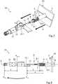
Erfindungsgemäß wird ein axialer Abstand eines vorderen, freien Endes eines auf einem Innenleiter des Kabels befestigten Innenleiterteils von dem Referenzanschlag erfasst und daraus ein Anschlussabstand zwischen dem vorderen, freien Ende des Innenleiterteils und einem, dem Innenleiterteil zugewandten, vorderen Ende der Stützhülse abgeleitet.According to the invention, an axial distance of a front, free end of an inner conductor part fastened on an inner conductor of the cable is detected by the reference stop and a connection distance between the front, free end of the inner conductor part and a front end of the support sleeve facing the inner conductor part is derived therefrom.
Insofern im Rahmen der Beschreibung oder der Patentansprüche auf die Angabe „vorne“ (zum Beispiel „vorderes Ende“) Bezug genommen wird, so ist diese Richtungsangabe auf das „steckerseitige Ende“ bzw. das „freie Ende“ des vorkonfektionierten elektrischen Kabels bezogen, das bei einer später geschlossenen Steckverbindung einem Gegensteckverbinder zugewandt ist. In den nachfolgenden Figuren bezieht sich die Richtungsangabe „vorne“ also jeweils auf das linke Ende des vorkonfektionierten Kabels. Die Richtungsangabe „hinten“ (zum Beispiel „hinteres Ende“) bezieht sich dementsprechend auf die dem steckerseitigen bzw. freien Ende abgewandte Kabelseite, d. h. auf das „kabelseitige Ende“ des vorkonfektionierten elektrischen Kabels; in den nachfolgenden Figuren also jeweils auf die rechte Seite des vorkonfektionierten Kabels.Insofar as reference is made to the “front” (for example “front end”) in the description or the claims, this directional information relates to the “plug end” or the “free end” of the pre-assembled electrical cable, the facing a mating connector in a later closed connector. In the following figures, the “front” direction refers to the left end of the pre-assembled cable. The directional indication "rear" (for example "rear end") accordingly refers to the cable side facing away from the plug-side or free end, ie. H. on the "cable end" of the pre-assembled electrical cable; in the following figures on the right side of the pre-assembled cable.
Bei dem erfindungsgemäßen Innenleiterteil handelt es sich um das innere Kontaktelement des auf dem elektrischen Kabel zu montierenden Steckverbinders. Grundsätzlich kann im Rahmen der Erfindung auch vorgesehen sein, dass ein elektrisches Kabel mit mehreren, z. B. parallel geführten Innenleitern, mit mehreren Innenleiterteilen konfektioniert wird. Vorzugsweise betrifft die Erfindung allerdings die Konfektionierung eines Koaxialkabels, das lediglich einen einzigen Innenleiter aufweist, der elektrisch isoliert innerhalb eines Außenleiters, beispielsweise innerhalb eines Außenleiterschirms, geführt wird.The inner conductor part according to the invention is the inner contact element of the connector to be mounted on the electrical cable. Basically, it can also be provided in the context of the invention that an electrical cable with several, for. B. parallel inner conductors, is assembled with several inner conductor parts. However, the invention preferably relates to the assembly of a coaxial cable which has only a single inner conductor which is guided in an electrically insulated manner within an outer conductor, for example within an outer conductor shield.
Bei dem Anschlussabstand, der erfindungsgemäß für ein zu konfektionierendes elektrisches Kabel ermittelt bzw. abgeleitet werden kann, handelt es sich um ein besonders relevantes Maß für die Montage des Steckverbinders auf das vorkonfektionierte Kabel. Der Anschlussabstand kann insbesondere relevant bei der Positionierung und Befestigung des Innenleiterteils innerhalb eines Außenleiterteils des späteren Steckverbinders sein. Das Außenleiterteil kann auch als Außenleiter-Kontaktelement oder als Steckerkörper bezeichnet werden. Auf Grundlage des Anschlussabstands können sich außerdem noch weitere relevante Maße und Abstände für die Konfektionierung des elektrischen Kabels ableiten lassen.The connection distance, which according to the invention can be determined or derived for an electrical cable to be assembled, is a particularly relevant measure for the assembly of the plug connector on the pre-assembled cable. The connection spacing can be particularly relevant when positioning and fastening the inner conductor part within an outer conductor part of the later connector. The outer conductor part can also be referred to as an outer conductor contact element or as a plug body. On the basis of the connection distance, other relevant dimensions and distances for the assembly of the electrical cable can also be derived.
Im Rahmen der Erfindung kann ein Abmaß von einem Idealmaß des Anschlussabstand für jedes zu konfektionierende elektrische Kabel ermittelt werden. Das ermittelte Abmaß kann für die anschließende Montage eines Steckverbinders oder deren Komponenten, beispielsweise eines Außenleiterteils, anschließend vorteilhaft berücksichtigt werden. Insbesondere kann in Folge ein Außenleiterteil, beispielsweise eine „Außenleiter-Crimphülse“ des Steckverbinders, optimal zur Stützhülse des vorkonfektionierten Kabels axial positioniert werden. Die Stützhülse kann beispielsweise passgenau an eine innenseitige Schulter des Außenleiterteils positioniert und gefügt werden.Within the scope of the invention, a dimension of an ideal dimension of the connection distance can be determined for each electrical cable to be assembled. The determined dimension can then advantageously be taken into account for the subsequent assembly of a connector or its components, for example an outer conductor part. In particular, an outer conductor part, for example an “outer conductor crimp sleeve” of the plug connector, can be optimally positioned axially to the support sleeve of the pre-assembled cable. The support sleeve can, for example, be positioned and fitted precisely on an inside shoulder of the outer conductor part.
Durch die optimale Positionierung des Steckverbinders oder dessen Komponenten auf Grundlage des erfindungsgemäß ermittelten Anschlussabstands kann die Impedanzanpassung von Übergängen zwischen dem Kabel und dem Steckverbinder optimiert werden. Ein einen Impedanzsprung und somit Reflexionen bei der Datenübertragung auslösender Luftspalt kann vermieden werden.The impedance matching of transitions between the cable and the connector can be optimized by the optimal positioning of the connector or its components on the basis of the connection distance determined according to the invention. An air gap triggering an impedance jump and thus reflections during data transmission can be avoided.
Auf Grundlage des ermittelten Anschlussabstands kann also eine hochgenaue Positionierung der Komponenten eines Steckverbinders relativ zueinander bei der Konfektionierung eines Kabels ermöglicht und schwankende Qualität bei der Fertigung vermieden werden. Hierdurch können insbesondere auch die elektrischen Eigenschaften der konfektionierten Kabel, insbesondere deren Eignung für die Hochfrequenztechnik, verbessert sein.Based on the determined connection distance, a highly precise positioning of the components of a connector relative to one another can thus be made possible when assembling a cable and fluctuating quality during production be avoided. As a result, in particular the electrical properties of the assembled cables, in particular their suitability for high-frequency technology, can also be improved.
Schließlich kann durch die Reduzierung von Fehlproduktionen bzw. von Ausschussware die Wirtschaftlichkeit eines Konfektionierungsverfahrens für elektrische Kabel verbessert sein, insbesondere im Rahmen einer Massenproduktion.Finally, by reducing the number of faulty productions or rejects, the cost-effectiveness of a manufacturing process for electrical cables can be improved, particularly in the context of mass production.
Zusätzlich kann es erfindungsgemäß möglich sein, die Verarbeitungsgeschwindigkeit bei der Vorkonfektionierung eines elektrischen Kabels zu erhöhen, da ein gegebenenfalls durch die Beschleunigung der Bearbeitung vergrößertes Toleranzmaß aufgrund der erfindungsgemäßen Ermittlung des Anschlussabstands und einer entsprechenden Positionierung der Komponenten des Steckverbinders relativ zueinander bei der Konfektionierung des Kabels wieder ausgeglichen werden kann.In addition, it may be possible according to the invention to increase the processing speed during the prefabrication of an electrical cable, since a tolerance measure which may have been increased due to the acceleration of the processing due to the determination of the connection distance according to the invention and a corresponding positioning of the components of the connector relative to one another when the cable is being assembled can be compensated.
In einer Ausgestaltung der Erfindung kann vorgesehen sein, den axialen Abstand des vorderen, freien Endes des Innenleiterteils zu erfassen, indem eine Position des vorderen, freien Endes des Innenleiterteils in Bezug auf den Ursprung eines Messkoordinatensystems gemessen und die Position des Referenzanschlags innerhalb des Messkoordinatensystems in Bezug auf dessen Ursprung berücksichtigt wird.In an embodiment of the invention, it can be provided that the axial distance of the front, free end of the inner conductor part is measured by measuring a position of the front, free end of the inner conductor part in relation to the origin of a measurement coordinate system and the position of the reference stop within the measurement coordinate system in relation based on its origin.
Bei dem Messkoordinatensystem kann es sich vorzugsweise um ein eindimensionales Koordinatensystem handeln, dessen Koordinatenachse koaxial zu einer Mittelachse des Innenleiterteils verläuft und die in Richtung des Kabels weist.The measurement coordinate system can preferably be a one-dimensional coordinate system whose coordinate axis runs coaxially to a central axis of the inner conductor part and which points in the direction of the cable.
Der axiale Abstand kann insbesondere erfasst werden, indem die Position des Referenzanschlags innerhalb des Messkoordinatensystems von der Position des vorderen, freien Endes des Innenleiterteils innerhalb des Messkoordinatensystems subtrahiert wird.The axial distance can in particular be detected by subtracting the position of the reference stop within the measurement coordinate system from the position of the front, free end of the inner conductor part within the measurement coordinate system.
Der Ursprung des Messkoordinatensystems kann vor der Erfassung der Position des vorderen, freien Endes des Innenleiterteils definiert festgelegt und/oder durch eine Referenzkalibrierung bestimmt werden.The origin of the measurement coordinate system can be defined before the detection of the position of the front, free end of the inner conductor part and / or can be determined by a reference calibration.
In einer Weiterbildung der Erfindung kann vorgesehen sein, dass der erfasste axiale Abstand des vorderen, freien Endes des Innenleiterteils von dem Referenzanschlag dem Anschlussabstand entspricht, wenn bei der Erfassung des axialen Abstands das vordere Ende der Stützhülse in Anschlag mit dem Referenzanschlag gebracht wird.In a further development of the invention, it can be provided that the detected axial distance of the front, free end of the inner conductor part from the reference stop corresponds to the connection distance when the front end of the support sleeve is brought into stop with the reference stop when the axial distance is detected.
In einer alternativen Weiterbildung kann vorgesehen sein, dass der Anschlussabstand berechnet wird, indem von dem erfassten axialen Abstand des vorderen, freien Endes des Innenleiterteils von dem Referenzanschlag eine Gesamtlänge der Stützhülse subtrahiert wird, wenn bei der Erfassung des axialen Abstands ein dem Innenleiterteil abgewandtes, hinteres Ende der Stützhülse in Anschlag mit dem Referenzanschlag gebracht wird.In an alternative development, it can be provided that the connection distance is calculated by subtracting a total length of the support sleeve from the detected axial distance of the front, free end of the inner conductor part from the reference stop if a rear one facing away from the inner conductor part is detected when the axial distance is detected End of the support sleeve is brought into contact with the reference stop.
Es ist im Rahmen der Erfindung somit möglich, wahlweise das vordere Ende oder das hintere Ende der Stützhülse in Anschlag mit dem Referenzanschlag zu bringen. Vorzugsweise wird das vordere Ende der Stützhülse in Anschlag mit dem Referenzanschlag gebracht, da dies einerseits aus Gründen der Zustellung technisch einfacher zu realisieren ist und andererseits der zu erfassende Anschlussabstand dann unmittelbar dem erfassten axialen Abstand entsprechen kann.It is therefore possible within the scope of the invention to bring either the front end or the rear end of the support sleeve into abutment with the reference stop. The front end of the support sleeve is preferably brought into abutment with the reference abutment, since on the one hand this is technically easier to implement for the delivery and on the other hand the connection distance to be detected can then correspond directly to the detected axial distance.
Grundsätzlich kann es allerdings auch von Vorteil sein - in Abhängigkeit der Art des vorkonfektionierten Kabels und sonstiger technischer Gegebenheiten - den Referenzanschlag der Referenzeinrichtung derart auszubilden, dass die Stützhülse des elektrischen Kabels rückseitig, mit ihrer hinteren Stirnfläche an den Referenzanschlag anschlägt, beispielsweise indem die Stützhülse zunächst entlang einer Vorschubrichtung des Kabels axial an dem Referenzanschlag vorbeigeschoben, das elektrische Kabel und/oder die Referenzeinrichtung anschließend orthogonal zu der Einschubrichtung verschoben und das elektrische Kabel anschließend wieder entgegen der Vorschubrichtung soweit zurückgeschoben wird, bis das hintere Ende der Stützhülse schließlich an dem Referenzanschlag anschlägt. Der Referenzanschlag kann in diesem Fall beispielsweise in der Art eines Stegs in eine Ausnehmung der Referenzeinrichtung hineinragen. Für die Berechnung des Anschlussabstands ist dann die Gesamtlänge der Stützhülse zu berücksichtigen, wie vorstehend bereits beschrieben. In der Regel weist die Gesamtlänge der Stützhülse nur eine zu vernachlässigende Ungenauigkeit auf. Gegebenenfalls kann die Gesamtlänge der Stützhülse allerdings auch zuvor ermittelt, beispielsweise gemessen werden.Basically, however, it can also be advantageous - depending on the type of pre-assembled cable and other technical conditions - to design the reference stop of the reference device in such a way that the support sleeve of the electrical cable strikes the rear side of the reference stop with its rear end face, for example by initially supporting the support sleeve axially past the reference stop along a feed direction of the cable, the electrical cable and / or the reference device is then moved orthogonally to the insertion direction and the electrical cable is then pushed back against the feed direction until the rear end of the support sleeve finally strikes the reference stop. In this case, the reference stop can protrude, for example in the manner of a web, into a recess in the reference device. The total length of the support sleeve must then be taken into account for the calculation of the connection distance, as already described above. As a rule, the total length of the support sleeve has only a negligible inaccuracy. If necessary, the total length of the support sleeve can, however, also be determined beforehand, for example measured.
In einer Weiterbildung der Erfindung kann vorgesehen sein, dass die Stützhülse auf einem Außenleiter des Kabels befestigt, vorzugsweise vercrimpt, wird.In a further development of the invention it can be provided that the support sleeve is fastened, preferably crimped, to an outer conductor of the cable.
Die Befestigung der Stützhülse auf dem Kabel erfolgt vorzugsweise bevor die Stützhülse in Anschlag mit dem Referenzanschlag gebracht wird.The support sleeve is preferably attached to the cable before the support sleeve is brought into abutment with the reference stop.
Grundsätzlich kann die Stützhülse auch auf einem Kabelmantel des Kabels befestigt, vorzugsweise vercrimpt, werden. Auch eine Befestigung der Stützhülse teilweise auf dem Außenleiter des Kabels und teilweise auf dem Kabelmantel des Kabels kann vorgesehen sein, beispielsweise wenn die Stützhülse einen stufigen Aufbau oder einen vorderen Anschlag aufweist. Vorzugsweise ist die Stützhülse allerdings auf dem Außenleiter des Kabels befestigt.In principle, the support sleeve can also be fastened, preferably crimped, to a cable sheath of the cable. Also an attachment of the Support sleeve partly on the outer conductor of the cable and partly on the cable sheath of the cable can be provided, for example if the support sleeve has a stepped structure or a front stop. However, the support sleeve is preferably attached to the outer conductor of the cable.
Es kann vorgesehen sein, dass ein sich unter der Stützhülse befindlicher Außenleiter des Kabels, beispielsweise ein Kabelschirmgeflecht, nach hinten über die Stützhülse zurückgeschlagen bzw. umgelegt wird. Ein Umlegen des Außenleiters des Kabels auf die Stützhülse kann selbst dann vorgesehen sein, wenn die Stützhülse nicht unmittelbar auf dem Außenleiter, sondern auf dem Kabelmantel befestigt ist.It can be provided that an outer conductor of the cable located under the support sleeve, for example a cable screen braid, is pushed back or folded back over the support sleeve. The outer conductor of the cable can be folded over onto the support sleeve even if the support sleeve is not attached directly to the outer conductor, but rather to the cable jacket.
Insofern der Außenleiter über die Stützhülse zurückgeschlagen ist, liegt die Stützhülse, wenn diese in Anschlag mit dem Referenzanschlag gebracht wird, ggf. nicht unmittelbar oder vollflächig an dem Referenzanschlag an. Die Stützhülse berührt den Referenzanschlag somit ggf. nicht, wenn sie sich in Anschlag mit dem Referenzanschlag befindet. Der Begriff „in Anschlag mit einem Referenzanschlag“ ist im Rahmen der Erfindung somit so auszulegen, dass auch ein mittelbarer Anschlag der Stützhülse an dem Referenzanschlag umfasst ist, insbesondere wenn sich zwischen dem stirnseitigen Ende der Stützhülse und dem Referenzanschlag ein umgeschlagener Außenleiter befindet.Insofar as the outer conductor is pushed back over the support sleeve, the support sleeve, if it is brought into contact with the reference stop, may not be in direct or full contact with the reference stop. The support sleeve may not touch the reference stop if it is in contact with the reference stop. The term “in contact with a reference stop” is therefore to be interpreted in the context of the invention in such a way that an indirect stop of the support sleeve on the reference stop is also included, in particular if there is a folded outer conductor between the front end of the support sleeve and the reference stop.
Gegebenenfalls kann die Schichtdicke des Außenleiters bei der Bestimmung des Anschlussabstands berücksichtigt werden. So kann beispielsweise der Anschlussabstand berechnet werden, indem zu dem erfassten axialen Abstand eine Schichtdicke der umgeschlagenen Außenleiterschicht addiert wird, wenn bei der Erfassung des axialen Abstands das vordere Ende der Stützhülse in Anschlag mit dem Referenzanschlag gebracht wird. In der Regel kann die Schichtdicke eines umgeschlagenen Außenleiters allerdings vernachlässigt werden.If necessary, the layer thickness of the outer conductor can be taken into account when determining the connection distance. For example, the connection distance can be calculated by adding a layer thickness of the folded outer conductor layer to the detected axial distance if, when the axial distance is detected, the front end of the support sleeve is brought into abutment with the reference stop. As a rule, the layer thickness of a folded outer conductor can be neglected.
Die Schichtdicke des Außenleiters auf der vorderen Stirnfläche der Stützhülse kann ggf. auch bei der Berechnung des Anschlussabstands berücksichtigt werden, wenn die Stützhülse mit ihrem hinteren Ende an dem Referenzanschlag angeschlagen wird. Die Schichtdicke kann in diesem Fall von dem erfassten axialen Abstand zusammen mit der Gesamtlänge der Stützhülse subtrahiert werden.The layer thickness of the outer conductor on the front end face of the support sleeve can also be taken into account when calculating the connection distance if the support sleeve is struck at the reference stop with its rear end. In this case, the layer thickness can be subtracted from the detected axial distance together with the total length of the support sleeve.
In einer Weiterbildung der Erfindung kann vorgesehen sein, dass das Innenleiterteil in eine Aufnahme der Referenzeinrichtung (entlang einer Vorschubrichtung) axial eingeführt wird, bis das vordere Ende der Stützhülse an dem Referenzanschlag anschlägt.In a further development of the invention it can be provided that the inner conductor part is axially inserted into a receptacle of the reference device (along a feed direction) until the front end of the support sleeve strikes the reference stop.
Alternativ oder zusätzlich kann auch vorgesehen sein, dass die Referenzeinrichtung axial mit einer Aufnahme über das Innenleiterteil bewegt wird, bis das vordere Ende der Stützhülse an dem Referenzanschlag anliegt. Wie vorstehend bereits erwähnt, sind die Bewegungen zwischen der Stützhülse und der Referenzeinrichtung im Rahmen der Erfindung relativ zu verstehen.Alternatively or additionally, it can also be provided that the reference device is moved axially with a receptacle over the inner conductor part until the front end of the support sleeve bears against the reference stop. As already mentioned above, the movements between the support sleeve and the reference device are to be understood relatively within the scope of the invention.
Der Referenzanschlag kann durch eine stirnseitige Fläche ausgebildet sein, ausgehend von der sich die Aufnahme in die Referenzeinrichtung axial erstreckt oder kann vorzugsweise in der Aufnahme der Referenzeinrichtung durch eine Querschnittsänderung der Aufnahme und/oder einen oder mehrere in die Aufnahme hineinragende Stege gebildet sein.The reference stop can be formed by an end face from which the receptacle extends axially into the reference device or can preferably be formed in the receptacle of the reference device by a change in cross-section of the receptacle and / or one or more webs projecting into the receptacle.
In einer Weiterbildung der Erfindung kann vorgesehen sein, dass die Stützhülse mechanisch gegen den Referenzanschlag gepresst wird.In a development of the invention it can be provided that the support sleeve is pressed mechanically against the reference stop.
Ein Pressen der Stützhülse gegen den Referenzanschlag kann von Vorteil sein, um sicherzustellen, dass die Stützhülse optimal, insbesondere flächig und eben an dem Referenzanschlag anliegt, wonach der Anschlussabstand besonders genau bestimmbar sein kann. Ferner kann durch ein Anpressen ggf. ein über die Stützhülse umgeschlagenes Kabelschirmgeflecht derart komprimiert werden, dass die Schichtdicke des Kabelschirmgeflechts, das auf der Stirnseite der Stützhülse anliegt, bei der Bestimmung des Anschlussabstands vernachlässigt werden kann.Pressing the support sleeve against the reference stop can be advantageous in order to ensure that the support sleeve fits optimally, in particular flatly and evenly against the reference stop, after which the connection distance can be determined particularly precisely. Furthermore, by pressing, a cable screen braid folded over the support sleeve can be compressed in such a way that the layer thickness of the cable screen braid, which rests on the end face of the support sleeve, can be neglected when determining the connection spacing.
In einer Weiterbildung der Erfindung kann vorgesehen sein, dass der axiale Abstand des vorderen, freien Endes des Innenleiterteils von dem Referenzanschlag mittels einer Sensoreinrichtung erfasst wird.In a development of the invention it can be provided that the axial distance of the front, free end of the inner conductor part from the reference stop is detected by means of a sensor device.
Vorzugsweise misst die Sensoreinrichtung hierzu die Position des vorderen, freien Endes des Innenleiterteils in Bezug auf den Ursprung des Messkoordinatensystems. Anhand der gemessenen Position des vorderen, freien Endes des Innenleiterteils kann anschließend unter Berücksichtigung der Position des Referenzanschlags in Bezug auf das Messkoordinatensystem der axiale Abstand von der Sensoreinrichtung erfasst werden.For this purpose, the sensor device preferably measures the position of the front, free end of the inner conductor part in relation to the origin of the measurement coordinate system. On the basis of the measured position of the front, free end of the inner conductor part, the axial distance from the sensor device can then be detected, taking into account the position of the reference stop in relation to the measurement coordinate system.
In einer vorteilhaften Weiterbildung wird als Sensoreinrichtung ein Messtaster, ein induktiver Sensor, ein kapazitiver Sensor und/oder ein optischer Sensor verwendet.In an advantageous development, a measuring probe, an inductive sensor, a capacitive sensor and / or an optical sensor is used as the sensor device.
Vorzugsweise wird ein Messtaster verwendet, der durch direkten mechanischen Kontakt mit dem vorderen, freien Ende des Innenleiterteils dessen axialen Abstand von dem Referenzanschlag erfasst. Ein Messtaster kann sich aufgrund der hohen Genauigkeit der mechanischen, direkten Messung des axialen Abstands besonders gut eignen.A probe is preferably used which, by direct mechanical contact with the front, free end of the inner conductor part, detects its axial distance from the reference stop. A measuring probe can be due to the high The accuracy of the mechanical, direct measurement of the axial distance is particularly suitable.
Allerdings kann auch eine berührungslose Erfassung der Position des vorderen Endes des Innenleiterteils relativ zu dem Referenzanschlag von Vorteil sein, beispielsweise mittels eines induktiven Sensors oder eines kapazitiven Sensors. Es kann auch ein optischer Sensor zur Erfassung des axialen Abstands vorgesehen sein, beispielsweise die Erfassung der Position des vorderen, freien Endes des Innenleiterteils mittels einer Kamera.However, contactless detection of the position of the front end of the inner conductor part relative to the reference stop can also be advantageous, for example by means of an inductive sensor or a capacitive sensor. An optical sensor can also be provided for detecting the axial distance, for example detecting the position of the front, free end of the inner conductor part using a camera.
Bei Verwendung einer Kamera zur Erfassung des axialen Abstands kann es von Vorteil sein darauf zu achten, dass die durch das vordere Ende der Stützhülse gebildete Kante durch die Kamera gut erkennbar ist. Alternativ kann auch nur die Position des vorderen, freien Endes des Innenleiterteils mittels der Kamera erfasst werden, die sich in einem Definierten Abstand zu der Stützhülse befindet, wodurch mittelbar auf den axialen Abstand geschlossen werden kann.When using a camera to record the axial distance, it can be advantageous to ensure that the edge formed by the front end of the support sleeve can be easily recognized by the camera. Alternatively, only the position of the front, free end of the inner conductor part can be detected by means of the camera, which is at a defined distance from the support sleeve, as a result of which the axial distance can be inferred indirectly.
In einer Weiterbildung der Erfindung kann vorgesehen sein, dass die Sensoreinrichtung in Anschlag mit einem Messanschlag der Referenzeinrichtung gebracht wird, wobei der Messanschlag und der Referenzanschlag an voneinander abgewandten Enden einer sich axial durch die Referenzeinrichtung erstreckenden Durchgangsbohrung angeordnet sind.In a further development of the invention, it can be provided that the sensor device is brought into abutment with a measuring stop of the reference device, the measuring stop and the reference stop being arranged at ends of a through-hole extending axially through the reference device.
Die Verwendung eines Messanschlags zur Erfassung des axialen Abstands zwischen dem vorderen, freien Ende des Innenleiterteils und dem Referenzanschlag kann von Vorteil sein, da der Messanschlag dem Referenzanschlag mit einem bekannten axialen Abstand gegenüberliegend angeordnet sein kann. Durch Berücksichtigung des bekannten Abstands kann durch Erfassung der Position des vorderen, freien Endes des Innenleiterteils schließlich der axiale Abstand berechnet werden.The use of a measuring stop for detecting the axial distance between the front, free end of the inner conductor part and the reference stop can be advantageous since the measuring stop can be arranged opposite the reference stop with a known axial distance. By taking into account the known distance, the axial distance can finally be calculated by detecting the position of the front, free end of the inner conductor part.
Die Position des Referenzanschlags kann zur Festlegung des Ursprungs des Messkoordinatensystems herangezogen werden. Beispielsweise kann die Position des Referenzanschlags dem Ursprung des Messkoordinatensystems entsprechen.The position of the reference stop can be used to determine the origin of the measurement coordinate system. For example, the position of the reference stop can correspond to the origin of the measurement coordinate system.
Somit wird die aktuelle Position des vorkonfektionierten Kabels bzw. dessen Innenleiterteils in dem Außenleiterteil mittels der Sensoreinrichtung ermittelt. Hierbei kann insbesondere ein zuvor ermitteltes Abmaß eines Anschlussabstands zwischen dem vorderen, freien Ende des Innenleiterteils und einem dem Innenleiterteil zugewandten, vorderen Ende der Stützhülse berücksichtigt werden.The current position of the prefabricated cable or its inner conductor part in the outer conductor part is thus determined by means of the sensor device. In particular, a previously determined dimension of a connection distance between the front, free end of the inner conductor part and a front end of the support sleeve facing the inner conductor part can be taken into account.
Es kann insbesondere von Vorteil sein, wenn der Referenzanschlag und der Messanschlag koaxial bzw. in Flucht zueinander angeordnet sind.It can be particularly advantageous if the reference stop and the measuring stop are arranged coaxially or in alignment with one another.
In einer Ausgestaltung der Erfindung kann die Referenzeinrichtung als mehrteilige Rahmenstruktur ausgebildet sein, wobei der Referenzanschlag beispielsweise als Anschlagring ausgebildet und an einer definierten Position in der Rahmenstruktur festgelegt ist. In diesem Fall kann der optionale Messanschlag vorzugsweise ebenfalls als Anschlagring ausgebildet und in der Rahmenstruktur derart angeordnet sein, dass sich beide Anschlagringe gegenüberliegen, insbesondere koaxial zueinander angeordnet sind. Eine Durchgangsbohrung zwischen dem Referenzanschlag und dem Messanschlag ist somit also nicht unbedingt erforderlich.In one embodiment of the invention, the reference device can be designed as a multi-part frame structure, the reference stop being designed, for example, as a stop ring and being fixed at a defined position in the frame structure. In this case, the optional measuring stop can preferably also be designed as a stop ring and be arranged in the frame structure in such a way that both stop rings lie opposite one another, in particular are arranged coaxially to one another. A through hole between the reference stop and the measuring stop is therefore not absolutely necessary.
In einer Weiterbildung kann vorgesehen sein, dass die Sensoreinrichtung mechanisch gegen den Messanschlag gepresst oder an dem Messanschlag fixiert wird. Es kann auch vorgesehen sein, dass die Sensoreinrichtung einen mit der Referenzeinrichtung einteilig ausgebildeten Gehäuseabschnitt aufweist.In a further development it can be provided that the sensor device is pressed mechanically against the measuring stop or is fixed to the measuring stop. It can also be provided that the sensor device has a housing section formed in one piece with the reference device.
Insbesondere kann eine Positionierung und Fixierung der Sensoranordnung in einer bekannten Position relativ zu dem Messanschlag von Vorteil sein. Dies ist insbesondere (aber nicht ausschließlich) der Fall, wenn die Sensoreinrichtung mit dem Messanschlag in Anschlag gebracht wird.In particular, positioning and fixing the sensor arrangement in a known position relative to the measurement stop can be advantageous. This is particularly (but not exclusively) the case when the sensor device is brought into abutment with the measuring stop.
Eine Fixierung der Sensoreinrichtung an dem Messanschlag kann beispielsweise mittels einer Schraubverbindung, Schnappverbindung oder Bajonettverbindung erfolgen. Es kann auch eine Gewindeverbindung vorgesehen sein.The sensor device can be fixed to the measuring stop, for example, by means of a screw connection, snap connection or bayonet connection. A threaded connection can also be provided.
In einer Weiterbildung der Erfindung kann auch vorgesehen sein, dass die Stützhülse eines Referenzkabels, welches einen Soll-Anschlussabstand aufweist, in Anschlag mit dem Referenzanschlag gebracht wird, wonach die Sensoreinrichtung anhand des axialen Abstands des vorderen, freien Endes des Innenleiterteils des Referenzkabels von dem Referenzanschlag positioniert und/oder kalibriert wird.In a further development of the invention, it can also be provided that the support sleeve of a reference cable, which has a desired connection distance, is brought into contact with the reference stop, after which the sensor device is based on the axial distance of the front, free end of the inner conductor part of the reference cable from the reference stop positioned and / or calibrated.
Eine Positionierung der Sensoreinrichtung kann durch die Position des vorderen, freien Endes des Innenleiterteils des Referenzkabels dahingehend erfolgen, dass die Sensoreinrichtung toleranzbedingte Abweichungen der Position des vorderen, freien Endes des Innenleiterteils für die einzelnen, zu konfektionierenden Kabel noch zu erfassen vermag. Eine Kalibrierung der Sensoreinrichtung kann dahingehend erfolgen, dass die Position des vorderen, freien Endes des Innenleiterteils des Referenzkabels als Nullmaß bzw. Referenz/Nullposition definiert wird.The sensor device can be positioned by the position of the front, free end of the inner conductor part of the reference cable such that the sensor device is still able to detect tolerance-related deviations in the position of the front, free end of the inner conductor part for the individual cables to be assembled. The sensor device can be calibrated in such a way that the position of the front, free end of the inner conductor part of the reference cable is defined as a zero dimension or reference / zero position.
Beispielsweise kann eine als Messtaster ausgebildete Sensoreinrichtung derart zu dem vorderen Ende des Innenleiterteils des Referenzkabels positioniert werden, dass sich eine bewegliche Messspitze des Messtasters bei der Vermessung des Referenzkabels in einer Mittelstellung befindet, in der die Messspitze ausreichend positiven und negativen Hub zur Verfügung hat, um toleranzbedingt zu erwartende Abweichungen des Anschlussabstands der einzelnen, zu konfektionierenden elektrischen Kabel erfassen zu können. For example, a sensor device designed as a measuring probe can be positioned at the front end of the inner conductor part of the reference cable in such a way that a movable measuring tip of the measuring probe is in a central position during the measurement of the reference cable, in which the measuring tip has sufficient positive and negative travel available to to be able to detect expected deviations in the connection spacing of the individual electrical cables to be assembled.
Die Position des vorderen, freien Endes des Referenzkabels kann zur Bestimmung des Ursprungs des Messkoordinatensystems herangezogen werden. Beispielsweise kann die Position des vorderen, freien Endes des Referenzkabels dem Ursprung des Messkoordinatensystems entsprechen, wenn sich das Referenzkabel in Anschlag mit dem Referenzanschlag befindet.The position of the front, free end of the reference cable can be used to determine the origin of the measurement coordinate system. For example, the position of the front, free end of the reference cable can correspond to the origin of the measurement coordinate system when the reference cable is in abutment with the reference abutment.
In einer Weiterbildung kann vorgesehen sein, dass mittels der Sensoreinrichtung ein Abmaß des Anschlussabstands des zu konfektionierenden Kabels von dem Soll-Anschlussabstand des Referenzkabels bestimmt wird.In a further development it can be provided that the sensor device determines a dimension of the connection distance of the cable to be assembled from the target connection distance of the reference cable.
Ein Abmaß kann insbesondere auf Grundlage der zuvor kalibrierten Sensoreinrichtung unter Berücksichtigung eines Nullmaßes bzw. einer Referenzposition des Referenzkabels bestimmt werden.A dimension can be determined in particular on the basis of the previously calibrated sensor device, taking into account a zero dimension or a reference position of the reference cable.
Insbesondere bei Verwendung einer als Messtaster ausgebildeten Sensoreinrichtung kann die Erfassung eines Abmaßes des Anschlussabstands des zu konfektionierenden Kabels von einem Soll-Anschlussabstand verlässlich bestimmt werden.In particular when using a sensor device designed as a probe, the detection of a dimension of the connection distance of the cable to be assembled from a target connection distance can be reliably determined.
Abhängig von diesem (abgespeicherten) idealen Anschlussabstand können anschließend die Abmaße der einzelnen vorkonfektionierten Kabel mittels des Messverfahrens bzw. einer Messanordnung ermittelt werden.Depending on this (stored) ideal connection distance, the dimensions of the individual pre-assembled cables can then be determined using the measuring method or a measuring arrangement.
Ein Abmaß des axialen Abstands von einem Idealmaß kann grundsätzlich auch ohne die Verwendung eines Referenzkabels bestimmt werden, beispielsweise wenn die Sensoreinrichtung (z. B. der Messtaster) in eine bekannte relative Position zu dem Referenzanschlag, vorzugsweise in Anschlag mit dem Messanschlag der Referenzeinrichtung, gebracht wird. Aufgrund des konstanten und bekannten Abstands zwischen dem Messanschlag und dem Referenzanschlag und eines bekannten Referenz- bzw. Idealanschlussabstands kann die Sensoreinrichtung somit direkt ein Abmaß für jedes zu vermessende Kabel ermitteln.A dimension of the axial distance from an ideal dimension can in principle also be determined without the use of a reference cable, for example when the sensor device (e.g. the probe) is brought into a known relative position to the reference stop, preferably in contact with the measuring stop of the reference device becomes. Because of the constant and known distance between the measuring stop and the reference stop and a known reference or ideal connection distance, the sensor device can thus directly determine a dimension for each cable to be measured.
Die Erfindung betrifft auch eine Messanordnung für die Konfektionierung eines elektrischen Kabels. Die Messanordnung weist eine Referenzeinrichtung mit einem Referenzanschlag auf. Die Messanordnung weist ferner eine Zustelleinrichtung auf, die ausgebildet ist, um ein stirnseitiges Ende einer auf dem Kabel befestigten Stützhülse in Anschlag mit dem Referenzanschlag zu bringen.The invention also relates to a measuring arrangement for the assembly of an electrical cable. The measuring arrangement has a reference device with a reference stop. The measuring arrangement also has an infeed device which is designed to bring an end face of a support sleeve fastened to the cable into abutment with the reference abutment.
Die Zustelleinrichtung kann ausgebildet sein, um das stirnseitige Ende der Stützhülse in Anschlag mit dem Referenzanschlag zu bringen, indem die Zustelleinrichtung das elektrische Kabel entlang einer Vorschubrichtung bewegt und/oder indem die Zustelleinrichtung die Referenzeinrichtung bewegt. Im Rahmen der Erfindung kommt es grundsätzlich nur auf eine Relativbewegung zwischen der Stützhülse und der Referenzeinrichtung an. Vorzugsweise bewegt bzw. verschiebt die Zustelleinrichtung allerdings das elektrische Kabel axial entlang einer Vorschubrichtung auf den Referenzanschlag zu, während der Referenzanschlag bzw. die Referenzeinrichtung stillsteht.The delivery device can be designed to bring the front end of the support sleeve into abutment with the reference stop by the delivery device moving the electrical cable along a feed direction and / or by the delivery device moving the reference device. Within the scope of the invention, only a relative movement between the support sleeve and the reference device is essential. However, the feed device preferably moves or shifts the electrical cable axially along a feed direction towards the reference stop, while the reference stop or the reference device is stationary.
Erfindungsgemäß weist die Messanordnung ferner eine Sensoreinrichtung auf, die ausgebildet ist, um einen axialen Abstand eines vorderen, freien Endes eines auf einem Innenleiter des Kabels befestigten Innenleiterteils von dem Referenzanschlag zu erfassen.According to the invention, the measuring arrangement also has a sensor device which is designed to detect an axial distance of a front, free end of an inner conductor part fastened to an inner conductor of the cable from the reference stop.
Mittels der vorgeschlagenen Messanordnung ist es erfindungsgemäß möglich, besonders relevante Maße eines bereits vorkonfektionierten (z. B. mit einer Stützhülse und einem Innenleiterteil bestückten und für die weiteren Verarbeitungsschritte abisolierten) elektrischen Kabels zu ermitteln, um in darauf folgende Prozessschritte eingreifen zu können. Mittels der Messanordnung kann grundsätzlich jedes zu verarbeitende elektrische Kabel geprüft bzw. vermessen werden.Using the proposed measuring arrangement, it is possible according to the invention to determine particularly relevant dimensions of an already pre-assembled (e.g. equipped with a support sleeve and an inner conductor part and stripped for the further processing steps) electrical cable in order to be able to intervene in subsequent process steps. In principle, each electrical cable to be processed can be checked or measured using the measuring arrangement.
Das Messverfahren kann auf einfache Weise in Prozessschritte bei der Konfektionierung eines elektrischen Kabels eingebunden werden, insbesondere da das vorgeschlagene Messprinzip die Erfassung des Anschlussabstands in vergleichsweise kurzer Zeit ermöglicht.The measuring method can be easily integrated into process steps in the assembly of an electrical cable, in particular since the proposed measuring principle enables the connection distance to be recorded in a comparatively short time.
In einer Ausgestaltung der Erfindung kann insbesondere vorgesehen sein, dass die Sensoreinrichtung ausgebildet ist, um den axialen Abstand des vorderen, freien Endes des Innenleiterteils zu erfassen, indem die Position des vorderen, freien Endes des Innenleiterteils in Bezug auf den Ursprung des Messkoordinatensystems gemessen und die Position des Referenzanschlags innerhalb des Messkoordinatensystems in Bezug auf dessen Ursprung berücksichtigt wird.In one embodiment of the invention, it can in particular be provided that the sensor device is designed to detect the axial distance of the front free end of the inner conductor part by measuring the position of the front free end of the inner conductor part in relation to the origin of the measurement coordinate system and the Position of the reference stop within the measuring coordinate system with regard to its origin is taken into account.
Die Sensoreinrichtung kann insbesondere ausgebildet sein, um den axialen Abstand zu erfassen, indem die Position des Referenzanschlags innerhalb des Messkoordinatensystems von der Position des vorderen, freien Endes des Innenleiterteils innerhalb des Messkoordinatensystems subtrahiert wird.The sensor device can in particular be designed to increase the axial distance Detect by subtracting the position of the reference stop within the measurement coordinate system from the position of the front, free end of the inner conductor part within the measurement coordinate system.
In einer Weiterbildung kann insbesondere vorgesehen sein, dass eine Steuereinrichtung der Messanordnung eingerichtet ist, um aus dem erfassten axialen Abstand des vorderen, freien Endes des Innenleiterteils einen Anschlussabstand zwischen dem vorderen, freien Ende des Innenleiterteils und einem dem Innenleiterteil zugewandten, vorderen Ende der Stützhülse abzuleiten.In a further development it can in particular be provided that a control device of the measuring arrangement is set up to derive a connection distance between the front free end of the inner conductor part and a front end of the support sleeve facing the inner conductor part from the detected axial distance of the front free end of the inner conductor part .
Bei dem Anschlussabstand handelt es sich, wie vorstehend bereits erwähnt, um ein besonders wichtiges Maß bei der Konfektionierung eines elektrischen Kabels, dessen Verarbeitungstoleranzen erfindungsgemäß nunmehr überwacht und in nachfolgenden Prozessschritten ausgeglichen werden können.As already mentioned above, the connection spacing is a particularly important measure in the assembly of an electrical cable, the processing tolerances of which can now be monitored according to the invention and compensated for in subsequent process steps.
Aufgrund der mittels der Messanordnung bereitgestellten Messtechnik und unter Berücksichtigung des erfassten Anschlussabstands und hiervon gegebenenfalls weiteren, abgeleiteten Maßen kann ein maschinell konfektioniertes elektrisches Kabel in hoher und gleichbleibender Qualität hergestellt und schließlich zur Übertragung von Daten mit hohen Datenraten, insbesondere in der Hochfrequenztechnik verwendet werden.Due to the measurement technology provided by the measurement arrangement and taking into account the detected connection distance and any other derived dimensions, a machine-made electrical cable can be produced in a high and consistent quality and finally used for the transmission of data with high data rates, especially in high-frequency technology.
In einer Weiterbildung der Erfindung kann vorgesehen sein, dass die Referenzeinrichtung eine Aufnahme für das Innenleiterteils des Kabels aufweist.In a further development of the invention it can be provided that the reference device has a receptacle for the inner conductor part of the cable.
Insofern die Referenzeinrichtung eine Aufnahme für das Innenleiterteil des Kabels aufweist, kann die Stützhülse des Kabels besonders einfach in Anschlag mit dem Referenzanschlag gebracht werden, indem das elektrische Kabel mittels der Zustelleinrichtung axial entlang einer Vorschubrichtung in die Aufnahme der Referenzeinrichtung eingeführt wird.Insofar as the reference device has a receptacle for the inner conductor part of the cable, the support sleeve of the cable can be brought into contact with the reference stop particularly easily by inserting the electrical cable axially into the receptacle of the reference device by means of the feed device along a feed direction.
Ein Referenzanschlag kann allerdings auch vorteilhaft ohne eine Aufnahme in der Referenzeinrichtung bereitgestellt werden, beispielsweise durch eine Anordnung des Referenzanschlags auf einer Rahmenstruktur.A reference stop can, however, also be advantageously provided without being accommodated in the reference device, for example by arranging the reference stop on a frame structure.
In einer Weiterbildung der Erfindung kann ferner vorgesehen sein, dass die Referenzeinrichtung einen Messanschlag aufweist, wobei der Messanschlag und der Referenzanschlag an voneinander abgewandten Enden einer sich axial durch die Referenzeinrichtung erstreckenden Durchgangsbohrung oder im Bereich der voneinander abgewandten Enden der Durchgangsbohrung angeordnet sind.In a further development of the invention, it can further be provided that the reference device has a measuring stop, the measuring stop and the reference stop being arranged at ends of a through hole extending axially through the reference device or in the region of the ends of the through hole facing away from one another.
Der Messanschlag und/oder der Referenzanschlag können an den stirnseitigen Flächen der Referenzeinrichtung ausgebildet sein, zwischen denen sich die Durchgangsbohrung erstreckt. Der Messanschlag und/oder der Referenzanschlag können allerdings auch an Querschnittsänderungen in der Durchgangsbohrung ausgebildet sein. Auch alternative Möglichkeiten zur Ausbildung des Referenzanschlags und/oder des Messanschlags sind möglich, beispielsweise durch jeweils eine oder mehrere Stege, die sich in den Innenraum der Durchgangsbohrung erstrecken. Der Referenzanschlag und/oder der Messanschlag können auch unabhängig von einer Durchgangsbohrung ausgebildet sein, beispielsweise durch Ausprägung an einer Rahmenstruktur der Referenzeinrichtung.The measuring stop and / or the reference stop can be formed on the end faces of the reference device, between which the through hole extends. The measuring stop and / or the reference stop can, however, also be formed by changes in cross section in the through hole. Alternative options for forming the reference stop and / or the measuring stop are also possible, for example by one or more webs each, which extend into the interior of the through hole. The reference stop and / or the measuring stop can also be formed independently of a through hole, for example by being stamped on a frame structure of the reference device.
In einer Weiterbildung kann vorgesehen sein, dass die Sensoreinrichtung an dem Messanschlag fixiert ist oder dass die Sensoreinrichtung einen mit der Referenzeinrichtung einteilig ausgebildeten Gehäuseabschnitt aufweist.In a further development it can be provided that the sensor device is fixed to the measuring stop or that the sensor device has a housing section formed in one piece with the reference device.
Ein Gehäuse oder der Gehäuseabschnitt der Sensoreinrichtung kann beispielsweise als einteiliges Spritzgussteil zusammen mit der Referenzeinrichtung ausgebildet sein.A housing or the housing section of the sensor device can be designed, for example, as a one-piece injection molded part together with the reference device.
Eine Fixierung der Sensoreinrichtung an dem Messanschlag kann beispielsweise mittels einer Schraubverbindung, Schnappverbindung oder Bajonettverbindung erfolgen. Es kann auch eine Gewindeverbindung vorgesehen sein.The sensor device can be fixed to the measuring stop, for example, by means of a screw connection, snap connection or bayonet connection. A threaded connection can also be provided.
Die Sensoreinrichtung kann auch mittels einer Aktuatoreinrichtung kraftschlüssig an dem Messanschlag fixiert bzw. an den Messanschlag gepresst werden.The sensor device can also be non-positively fixed to the measuring stop or pressed against the measuring stop by means of an actuator device.
Insbesondere kann es von Vorteil sein, die Sensoreinrichtung definiert zu dem Messanschlag zu positionieren und gegebenenfalls zu fixieren, da dann die Beziehung bzw. der Abstand zwischen dem Messanschlag (oder zumindest der Sensoreinrichtung) und dem Referenzanschlag bekannt ist und somit der axiale Abstand des vorderen, freien Endes des Innenleiterteils von dem Referenzanschlag einfach abgeleitet werden kann.In particular, it can be advantageous to position the sensor device in a defined manner relative to the measuring stop and, if necessary, to fix it, since the relationship or the distance between the measuring stop (or at least the sensor device) and the reference stop is known, and thus the axial distance of the front, free end of the inner conductor part can be easily derived from the reference stop.
In einer Weiterbildung der Erfindung kann vorgesehen sein, dass die Sensoreinrichtung einen Messtaster, einen induktiven Sensor, einen kapazitiven Sensor und/oder einen optischen Sensor aufweist.In a further development of the invention it can be provided that the sensor device has a measuring probe, an inductive sensor, a capacitive sensor and / or an optical sensor.
Die Sensoreinrichtung kann auch auf Grundlage sonstiger Technologien ausgebildet sein. Vorzugsweise ist die Sensoreinrichtung als Messtaster ausgebildet, um die Position des vorderen Endes des Innenleiterteils durch direkte, mechanische Kontaktierung hochgenau zu erfassen.The sensor device can also be designed on the basis of other technologies. The sensor device is preferably designed as a probe to determine the position of the front end of the Inner conductor part to be detected with high precision by direct, mechanical contacting.
Die Erfindung betrifft auch eine Referenzeinrichtung mit einem Referenzanschlag für eine vorstehend und nachfolgend beschriebene Messanordnung.The invention also relates to a reference device with a reference stop for a measuring arrangement described above and below.
Ferner betrifft die Erfindung die vorteilhafte Verwendung einer Referenzeinrichtung mit einem Referenzanschlag mit dem vorstehend und nachfolgend beschriebenen Messverfahren.Furthermore, the invention relates to the advantageous use of a reference device with a reference stop using the measurement method described above and below.
Die Erfindung betrifft außerdem ein Computerprogrammprodukt mit Programmcodemitteln, um ein vorstehend und nachfolgend beschriebenes Messverfahren für die Konfektionierung eines elektrischen Kabels durchzuführen, wenn das Programm auf einer Steuereinrichtung einer Messanordnung gemäß den vorstehenden und nachfolgenden Ausführungen ausgeführt wird.The invention also relates to a computer program product with program code means for carrying out a measurement method for the assembly of an electrical cable described above and below, when the program is executed on a control device of a measurement arrangement according to the above and following explanations.
Die Steuereinrichtung kann vorzugsweise als speicherprogrammierbare Steuerung (SPS) ausgebildet sein. Anstelle einer SPS kann allerdings auch eine beliebige weitere Einrichtung zur Implementierung der Steuereinrichtung vorgesehen sein, beispielsweise ein beliebiger Mikroprozessor, eine oder mehrere Anordnungen diskreter elektrischer Bauteile auf einer Leiterplatte, eine anwendungsspezifische integrierte Schaltung (ASIC) oder eine sonstige programmierbare Schaltung, beispielsweise auch ein Field Programmable Gate Array (FPGA), eine programmierbare logische Anordnung (PLA) und/oder ein handelsüblicher Computer.The control device can preferably be designed as a programmable logic controller (PLC). Instead of a PLC, however, any other device for implementing the control device can be provided, for example any microprocessor, one or more arrangements of discrete electrical components on a circuit board, an application-specific integrated circuit (ASIC) or another programmable circuit, for example also a field Programmable gate array (FPGA), a programmable logic array (PLA) and / or a commercially available computer.
Im Rahmen des einheitlichen erfinderischen Gesamtkonzepts zur Lösung der Aufgabe betrifft die Erfindung neben dem vorgeschlagenen Messkonzept, umfassend das Messverfahren, die Messanordnung, die Referenzeinrichtung und das Computerprogrammprodukt für die Ausführung des Messverfahrens, ferner ein Positionierungskonzept, umfassend ein Positionierungsverfahren, eine Positionierungsanordnung und ein Computerprogrammprodukt zur Ausführung des Positionierungsverfahrens.Within the scope of the uniform inventive overall concept for solving the problem, the invention relates to the proposed measurement concept, comprising the measurement method, the measurement arrangement, the reference device and the computer program product for executing the measurement method, and also a positioning concept, comprising a positioning method, a positioning arrangement and a computer program product Execution of the positioning procedure.
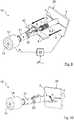
Die Erfindung betrifft somit auch ein Positionierungsverfahren für die Konfektionierung eines elektrischen Kabels, wonach ein vorderes, freies Ende eines auf einem Innenleiter des Kabels befestigten Innenleiterteils durch eine Zustellbewegung in einem auf dem Kabel zu montierenden Außenleiterteil in einer axialen Sollposition entlang einer Längsachse des Außenleiterteils positioniert wird.The invention thus also relates to a positioning method for the assembly of an electrical cable, according to which a front, free end of an inner conductor part fastened to an inner conductor of the cable is positioned in an axial desired position along a longitudinal axis of the outer conductor part by a feed movement in an outer conductor part to be mounted on the cable .
Hinsichtlich der Zustellbewegung kommt es lediglich auf eine relative Bewegung des Innenleiterteils zu dem Außenleiterteil an. Das Innenleiterteil kann durch eine Zustellbewegung des elektrischen Kabels entlang einer Vorschubrichtung in dem Außenleiterteil positioniert werden und/oder das Außenleiterteil kann durch die Zustellbewegung über das Innenleiterteil des elektrischen Kabels geschoben werden. Vorzugsweise wird eine Zustellbewegung des Kabels durchgeführt, während das Außenleiterteil feststeht.With regard to the infeed movement, all that matters is a relative movement of the inner conductor part to the outer conductor part. The inner conductor part can be positioned in the outer conductor part by a feed movement of the electrical cable along a feed direction and / or the outer conductor part can be pushed over the inner conductor part of the electrical cable by the feed movement. A feed movement of the cable is preferably carried out while the outer conductor part is stationary.
Insofern im Rahmen der Beschreibung oder der Patentansprüche auf die Angabe „vorne“ (zum Beispiel „vorderes Ende“) Bezug genommen wird, so ist diese Richtungsangabe auf das „steckerseitige Ende“ bzw. das „freie Ende“ des vorkonfektionierten elektrischen Kabels bezogen, das bei einer später geschlossenen Steckverbindung einem Gegensteckverbinder zugewandt ist. In den nachfolgenden Figuren bezieht sich die Richtungsangabe „vorne“ also jeweils auf das linke Ende des vorkonfektionierten Kabels. Die Richtungsangabe „hinten“ (zum Beispiel „hinteres Ende“) bezieht sich dementsprechend auf die dem steckerseitigen bzw. freien Ende abgewandte Kabelseite, d. h. auf das „kabelseitige Ende“ des vorkonfektionierten elektrischen Kabels; in den nachfolgenden Figuren also jeweils auf die rechte Seite des vorkonfektionierten Kabels.Insofar as reference is made to the “front” (for example “front end”) in the description or the claims, this directional information relates to the “plug end” or the “free end” of the pre-assembled electrical cable, the facing a mating connector in a later closed connector. In the following figures, the “front” direction refers to the left end of the pre-assembled cable. The directional indication "rear" (for example "rear end") accordingly refers to the cable side facing away from the plug-side or free end, ie. H. on the "cable end" of the pre-assembled electrical cable; in the following figures on the right side of the pre-assembled cable.
Bei dem erfindungsgemäßen Innenleiterteil handelt es sich um das innere Kontaktelement des auf dem elektrischen Kabel zu montierenden Steckverbinders. Grundsätzlich kann im Rahmen der Erfindung auch vorgesehen sein, dass das elektrische Kabel mit mehreren, z. B. parallel geführten Innenleiterteilen konfektioniert wird. Vorzugsweise betrifft die Erfindung allerdings die Konfektionierung eines Koaxialkabels, das lediglich einen einzigen Innenleiter aufweist, der elektrisch isoliert innerhalb eines Außenleiters, beispielsweise innerhalb eines Außenleiterschirms, geführt wird.The inner conductor part according to the invention is the inner contact element of the connector to be mounted on the electrical cable. Basically, it can also be provided in the context of the invention that the electrical cable with several, for. B. is assembled parallel inner conductor parts. However, the invention preferably relates to the assembly of a coaxial cable which has only a single inner conductor which is guided in an electrically insulated manner within an outer conductor, for example within an outer conductor shield.
Bei dem erfindungsgemäßen Außenleiterteil handelt es sich um das äußere Kontaktelement des auf dem elektrischen Kabel zu montierenden Steckverbinders, in der Regel um eine Außenleiter-Crimphülse. Das Außenleiterteil kann auch als Außenleiter-Kontaktelement oder als Steckerkörper bezeichnet werden. Das Außenleiterteil wird in der Regel derart montiert, dass es das Innenleiterteil vollständig in sich aufnimmt und beispielsweise elektromagnetisch abschirmt.The outer conductor part according to the invention is the outer contact element of the connector to be mounted on the electrical cable, generally an outer conductor crimp sleeve. The outer conductor part can also be referred to as an outer conductor contact element or as a plug body. The outer conductor part is generally mounted in such a way that it completely absorbs the inner conductor part and, for example, shields it electromagnetically.
In der Praxis kann zur Stabilisierung und Sicherstellung einer elektrischen Isolation zwischen dem wenigstens einen Innenleiterteil und dem Außenleiterteil ein Isolationskörper zwischen dem Außenleiterteil und dem Innenleiterteil vorgesehen sein, der sich zumindest Abschnittsweise über axial zwischen dem Innenleiterteil und dem Außenleiterteil erstreckt.In practice, to stabilize and ensure electrical insulation between the at least one inner conductor part and the outer conductor part, an insulation body can be provided between the outer conductor part and the inner conductor part, which extends at least in sections axially between the inner conductor part and the outer conductor part.
Zur Sicherstellung geeigneter elektrischer und/oder mechanischer Eigenschaften ist eine axiale Sollposition des Innenleiterteils zur Befestigung in dem Außenleiterteil vorgesehen. To ensure suitable electrical and / or mechanical properties, an axial nominal position of the inner conductor part is provided for fastening in the outer conductor part.
Erfindungsgemäß sieht das vorgeschlagene Positionierungsverfahren vor, dass die Sollposition unter Berücksichtigung eines Anschlussabstands des vorderen Endes des Innenleiterteils von einem dem Innenleiterteil zugewandten vorderen Ende einer auf dem Kabel befestigten Stützhülse berechnet wird. Während der Zustellbewegung wird eine axiale Istposition des vorderen Endes des Innenleiterteils relativ zu dem Außenleiterteil gemessen.According to the invention, the proposed positioning method provides that the target position is calculated taking into account a connection distance of the front end of the inner conductor part from a front end of the support sleeve facing the inner conductor part and fastened to the cable. During the infeed movement, an axial actual position of the front end of the inner conductor part is measured relative to the outer conductor part.
Bei dem Anschlussabstand handelt es sich in der Regel um ein besonders relevantes und auch toleranzbehaftetes Maß bei der Konfektionierung eines elektrischen Kabels. Dessen Berücksichtigung zur Bestimmung der Sollposition des vorderen Endes des Innenleiterteils in dem Außenleiterteil ermöglicht erfindungsgemäß die Herstellung konfektionierter bzw. mit einem Steckverbinder versehener elektrischer Kabel mit höchster Qualität und unter Vermeidung schwankender elektrischer und/oder mechanischer Eigenschaften.The connection distance is usually a particularly relevant and tolerant measure when assembling an electrical cable. Taking this into account in order to determine the desired position of the front end of the inner conductor part in the outer conductor part enables, according to the invention, the manufacture of prefabricated electrical cables or those provided with a plug connector with the highest quality and while avoiding fluctuating electrical and / or mechanical properties.
Der Anschlussabstand kann beispielsweise aufgrund einer vorhergehenden, hochgenauen Vorkonfektionierung des elektrischen Kabels sichergestellt sein. Der Anschlussabstand kann allerdings vorzugsweise auch auf Grundlage des im Rahmen des erfindungsgemäßen Gesamtkonzepts vorgeschlagenen Messkonzepts, beispielsweise mittels des vorstehend und nachfolgend beschriebenen Messverfahrens ermittelt werden. Der Anschlussabstand kann aber auch auf andere Art und Weise ermittelt werden oder bekannt sein. Das vorgeschlagene Positionierungsverfahren kann somit grundsätzlich auch unabhängig von dem beschriebenen Messkonzept verwendbar sein.The connection distance can be ensured, for example, on the basis of a previous, highly precise pre-assembly of the electrical cable. However, the connection distance can preferably also be determined on the basis of the measurement concept proposed as part of the overall concept according to the invention, for example by means of the measurement method described above and below. The connection distance can, however, also be determined in another way or be known. The proposed positioning method can therefore in principle also be used independently of the measurement concept described.
In einer Weiterbildung der Erfindung kann vorgesehen sein, dass die Sollposition auf Grundlage einer axialen Idealposition der Stützhülse in dem Außenleiterteil für ein anschließendes Befestigen des Außenleiterteils auf der Stützhülse berechnet wird.In a further development of the invention it can be provided that the target position is calculated on the basis of an axial ideal position of the support sleeve in the outer conductor part for a subsequent fastening of the outer conductor part on the support sleeve.
Zur Sicherstellung vorteilhafter mechanischer und/oder elektrischer Eigenschaften eines konfektionierten bzw. mit einem Steckverbinder versehenen elektrischen Kabels ist insbesondere die korrekte Positionierung der Stützhülse in dem Außenleiterteil ein wichtiges Kriterium. Vorzugsweise befindet sich die Stützhülse während der Befestigung, insbesondere während dem Vercrimpen des Außenleiterteils, in der vorgesehenen Idealposition innerhalb des Außenleiterteils. Da sich ausgehend von dem vorderen, dem Innenleiterteil zugewandten Ende der Stützhülse der Anschlussabstand bis zum vorderen, freien Ende des Innenleiterteils erstreckt, kann bei bekanntem oder zumindest ausreichend genau bekanntem Anschlussabstand ausgehend von dem vorderen Ende des Innenleiterteils auf die Idealposition der Stützhülse in dem Außenleiterteil geschlossen werden. Aus diesem Grunde kann auf vorteilhafte Weise im Rahmen der Erfindung die Sollposition des vorderen Endes des Innenleiterteils derart bestimmt werden, dass sich unter Berücksichtigung des Anschlussabstands die Stützhülse genau dann in der Idealposition befindet, wenn sich das vordere, freie Ende des Innenleiterteils in der berechneten Sollposition befindet.In order to ensure advantageous mechanical and / or electrical properties of an assembled or provided with an electrical cable connector, the correct positioning of the support sleeve in the outer conductor part is an important criterion. The support sleeve is preferably in the intended ideal position within the outer conductor part during fastening, in particular during crimping of the outer conductor part. Since, starting from the front end of the support sleeve facing the inner conductor part, the connection distance extends to the front, free end of the inner conductor part, the ideal position of the support sleeve in the outer conductor part can be inferred from the front end of the inner conductor part if the connection distance is known or at least sufficiently well known will. For this reason, the target position of the front end of the inner conductor part can advantageously be determined within the scope of the invention such that, taking into account the connection distance, the support sleeve is in the ideal position exactly when the front, free end of the inner conductor part is in the calculated target position located.
Auf ähnliche Art und Weise können im Rahmen der Erfindung auch Idealpositionen anderer Abschnitte des vorkonfektionierten elektrischen Kabels innerhalb des Außenleiterteils für die Berechnung der Sollposition herangezogen werden.In a similar manner, ideal positions of other sections of the pre-assembled electrical cable within the outer conductor part can also be used for the calculation of the desired position within the scope of the invention.
Eine Positionierung des Innenleiterteils in dem Außenleiterteil kann unter Berücksichtigung der Istposition des vorderen Endes des Innenleiterteils besonders genau und einfach erfolgen, da es sich bei dem Innenleiterteil um das vordere, abschließende Ende des vorkonfektionierten elektrischen Kabels handelt, dessen Position somit technisch einfach ermittelbar ist. Eine aufwändige direkte Ermittlung, beispielsweise der Idealposition der Stützhülse in dem Außenleiterteil, kann somit vermieden werden.Positioning of the inner conductor part in the outer conductor part can take place particularly precisely and simply, taking into account the actual position of the front end of the inner conductor part, since the inner conductor part is the front, final end of the pre-assembled electrical cable, the position of which is thus technically easy to determine. A complex direct determination, for example the ideal position of the support sleeve in the outer conductor part, can thus be avoided.
In einer Weiterbildung der Erfindung kann vorgesehen sein, dass die axiale Idealposition der Stützhülse in dem Außenleiterteil entsprechend der Position des vorderen Endes der Stützhülse an einer innenliegenden Schulter des Außenleiterteils bestimmt wird.In a further development of the invention it can be provided that the ideal axial position of the support sleeve in the outer conductor part is determined according to the position of the front end of the support sleeve on an inner shoulder of the outer conductor part.
Die ideale Ausrichtung der Stützhülse an der innenliegenden Schulter des Außenleiterteils, insbesondere zur Minimierung eines Luftspalts zwischen der Schulter und der Stützhülse bei einem befestigten bzw. vercrimpten Außenleiterteil, kann die elektrischen Eigenschaften des konfektionierten elektrischen Kabels verbessern. Aufgrund der Vermeidung eines Luftspalts können Unstetigkeiten im Impedanzverlauf minimiert werden. Auch eine gezielte Impedanzanpassung beim Übergang zwischen dem elektrischen Kabel und einem Steckverbinder kann sich durch Beeinflussung des Luftspalts realisieren lassen.The ideal alignment of the support sleeve on the inner shoulder of the outer conductor part, in particular to minimize an air gap between the shoulder and the support sleeve in the case of a fastened or crimped outer conductor part, can improve the electrical properties of the assembled electrical cable. By avoiding an air gap, discontinuities in the impedance curve can be minimized. Targeted impedance matching at the transition between the electrical cable and a connector can also be achieved by influencing the air gap.
Grundsätzlich kann aber auch eine sonstige Idealposition der Stützhülse in dem Außenleiterteil angestrebt werden.In principle, however, another ideal position of the support sleeve in the outer conductor part can also be sought.
In einer Weiterbildung der Erfindung kann vorgesehen sein, dass das Kabel in eine Greifeinrichtung eingespannt wird, wonach die Greifeinrichtung linear entlang der Längsachse des Außenleiterteils verschoben wird und/oder wonach das Außenleiterteil linear entlang der Längsachse des Außenleiterteils verschoben wird, um das Innenleiterteil in dem Außenleiterteil zu positionieren.In a further development of the invention it can be provided that the cable is clamped in a gripping device, after which the gripping device is linear along the longitudinal axis of the outer conductor part is displaced and / or after which the outer conductor part is displaced linearly along the longitudinal axis of the outer conductor part in order to position the inner conductor part in the outer conductor part.
Die Greifeinrichtung kann insbesondere eine oder mehrere Pressbacken aufweisen. Die Greifeinrichtung greift das Kabel vorzugsweise an dessen Kabelmantel.The gripping device can in particular have one or more pressing jaws. The gripping device preferably grips the cable on its cable jacket.
Wie bereits erwähnt, kann allerdings auch vorgesehen sein, dass lediglich oder auch zusätzlich das Außenleiterteil verschoben wird, um das Innenleiterteil in sich zu positionieren. Es kann auch in diesem Fall eine Greifeinrichtung vorgesehen sein, die das Kabel einspannt, dann allerdings im Wesentlichen an derselben axialen Position fixiert.As already mentioned, however, it can also be provided that the outer conductor part is only or additionally displaced in order to position the inner conductor part in itself. In this case too, a gripping device can be provided which clamps the cable, but then fixes it essentially at the same axial position.
In einer Weiterbildung der Erfindung kann außerdem vorgesehen sein, dass die axiale Istposition des vorderen Endes des Innenleiterteils relativ zu dem Außenleiterteil mittels einer Sensoreinrichtung gemessen wird.In a further development of the invention it can also be provided that the actual axial position of the front end of the inner conductor part relative to the outer conductor part is measured by means of a sensor device.
In einer Weiterbildung kann als Sensoreinrichtung insbesondere ein Messtaster, ein induktiver Sensor, ein kapazitiver Sensor und/oder ein optischer Sensor verwendet werden.In a further development, a measuring probe, an inductive sensor, a capacitive sensor and / or an optical sensor can in particular be used as the sensor device.
Vorzugsweise wird ein Messtaster verwendet, der durch direkten mechanischen Kontakt mit dem vorderen, freien Ende des Innenleiterteils dessen axialen Abstand von dem Referenzanschlag erfasst. Ein Messtaster kann sich aufgrund der hohen Genauigkeit der mechanischen, direkten Messung des axialen Abstands besonders gut eignen.A probe is preferably used which, by direct mechanical contact with the front, free end of the inner conductor part, detects its axial distance from the reference stop. A probe can be particularly suitable due to the high accuracy of the mechanical, direct measurement of the axial distance.
Allerdings kann auch eine berührungslose Erfassung der Position des vorderen Endes des Innenleiterteils relativ zu dem Referenzanschlag von Vorteil sein, beispielsweise mittels eines induktiven Sensors oder eines kapazitiven Sensors. Es kann auch ein optischer Sensor zur Erfassung des axialen Abstands vorgesehen sein, beispielsweise die Erfassung der Position des vorderen, freien Endes des Innenleiterteils mittels einer Kamera.However, contactless detection of the position of the front end of the inner conductor part relative to the reference stop can also be advantageous, for example by means of an inductive sensor or a capacitive sensor. An optical sensor can also be provided for detecting the axial distance, for example detecting the position of the front, free end of the inner conductor part using a camera.
In einer vorteilhaften Weiterbildung der Erfindung kann vorgesehen sein, dass die Sensoreinrichtung definiert zu dem Außenleiterteil positioniert und fixiert wird.In an advantageous development of the invention, it can be provided that the sensor device is positioned and fixed in relation to the outer conductor part.
Beispielsweise kann die Sensoreinrichtung an einem vorderen Ende des Außenleiterteils angeschlagen und kraft- und/oder formschlüssig fixiert werden. Die Sensoreinrichtung kann zur Unterstützung der Fixierung über einen vorderen Abschnitt des Außenleiterteils geschoben werden oder in einen vorderen Abschnitt des Außenleiterteils zumindest teilweise eindringen. Die Sensoreinrichtung kann mit dem Außenleiterteil ggf. verrasten, beispielsweise unter Verwendung von in dem Außenleiterteil für dessen Montage in einem Steckverbindergehäuse ohnehin vorhandener Rastmittel, Aufnahmen für Rastmittel oder Absätzen.For example, the sensor device can be attached to a front end of the outer conductor part and fixed in a force-locking and / or form-fitting manner. To support the fixation, the sensor device can be pushed over a front section of the outer conductor part or at least partially penetrate into a front section of the outer conductor part. The sensor device can possibly latch with the outer conductor part, for example using latching means, receptacles for latching means or shoulders, which are present in the outer conductor part for its assembly in a plug connector housing.
Grundsätzlich muss die Sensoreinrichtung allerdings nicht an dem Außenleiterteil fixiert werden. Insbesondere kann die Sensoreinrichtung auch an einer bekannten Position relativ zu dem Außenleiterteil angeordnet sein.In principle, however, the sensor device does not have to be fixed to the outer conductor part. In particular, the sensor device can also be arranged at a known position relative to the outer conductor part.
In einer Weiterbildung kann vorgesehen sein, dass unter Berücksichtigung der Idealposition eines Referenzkabels in dem Außenleiterteil eine Sollposition für das Referenzkabel bestimmt wird, wobei die Sensoreinrichtung auf Grundlage der Sollposition des Referenzkabels definiert positioniert und fixiert wird, um die Istposition des zu konfektionierenden Kabels zumindest in einem vorderen Abschnitt des Außenleiterteils zu messen.In a further development it can be provided that, taking into account the ideal position of a reference cable in the outer conductor part, a target position for the reference cable is determined, the sensor device being positioned and fixed in a defined manner on the basis of the target position of the reference cable in order to at least in one position the actual position of the cable to be assembled to measure the front section of the outer conductor part.
Dabei ist die Sensoreinrichtung vorzugsweise an dem Außenleiterteil fixiert; dies ist jedoch nicht unbedingt erforderlich. Eine Fixierung der Sensoreinrichtung an einer bekannten Position relativ zu dem Außenleiterteil kann ebenfalls ausreichend sein.The sensor device is preferably fixed to the outer conductor part; however, this is not absolutely necessary. Fixing the sensor device at a known position relative to the outer conductor part can also be sufficient.
Bei dem vorderen Abschnitt des Außenleiterteils kann es sich beispielsweise um die vordere Hälfte des Außenleiterteils, das vordere Drittel des Außenleiterteils, das vordere Viertel des Außenleiterteils, das vordere Achtel des Außenleiterteils, das vordere Sechzehntel des Außenleiterteils oder einen noch kürzeren vorderen Abschnitt des Außenleiterteils handeln - jeweils bezogen auf die axiale Gesamtlänge des Außenleiterteils.The front section of the outer conductor part can be, for example, the front half of the outer conductor part, the front third of the outer conductor part, the front quarter of the outer conductor part, the front eighth of the outer conductor part, the front sixteenth of the outer conductor part or an even shorter front section of the outer conductor part - each based on the total axial length of the outer conductor part.
Eine Positionierung der Sensoreinrichtung kann durch Berücksichtigung der Idealposition des Referenzkabels dahingehend erfolgen, dass die Sensoreinrichtung toleranzbedingte Abweichungen der Position des vorderen, freien Endes des Innenleiterteils für die einzelnen, zu konfektionierenden Kabel bei der Positionierung noch zu erfassen vermag. Eine Kalibrierung der Sensoreinrichtung kann dahingehend erfolgen, dass die Position des vorderen, freien Endes des Innenleiterteils des Referenzkabels in dem Außenleiterteil als Nullmaß bzw. Referenz/Nullposition definiert wird.The sensor device can be positioned by taking into account the ideal position of the reference cable such that the sensor device can still detect tolerance-related deviations in the position of the front, free end of the inner conductor part for the individual cables to be assembled during the positioning. The sensor device can be calibrated in such a way that the position of the front, free end of the inner conductor part of the reference cable in the outer conductor part is defined as a zero dimension or reference / zero position.
Beispielsweise kann eine als Messtaster ausgebildete Sensoreinrichtung derart zu dem vorderen Ende des Innenleiterteils des Referenzkabels positioniert werden, dass sich eine bewegliche Messspitze des Messtasters bei der Vermessung des Referenzkabels in einer Mittelstellung befindet, in der die Messspitze ausreichend positiven und negativen Hub zur Verfügung hat, um toleranzbedingt zu erwartende Abweichungen des Anschlussabstands der einzelnen, zu konfektionierenden elektrischen Kabel erfassen zu können.For example, a sensor device designed as a measuring probe can be positioned at the front end of the inner conductor part of the reference cable in such a way that a movable measuring tip of the measuring probe is in a central position during the measurement of the reference cable, in which the measuring tip has sufficient positive and negative travel available to Deviations in the connection distance of the to be able to record individual electrical cables to be assembled.
In einer Weiterbildung der Erfindung kann vorgesehen sein, dass die Istposition während der Zustellung zeitkontinuierlich oder zeitdiskret (in einem Zeitraster) zumindest in einem vorderen Abschnitt des Außenleiterteils gemessen wird.In a further development of the invention it can be provided that the actual position is measured continuously during the infeed or discrete-time (in a time grid) at least in a front section of the outer conductor part.
Somit kann das Messen der Istposition während der gesamten Zustellbewegung des Innenleiterteils in das Außenleiterteil oder vorzugsweise nur in einem vorderen Abschnitt des Außenleiterteils und somit auch nur kurz vor Erreichen der Sollposition des Innenleiterteils in dem Außenleiterteil erfolgen.The actual position can thus be measured during the entire infeed movement of the inner conductor part into the outer conductor part or preferably only in a front section of the outer conductor part and thus only shortly before the desired position of the inner conductor part is reached in the outer conductor part.
Neben der zeitkontinuierlichen oder zeitdiskreten Messung kann auch vorgesehen sein, dass nur eine Einzelmessung erfolgt, wonach erst das tatsächliche Erreichen der Sollposition oder das Überfahren einer Messposition kurz vor der Sollposition detektiert wird. Beispielsweise kann vorgesehen sein, dass das Erreichen der Sollposition durch Anschlagen des vorderen Endes des Innenleiterteils an einer Messspitze eines Messtasters erfasst wird.In addition to the continuous-time or discrete-time measurement, provision can also be made for only a single measurement to be carried out, after which the actual reaching of the target position or passing over a measuring position shortly before the target position is detected. For example, provision can be made for reaching the desired position by striking the front end of the inner conductor part on a measuring tip of a probe.
In einer Weiterbildung der Erfindung kann vorgesehen sein, dass das Innenleiterteil in dem Außenleiterteil unter Berücksichtigung der gemessenen Istposition im Rahmen einer Positionsregelung positioniert wird.In a further development of the invention it can be provided that the inner conductor part is positioned in the outer conductor part taking into account the measured actual position within the scope of a position control.
Die zeitkontinuierlich oder zeitdiskret gemessenen Istpositionen können somit einer mit der Zustellbewegung betrauten Transporteinrichtung für eine Regelung der Zustellbewegung zur Verfügung gestellt werden.The actual positions measured continuously or discretely in time can thus be made available to a transport device entrusted with the infeed movement for regulating the infeed movement.
Im Rahmen einer automatischen Positionsregelung kann somit kontinuierlich oder in einem bestimmten Zeitraster eine gemessene Abweichung der Istposition von der Sollposition von der Sensoreinrichtung, gegebenenfalls unter Zwischenschaltung einer Überwachungseinheit, der Transporteinrichtung gemeldet werden.As part of an automatic position control, a measured deviation of the actual position from the target position can thus be reported continuously or in a certain time grid by the sensor device, optionally with the interposition of a monitoring unit, to the transport device.
Die Erfindung betrifft auch eine Positionierungsanordnung für die Konfektionierung eines elektrischen Kabels, aufweisend eine Transporteinrichtung, die ausgebildet ist, um ein vorderes, freies Ende eines auf einem Innenleiter des Kabels befestigten Innenleiterteils durch eine Zustellbewegung in einem auf dem Kabel zu montierenden Außenleiterteil in einer axialen Sollposition entlang einer Längsachse des Außenleiterteils zu positionieren.The invention also relates to a positioning arrangement for the assembly of an electrical cable, comprising a transport device which is designed to move a front, free end of an inner conductor part fastened to an inner conductor of the cable by a feed movement in an outer conductor part to be mounted on the cable in an axial desired position to position along a longitudinal axis of the outer conductor part.
Die Transporteinrichtung kann ausgebildet sein, um das Innenleiterteil mittels der Bewegung des elektrischen Kabels in das Außenleiterteil zuzustellen und/oder um das Außenleiterteil über das Innenleiterteil zu bewegen. Im Rahmen der Erfindung kommt es lediglich auf eine relative Bewegung des Innenleiterteils zu dem Außenleiterteil an. Vorzugsweise ist die Transporteinrichtung ausgebildet und eingerichtet, um das elektrische Kabel entlang einer Vorschubrichtung axial zuzustellen, um das Innenleiterteil in das Außenleiterteil einzuschieben, während das Außenleiterteil stillsteht.The transport device can be designed to feed the inner conductor part into the outer conductor part by means of the movement of the electrical cable and / or to move the outer conductor part over the inner conductor part. In the context of the invention, it is only a matter of a relative movement of the inner conductor part to the outer conductor part. The transport device is preferably designed and set up to axially advance the electrical cable along a feed direction in order to push the inner conductor part into the outer conductor part while the outer conductor part is stationary.
Erfindungsgemäß weist die Positionierungsanordnung eine Sensoreinrichtung auf, die eingerichtet ist, um während der Zustellung eine axiale Istposition des vorderen Endes des Innenleiterteils relativ zu dem Außenleiterteil zu messen. Ferner weist die Positionierungseinrichtung eine Steuer- und/oder Regeleinrichtung auf die eingerichtet ist, um die Sollposition unter Berücksichtigung der Messung der Istposition des vorderen Endes des Innenleiterteils und unter Berücksichtigung eines Anschlussabstands des vorderen Endes des Innenleiterteils von einem dem Innenleiterteil zugewandten, vorderen Ende einer auf dem Kabel befestigten Stützhülse zu berechnen und mittels der Transporteinrichtung in der Sollposition zu positionieren.According to the invention, the positioning arrangement has a sensor device which is set up to measure an axial actual position of the front end of the inner conductor part relative to the outer conductor part during the infeed. Furthermore, the positioning device has a control and / or regulating device which is set up to adjust the target position, taking into account the measurement of the actual position of the front end of the inner conductor part and taking into account a connection distance of the front end of the inner conductor part from a front end facing the inner conductor part to calculate the support sleeve attached to the cable and to position it in the desired position using the transport device.
Im Rahmen der Konfektionierung elektrischer Kabel können während der Montage eines Steckverbinders auf das elektrische Kabel verschiedene Längenmaße und Abstandsmaße zur Einhaltung von Toleranzen und zur Gewährleistung ausreichend guter mechanischer und/oder elektrischer Eigenschaften des an dem Kabel befestigten Steckverbinders vorgesehen sein. Die Erfindungsgemäße Positionierungsanordnung vermag die Einhaltung genannter Vorgaben sicherzustellen.As part of the assembly of electrical cables, various lengths and spacing dimensions can be provided during the assembly of a plug connector on the electrical cable to comply with tolerances and to ensure sufficiently good mechanical and / or electrical properties of the plug connector attached to the cable. The positioning arrangement according to the invention is able to ensure compliance with the specified requirements.
Erfindungsgemäß kann eine vorteilhafte Prozessregelung bereitgestellt und Verarbeitungstoleranzen durch die Prozessüberwachung ausgeglichen werden.According to the invention, an advantageous process control can be provided and processing tolerances can be compensated for by the process monitoring.
In einer Weiterbildung der Erfindung kann vorgesehen sein, dass die Sensoreinrichtung einen Messtaster, einen induktiven Sensor, einen kapazitiven Sensor und/oder einen optischen Sensor aufweist.In a further development of the invention it can be provided that the sensor device has a measuring probe, an inductive sensor, a capacitive sensor and / or an optical sensor.
Die Sensoreinrichtung kann auch auf Grundlage sonstiger Technologien ausgebildet sein. Vorzugsweise ist die Sensoreinrichtung als Messtaster ausgebildet, um die Position des vorderen Endes des Innenleiterteils durch direkte, mechanische Kontaktierung hochgenau zu erfassen.The sensor device can also be designed on the basis of other technologies. The sensor device is preferably designed as a probe in order to detect the position of the front end of the inner conductor part with high precision by direct mechanical contacting.
In einer Weiterbildung der Erfindung ist die Sensoreinrichtung vorzugsweise definiert zu dem Außenleiterteil positioniert und fixiert angeordnet.In a development of the invention, the sensor device is preferably positioned in a defined manner with respect to the outer conductor part and arranged in a fixed manner.
Die Sensoreinrichtung kann auch mittels einer Aktuatoreinrichtung kraftschlüssig an dem Außenleiterteil fixiert bzw. an das Außenleiterteil gepresst werden.The sensor device can also be non-positively connected to the actuator device Outer conductor part are fixed or pressed against the outer conductor part.
Insbesondere kann es von Vorteil sein, die Sensoreinrichtung definiert zu dem Außenleiterteil zu positionieren und gegebenenfalls zu fixieren, da dann die Beziehung bzw. der Abstand zwischen der Sensoreinrichtung und dem Außenleiterteil bekannt ist und somit die axiale Istposition sowie die Sollposition des vorderen, freien Endes des Innenleiterteils relativ zu dem vorderen Ende des Außenleiterteils einfach abgeleitet werden kann.In particular, it can be advantageous to position the sensor device in a defined manner with respect to the outer conductor part and, if necessary, to fix it, since then the relationship or the distance between the sensor device and the outer conductor part is known, and thus the axial actual position and the desired position of the front, free end of the Inner conductor part can be easily derived relative to the front end of the outer conductor part.
Die Erfindung betrifft außerdem ein Computerprogrammprodukt mit Programmcodemitteln, um das vorstehend und nachfolgend beschriebene Positionierungsverfahren durchzuführen, wenn das Programm auf einer Regel- und/oder Steuereinrichtung einer Positionierungsanordnung gemäß den vorstehenden und nachfolgenden Ausführungen ausgeführt wird.The invention also relates to a computer program product with program code means in order to carry out the positioning method described above and below when the program is executed on a regulating and / or control device of a positioning arrangement according to the above and following explanations.
Die Regel- und/oder Steuereinrichtung kann vorzugsweise als speicherprogrammierbare Steuerung (SPS) ausgebildet sein. Anstelle einer SPS kann allerdings auch eine beliebige weitere Einrichtung zur Implementierung der Regel- und/oder Steuereinrichtung vorgesehen sein, beispielsweise ein beliebiger Mikroprozessor, eine oder mehrere Anordnungen diskreter elektrischer Bauteile auf einer Leiterplatte, eine anwendungsspezifische integrierte Schaltung (ASIC) oder eine sonstige programmierbare Schaltung, beispielsweise auch ein Field Programmable Gate Array (FPGA), eine programmierbare logische Anordnung (PLA) und/oder ein handelsüblicher Computer.The regulating and / or control device can preferably be designed as a programmable logic controller (PLC). Instead of a PLC, however, any other device for implementing the regulating and / or control device can also be provided, for example any microprocessor, one or more arrangements of discrete electrical components on a printed circuit board, an application-specific integrated circuit (ASIC) or another programmable circuit , for example also a field programmable gate array (FPGA), a programmable logic arrangement (PLA) and / or a commercially available computer.
Schließlich betrifft das einheitliche erfindungsgemäße Gesamtkonzept zur Lösung der Aufgabe auch ein Konfektionierungsverfahren für die Konfektionierung eines elektrischen Kabels, wobei ein Messverfahren gemäß den vorstehenden und nachfolgenden Ausführungen durchgeführt wird, wonach ein Positionierungsverfahren gemäß den vorstehenden und nachfolgenden Ausführungen durchgeführt wird, und wonach die Stützhülse in dem Außenleiterteil befestigt wird.Finally, the uniform overall concept according to the invention for solving the task also relates to a manufacturing method for the assembly of an electrical cable, a measuring method being carried out in accordance with the above and following explanations, after which a positioning method is carried out in accordance with the preceding and subsequent explanations, and after which the support sleeve in Outer conductor part is attached.
Grundidee des erfindungsgemäßen Konfektionierungsverfahrens ist es, ein für die Konfektionierung kritisches Maß, insbesondere einen Anschlussabstand zwischen einem vorderen, freien Ende des Innenleiterteils und einem dem Innenleiterteil zugewandten, vorderen Ende der Stützhülse mittels eines Messverfahrens zu ermitteln und anschließend im Rahmen eines Positionierungsverfahrens des Kabels zur Positionierung des Innenleiterteils des Kabels in einem Außenleiterteil des späteren Steckverbinders zu berücksichtigen.The basic idea of the assembly method according to the invention is to determine a dimension that is critical for the assembly, in particular a connection distance between a front, free end of the inner conductor part and a front end of the support sleeve facing the inner conductor part by means of a measurement method and then as part of a positioning method of the cable for positioning of the inner conductor part of the cable in an outer conductor part of the future connector.
Auf diese Weise kann das Außenleiterteil des Steckverbinders optimal zu dem Innenleiterteil und/oder zu einer auf dem Kabel befestigten Stützhülse axial positioniert werden.In this way, the outer conductor part of the connector can be optimally positioned axially to the inner conductor part and / or to a support sleeve fastened to the cable.
Das erfindungsgemäße Messkonzept und dass erfindungsgemäße Positionierungskonzept können allerdings auch unabhängig voneinander umgesetzt werden.However, the measurement concept according to the invention and the positioning concept according to the invention can also be implemented independently of one another.
Eine ungenaue Positionierung eines Innenleiterteils bzw. eines vorkonfektionierten elektrischen Kabels innerhalb eines Außenleiterteils oder insgesamt innerhalb eines Steckverbinders und gegebenenfalls eine schwankende Qualität, insbesondere schwankende HF-Leistung, von Steckverbindern kann erfindungsgemäß vermieden werden.An inaccurate positioning of an inner conductor part or a prefabricated electrical cable within an outer conductor part or overall within a plug connector and possibly a fluctuating quality, in particular fluctuating RF power, of plug connectors can be avoided according to the invention.
Grundsätzlich kann das vorgeschlagene Konfektionierungsverfahren auch noch weitere Verfahrensschritte aufweisen. Insbesondere kann vorgesehen sein, dass vor Durchführung des Messverfahrens das elektrische Kabel bereits vorkonfektioniert wird.In principle, the proposed assembly process can also have further process steps. In particular, it can be provided that the electrical cable is already pre-assembled before the measurement method is carried out.
Im Rahmen einer Vorkonfektionierung kann insbesondere vorgesehen sein, einen Kabelmantel des Kabels an einem vorderen Abschnitt des Kabels abzuisolieren und zumindest teilweise von dem Kabel abzuziehen. Anschließend kann die Stützhülse auf den freigelegten Außenleiter, insbesondere ein Kabelschirmgeflecht und/oder auf den Kabelmantel aufgeschoben und befestigt, insbesondere vercrimpt, werden. Wiederum anschließend kann der Außenleiter des Kabels, insbesondere ein Kabelschirmgeflecht, über die Stützhülse nach hinten zurückgeschlagen oder ausgehend von der Stützhülse abgetrennt werden. Anschließend kann eine gegebenenfalls vorhandene Kabelfolie zumindest abschnittsweise abgetrennt werden. Wiederum anschließend kann ein zwischen dem Außenleiter des Kabels und dem wenigstens einen Innenleiter des Kabels angeordnetes Dielektrikum abisoliert und somit der wenigstens eine Innenleiter des Kabels freigelegt werden. Schließlich kann ein Innenleiterteil auf jeden vorhandenen Innenleiter des Kabels befestigt, insbesondere aufgecrimpt, werden.In the course of pre-assembly, provision can in particular be made to strip a cable sheath of the cable from a front section of the cable and at least partially pull it off the cable. The support sleeve can then be pushed onto the exposed outer conductor, in particular a cable shield braid and / or onto the cable sheath and fastened, in particular crimped. Then again, the outer conductor of the cable, in particular a cable shield braid, can be pushed back over the support sleeve or separated from the support sleeve. Any cable foil that may be present can then be separated off at least in sections. Then again, a dielectric arranged between the outer conductor of the cable and the at least one inner conductor of the cable can be stripped and the at least one inner conductor of the cable can thus be exposed. Finally, an inner conductor part can be attached, in particular crimped, onto any existing inner conductor of the cable.
Die Befestigung der Stützhülse in dem Außenleiterteil erfolgt vorzugsweise durch Vercrimpen des Außenleiterteils auf der Stützhülse und/oder auf dem Kabelmantel.The support sleeve is preferably fastened in the outer conductor part by crimping the outer conductor part on the support sleeve and / or on the cable jacket.
Im Rahmen des Konfektionierungsverfahrens kann nach der Befestigung des Außenleiterteils vorgesehen sein, das Außenleiterteil in einem Gehäuse eines Steckverbinders zu montieren, insbesondere in einem Kunststoffgehäuse zu verrasten und zu sichern. Zuvor oder anschließend kann außerdem vorgesehen sein, ein Isolierteil zwischen das Außenleiterteil und das wenigstens einen Innenleiterteil einzuschieben, um die elektrische Isolation und die Ausrichtung des wenigstens einen Innenleiterteils in dem Außenleiterteil sicherzustellen.Within the scope of the assembly process, after the outer conductor part has been fastened, provision can be made to mount the outer conductor part in a housing of a plug connector, in particular to latch and secure it in a plastic housing. Before or afterwards, an insulating part can also be provided between the Insert the outer conductor part and the at least one inner conductor part in order to ensure the electrical insulation and the alignment of the at least one inner conductor part in the outer conductor part.
Das einheitliche erfindungsgemäße Gesamtkonzept betrifft schließlich auch eine Konfektionierungsanordnung für die Konfektionierung eines elektrischen Kabels, aufweisend eine vorstehend und nachfolgend beschriebene Messanordnung sowie eine Positionierungsanordnung gemäß den vorstehenden und nachfolgenden Ausführungen.Finally, the uniform overall concept according to the invention also relates to an assembly arrangement for the assembly of an electrical cable, comprising a measurement arrangement described above and below and a positioning arrangement according to the above and following explanations.
Die Konfektionierungsanordnung kann optional außerdem noch weitere Vorrichtungsmerkmale aufweisen, beispielsweise Vorrichtungen für eine Vorkonfektionierung des Kabels, insbesondere zur Montage der Stützhülse und für die Abisolierung von Kabelbestandteilen.The assembly arrangement can optionally also have further device features, for example devices for pre-assembling the cable, in particular for assembling the support sleeve and for stripping cable components.
Eine erfindungsgemäße Konfektionsmaschine bzw. Konfektionierungsanordnung kann eine Konfektionierung elektrischer Kabel mit Steckverbindern insbesondere mit gleichbleibender, hoher Qualität bereitstellen.An assembly machine or assembly arrangement according to the invention can provide an assembly of electrical cables with plug connectors, in particular with a constant, high quality.
Die Erfindung, d. h. das beschriebene Messkonzept, das Positionierungskonzept, das Konfektionierungsverfahren und die Konfektionierungsanordnung ist nicht auf eine spezifische Steckverbinderart bzw. auf einen spezifischen Steckverbinder beschränkt, wobei sich die Erfindung insbesondere für die Konfektionierung elektrischer Kabel mit Steckverbindern für die Hochfrequenztechnik eignet. Ein entsprechender Steckverbinder kann somit vorzugsweise als Hochfrequenz-Steckverbinder, insbesondere als PL-Steckverbinder, BNC-Steckverbinder, TNC-Steckverbinder, SMBA (FAKRA)-Steckverbinder, N-Steckverbinder, 7-16-Steckverbinder, SMA-Steckverbinder, SMB-Steckverbinder, SMS-Steckverbinder, SMC-Steckverbinder, SMP-Steckverbinder, BMS-Steckverbinder, HFM-Steckverbinder, HSD-Steckverbinder, H-MTD-Steckverbinder, BMK-Steckverbinder, Mini-Coax-Steckverbinder oder Makax-Steckverbinder ausgebildet sein.The invention, i. H. the measurement concept described, the positioning concept, the assembly method and the assembly arrangement is not restricted to a specific connector type or to a specific connector, the invention being particularly suitable for the assembly of electrical cables with connectors for high-frequency technology. A corresponding connector can thus preferably be used as a high-frequency connector, in particular as a PL connector, BNC connector, TNC connector, SMBA (FAKRA) connector, N connector, 7-16 connector, SMA connector, SMB connector, SMS connectors, SMC connectors, SMP connectors, BMS connectors, HFM connectors, HSD connectors, H-MTD connectors, BMK connectors, mini-coax connectors or Makax connectors.
Der erfindungsgemäße Steckverbinder kann besonders vorteilhaft innerhalb eines Fahrzeugs, insbesondere eines Kraftfahrzeugs, verwendet werden. Mögliche Einsatzgebiete sind autonomes Fahren, Fahrer-Assistenzsysteme, Navigationssysteme, „Infotainment“-Systeme, Fond-Entertainment-Systeme, Internetverbindungen und Wireless Gigabit (IEEE 802.11ad Standard). Mögliche Anwendungen betreffen hochaufgelöste Kameras, beispielsweise 4K- und 8K-Kameras, Sensorik, Onboard-Computer, hochauflösende Bildschirme, hochauflösende Armaturenbretter, 3D-Navigationsgeräte und Mobilfunkgeräte.The connector according to the invention can be used particularly advantageously within a vehicle, in particular a motor vehicle. Possible areas of application are autonomous driving, driver assistance systems, navigation systems, "infotainment" systems, rear-seat entertainment systems, internet connections and wireless gigabit (IEEE 802.11ad standard). Possible applications concern high-resolution cameras, for example 4K and 8K cameras, sensors, onboard computers, high-resolution screens, high-resolution dashboards, 3D navigation devices and mobile devices.
Der erfindungsgemäße Steckverbinder bzw. das erfindungsgemäße elektrische Kabel eignet sich allerdings für beliebige Anwendungen innerhalb der gesamten Elektrotechnik und ist nicht auf den Einsatz in der Fahrzeugtechnik beschränkt zu verstehen.However, the connector according to the invention or the electrical cable according to the invention is suitable for any application within the entire electrical engineering and is not to be understood as being restricted to use in vehicle technology.
Merkmale, die im Zusammenhang mit dem Messverfahren, der Messanordnung, der Referenzeinrichtung, dem Positionierungsverfahren, der Positionierungsanordnung, dem Konfektionierungsverfahren, der Konfektionierungsanordnung und einem der Computerprogrammprodukte beschrieben wurden, sind jeweils untereinander austauschbar, sofern dies technisch nicht ausgeschlossen ist. Beispielsweise können Merkmale, die im Zusammenhang mit dem erfindungsgemäßen Messverfahren bzw. mit der erfindungsgemäßen Messanordnung beschrieben wurden, auch für das erfindungsgemäße Positionierungsverfahren bzw. für die Positionierungsanordnung vorteilhaft umsetzbar sein - und umgekehrt.Features that have been described in connection with the measuring method, the measuring arrangement, the reference device, the positioning method, the positioning arrangement, the packaging method, the packaging arrangement and one of the computer program products are interchangeable, unless this is not technically excluded. For example, features that have been described in connection with the measuring method according to the invention or with the measuring arrangement according to the invention can also advantageously be implemented for the positioning method according to the invention or for the positioning arrangement - and vice versa.
Ferner können Vorteile, die im Zusammenhang mit dem Messverfahren, der Messanordnung, der Referenzeinrichtung, dem Positionierungsverfahren, der Positionierungsanordnung, dem Konfektionierungsverfahren, der Konfektionierungsanordnung und einem der Computerprogrammprodukte beschrieben wurden, auch für die jeweils anderen Gegenstände vorteilhaft sein.Furthermore, advantages which have been described in connection with the measuring method, the measuring arrangement, the reference device, the positioning method, the positioning arrangement, the packaging method, the packaging arrangement and one of the computer program products can also be advantageous for the respective other objects.
Ergänzend sei darauf hingewiesen, dass Begriffe, wie „umfassend“, aufweisen oder „mit“, keine anderen Merkmale oder Schritte ausschließen. Ferner schließen Begriffe, wie „ein“ oder „das“, die auf eine Einzahl von Schritten oder Merkmalen hinweisen, keine Mehrzahl von Merkmalen oder Schritten aus - und umgekehrt.In addition, it should be pointed out that terms such as “comprehensive” or “with” do not exclude other features or steps. Furthermore, terms such as “a” or “that” that indicate a number of steps or features do not exclude a plurality of features or steps - and vice versa.
Nachfolgend werden Ausführungsbeispiele der Erfindung anhand der Zeichnung näher beschrieben.Exemplary embodiments of the invention are described in more detail below with reference to the drawing.
Die Figuren zeigen jeweils bevorzugte Ausführungsbeispiele, in denen einzelnen Merkmale der vorliegenden Erfindung in Kombination miteinander dargestellt sind. Merkmale eines Ausführungsbeispiels sind auch losgelöst von den anderen Merkmalen des gleichen Ausführungsbeispiels umsetzbar und können dementsprechend von einem Fachmann ohne Weiteres zu weiteren sinnvollen Kombinationen und Unterkombinationen mit Merkmalen anderer Ausführungsbeispiele verbunden werden.The figures each show preferred exemplary embodiments in which individual features of the present invention are shown in combination with one another. Features of an exemplary embodiment can also be implemented separately from the other features of the same exemplary embodiment and can accordingly be easily connected by a person skilled in the art to further meaningful combinations and sub-combinations with features of other exemplary embodiments.
In den Figuren sind funktionsgleiche Elemente mit denselben Bezugszeichen versehen.In the figures, functionally identical elements are provided with the same reference symbols.
Es zeigen schematisch:
1 eine erfindungsgemäße Messanordnung mit einer Referenzeinrichtung, einer Sensoreinrichtung und einem vorkonfektionierten elektrischen Kabel während dem Einführen des Kabels in die Referenzeinrichtung mittels einer Zustelleinrichtung in einer geschnittenen Seitendarstellung;2 dieMessanordnung der 1 mit einer in Anschlag mit einem Referenzanschlag befindlichen Stützhülse des elektrischen Kabels während der Erfassung des axialen Abstands;3 eine zweite Ausführungsform der Referenzeinrichtung mit einem dem Referenzanschlag gegenüberliegenden Messanschlag;4 eine dritte Ausführungsform der Referenzeinrichtung mit einem Referenzanschlag der ausgebildet ist, um die Stützhülse mit ihrem hinteren Ende anzuschlagen;5 dieReferenzeinrichtung der 4 während dem Einschieben des elektrischen Kabels;6 dieReferenzeinrichtung der 4 mit der an dem Referenzanschlag rückseitig angeschlagenen Stützhülse während der Erfassung des axialen Abstands;7 die erfindungsgemäße Positionierung eines Innenleiterteils in einem auf dem Kabel zu montierenden Außenleiterteil mittels einer Positionierungsanordnung in einer perspektivischen Ansicht;8 diePositionierungsanordnung der 7 in einer Seitenansicht;9 diePositionierungsanordnung der 7 während dem Einschieben des Innenleiterteils in das Außenleiterteil mit einer definiert zu dem Außenleiterteil positionierten Sensoreinrichtung in perspektivischer Ansicht;10 diePositionierungsanordnung der 7 mit einem in axialer Sollposition in dem Außenleiterteil fixierten Innenleiterteil während der Befestigung des Außenleiterteils an dem elektrischen Kabel in perspektivischer Ansicht;11 ein vollständig auf dem Kabel befestigtes Außenleiterteil vor der Montage in einem Steckverbindergehäuse in einer Seitenansicht; und12 ein erfindungsgemäßes Konfektionierungsverfahren für die Konfektionierung eines elektrischen Kabels.
1 a measuring arrangement according to the invention with a reference device, a sensor device and a pre-assembled electrical cable during the insertion of the cable into the reference device by means of a delivery device in a sectional side view;2nd the measuring arrangement of the1 with a support sleeve of the electrical cable which is in abutment with a reference abutment during the detection of the axial distance;3rd a second embodiment of the reference device with a measuring stop opposite the reference stop;4th a third embodiment of the reference device with a reference stop which is designed to strike the support sleeve with its rear end;5 the reference device of the4th while inserting the electrical cable;6 the reference device of the4th with the support sleeve struck on the back of the reference stop during the detection of the axial distance;7 the inventive positioning of an inner conductor part in an outer conductor part to be mounted on the cable by means of a positioning arrangement in a perspective view;8th the positioning arrangement of the7 in a side view;9 the positioning arrangement of the7 during insertion of the inner conductor part into the outer conductor part with a sensor device positioned in a defined manner relative to the outer conductor part in a perspective view;10th the positioning arrangement of the7 with an inner conductor part fixed in the axial desired position in the outer conductor part during the fastening of the outer conductor part to the electrical cable in a perspective view;11 a completely attached to the cable outer conductor part before assembly in a connector housing in a side view; and12th an assembly method according to the invention for the assembly of an electrical cable.
Aus Gründen der Anschaulichkeit ist in den
Im Rahmen der Konfektionierung von elektrischen Kabeln
Das in
Das beispielhaft dargestellte elektrische Kabel
Eines der wohl relevantesten Maße, das bei der Konfektionierung eines derartigen elektrischen Kabels
Im Rahmen des erfindungsgemäßen Messverfahrens ist vorgesehen, dass ein stirnseitiges Ende
In
Wie in den
Um die Stützhülse
Die Messanordnung
Die Sensoreinrichtung, insbesondere der Messtaster
Zur Bestimmung des Anschlussabstands
Eine von der im Ausführungsbeispiel der
Die Sensoreinrichtung, vorliegend der Messtaster
Die Sensoreinrichtung kann beispielsweise mechanisch gegen den Messanschlag
Aufgrund des bekannten Abstands zwischen dem Messanschlag
Im Rahmen des Ausführungsbeispiels der
Wie in
Es kann ein Computerprogrammprodukt mit Programmcodemitteln vorgesehen sein, um das beschriebene Messverfahren auf der Steuereinrichtung
Die Erfindung betrifft außerdem ein Positionierungsverfahren für die Konfektionierung eines elektrischen Kabels
Die Positionierungsanordnung
Beispielhaft wird zur Verdeutlichung des Positionierungsverfahrens bzw. der Funktionsweise der Positionierungsanordnung
Die geometrischen Zusammenhänge sind insbesondere in
Grundsätzlich kann die Transporteinrichtung
Es ist vorgesehen, dass die Sollposition PSOLL des Innenleiterteils
Die axiale Istposition
Der Anschlussabstand
Die Sollposition PSOLL kann ferner auf Grundlage einer axialen Idealposition
Dadurch, dass die Stützhülse
Das vordere Endes
Die Istposition
Es kann eine Steuer- und/oder Regeleinrichtung
Im Anschluss an die Positionierung des Innenleiterteils
Ein mit dem Innenleiterteil
Die Erfindung betrifft auch ein Konfektionierungsverfahren für die Konfektionierung eines elektrischen Kabels
Die grundsätzlichen erforderlichen Schritte bei der Konfektionierung des elektrischen Kabels
In einem ersten Schritt
Anschließend kann in einem zweiten Schritt
In einem dritten Schritt
Schließlich kann in einem fünften Schritt
In einem sechsten Schritt
Claims (36)
Translated fromGermanPriority Applications (5)
| Application Number | Priority Date | Filing Date | Title |
|---|---|---|---|
| DE102018127969.8ADE102018127969A1 (en) | 2018-11-08 | 2018-11-08 | Measuring and positioning methods as well as arrangements for the assembly of an electrical cable |
| PCT/EP2019/080375WO2020094707A1 (en) | 2018-11-08 | 2019-11-06 | Measurement and positioning method, and assemblies for producing an electric cable |
| CN201980070689.6ACN112913082B (en) | 2018-11-08 | 2019-11-06 | Measurement and positioning method and arrangement for assembling cables |
| US17/292,090US12212109B2 (en) | 2018-11-08 | 2019-11-06 | Measurement and positioning methods and arrangements for assembling an electrical cable |
| EP19798628.4AEP3857646A1 (en) | 2018-11-08 | 2019-11-06 | Measurement and positioning method, and assemblies for producing an electric cable |
Applications Claiming Priority (1)
| Application Number | Priority Date | Filing Date | Title |
|---|---|---|---|
| DE102018127969.8ADE102018127969A1 (en) | 2018-11-08 | 2018-11-08 | Measuring and positioning methods as well as arrangements for the assembly of an electrical cable |
Publications (1)
| Publication Number | Publication Date |
|---|---|
| DE102018127969A1true DE102018127969A1 (en) | 2020-05-14 |
Family
ID=68470526
Family Applications (1)
| Application Number | Title | Priority Date | Filing Date |
|---|---|---|---|
| DE102018127969.8APendingDE102018127969A1 (en) | 2018-11-08 | 2018-11-08 | Measuring and positioning methods as well as arrangements for the assembly of an electrical cable |
Country Status (5)
| Country | Link |
|---|---|
| US (1) | US12212109B2 (en) |
| EP (1) | EP3857646A1 (en) |
| CN (1) | CN112913082B (en) |
| DE (1) | DE102018127969A1 (en) |
| WO (1) | WO2020094707A1 (en) |
Cited By (1)
| Publication number | Priority date | Publication date | Assignee | Title |
|---|---|---|---|---|
| DE102021108215B3 (en) | 2021-03-31 | 2022-03-24 | Md Elektronik Gmbh | Method and device for processing a cable |
Families Citing this family (3)
| Publication number | Priority date | Publication date | Assignee | Title |
|---|---|---|---|---|
| US11306857B2 (en) | 2017-08-11 | 2022-04-19 | Norma U.S. Holding Llc | Fluid line connector and assembly with securement detection |
| CN114966285B (en)* | 2022-06-02 | 2023-11-14 | 南通米兰特电气有限公司 | Automatic change cable quality detection device for elevator |
| CN218548994U (en)* | 2022-10-17 | 2023-02-28 | 深圳亚力盛连接器有限公司 | Grounding elastic sheet structure of H-MTD male end connector |
Citations (4)
| Publication number | Priority date | Publication date | Assignee | Title |
|---|---|---|---|---|
| US5187875A (en)* | 1992-03-20 | 1993-02-23 | Daniels Manufacturing Corporation | Flush pin gauge |
| US20110318960A1 (en)* | 2010-06-23 | 2011-12-29 | J.S.T. Mfg. Co., Ltd. | Contact for coaxial cable and end processing method for coaxial cable |
| DE102012020798B3 (en)* | 2012-10-23 | 2014-04-10 | Rosenberger Hochfrequenztechnik Gmbh & Co. Kg | Apparatus and method for processing an end of a cable |
| DE102015004485A1 (en)* | 2015-04-07 | 2016-10-13 | Rosenberger Hochfrequenztechnik Gmbh & Co. Kg | Method for producing a connector assembly |
Family Cites Families (10)
| Publication number | Priority date | Publication date | Assignee | Title |
|---|---|---|---|---|
| JP2002231394A (en)* | 2001-01-30 | 2002-08-16 | Auto Network Gijutsu Kenkyusho:Kk | Shield connector and manufacturing method thereof |
| JP4514661B2 (en) | 2005-07-05 | 2010-07-28 | 株式会社オートネットワーク技術研究所 | Coaxial connector and manufacturing method of coaxial connector |
| JP5088582B2 (en) | 2008-12-23 | 2012-12-05 | 住友電装株式会社 | Cylindrical member insertion device |
| US8479383B2 (en) | 2010-11-22 | 2013-07-09 | Andrew Llc | Friction weld coaxial connector and interconnection method |
| DE102011105520A1 (en)* | 2011-06-24 | 2011-12-29 | Daimler Ag | Method for detecting light signal in traffic light system for vehicle, involves delivering detected surrounding area as image to evaluation unit, which monitors defined area along lanes and/or over lanes in light signal image |
| DE202011105520U1 (en)* | 2011-09-09 | 2012-12-12 | Schäfer Werkzeug- und Sondermaschinenbau GmbH | crimper |
| ITMI20130972A1 (en) | 2013-06-13 | 2014-12-14 | Mecal Srl | PROCEDURE AND DEVICE FOR THE AUTOMATIC CONSTRUCTION OF COAXIAL CABLES |
| DE202015000750U1 (en)* | 2015-01-30 | 2015-02-25 | Rosenberger Hochfrequenztechnik Gmbh & Co. Kg | Connector assembly with compensation sleeve |
| EP3065221A1 (en)* | 2015-03-03 | 2016-09-07 | Delphi Technologies, Inc. | Method for providing a connection between at least two cables and device for providing an insulated cable connection |
| DE102016122728A1 (en)* | 2016-11-24 | 2018-05-24 | Komax SLE GmbH & Co. KG | Measuring system-guided line positioning |
- 2018
- 2018-11-08DEDE102018127969.8Apatent/DE102018127969A1/enactivePending
- 2019
- 2019-11-06EPEP19798628.4Apatent/EP3857646A1/enactivePending
- 2019-11-06CNCN201980070689.6Apatent/CN112913082B/enactiveActive
- 2019-11-06USUS17/292,090patent/US12212109B2/enactiveActive
- 2019-11-06WOPCT/EP2019/080375patent/WO2020094707A1/ennot_activeCeased
Patent Citations (4)
| Publication number | Priority date | Publication date | Assignee | Title |
|---|---|---|---|---|
| US5187875A (en)* | 1992-03-20 | 1993-02-23 | Daniels Manufacturing Corporation | Flush pin gauge |
| US20110318960A1 (en)* | 2010-06-23 | 2011-12-29 | J.S.T. Mfg. Co., Ltd. | Contact for coaxial cable and end processing method for coaxial cable |
| DE102012020798B3 (en)* | 2012-10-23 | 2014-04-10 | Rosenberger Hochfrequenztechnik Gmbh & Co. Kg | Apparatus and method for processing an end of a cable |
| DE102015004485A1 (en)* | 2015-04-07 | 2016-10-13 | Rosenberger Hochfrequenztechnik Gmbh & Co. Kg | Method for producing a connector assembly |
Cited By (3)
| Publication number | Priority date | Publication date | Assignee | Title |
|---|---|---|---|---|
| DE102021108215B3 (en) | 2021-03-31 | 2022-03-24 | Md Elektronik Gmbh | Method and device for processing a cable |
| DE102021108215B8 (en) | 2021-03-31 | 2022-05-12 | Md Elektronik Gmbh | Method and device for processing a cable |
| EP4067810A1 (en)* | 2021-03-31 | 2022-10-05 | MD Elektronik GmbH | Method and device for processing a cable |
Also Published As
| Publication number | Publication date |
|---|---|
| CN112913082A (en) | 2021-06-04 |
| CN112913082B (en) | 2023-09-29 |
| US20210399512A1 (en) | 2021-12-23 |
| WO2020094707A1 (en) | 2020-05-14 |
| US12212109B2 (en) | 2025-01-28 |
| EP3857646A1 (en) | 2021-08-04 |
Similar Documents
| Publication | Publication Date | Title |
|---|---|---|
| DE102018127969A1 (en) | Measuring and positioning methods as well as arrangements for the assembly of an electrical cable | |
| EP3121918B1 (en) | Device for processing cable | |
| EP2715373B1 (en) | Spring contact pin arrangement | |
| EP2629377A1 (en) | Cable for transferring signals | |
| US12212110B2 (en) | Method and cable fabrication device for assembling a cable connector | |
| WO2020216834A1 (en) | Method, device, and system for manufacturing an electric cable | |
| DE10140153B4 (en) | Plug connection for the simultaneous connection of several coaxial cables | |
| EP3069162A1 (en) | Measuring device for determining a distance in a conducting structure | |
| EP3021420B1 (en) | Multi-core shielded cable and method for producing such a cable | |
| EP3264426B1 (en) | Shielded electrical cable and method for producing it | |
| EP3671975B1 (en) | Cable connector assembly, cable connector and pressing means | |
| DE102009027967B4 (en) | Method and device for monitoring the stripping of wire ends | |
| EP2577811B1 (en) | Method for producing an electrical connector with a cable | |
| EP3949037A1 (en) | Device, method and system for assembling an electrical cable | |
| DE102018208236B4 (en) | Terminal insertion method and terminal insertion device | |
| DE102020102059A1 (en) | Pre-assembled electrical cable, connector arrangement and method and device for assembling an electrical cable | |
| DE102019125267A1 (en) | Diagnostic connector, diagnostic head and diagnostic system | |
| EP3588695B1 (en) | Connector with electronic circuit method for manufacturing the same | |
| EP4067810A1 (en) | Method and device for processing a cable | |
| DE102012224244A1 (en) | Carrying body for receiving a sensor | |
| EP4331059A1 (en) | Protection device for mechanically protecting a contact element, and measurement method and measurement arrangement for the assembly of an electrical plug-in connector | |
| DE102019108886A1 (en) | Pre-assembled electrical cable, connector arrangement, as well as method and device for assembling an electrical cable | |
| WO2017063974A1 (en) | Method for producing an electric connection between two electrically conductive components, and a crimping device | |
| DE102023132369A1 (en) | Connector assembly and ribbon cable assembly with ribbon cable assembly with overmolded handling structure and method for manufacturing the same | |
| EP4628277A1 (en) | Method for producing a pre-molded object and/or a radome for radar devices for vehicles |
Legal Events
| Date | Code | Title | Description |
|---|---|---|---|
| R163 | Identified publications notified |