DE102018127451A1 - Device and method for additive manufacturing of a component - Google Patents
Device and method for additive manufacturing of a componentDownload PDFInfo
- Publication number
- DE102018127451A1 DE102018127451A1DE102018127451.3ADE102018127451ADE102018127451A1DE 102018127451 A1DE102018127451 A1DE 102018127451A1DE 102018127451 ADE102018127451 ADE 102018127451ADE 102018127451 A1DE102018127451 A1DE 102018127451A1
- Authority
- DE
- Germany
- Prior art keywords
- component
- radiation
- base material
- container
- masking
- Prior art date
- Legal status (The legal status is an assumption and is not a legal conclusion. Google has not performed a legal analysis and makes no representation as to the accuracy of the status listed.)
- Pending
Links
- 238000004519manufacturing processMethods0.000titleclaimsdescription23
- 238000000034methodMethods0.000titleclaimsdescription14
- 239000000654additiveSubstances0.000titleclaimsdescription6
- 230000000996additive effectEffects0.000titleclaimsdescription6
- 230000005855radiationEffects0.000claimsabstractdescription60
- 239000000463materialSubstances0.000claimsabstractdescription56
- 239000007788liquidSubstances0.000claimsabstractdescription33
- 230000000379polymerizing effectEffects0.000claimsabstractdescription10
- 230000000873masking effectEffects0.000claimsdescription39
- 238000006116polymerization reactionMethods0.000claimsdescription24
- 239000003112inhibitorSubstances0.000claimsdescription13
- 230000005764inhibitory processEffects0.000claimsdescription2
- 238000011161developmentMethods0.000description3
- 230000018109developmental processEffects0.000description3
- 239000012528membraneSubstances0.000description3
- QVGXLLKOCUKJST-UHFFFAOYSA-Natomic oxygenChemical compound[O]QVGXLLKOCUKJST-UHFFFAOYSA-N0.000description2
- 230000015572biosynthetic processEffects0.000description2
- 238000005520cutting processMethods0.000description2
- 229910052760oxygenInorganic materials0.000description2
- 239000001301oxygenSubstances0.000description2
- 230000035515penetrationEffects0.000description2
- 239000002689soilSubstances0.000description2
- 229920003002synthetic resinPolymers0.000description2
- 239000000057synthetic resinSubstances0.000description2
- BUHVIAUBTBOHAG-FOYDDCNASA-N(2r,3r,4s,5r)-2-[6-[[2-(3,5-dimethoxyphenyl)-2-(2-methylphenyl)ethyl]amino]purin-9-yl]-5-(hydroxymethyl)oxolane-3,4-diolChemical compoundCOC1=CC(OC)=CC(C(CNC=2C=3N=CN(C=3N=CN=2)[C@H]2[C@@H]([C@H](O)[C@@H](CO)O2)O)C=2C(=CC=CC=2)C)=C1BUHVIAUBTBOHAG-FOYDDCNASA-N0.000description1
- 238000000149argon plasma sinteringMethods0.000description1
- 238000010276constructionMethods0.000description1
- 238000010924continuous productionMethods0.000description1
- 230000001419dependent effectEffects0.000description1
- 230000000694effectsEffects0.000description1
- 238000005516engineering processMethods0.000description1
- 238000005530etchingMethods0.000description1
- 239000003292glueSubstances0.000description1
- 230000005484gravityEffects0.000description1
- 230000002401inhibitory effectEffects0.000description1
- 230000036961partial effectEffects0.000description1
- 229920005989resinPolymers0.000description1
- 239000011347resinSubstances0.000description1
- 238000007650screen-printingMethods0.000description1
- 239000007787solidSubstances0.000description1
- 230000003068static effectEffects0.000description1
- XLYOFNOQVPJJNP-UHFFFAOYSA-NwaterSubstancesOXLYOFNOQVPJJNP-UHFFFAOYSA-N0.000description1
Images
Classifications
- B—PERFORMING OPERATIONS; TRANSPORTING
- B29—WORKING OF PLASTICS; WORKING OF SUBSTANCES IN A PLASTIC STATE IN GENERAL
- B29C—SHAPING OR JOINING OF PLASTICS; SHAPING OF MATERIAL IN A PLASTIC STATE, NOT OTHERWISE PROVIDED FOR; AFTER-TREATMENT OF THE SHAPED PRODUCTS, e.g. REPAIRING
- B29C64/00—Additive manufacturing, i.e. manufacturing of three-dimensional [3D] objects by additive deposition, additive agglomeration or additive layering, e.g. by 3D printing, stereolithography or selective laser sintering
- B29C64/10—Processes of additive manufacturing
- B29C64/106—Processes of additive manufacturing using only liquids or viscous materials, e.g. depositing a continuous bead of viscous material
- B29C64/124—Processes of additive manufacturing using only liquids or viscous materials, e.g. depositing a continuous bead of viscous material using layers of liquid which are selectively solidified
- B29C64/129—Processes of additive manufacturing using only liquids or viscous materials, e.g. depositing a continuous bead of viscous material using layers of liquid which are selectively solidified characterised by the energy source therefor, e.g. by global irradiation combined with a mask
- B—PERFORMING OPERATIONS; TRANSPORTING
- B33—ADDITIVE MANUFACTURING TECHNOLOGY
- B33Y—ADDITIVE MANUFACTURING, i.e. MANUFACTURING OF THREE-DIMENSIONAL [3-D] OBJECTS BY ADDITIVE DEPOSITION, ADDITIVE AGGLOMERATION OR ADDITIVE LAYERING, e.g. BY 3-D PRINTING, STEREOLITHOGRAPHY OR SELECTIVE LASER SINTERING
- B33Y30/00—Apparatus for additive manufacturing; Details thereof or accessories therefor
- B—PERFORMING OPERATIONS; TRANSPORTING
- B29—WORKING OF PLASTICS; WORKING OF SUBSTANCES IN A PLASTIC STATE IN GENERAL
- B29C—SHAPING OR JOINING OF PLASTICS; SHAPING OF MATERIAL IN A PLASTIC STATE, NOT OTHERWISE PROVIDED FOR; AFTER-TREATMENT OF THE SHAPED PRODUCTS, e.g. REPAIRING
- B29C64/00—Additive manufacturing, i.e. manufacturing of three-dimensional [3D] objects by additive deposition, additive agglomeration or additive layering, e.g. by 3D printing, stereolithography or selective laser sintering
- B29C64/30—Auxiliary operations or equipment
- B29C64/379—Handling of additively manufactured objects, e.g. using robots
- B—PERFORMING OPERATIONS; TRANSPORTING
- B33—ADDITIVE MANUFACTURING TECHNOLOGY
- B33Y—ADDITIVE MANUFACTURING, i.e. MANUFACTURING OF THREE-DIMENSIONAL [3-D] OBJECTS BY ADDITIVE DEPOSITION, ADDITIVE AGGLOMERATION OR ADDITIVE LAYERING, e.g. BY 3-D PRINTING, STEREOLITHOGRAPHY OR SELECTIVE LASER SINTERING
- B33Y10/00—Processes of additive manufacturing
Landscapes
- Chemical & Material Sciences (AREA)
- Engineering & Computer Science (AREA)
- Materials Engineering (AREA)
- Manufacturing & Machinery (AREA)
- Physics & Mathematics (AREA)
- Mechanical Engineering (AREA)
- Optics & Photonics (AREA)
Abstract
Translated fromGermanDescription
Translated fromGermanDie Erfindung betrifft eine Vorrichtung sowie ein Verfahren zum additiven Herstellen eines Bauteils gemäß den Oberbegriffen der unabhängigen Patentansprüche.The invention relates to a device and a method for additive manufacturing of a component according to the preambles of the independent claims.
Aus der
Aufgabe der vorliegenden Erfindung ist es, eine Vorrichtung sowie ein Verfahren zum additiven Herstellen eines Bauteils zu schaffen, welche ein besonders einfaches Bestrahlen einer durch Bestrahlung polymerisierbaren Flüssigkeit ermöglichen.The object of the present invention is to provide a device and a method for additively producing a component, which enable particularly simple irradiation of a liquid which can be polymerized by irradiation.
Diese Aufgabe wird erfindungsgemäß durch eine Vorrichtung sowie ein Verfahren zum additiven Herstellen eines Bauteils mit den Merkmalen der unabhängigen Patentansprüche gelöst. Vorteilhafte Ausführungen der Erfindung sind Gegenstand der abhängigen Patentansprüche und der Beschreibung.This object is achieved according to the invention by a device and a method for additively producing a component with the features of the independent claims. Advantageous embodiments of the invention are the subject of the dependent claims and the description.
Ein erster Aspekt der Erfindung betrifft eine Vorrichtung zum additiven Herstellen eines Bauteils. Die Vorrichtung umfasst einen Behälter mit einemstrahlungsdurchlässigen Boden.In den Behälter ist ein flüssiges Grundmaterial des Bauteils einfüllbar. Die Vorrichtung umfasst des Weiteren eine unterhalb des Bodens angeordnete Strahlungsquelle, mittels welcher Strahlung zum Polymerisieren des Grundmaterials durch den Boden in den Behälter leitbar ist. Über dies umfasst die Vorrichtung eine Fördereinrichtung, mittels welcher das durch Polymerisieren des flüssigen Grundmaterials hergestellte Bauteil nach oben aus dem Behälter heraus förderbar ist. Um eine Kontur des herzustellenden Bauteils besonders einfach vorgeben zu können, ist erfindungsgemäß eine zwischen der Strahlungsquelle und dem Boden angeordnete Maskierung vorgesehen, deren geometrische Ausgestaltung einen Querschnitt des als Endlosprofil hergestellten Bauteils vorgibt. Dies bedeutet, dass die Vorrichtung dazu eingerichtet ist, das Bauteil als Endlosbauteil herzustellen, wobei das Bauteil zumindest einen sich über dessen Längerstreckungsrichtung periodisch wiederholenden, insbesondere einen kontinuierlichen, insbesondere einen konstanten Querschnitt aufweist. Dieser konstante Querschnitt des Bauteils wird durch die geometrische Ausgestaltung der Maskierung vorgegeben. Die Maskierung weist zumindest einen opaken Bereich und zusätzlich mindestens eine Öffnung und/oder einen für die Strahlung transparenten Bereich auf. Der opake Bereich der Maskierung unterbindet ein Einleiten von Strahlung in den strahlungsdurchlässigen Boden, wohingegen die Öffnung beziehungsweise der wenigstens eine transparente Bereich der Maskierung ein Einleiten der Strahlung über den strahlungsdurchlässigen Boden in den Behälter ermöglicht. Die Maskierung gibt somit einen Bereich vor beziehungsweise grenzt einen Bereich ab, in welchem die Strahlung in den Behälter eindringt. In dem Bereich wird das flüssige Grundmaterial in Reaktion mit der Strahlung polymerisiert, wodurch das Bauteil hergestellt wird. Das Bauteil wird bei der Polymerisation des Grundmaterials insbesondere schichtweise hergestellt. Dabei wird das Bauteil kontinuierlich hergestellt. Bei dem schichtweisen Herstellen des Bauteils aus dem flüssigen Grundmaterial handelt es sich insbesondere um Stereolithographie. Mittels der Maskierung wird der konstante Querschnitt des als Endlosprofil hergestellten Bauteils vorgegeben. Die Maskierung ist insbesondere in ihrer geometrischen Ausgestaltung während der Herstellung des Bauteils statisch. Alternativ oder zusätzlich kann die Maskierung mehrere überdeckend angeordnete Maskierungselemente aufweisen, welche jeweils opake Bereiche und/oder transparente Bereiche und/oder Öffnungen aufweisen, und welche für ein Einstellen der Maskierung relativ zueinander in ihren jeweiligen Erstreckungsebenen verschiebbar sind. Die Maskierung ermöglicht, dass eine handelsübliche Strahlungsquelle zur Bereitstellung der Strahlung herangezogen werden kann. Eine Konturschärfe des durch Polymerisation des Grundmaterials hergestellten Bauteils wird durch einen jeweiligen Abstand der Maskierung zu der Strahlenquelle und/oder dem strahlungsdurchlässigen Boden vorgegeben. Die Maskierung ermöglicht ein besonders einfaches Vorgeben des Querschnitts des Bauteils.A first aspect of the invention relates to a device for the additive manufacturing of a component. The device comprises a container with a radiation-permeable bottom. A liquid base material of the component can be filled into the container. The device further comprises a radiation source arranged below the bottom, by means of which radiation for polymerizing the base material can be conducted through the bottom into the container. Via this, the device comprises a conveying device, by means of which the component produced by polymerizing the liquid base material can be conveyed upward out of the container. In order to be able to specify a contour of the component to be produced in a particularly simple manner, a mask is provided according to the invention between the radiation source and the floor, the geometric configuration of which specifies a cross section of the component produced as an endless profile. This means that the device is set up to produce the component as an endless component, the component having at least one cross-section that repeats periodically over its longitudinal extension direction, in particular a continuous, in particular a constant cross-section. This constant cross section of the component is predetermined by the geometric configuration of the mask. The mask has at least one opaque area and additionally at least one opening and / or an area transparent to the radiation. The opaque area of the masking prevents radiation from being introduced into the radiation-permeable bottom, whereas the opening or the at least one transparent area of the masking allows the radiation to be introduced into the container via the radiation-permeable bottom. The masking thus specifies an area or delimits an area in which the radiation penetrates into the container. In the area, the liquid base material is polymerized in response to the radiation, whereby the component is manufactured. The component is produced in particular in layers during the polymerization of the base material. The component is manufactured continuously. The layer-by-layer manufacture of the component from the liquid base material is in particular stereolithography. The constant cross section of the component produced as an endless profile is specified by means of the masking. In particular, the masking is static in its geometric configuration during the production of the component. Alternatively or additionally, the masking can have a plurality of masking elements arranged overlapping, each of which has opaque areas and / or transparent areas and / or openings, and which can be displaced relative to one another in their respective extension planes for adjusting the masking. The masking enables a commercially available radiation source to be used to provide the radiation. A sharpness of contour of the component produced by polymerization of the base material is predetermined by a respective distance of the mask from the radiation source and / or the radiation-permeable base. The masking enables a particularly simple specification of the cross section of the component.
In einer vorteilhaften Ausgestaltung der Erfindung ist vorgesehen, dass die Maskierung an dem Boden flächig anliegt. Hierbei liegt die Maskierung insbesondere an einer der Strahlungsquelle zugewandten Seite des Bodens an um einen besonders hohe Konturschärfe des Querschnitts des Bauteils zu ermöglichen. Somit ist die Maskierung zwischen dem Behälter und der Strahlungsquelle angeordnet. Insbesondere ist die Maskierung den strahlungsdurchlässigen Boden zumindest im Wesentlichen vollständig überdeckend angeordnet, wobei lediglich durch die wenigstens eine Öffnung der Maskierung und/oder den für Strahlung durchlässigen Bereich der Maskierung Strahlung in den strahlungsdurchlässigen Boden eindringen und durch diesen hindurch in das Grundmaterial eingeleitet werden kann. Das flächige Anliegen der Maskierung an dem Boden ermöglicht besonders scharfe Konturen des hergestellten Bauteils.In an advantageous embodiment of the invention it is provided that the masking on the The floor lies flat. Here, the masking lies in particular on a side of the base facing the radiation source in order to enable a particularly high contour definition of the cross section of the component. The mask is thus arranged between the container and the radiation source. In particular, the masking is arranged at least substantially completely overlapping the radiation-permeable bottom, wherein radiation can only penetrate into the radiation-permeable bottom through the at least one opening of the masking and / or the radiation-permeable region of the masking and can be introduced into the base material through this. The fact that the mask lies flat on the floor enables particularly sharp contours of the component produced.
Die Maskierung kann mit besonders hoher Präzision hergestellt werden, unter anderem durch Ätzen, Laserstrahlschneiden, selektives Lasern, Wasserstrahlschneiden, Siebdruck, Plotten etc., wodurch sich im Unterschied zur Verwendung von pixelbasierten Einrichtungen zur digitalen Lichtverarbeitung, welche auch als „digital light processing“ bezeichnet wird, keine Formabweichung in einer XY-Ebene, insbesondere der Ebene der Maskierung, ergibt. Die mittels der Vorrichtung hergestellten Bauteile würden also keine eckigen Oberflächen aufweisen, sondern tatsächlich runde. Hierdurch könnte der von einem digitalen Lichtstreuungs-Verfahren bekannte Moire-Effekt umgangen werden.The masking can be produced with particularly high precision, including by etching, laser beam cutting, selective lasering, water jet cutting, screen printing, plotting, etc., which is different from the use of pixel-based devices for digital light processing, which is also referred to as "digital light processing" there is no shape deviation in an XY plane, in particular the masking plane. The components produced by means of the device would therefore have no square surfaces, but actually round ones. This could circumvent the moiré effect known from a digital light scattering method.
In weiterer vorteilhafter Ausgestaltung der Erfindung ist vorgesehen, dass für eine Inhibition der Polymerisation des Grundmaterials unmittelbar auf dem Boden der Boden und/oder die Maskierung für einen Polymerisationsinhibitor durchlässig sind. Das bedeutet, dass die Maskierung und/oder der Boden semipermeabel und somit für den Polymerisationsinhibitor permeabel und für das Grundmaterial impermeabel ausgebildet sind. Das bedeutet, dass über die Maskierung und/oder den Boden der Polymerisationsinhibitor, bei welchem es sich insbesondere um Sauerstoff handelt, in das in den Behälter eingeführte flüssige Grundmaterial eindringt, bei welchem es sich insbesondere um ein Kunstharz handelt. Das Eindringen des Polymerisationsinhibitors über den strahlungsdurchlässigen Boden in den Behälter führt zu einem Gradienten des Polymerisationsinhibitors in dem in dem Behälter aufgenommenen flüssigen Grundmaterial. Der Polymerisationsinhibitor inhibiert eine Polymerisation des Grundmaterials, wobei ein Grad der Inhibition von einer jeweiligen Konzentration des Polymerisationsinhibitors in dem flüssigen Grundmaterial abhängt. Das Eindringen des Polymerisationsinhibitors über den strahlungsdurchlässigen Boden führt zu einer unpolymerisierbaren flüssigen Schicht des Grundmaterials unmittelbar auf dem Boden. Eine Anhaftung des durch Polymerisation des Grundmaterials hergestellten Bauteils an dem Boden kann aufgrund der hinsichtlich der Polymerisation inhibierten Schicht des Grundmaterials unterbunden werden.In a further advantageous embodiment of the invention, the bottom and / or the masking for a polymerization inhibitor are permeable for inhibiting the polymerization of the base material directly on the bottom. This means that the masking and / or the bottom are semi-permeable and thus permeable to the polymerization inhibitor and impermeable to the base material. This means that the masking and / or the bottom of the polymerization inhibitor, which is in particular oxygen, penetrates into the liquid base material introduced into the container, which is in particular a synthetic resin. The penetration of the polymerization inhibitor into the container via the radiation-transmissive base leads to a gradient of the polymerization inhibitor in the liquid base material accommodated in the container. The polymerization inhibitor inhibits polymerization of the base material, a degree of inhibition depending on a particular concentration of the polymerization inhibitor in the liquid base material. The penetration of the polymerization inhibitor through the radiation-transmissive floor leads to an unpolymerizable liquid layer of the base material directly on the floor. Adhesion of the component produced by polymerization of the base material to the floor can be prevented due to the layer of the base material that is inhibited with respect to the polymerization.
Es hat sich in einer weiteren Ausführungsform der Erfindung als vorteilhaft gezeigt, wenn die Fördereinrichtung dazu eingerichtet ist, das Bauteil kontinuierlich endlos zu fördern. Mittels der Fördereinrichtung ist das Bauteil kontinuierlich nach oben aus dem Behälter heraus förderbar, wobei die Fördereinrichtung beim Fördern des Bauteils relativ zum Behälter positionsfest ist. Die positionsfeste Anordnung der Fördereinrichtung relativ zum Behälter vermeidet eine Limitierung einer Förderhöhe des Bauteils, welche insbesondere bei einem Fördern des Bauteils durch Greifen eines Endes des Bauteils und Herausziehen des Bauteils an dem gegriffenen Ende aus dem Behälter auftreten kann. Somit ermöglicht die Fördereinrichtung das Herstellen des endlosen Bauteils, welches für eine Weiterverarbeitung in jeweilige Teilbauteile unterteilbar ist. Mittels einzelner Förderelemente der Fördereinrichtung könnte das Bauteil ungleichmäßig gefördert werden, wodurch eine Krümmung in dem Bauteil einstellbar ist. Eine mittels der Fördereinrichtung umgesetzte inhomogene Abzugsgeschwindigkeit des Bauteils aus dem Behälter ermöglicht eine Fertigung von gekrümmten Bauteilen beziehungsweise Profilen.In a further embodiment of the invention, it has proven to be advantageous if the conveying device is set up to continuously convey the component continuously. The component can be conveyed continuously upwards out of the container by means of the conveyor, the conveyor being fixed in position relative to the container when the component is being conveyed. The positionally fixed arrangement of the conveying device relative to the container avoids a limitation of a conveying height of the component, which can occur in particular when the component is conveyed by gripping one end of the component and pulling the component out of the container at the gripped end. The conveying device thus enables the production of the endless component, which can be subdivided into respective partial components for further processing. The component could be conveyed unevenly by means of individual conveyor elements of the conveyor device, as a result of which a curvature in the component can be set. An inhomogeneous withdrawal speed of the component from the container, which is implemented by means of the conveying device, enables curved components or profiles to be produced.
Die Erfindung betrifft des Weiteren ein Verfahren zum additiven Herstellen eines Bauteils, bei welchem zum Herstellen des Bauteils ein flüssiges Grundmaterial, welches in einem einen strahlungsdurchlässigen Boden aufweisenden Behälter eingefüllt ist, durch Bestrahlung mit von einer Strahlungsquelle bereitgestellter, über den Boden in den Behälter eingeleiteter Strahlung schichtweise polymerisiert wird. Bei dem Verfahren wird des Weiteren mittels einer Fördereinrichtung das durch Polymerisieren des flüssigen Grundmaterials hergestellte Bauteil nach oben aus dem Behälter heraus gefördert. Um ein besonders einfaches Bestrahlen des flüssigen Grundmaterials mit der Strahlung zu ermöglichen, ist erfindungsgemäß vorgesehen, dass die Strahlung durch eine zwischen der Strahlungsquelle und dem Boden angeordnete Maskierung konturiert wird, deren geometrische Ausgestaltung einen Querschnitt des als Endlosprofil hergestellten Bauteils vorgibt. Das bedeutet, dass die von der Strahlungsquelle ausgesandte Strahlung mittels der Maskierung in ihrer Kontur eingestellt wird, bevor die Strahlung in dem Behälter das flüssige Grundmaterial polymerisiert. Die Maskierung ermöglicht insbesondere ein besonders einfaches Fokussieren der Strahlung um das Bauteil mit einer besonders hohen Konturschärfe herzustellen. Vorteile und vorteilhafte Weiterbildungen der erfindungsgemäßen Vorrichtung sind als Vorteile und vorteilhafte Weiterbildungen des erfindungsgemäßen Verfahrens anzusehen und umgekehrt. Aus diesem Grund sind die Vorteile und vorteilhafte Weiterbildungen des erfindungsgemäßen Verfahrens hier nicht weiter beschrieben.The invention further relates to a method for the additive manufacturing of a component, in which for the manufacture of the component a liquid base material, which is filled in a container having a radiation-permeable base, by irradiation with radiation provided by a radiation source and introduced into the container via the base is polymerized in layers. In the method, the component produced by polymerizing the liquid base material is also conveyed upwards out of the container by means of a conveying device. In order to enable a particularly simple irradiation of the liquid base material with the radiation, it is provided according to the invention that the radiation is contoured by a mask arranged between the radiation source and the floor, the geometric configuration of which specifies a cross section of the component produced as an endless profile. This means that the radiation emitted by the radiation source is adjusted in its contour by means of the mask before the radiation in the container polymerizes the liquid base material. The masking enables, in particular, particularly simple focusing of the radiation in order to produce the component with a particularly high contour sharpness. Advantages and advantageous developments of the device according to the invention are to be regarded as advantages and advantageous developments of the method according to the invention and vice versa. For this The reasons for the advantages and advantageous developments of the method according to the invention are not further described here.
Weitere Merkmale der Erfindung ergeben sich aus den Ansprüchen, den Figuren und der Figurenbeschreibung. Die vorstehend in der Beschreibung genannten Merkmale und Merkmalskombinationen sowie die nachfolgend in der Figurenbeschreibung genannten und/oder in den Figuren alleine gezeigten Merkmale und Merkmalskombinationen sind nicht nur in der jeweils angegebenen Kombination, sondern auch in anderen Kombinationen oder in Alleinstellung verwendbar.Further features of the invention result from the claims, the figures and the description of the figures. The features and combinations of features mentioned above in the description and the features and combinations of features mentioned below in the description of the figures and / or shown alone in the figures can be used not only in the combination indicated in each case, but also in other combinations or on their own.
Die Erfindung wird nun anhand eines bevorzugten Ausführungsbeispiels sowie unter Bezugnahme auf die Zeichnung näher erläutert.The invention will now be explained in more detail using a preferred exemplary embodiment and with reference to the drawing.
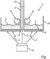
Dabei zeigt die einzige Fig. eine schematische Schnittansicht einer Vorrichtung zum additiven Herstellen eines Bauteils im Stereolithographieverfahren mit einem Behälter, in welchem ein flüssiges Grundmaterial aufgenommen ist, aus welchem durch Bestrahlung aufgrund von Polymerisation des Grundmaterials das Bauteil hergestellt wird.The only FIG. 1 shows a schematic sectional view of a device for additively producing a component in the stereolithography process with a container in which a liquid base material is received, from which the component is produced by irradiation due to polymerization of the base material.
In der einzigen Fig. ist eine Vorrichtung
Die Vorrichtung
Um eine besonders hohe Konturenschärfe des Bauteils
Zum Herstellen des insbesondere endlos ausgebildeten Bauteils
Um die Herstellung des Endlosbauteils
Das Bauteil
Bei der Vorrichtung
Insgesamt zeigt die Erfindung wie mittels der Vorrichtung
BezugszeichenlisteReference list
- 11
- Vorrichtungcontraption
- 22nd
- BauteilComponent
- 33rd
- GrundmaterialBasic material
- 44th
- Behältercontainer
- 55
- Bodenground
- 66
- StrahlungsquelleRadiation source
- 77
- Strahlungradiation
- 88th
- FördereinrichtungConveyor
- 99
- MaskierungMasking
- 1010th
- opaker Bereichopaque area
- 1111
- Öffnungopening
- 1212th
- Rohlingblank
ZITATE ENTHALTEN IN DER BESCHREIBUNG QUOTES INCLUDE IN THE DESCRIPTION
Diese Liste der vom Anmelder aufgeführten Dokumente wurde automatisiert erzeugt und ist ausschließlich zur besseren Information des Lesers aufgenommen. Die Liste ist nicht Bestandteil der deutschen Patent- bzw. Gebrauchsmusteranmeldung. Das DPMA übernimmt keinerlei Haftung für etwaige Fehler oder Auslassungen.This list of documents listed by the applicant has been generated automatically and is only included for better information for the reader. The list is not part of the German patent or utility model application. The DPMA assumes no liability for any errors or omissions.
Zitierte PatentliteraturPatent literature cited
- EP 2956822 B1 [0002]EP 2956822 B1 [0002]
Claims (5)
Translated fromGermanPriority Applications (1)
| Application Number | Priority Date | Filing Date | Title |
|---|---|---|---|
| DE102018127451.3ADE102018127451A1 (en) | 2018-11-05 | 2018-11-05 | Device and method for additive manufacturing of a component |
Applications Claiming Priority (1)
| Application Number | Priority Date | Filing Date | Title |
|---|---|---|---|
| DE102018127451.3ADE102018127451A1 (en) | 2018-11-05 | 2018-11-05 | Device and method for additive manufacturing of a component |
Publications (1)
| Publication Number | Publication Date |
|---|---|
| DE102018127451A1true DE102018127451A1 (en) | 2020-05-07 |
Family
ID=70469591
Family Applications (1)
| Application Number | Title | Priority Date | Filing Date |
|---|---|---|---|
| DE102018127451.3APendingDE102018127451A1 (en) | 2018-11-05 | 2018-11-05 | Device and method for additive manufacturing of a component |
Country Status (1)
| Country | Link |
|---|---|
| DE (1) | DE102018127451A1 (en) |
Cited By (1)
| Publication number | Priority date | Publication date | Assignee | Title |
|---|---|---|---|---|
| CN112590213A (en)* | 2021-03-04 | 2021-04-02 | 源秩科技(上海)有限公司 | Photocuring three-dimensional printing device and printing method |
Citations (4)
| Publication number | Priority date | Publication date | Assignee | Title |
|---|---|---|---|---|
| US5089184A (en)* | 1989-01-18 | 1992-02-18 | Mitsui Engineering And Shipbuilding Co., Ltd. | Optical molding method |
| US20160167301A1 (en)* | 2014-12-12 | 2016-06-16 | Autodesk, Inc. | Polymeric photoinitiators for 3d printing applications |
| EP2956822B1 (en) | 2013-02-12 | 2016-06-29 | CARBON3D, Inc. | Method and apparatus for three-dimensional fabrication with feed through carrier |
| DE102017213072A1 (en)* | 2016-09-05 | 2018-03-08 | Ford Global Technologies, Llc | Additive manufacturing process |
- 2018
- 2018-11-05DEDE102018127451.3Apatent/DE102018127451A1/enactivePending
Patent Citations (4)
| Publication number | Priority date | Publication date | Assignee | Title |
|---|---|---|---|---|
| US5089184A (en)* | 1989-01-18 | 1992-02-18 | Mitsui Engineering And Shipbuilding Co., Ltd. | Optical molding method |
| EP2956822B1 (en) | 2013-02-12 | 2016-06-29 | CARBON3D, Inc. | Method and apparatus for three-dimensional fabrication with feed through carrier |
| US20160167301A1 (en)* | 2014-12-12 | 2016-06-16 | Autodesk, Inc. | Polymeric photoinitiators for 3d printing applications |
| DE102017213072A1 (en)* | 2016-09-05 | 2018-03-08 | Ford Global Technologies, Llc | Additive manufacturing process |
Cited By (2)
| Publication number | Priority date | Publication date | Assignee | Title |
|---|---|---|---|---|
| CN112590213A (en)* | 2021-03-04 | 2021-04-02 | 源秩科技(上海)有限公司 | Photocuring three-dimensional printing device and printing method |
| CN112590213B (en)* | 2021-03-04 | 2021-06-25 | 源秩科技(上海)有限公司 | Photocuring three-dimensional printing device and printing method |
Similar Documents
| Publication | Publication Date | Title |
|---|---|---|
| EP2505341B1 (en) | Method for layered construction of a moulded part from highly viscous photopolymerisable material | |
| EP3093123B1 (en) | Method for producing a three-dimensional structure | |
| WO1994016875A1 (en) | Process and device for producing a three-dimensional object | |
| DE4125534A1 (en) | Three=dimensional layering - in which transparent sealed cover is used over bath to allow radiation through but exclude ambient atmos. | |
| DE69603880T2 (en) | METHOD FOR PRODUCING A COMPOSITE DISC AND DEVICE FOR APPLYING THIS METHOD | |
| DE19957370A1 (en) | Method and device for coating a substrate | |
| DE102015100731A1 (en) | OPTICAL MOLDING AND OPTICAL MOLDING PROCESS | |
| EP3277481B1 (en) | Method and device for the layered construction of a shaped part | |
| WO2015007770A1 (en) | Method and device for producing a three-dimensional object and exposure mask generating apparatus | |
| DE102015219866A1 (en) | Device and method for producing a three-dimensional object | |
| WO2016154645A1 (en) | Method and device for the layered construction of a shaped part | |
| DE102016213628A1 (en) | Device for additive manufacturing with optimized protective gas flow | |
| EP3022045A1 (en) | Method and device for producing a three-dimensional object and exposure mask generation device | |
| DE102009021418A1 (en) | Device and method for fixing a component to a component carrier | |
| DE102015225300A1 (en) | Methods and arrangements for reducing interfacial adhesion in photopolymerization | |
| DE102018127451A1 (en) | Device and method for additive manufacturing of a component | |
| DE102010028815A1 (en) | Method for encapsulating chip on substrate of chip module, involves hardening filling material and dam material, and adjusting partial hardening of dam material during laying dam materials on radiation device of applicator | |
| DE102016013317A1 (en) | Method for producing a three-dimensional molded article and device for carrying out the method | |
| DE69714972T2 (en) | Method of making a lens sheet | |
| AT522535B1 (en) | Stamp replication device and method for producing a holding device for a stamp replication device and a stamp | |
| DE102013222636A1 (en) | Method for applying a coating to workpieces and apparatus for coating workpieces | |
| DE102019002809A1 (en) | Method for producing at least one solid-state layer in accordance with predetermined geometric data | |
| DE112021004449T5 (en) | Production of an optical element | |
| DE102018127581A1 (en) | Device and method for additive manufacturing of a component | |
| DE4110903C2 (en) |
Legal Events
| Date | Code | Title | Description |
|---|---|---|---|
| R163 | Identified publications notified | ||
| R012 | Request for examination validly filed |