DE102018126728A1 - Method for assembling a wind turbine rotor blade - Google Patents
Method for assembling a wind turbine rotor bladeDownload PDFInfo
- Publication number
- DE102018126728A1 DE102018126728A1DE102018126728.2ADE102018126728ADE102018126728A1DE 102018126728 A1DE102018126728 A1DE 102018126728A1DE 102018126728 ADE102018126728 ADE 102018126728ADE 102018126728 A1DE102018126728 A1DE 102018126728A1
- Authority
- DE
- Germany
- Prior art keywords
- rotor blade
- wind turbine
- holding unit
- turbine rotor
- belt
- Prior art date
- Legal status (The legal status is an assumption and is not a legal conclusion. Google has not performed a legal analysis and makes no representation as to the accuracy of the status listed.)
- Withdrawn
Links
- 238000000034methodMethods0.000titleclaimsabstractdescription7
- 238000009434installationMethods0.000description2
- 230000001419dependent effectEffects0.000description1
- 239000011152fibreglassSubstances0.000description1
- 230000005484gravityEffects0.000description1
- 230000001012protectorEffects0.000description1
Images

Classifications
- F—MECHANICAL ENGINEERING; LIGHTING; HEATING; WEAPONS; BLASTING
- F03—MACHINES OR ENGINES FOR LIQUIDS; WIND, SPRING, OR WEIGHT MOTORS; PRODUCING MECHANICAL POWER OR A REACTIVE PROPULSIVE THRUST, NOT OTHERWISE PROVIDED FOR
- F03D—WIND MOTORS
- F03D1/00—Wind motors with rotation axis substantially parallel to the air flow entering the rotor
- F03D1/06—Rotors
- F03D1/065—Rotors characterised by their construction elements
- F03D1/0658—Arrangements for fixing wind-engaging parts to a hub
- F—MECHANICAL ENGINEERING; LIGHTING; HEATING; WEAPONS; BLASTING
- F03—MACHINES OR ENGINES FOR LIQUIDS; WIND, SPRING, OR WEIGHT MOTORS; PRODUCING MECHANICAL POWER OR A REACTIVE PROPULSIVE THRUST, NOT OTHERWISE PROVIDED FOR
- F03D—WIND MOTORS
- F03D13/00—Assembly, mounting or commissioning of wind motors; Arrangements specially adapted for transporting wind motor components
- F03D13/10—Assembly of wind motors; Arrangements for erecting wind motors
- F—MECHANICAL ENGINEERING; LIGHTING; HEATING; WEAPONS; BLASTING
- F05—INDEXING SCHEMES RELATING TO ENGINES OR PUMPS IN VARIOUS SUBCLASSES OF CLASSES F01-F04
- F05B—INDEXING SCHEME RELATING TO WIND, SPRING, WEIGHT, INERTIA OR LIKE MOTORS, TO MACHINES OR ENGINES FOR LIQUIDS COVERED BY SUBCLASSES F03B, F03D AND F03G
- F05B2230/00—Manufacture
- F05B2230/60—Assembly methods
- F05B2230/61—Assembly methods using auxiliary equipment for lifting or holding
- Y—GENERAL TAGGING OF NEW TECHNOLOGICAL DEVELOPMENTS; GENERAL TAGGING OF CROSS-SECTIONAL TECHNOLOGIES SPANNING OVER SEVERAL SECTIONS OF THE IPC; TECHNICAL SUBJECTS COVERED BY FORMER USPC CROSS-REFERENCE ART COLLECTIONS [XRACs] AND DIGESTS
- Y02—TECHNOLOGIES OR APPLICATIONS FOR MITIGATION OR ADAPTATION AGAINST CLIMATE CHANGE
- Y02E—REDUCTION OF GREENHOUSE GAS [GHG] EMISSIONS, RELATED TO ENERGY GENERATION, TRANSMISSION OR DISTRIBUTION
- Y02E10/00—Energy generation through renewable energy sources
- Y02E10/70—Wind energy
- Y02E10/72—Wind turbines with rotation axis in wind direction
- Y—GENERAL TAGGING OF NEW TECHNOLOGICAL DEVELOPMENTS; GENERAL TAGGING OF CROSS-SECTIONAL TECHNOLOGIES SPANNING OVER SEVERAL SECTIONS OF THE IPC; TECHNICAL SUBJECTS COVERED BY FORMER USPC CROSS-REFERENCE ART COLLECTIONS [XRACs] AND DIGESTS
- Y02—TECHNOLOGIES OR APPLICATIONS FOR MITIGATION OR ADAPTATION AGAINST CLIMATE CHANGE
- Y02P—CLIMATE CHANGE MITIGATION TECHNOLOGIES IN THE PRODUCTION OR PROCESSING OF GOODS
- Y02P70/00—Climate change mitigation technologies in the production process for final industrial or consumer products
- Y02P70/50—Manufacturing or production processes characterised by the final manufactured product
Landscapes
- Engineering & Computer Science (AREA)
- Life Sciences & Earth Sciences (AREA)
- Sustainable Development (AREA)
- Sustainable Energy (AREA)
- Chemical & Material Sciences (AREA)
- Combustion & Propulsion (AREA)
- Mechanical Engineering (AREA)
- General Engineering & Computer Science (AREA)
- Wind Motors (AREA)
Abstract
Translated fromGermanDescription
Translated fromGermanDie vorliegende Erfindung betrifft ein Verfahren zur Montage eines Windenergieanlagen-Rotorblattes sowie eine Halteeinheit zur Montage eines Windenergieanlagen-Rotorblattes.The present invention relates to a method for assembling a wind turbine rotor blade and a holding unit for assembling a wind turbine rotor blade.
Bei der Errichtung einer Windenergieanlage werden die Rotorblätter entweder einzeln oder zusammen mit dem aerodynamischen Rotor mittels eines Krans an einer Gondel der Windenergieanlage befestigt. Bei der Montage einzelner Rotorblätter wird das Rotorblatt mittels eines Kranes angehoben. Zur Sicherung des Rotorblattes während der Montage wird ein Halteseil an dem Rotorblatt befestigt. Nach Abschluss der Montage des Rotorblatts an einer Nabe der Windenergieanlage muss das Halteseil entfernt werden. Hierzu werden dann ein oder zwei Monteure zu dem Rotorblatt, beispielsweise mittels eines Mannkorbes, an dem Hauptkranhaken nach oben gezogen, um das Halteseil zu entfernen.When erecting a wind turbine, the rotor blades are attached to a nacelle of the wind turbine either individually or together with the aerodynamic rotor by means of a crane. When assembling individual rotor blades, the rotor blade is lifted using a crane. To secure the rotor blade during assembly, a tether is attached to the rotor blade. After the installation of the rotor blade on a hub of the wind turbine has been completed, the tether must be removed. For this purpose, one or two fitters are then pulled up to the rotor blade, for example by means of a man basket, on the main crane hook in order to remove the tether.
Alternativ dazu sind fernauslösbare Halteseile bekannt. Diese erfordern jedoch einen Eingriff in das Design des Rotorblattes, wodurch das Rotorblatt aufwendiger und teurer wird.Alternatively, remotely releasable tether cables are known. However, these require an intervention in the design of the rotor blade, which makes the rotor blade more complex and expensive.
Es ist eine Aufgabe der vorliegenden Erfindung eine Montage eines Windenergieanlagen-Rotorblattes zu vereinfachen. Insbesondere ist es Aufgabe der vorliegenden Erfindung eine Demontage eines Halteseils zu vereinfachen.It is an object of the present invention to simplify the assembly of a wind turbine rotor blade. In particular, it is an object of the present invention to simplify disassembly of a tether.
Diese Aufgabe wird durch ein Verfahren zur Montage eines Windenergieanlagen-Rotorblattes nach Anspruch 1 sowie durch eine Halteeinheit zur Montage eines Rotorblattes nach Anspruch 3 gelöst.This object is achieved by a method for assembling a wind turbine rotor blade according to claim 1 and by a holding unit for assembling a rotor blade according to claim 3.
Somit wird ein Verfahren zur Montage eines Windenergieanlagen-Rotorblattes vorgesehen. Eine Halteeinheit wird lösbar außen an dem Rotorblatt ohne Eingriff in die Oberfläche des Rotorblattes befestigt. Ein Halteseil wird an der Halteeinheit befestigt. Das Rotorblatt wird an der Nabe der Windenergieanlage montiert, hierzu wird das Rotorblatt beispielsweise mittels eines Krans nach oben gezogen. Die Halteeinheit wird durch Pitchen des Rotorblattes gelöst.A method for assembling a wind turbine rotor blade is thus provided. A holding unit is releasably attached to the outside of the rotor blade without engaging in the surface of the rotor blade. A tether is attached to the tether. The rotor blade is mounted on the hub of the wind turbine, for this purpose the rotor blade is pulled up, for example by means of a crane. The holding unit is released by pitching the rotor blade.
Damit ist es möglich, das Halteseil von dem montierten Rotorblatt zu entfernen ohne dass dazu ein Monteur nach oben gezogen werden muss oder ohne dass hierzu eine fernauslösbare Entfernung des Halteseils erforderlich ist. Die Halteeinheit an der das Halteseil befestigt wird, wird lediglich durch Drehen bzw. Pitchen des Rotorblattes um die Längsachse des Rotorblattes gelöst.This makes it possible to remove the tether from the assembled rotor blade without a fitter having to be pulled upwards or without the need for a remotely releasable removal of the tether. The holding unit to which the tether is attached is released only by rotating or pitching the rotor blade around the longitudinal axis of the rotor blade.
Gemäß einem Aspekt der vorliegenden Erfindung weist die Halteeinheit mindestens einen Gurt auf, welcher mindestens einmal um das Rotorblatt gewickelt ist, um außen an dem Rotorblatt befestigt zu werden. An dem Gurt kann dann das Halteseil befestigt werden. Wenn die Montage des Rotorblattes erfolgt ist, dann muss lediglich das Rotorblatt gedreht werden, damit der Gurt, der um das Rotorblatt gewickelt ist, sich lösen bzw. entfernt werden kann.According to one aspect of the present invention, the holding unit has at least one belt which is wound around the rotor blade at least once in order to be fastened to the outside of the rotor blade. The tether can then be attached to the belt. Once the rotor blade has been assembled, the rotor blade only has to be rotated so that the belt which is wound around the rotor blade can be released or removed.
Die Erfindung betrifft ebenfalls eine Halteeinheit zur Montage eines Rotorblattes. Die Halteeinheit weist einen Gurt, wie beispielsweise einen Flachbandgurt und eine Klemmeinheit zum Beispiel in Form einer Klemmleiste auf. Die Klemmleiste ist dazu geeignet an einer Hinterkante des Rotorblattes befestigt zu werden. Zur Montage des Rotorblattes wird der Gurt mindestens einmal um das Rotorblatt gewickelt und ein Ende wird mittels der Klemmleiste an einer Hinterkante des Rotorblattes befestigt.The invention also relates to a holding unit for mounting a rotor blade. The holding unit has a belt, such as a flat belt and a clamping unit, for example in the form of a clamping strip. The terminal strip is suitable for being attached to a rear edge of the rotor blade. To assemble the rotor blade, the belt is wrapped around the rotor blade at least once and one end is fastened to a rear edge of the rotor blade by means of the clamping strip.
Gemäß einem weiteren Aspekt der vorliegenden Erfindung weist die Halteeinheit einen Aufleger als Schutz der Oberfläche des Rotorblattes zwischen der Oberfläche des Rotorblattes und dem Gurt auf.According to a further aspect of the present invention, the holding unit has a support to protect the surface of the rotor blade between the surface of the rotor blade and the belt.
Gemäß einem weiteren Aspekt der vorliegenden Erfindung kann die Klemmeinheit als ein glasfaserverstärkten Kunststoff GFK-Haken oder -Leiste ausgestaltet sein.According to a further aspect of the present invention, the clamping unit can be configured as a glass fiber reinforced plastic GRP hook or strip.
Gemäß einem weiteren Aspekt der vorliegenden Erfindung weist der Gurt eine rutschhemmende Oberfläche auf.According to a further aspect of the present invention, the belt has a non-slip surface.
Gemäß einem weiteren Aspekt der vorliegenden Erfindung ist ein Ende des Gurtes an der Klemmeinheit befestigt bzw. eingeklemmt und ein zweites Ende des Gurtes ist am Halteseil befestigt.According to a further aspect of the present invention, one end of the belt is attached or clamped to the clamping unit and a second end of the belt is attached to the tether.
Gemäß einem weiteren Aspekt der vorliegenden Erfindung ist die Klemmeinheit über ein Sicherungsseil an einem Kran oder dem Halteseil befestigt.According to a further aspect of the present invention, the clamping unit is fastened to a crane or the tether via a safety rope.
Weitere Ausgestaltungen der Erfindung sind Gegenstand der Unteransprüche.Further embodiments of the invention are the subject of the dependent claims.
Vorteile und Ausführungsbeispiele der Erfindung werden nachstehend unter Bezugnahme auf die Zeichnung näher erläutert.
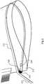
1 zeigt eine schematische Darstellung einer Windenergieanlage gemäß der Erfindung und2 zeigt eine schematische Darstellung eines Endes eines Rotorblattes gemäß einem Ausführungsbeispiel der Erfindung.
1 shows a schematic representation of a wind turbine according to the invention and2nd shows a schematic representation of one end of a rotor blade according to an embodiment of the invention.
Die Klemmleiste
Gemäß einem Aspekt der vorliegenden Erfindung kann der Gurt auf seiner Innenseite eine rutschhemmende Oberfläche aufweisen.According to one aspect of the present invention, the belt can have a non-slip surface on its inside.
Durch die Schwerkraft des Halteseiles und durch die Haltekräfte, welche auf das Halteseil ausgeübt wird (bei Einsatz einer elektrischen Winde, mindestens 200N) kann die Klemmeinheit permanent an die Hinterkante gedrückt werden, so dass das Halteseil formschlüssig am Rotorblatt befestigt ist.Due to the gravity of the tether and the holding forces that are exerted on the tether (when using an electric winch, at least 200N), the clamping unit can be pressed permanently against the rear edge, so that the tether is positively attached to the rotor blade.
Nach Abschluss der Montage des Rotorblattes kann die Halteeinheit
Optional kann die Klemmeinheit über ein Sicherungsseil mit dem Kranhaken verbunden sein, um sicherzustellen, dass die Klemmeinheit nicht ungehindert nach unten fallen kann.Optionally, the clamping unit can be connected to the crane hook via a safety rope to ensure that the clamping unit cannot fall down unhindered.
Optional kann eine externe bzw. modulare Steuereinheit vorgesehen sein, um das Pitchen der Rotorblätter zu ermöglichen, falls die Windenergieanlage noch nicht an das Energieversorgungsnetz angeschlossen ist.Optionally, an external or modular control unit can be provided to enable pitching of the rotor blades if the wind energy installation is not yet connected to the energy supply network.
Die erfindungsgemäße Halteeinheit ist vorteilhaft, weil der Gurt (insbesondere ein Flachgurt) durch das Umschlingen des Rotorblattes eine flächige Verteilung der Kräfte gewährleistet. Durch die Reibung des Gurtes an der Oberfläche des Rotorblattes wird ebenfalls die Klemmleiste wenig belastet.The holding unit according to the invention is advantageous because the belt (in particular a flat belt) ensures a flat distribution of the forces by looping around the rotor blade. Due to the friction of the belt on the surface of the rotor blade, the terminal strip is also little stressed.
Claims (9)
Translated fromGermanPriority Applications (5)
| Application Number | Priority Date | Filing Date | Title |
|---|---|---|---|
| DE102018126728.2ADE102018126728A1 (en) | 2018-10-26 | 2018-10-26 | Method for assembling a wind turbine rotor blade |
| EP19791247.0AEP3870835B1 (en) | 2018-10-26 | 2019-10-22 | Method for installing a wind turbine rotor blade |
| CN201980070552.0ACN112912619A (en) | 2018-10-26 | 2019-10-22 | Method for mounting a rotor blade of a wind energy plant |
| PCT/EP2019/078688WO2020083890A1 (en) | 2018-10-26 | 2019-10-22 | Method for installing a wind turbine rotor blade |
| US17/287,065US11466665B2 (en) | 2018-10-26 | 2019-10-22 | Method for installing a wind turbine rotor blade |
Applications Claiming Priority (1)
| Application Number | Priority Date | Filing Date | Title |
|---|---|---|---|
| DE102018126728.2ADE102018126728A1 (en) | 2018-10-26 | 2018-10-26 | Method for assembling a wind turbine rotor blade |
Publications (1)
| Publication Number | Publication Date |
|---|---|
| DE102018126728A1true DE102018126728A1 (en) | 2020-04-30 |
Family
ID=68318900
Family Applications (1)
| Application Number | Title | Priority Date | Filing Date |
|---|---|---|---|
| DE102018126728.2AWithdrawnDE102018126728A1 (en) | 2018-10-26 | 2018-10-26 | Method for assembling a wind turbine rotor blade |
Country Status (5)
| Country | Link |
|---|---|
| US (1) | US11466665B2 (en) |
| EP (1) | EP3870835B1 (en) |
| CN (1) | CN112912619A (en) |
| DE (1) | DE102018126728A1 (en) |
| WO (1) | WO2020083890A1 (en) |
Citations (5)
| Publication number | Priority date | Publication date | Assignee | Title |
|---|---|---|---|---|
| US5772269A (en)* | 1996-09-30 | 1998-06-30 | Mcconnell Douglas Corporation | Hoisting tool |
| EP1925583A1 (en)* | 2006-11-23 | 2008-05-28 | Siemens Aktiengesellschaft | Method of handling wind turbine blades and device for mounting wind turbine blades, in particular mounting blades on a wind turbine |
| DE102011116189B3 (en)* | 2011-06-21 | 2012-10-04 | Repower Systems Se | Load handling device for raising rotor blade of wind energy plant to mounting position, has support assembly having supporting surface projected in vertical plane to make contact of rotor blade or attaching element with support assembly |
| DE102014002228A1 (en)* | 2014-02-21 | 2015-08-27 | Spanset Secutex Sicherheitstechnik Gmbh | holder |
| CN105649893A (en)* | 2016-03-08 | 2016-06-08 | 中国船舶重工集团公司第七〇九研究所 | Dismounting system and method for blades of wind turbine |
Family Cites Families (13)
| Publication number | Priority date | Publication date | Assignee | Title |
|---|---|---|---|---|
| US2873226A (en)* | 1954-02-11 | 1959-02-10 | Distillers Co Yeast Ltd | Method of making glass reinforced plastic articles |
| US4569301A (en)* | 1984-01-04 | 1986-02-11 | Pyburn Robert M | Utility container for catamaran sailboats |
| WO2003104646A1 (en)* | 2002-06-05 | 2003-12-18 | Aloys Wobben | Rotor blade for a wind power plant |
| US20100139062A1 (en)* | 2009-02-25 | 2010-06-10 | General Electric Company | Lowering and raising a single wind turbine rotor blade from six-o'clock position |
| DE102011076937B3 (en)* | 2011-06-03 | 2012-12-06 | Aloys Wobben | Wind turbine rotor blade and method of assembling a wind turbine rotor blade |
| DE102011113482B4 (en)* | 2011-09-13 | 2013-04-18 | Nordex Energy Gmbh | Protective device for a rotor blade of a wind energy plant |
| CN103174601B (en)* | 2011-12-22 | 2015-05-27 | 华锐风电科技(集团)股份有限公司 | Fan blade protective sleeve |
| DE102013211751A1 (en)* | 2013-06-21 | 2014-12-24 | Wobben Properties Gmbh | Method for mounting a wind turbine rotor blade and wind turbine rotor blade |
| US9638163B2 (en)* | 2014-02-20 | 2017-05-02 | General Electric Company | Methods and systems for removing and/or installing wind turbine rotor blades |
| US9964095B2 (en)* | 2014-04-21 | 2018-05-08 | General Electric Company | Method and system for servicing wind turbine rotor |
| DE102014215969A1 (en)* | 2014-08-12 | 2016-02-18 | Wobben Properties Gmbh | Method for installing a rotor blade on a wind turbine |
| EP3351790B1 (en)* | 2017-01-20 | 2020-08-12 | Senvion GmbH | Traction sleeve for rotor blades of wind turbines |
| CN107059448A (en)* | 2017-06-06 | 2017-08-18 | 扬州兴轮绳缆有限公司 | A kind of protective jacket of hanging belt |
- 2018
- 2018-10-26DEDE102018126728.2Apatent/DE102018126728A1/ennot_activeWithdrawn
- 2019
- 2019-10-22EPEP19791247.0Apatent/EP3870835B1/enactiveActive
- 2019-10-22USUS17/287,065patent/US11466665B2/enactiveActive
- 2019-10-22WOPCT/EP2019/078688patent/WO2020083890A1/ennot_activeCeased
- 2019-10-22CNCN201980070552.0Apatent/CN112912619A/enactivePending
Patent Citations (5)
| Publication number | Priority date | Publication date | Assignee | Title |
|---|---|---|---|---|
| US5772269A (en)* | 1996-09-30 | 1998-06-30 | Mcconnell Douglas Corporation | Hoisting tool |
| EP1925583A1 (en)* | 2006-11-23 | 2008-05-28 | Siemens Aktiengesellschaft | Method of handling wind turbine blades and device for mounting wind turbine blades, in particular mounting blades on a wind turbine |
| DE102011116189B3 (en)* | 2011-06-21 | 2012-10-04 | Repower Systems Se | Load handling device for raising rotor blade of wind energy plant to mounting position, has support assembly having supporting surface projected in vertical plane to make contact of rotor blade or attaching element with support assembly |
| DE102014002228A1 (en)* | 2014-02-21 | 2015-08-27 | Spanset Secutex Sicherheitstechnik Gmbh | holder |
| CN105649893A (en)* | 2016-03-08 | 2016-06-08 | 中国船舶重工集团公司第七〇九研究所 | Dismounting system and method for blades of wind turbine |
Also Published As
| Publication number | Publication date |
|---|---|
| WO2020083890A1 (en) | 2020-04-30 |
| US11466665B2 (en) | 2022-10-11 |
| EP3870835C0 (en) | 2023-11-08 |
| CN112912619A (en) | 2021-06-04 |
| US20210355914A1 (en) | 2021-11-18 |
| EP3870835A1 (en) | 2021-09-01 |
| EP3870835B1 (en) | 2023-11-08 |
Similar Documents
| Publication | Publication Date | Title |
|---|---|---|
| EP1592882B1 (en) | Method for mounting a rotor blade of a wind energy installation without using a crane | |
| DE10305543C5 (en) | Method for assembling rotor blades and a rotor blade for a wind energy plant | |
| EP2715114B1 (en) | Wind turbine rotor blade and method for installing a wind turbine rotor blade | |
| EP3011169B1 (en) | Method for mounting a wind turbine rotor blade, and wind turbine rotor blade | |
| EP3377758B1 (en) | Wind turbine rotor blade and wind turbine | |
| EP2550225B1 (en) | Lifting unit for lifting of a rotor of a windturbine | |
| EP3514099B1 (en) | Device for fixing a crane or guidance cable on a rotor blade of a wind energy system | |
| DE102008033857A1 (en) | Rotor blade mounting device for wind turbine, has pivoting mechanism fixed in area of pivoting point of frame and pivotable at ninety degrees around frame, where pivoting mechanism has structure for retaining crane hook | |
| DE102006008428B4 (en) | Assembly / disassembly of a rotor blade | |
| DE102004045415C5 (en) | Device for identifying a wind energy plant | |
| EP3942175B1 (en) | Method for installing rotor blades of a wind turbine | |
| DE19826086A1 (en) | Rotor blade for wind power generators and rotor blade manufacture | |
| EP3781808B1 (en) | Wind turbine rotor blade and wind turbine | |
| EP3870835B1 (en) | Method for installing a wind turbine rotor blade | |
| EP3351790B1 (en) | Traction sleeve for rotor blades of wind turbines | |
| DE202012102170U1 (en) | Device for mounting / dismounting a component of a wind energy plant | |
| DE102018131443A1 (en) | Foundation arrangement, adapter element, tensioning device and tower of a wind energy installation and method for prestressing a tower of a wind energy installation | |
| DE102016102244A1 (en) | Method for mounting a wind turbine rotor blade and wind turbine rotor blade | |
| DE202016103896U1 (en) | Fastening device for a line | |
| DE102008052473A1 (en) | Wind power generator has horizontal rotor axis and gondola arranged on tower to rotate around vertical axis, where rotor blades are provided on hub, which are arranged to rotate or tilt to axis of rotor | |
| DE202008014000U1 (en) | Wind power engine with horizontal rotor axis | |
| DE102017007655A1 (en) | Adhesion device for rotor blades of wind turbines | |
| DE102017119243A1 (en) | Method for mounting a wind turbine rotor blade and wind turbine rotor blade |
Legal Events
| Date | Code | Title | Description |
|---|---|---|---|
| R163 | Identified publications notified | ||
| R120 | Application withdrawn or ip right abandoned |