DE102018123350A1 - Charging device for charging an electric vehicle - Google Patents
Charging device for charging an electric vehicleDownload PDFInfo
- Publication number
- DE102018123350A1 DE102018123350A1DE102018123350.7ADE102018123350ADE102018123350A1DE 102018123350 A1DE102018123350 A1DE 102018123350A1DE 102018123350 ADE102018123350 ADE 102018123350ADE 102018123350 A1DE102018123350 A1DE 102018123350A1
- Authority
- DE
- Germany
- Prior art keywords
- vehicle
- unit
- coupling
- contact
- designed
- Prior art date
- Legal status (The legal status is an assumption and is not a legal conclusion. Google has not performed a legal analysis and makes no representation as to the accuracy of the status listed.)
- Withdrawn
Links
- 230000008878couplingEffects0.000claimsabstractdescription152
- 238000010168coupling processMethods0.000claimsabstractdescription152
- 238000005859coupling reactionMethods0.000claimsabstractdescription152
- 230000006854communicationEffects0.000claimsdescription27
- 238000000034methodMethods0.000claimsdescription27
- 238000004891communicationMethods0.000claimsdescription26
- 238000006073displacement reactionMethods0.000claimsdescription14
- 238000004140cleaningMethods0.000claimsdescription13
- XLYOFNOQVPJJNP-UHFFFAOYSA-NwaterSubstancesOXLYOFNOQVPJJNP-UHFFFAOYSA-N0.000claimsdescription5
- 230000001680brushing effectEffects0.000claimsdescription2
- 230000005540biological transmissionEffects0.000claims1
- 238000013459approachMethods0.000description6
- 238000013461designMethods0.000description5
- 238000003780insertionMethods0.000description4
- 230000037431insertionEffects0.000description4
- 238000004519manufacturing processMethods0.000description3
- 238000011109contaminationMethods0.000description2
- 238000011161developmentMethods0.000description2
- 230000018109developmental processEffects0.000description2
- 238000004146energy storageMethods0.000description2
- 238000012549trainingMethods0.000description2
- BUHVIAUBTBOHAG-FOYDDCNASA-N(2r,3r,4s,5r)-2-[6-[[2-(3,5-dimethoxyphenyl)-2-(2-methylphenyl)ethyl]amino]purin-9-yl]-5-(hydroxymethyl)oxolane-3,4-diolChemical compoundCOC1=CC(OC)=CC(C(CNC=2C=3N=CN(C=3N=CN=2)[C@H]2[C@@H]([C@H](O)[C@@H](CO)O2)O)C=2C(=CC=CC=2)C)=C1BUHVIAUBTBOHAG-FOYDDCNASA-N0.000description1
- 230000000712assemblyEffects0.000description1
- 238000000429assemblyMethods0.000description1
- 230000015572biosynthetic processEffects0.000description1
- 238000002485combustion reactionMethods0.000description1
- 230000001143conditioned effectEffects0.000description1
- 230000005611electricityEffects0.000description1
- 230000003993interactionEffects0.000description1
- 230000000149penetrating effectEffects0.000description1
- 238000003825pressingMethods0.000description1
- 230000001960triggered effectEffects0.000description1
Images


Classifications
- B—PERFORMING OPERATIONS; TRANSPORTING
- B60—VEHICLES IN GENERAL
- B60L—PROPULSION OF ELECTRICALLY-PROPELLED VEHICLES; SUPPLYING ELECTRIC POWER FOR AUXILIARY EQUIPMENT OF ELECTRICALLY-PROPELLED VEHICLES; ELECTRODYNAMIC BRAKE SYSTEMS FOR VEHICLES IN GENERAL; MAGNETIC SUSPENSION OR LEVITATION FOR VEHICLES; MONITORING OPERATING VARIABLES OF ELECTRICALLY-PROPELLED VEHICLES; ELECTRIC SAFETY DEVICES FOR ELECTRICALLY-PROPELLED VEHICLES
- B60L5/00—Current collectors for power supply lines of electrically-propelled vehicles
- B60L5/42—Current collectors for power supply lines of electrically-propelled vehicles for collecting current from individual contact pieces connected to the power supply line
- B—PERFORMING OPERATIONS; TRANSPORTING
- B60—VEHICLES IN GENERAL
- B60L—PROPULSION OF ELECTRICALLY-PROPELLED VEHICLES; SUPPLYING ELECTRIC POWER FOR AUXILIARY EQUIPMENT OF ELECTRICALLY-PROPELLED VEHICLES; ELECTRODYNAMIC BRAKE SYSTEMS FOR VEHICLES IN GENERAL; MAGNETIC SUSPENSION OR LEVITATION FOR VEHICLES; MONITORING OPERATING VARIABLES OF ELECTRICALLY-PROPELLED VEHICLES; ELECTRIC SAFETY DEVICES FOR ELECTRICALLY-PROPELLED VEHICLES
- B60L53/00—Methods of charging batteries, specially adapted for electric vehicles; Charging stations or on-board charging equipment therefor; Exchange of energy storage elements in electric vehicles
- B60L53/10—Methods of charging batteries, specially adapted for electric vehicles; Charging stations or on-board charging equipment therefor; Exchange of energy storage elements in electric vehicles characterised by the energy transfer between the charging station and the vehicle
- B60L53/12—Inductive energy transfer
- B60L53/126—Methods for pairing a vehicle and a charging station, e.g. establishing a one-to-one relation between a wireless power transmitter and a wireless power receiver
- B—PERFORMING OPERATIONS; TRANSPORTING
- B60—VEHICLES IN GENERAL
- B60L—PROPULSION OF ELECTRICALLY-PROPELLED VEHICLES; SUPPLYING ELECTRIC POWER FOR AUXILIARY EQUIPMENT OF ELECTRICALLY-PROPELLED VEHICLES; ELECTRODYNAMIC BRAKE SYSTEMS FOR VEHICLES IN GENERAL; MAGNETIC SUSPENSION OR LEVITATION FOR VEHICLES; MONITORING OPERATING VARIABLES OF ELECTRICALLY-PROPELLED VEHICLES; ELECTRIC SAFETY DEVICES FOR ELECTRICALLY-PROPELLED VEHICLES
- B60L53/00—Methods of charging batteries, specially adapted for electric vehicles; Charging stations or on-board charging equipment therefor; Exchange of energy storage elements in electric vehicles
- B60L53/10—Methods of charging batteries, specially adapted for electric vehicles; Charging stations or on-board charging equipment therefor; Exchange of energy storage elements in electric vehicles characterised by the energy transfer between the charging station and the vehicle
- B60L53/14—Conductive energy transfer
- B—PERFORMING OPERATIONS; TRANSPORTING
- B60—VEHICLES IN GENERAL
- B60L—PROPULSION OF ELECTRICALLY-PROPELLED VEHICLES; SUPPLYING ELECTRIC POWER FOR AUXILIARY EQUIPMENT OF ELECTRICALLY-PROPELLED VEHICLES; ELECTRODYNAMIC BRAKE SYSTEMS FOR VEHICLES IN GENERAL; MAGNETIC SUSPENSION OR LEVITATION FOR VEHICLES; MONITORING OPERATING VARIABLES OF ELECTRICALLY-PROPELLED VEHICLES; ELECTRIC SAFETY DEVICES FOR ELECTRICALLY-PROPELLED VEHICLES
- B60L53/00—Methods of charging batteries, specially adapted for electric vehicles; Charging stations or on-board charging equipment therefor; Exchange of energy storage elements in electric vehicles
- B60L53/30—Constructional details of charging stations
- B60L53/305—Communication interfaces
- B—PERFORMING OPERATIONS; TRANSPORTING
- B60—VEHICLES IN GENERAL
- B60L—PROPULSION OF ELECTRICALLY-PROPELLED VEHICLES; SUPPLYING ELECTRIC POWER FOR AUXILIARY EQUIPMENT OF ELECTRICALLY-PROPELLED VEHICLES; ELECTRODYNAMIC BRAKE SYSTEMS FOR VEHICLES IN GENERAL; MAGNETIC SUSPENSION OR LEVITATION FOR VEHICLES; MONITORING OPERATING VARIABLES OF ELECTRICALLY-PROPELLED VEHICLES; ELECTRIC SAFETY DEVICES FOR ELECTRICALLY-PROPELLED VEHICLES
- B60L53/00—Methods of charging batteries, specially adapted for electric vehicles; Charging stations or on-board charging equipment therefor; Exchange of energy storage elements in electric vehicles
- B60L53/30—Constructional details of charging stations
- B60L53/35—Means for automatic or assisted adjustment of the relative position of charging devices and vehicles
- B60L53/36—Means for automatic or assisted adjustment of the relative position of charging devices and vehicles by positioning the vehicle
- Y—GENERAL TAGGING OF NEW TECHNOLOGICAL DEVELOPMENTS; GENERAL TAGGING OF CROSS-SECTIONAL TECHNOLOGIES SPANNING OVER SEVERAL SECTIONS OF THE IPC; TECHNICAL SUBJECTS COVERED BY FORMER USPC CROSS-REFERENCE ART COLLECTIONS [XRACs] AND DIGESTS
- Y02—TECHNOLOGIES OR APPLICATIONS FOR MITIGATION OR ADAPTATION AGAINST CLIMATE CHANGE
- Y02T—CLIMATE CHANGE MITIGATION TECHNOLOGIES RELATED TO TRANSPORTATION
- Y02T10/00—Road transport of goods or passengers
- Y02T10/60—Other road transportation technologies with climate change mitigation effect
- Y02T10/70—Energy storage systems for electromobility, e.g. batteries
- Y—GENERAL TAGGING OF NEW TECHNOLOGICAL DEVELOPMENTS; GENERAL TAGGING OF CROSS-SECTIONAL TECHNOLOGIES SPANNING OVER SEVERAL SECTIONS OF THE IPC; TECHNICAL SUBJECTS COVERED BY FORMER USPC CROSS-REFERENCE ART COLLECTIONS [XRACs] AND DIGESTS
- Y02—TECHNOLOGIES OR APPLICATIONS FOR MITIGATION OR ADAPTATION AGAINST CLIMATE CHANGE
- Y02T—CLIMATE CHANGE MITIGATION TECHNOLOGIES RELATED TO TRANSPORTATION
- Y02T10/00—Road transport of goods or passengers
- Y02T10/60—Other road transportation technologies with climate change mitigation effect
- Y02T10/7072—Electromobility specific charging systems or methods for batteries, ultracapacitors, supercapacitors or double-layer capacitors
- Y—GENERAL TAGGING OF NEW TECHNOLOGICAL DEVELOPMENTS; GENERAL TAGGING OF CROSS-SECTIONAL TECHNOLOGIES SPANNING OVER SEVERAL SECTIONS OF THE IPC; TECHNICAL SUBJECTS COVERED BY FORMER USPC CROSS-REFERENCE ART COLLECTIONS [XRACs] AND DIGESTS
- Y02—TECHNOLOGIES OR APPLICATIONS FOR MITIGATION OR ADAPTATION AGAINST CLIMATE CHANGE
- Y02T—CLIMATE CHANGE MITIGATION TECHNOLOGIES RELATED TO TRANSPORTATION
- Y02T90/00—Enabling technologies or technologies with a potential or indirect contribution to GHG emissions mitigation
- Y02T90/10—Technologies relating to charging of electric vehicles
- Y02T90/12—Electric charging stations
- Y—GENERAL TAGGING OF NEW TECHNOLOGICAL DEVELOPMENTS; GENERAL TAGGING OF CROSS-SECTIONAL TECHNOLOGIES SPANNING OVER SEVERAL SECTIONS OF THE IPC; TECHNICAL SUBJECTS COVERED BY FORMER USPC CROSS-REFERENCE ART COLLECTIONS [XRACs] AND DIGESTS
- Y02—TECHNOLOGIES OR APPLICATIONS FOR MITIGATION OR ADAPTATION AGAINST CLIMATE CHANGE
- Y02T—CLIMATE CHANGE MITIGATION TECHNOLOGIES RELATED TO TRANSPORTATION
- Y02T90/00—Enabling technologies or technologies with a potential or indirect contribution to GHG emissions mitigation
- Y02T90/10—Technologies relating to charging of electric vehicles
- Y02T90/14—Plug-in electric vehicles
- Y—GENERAL TAGGING OF NEW TECHNOLOGICAL DEVELOPMENTS; GENERAL TAGGING OF CROSS-SECTIONAL TECHNOLOGIES SPANNING OVER SEVERAL SECTIONS OF THE IPC; TECHNICAL SUBJECTS COVERED BY FORMER USPC CROSS-REFERENCE ART COLLECTIONS [XRACs] AND DIGESTS
- Y02—TECHNOLOGIES OR APPLICATIONS FOR MITIGATION OR ADAPTATION AGAINST CLIMATE CHANGE
- Y02T—CLIMATE CHANGE MITIGATION TECHNOLOGIES RELATED TO TRANSPORTATION
- Y02T90/00—Enabling technologies or technologies with a potential or indirect contribution to GHG emissions mitigation
- Y02T90/10—Technologies relating to charging of electric vehicles
- Y02T90/16—Information or communication technologies improving the operation of electric vehicles
Landscapes
- Engineering & Computer Science (AREA)
- Power Engineering (AREA)
- Transportation (AREA)
- Mechanical Engineering (AREA)
- Computer Networks & Wireless Communication (AREA)
- Charge And Discharge Circuits For Batteries Or The Like (AREA)
- Electric Propulsion And Braking For Vehicles (AREA)
Abstract
Translated fromGerman
Description
Translated fromGermanTechnisches GebietTechnical field
Die vorliegende Erfindung betrifft eine Ladevorrichtung zum Laden eines Elektrofahrzeugs an einer Ladestation, welche insbesondere ein automatisches Laden beziehungsweise ein automatisches Verbinden des Elektrofahrzeugs mit einer Ladestation ermöglicht.The present invention relates to a charging device for charging an electric vehicle at a charging station, which in particular enables automatic charging or an automatic connection of the electric vehicle to a charging station.
Stand der TechnikState of the art
Bei der Verwendung von mit Batterien betriebenen Elektrofahrzeugen ist es notwendig, die im Elektrofahrzeug aufgenommenen Batterien, welche zur Versorgung des elektrischen Antriebs des Elektrofahrzeugs vorgesehen sind, zu laden, wenn die in der Batterie gespeicherte Energie zur Neige geht. Die jeweiligen Reichweiten der Elektrofahrzeuge und die jeweils gefahrene Kilometerzahl bedingen entsprechend den Bedarf nach mehr oder weniger häufigem Laden des Elektrofahrzeugs.When using electric vehicles powered by batteries, it is necessary to charge the batteries accommodated in the electric vehicle, which are provided to supply the electric drive of the electric vehicle, when the energy stored in the battery is running low. The respective ranges of the electric vehicles and the number of kilometers driven accordingly necessitate the need for more or less frequent charging of the electric vehicle.
In herkömmlichen Elektrofahrzeugen wird das Laden der Batterien darüber gelöst, dass das Elektrofahrzeug an einer Ladesäule oder einer Wallbox abgestellt wird und dann der Benutzer eine Verbindung zwischen der Ladesäule oder der Wallbox und dem Elektrofahrzeug durch ein händisch durchgeführtes Einstecken eines entsprechenden Ladekabels herstellt. Danach kann der eigentliche Ladevorgang gestartet werden.In conventional electric vehicles, the charging of the batteries is achieved by the electric vehicle being parked on a charging station or a wall box and then the user establishing a connection between the charging station or the wall box and the electric vehicle by manually inserting an appropriate charging cable. Then the actual loading process can be started.
Derzeit liegen die mit einer Batterieladung erreichbaren Reichweiten häufig noch noch unter den Reichweiten, die mit einer Tankfüllung eines herkömmlichen Fahrzeugs mit Verbrennungsmotor erzielbar sind, so dass die daraus ergebende Notwendigkeit des häufigeren Ladens für den Verbraucher als Komforteinbuße betrachtet werden kann.At present, the ranges that can be achieved with a battery charge are often still lower than the ranges that can be achieved with a tank filling of a conventional vehicle with an internal combustion engine, so that the resultant need for more frequent charging can be regarded as a loss of convenience for the consumer.
Um den Vorgang des Verbinden des Elektrofahrzeugs mit einer Ladesäule oder Wallbox zu automatisieren, und um auf diese Weise dann Zeit und Mühen des Benutzers einzusparen und den Komfort zu erhöhen, sind unterschiedliche Vorrichtungen zum automatisierten Verbinden von Elektrofahrzeugen mit Ladevorrichtungen bekannt.In order to automate the process of connecting the electric vehicle to a charging station or wall box, and in this way to save time and effort for the user and to increase comfort, various devices for the automated connection of electric vehicles to charging devices are known.
So ist beispielsweise aus der
Aus der
Darstellung der ErfindungPresentation of the invention
Ausgehend von dem bekannten Stand der Technik ist es eine Aufgabe der vorliegenden Erfindung, eine Ladevorrichtung zum Laden eines Elektrofahrzeugs, welche ein weiter vereinfachtes automatisches Kontaktieren des Fahrzeugs ermöglicht.On the basis of the known prior art, it is an object of the present invention to provide a charging device for charging an electric vehicle, which enables a further simplified automatic contacting of the vehicle.
Diese Aufgabe wird durch eine Ladevorrichtung mit den Merkmalen des Anspruchs 1 gelöst. Weiterbildungen ergeben sich aus den Unteransprüchen, der vorliegenden Beschreibung sowie den beigefügten Figuren.This object is achieved by a loading device with the features of
Entsprechend wird eine Ladevorrichtung zum Laden einer Traktionsbatterie eines Elektrofahrzeugs vorgeschlagen, umfassend eine Bodeneinheit, welche dazu ausgebildet und eingerichtet ist, im Bereich einer Fahrbahn für das Elektrofahrzeug angeordnet zu werden und einen Ladestrom bereit zu stellen, weiterhin umfassend eine Fahrzeugeinheit, welche dazu ausgebildet und eingerichtet ist, im Unterboden des Elektrofahrzeugs angeordnet zu werden und welche mit der Traktionsbatterie zur Zuführung eines Ladestroms verbunden ist, und weiterhin umfassend eine Kopplungsvorrichtung, welche dazu ausgebildet und eingerichtet ist, die Bodeneinheit und die Fahrzeugeinheit zur Übertragung eines Ladestroms elektrisch miteinander zu koppeln. Erfindungsgemäß ist die Kopplungsvorrichtung dazu ausgebildet und eingerichtet, dass das Koppeln durch eine Relativbewegung der Bodeneinheit und der Fahrzeugeinheit in Fahrzeuglängsrichtung erreicht wird.Accordingly, a charging device for charging a traction battery of an electric vehicle is proposed, comprising a floor unit which is designed and set up to be arranged in the area of a roadway for the electric vehicle and to provide a charging current, further comprising a vehicle unit which is designed and set up for this is to be arranged in the underbody of the electric vehicle and which is connected to the traction battery for supplying a charging current, and further comprising a coupling device which is designed and set up to electrically couple the floor unit and the vehicle unit to transmit a charging current. According to the invention, the coupling device is designed and set up such that the coupling is achieved by a relative movement of the floor unit and the vehicle unit in the longitudinal direction of the vehicle.
Dadurch, dass die Kopplungsvorrichtung so eingerichtet ist, dass das Koppeln der Bodeneinheit mit der Fahrzeugeinheit durch eine Relativbewegung der Bodeneinheit relativ zur Fahrzeugeinheit in der Fahrzeuglängsrichtung erfolgt, kann beim regulären Prozess des Einparkens beziehungsweise Abstellens eines Elektrofahrzeuges, welches sich in seiner Fahrzeuglängsrichtung bewegt, eine Kontaktierung hergestellt werden.Because the coupling device is set up in such a way that the floor unit is coupled to the vehicle unit by a relative movement of the floor unit relative to the vehicle unit in the vehicle longitudinal direction, contact can be made during the regular process of parking or parking an electric vehicle which is moving in its vehicle longitudinal direction getting produced.
Entsprechend sind zusätzliche Bewegungen des Elektrofahrzeugs zum Herstellen der Kontaktierung beziehungsweise zusätzliche Bewegungen des Kontaktierungselementes in anderen Richtungen nicht mehr notwendig.Corresponding are additional movements of the electric vehicle for establishing the contact or additional movements of the contacting element in other directions is no longer necessary.
Weiterhin ist durch die genannte Ausgestaltung eine besonders robuste Ausbildung der Kopplungsvorrichtung möglich, welche, aufgrund der reduzierten Notwendigkeiten an Bewegungen einfacher ausgebildet sein kann, als 3D Roboterarme oder andere aus dem Stand der Technik bekannte Kontaktierungsvorrichtungen.Furthermore, a particularly robust design of the coupling device is possible due to the above-mentioned configuration, which, due to the reduced need for movements, can be made simpler than 3D robot arms or other contacting devices known from the prior art.
Weiterhin ist es durch die Kopplung der Bodeneinheit mit der Fahrzeugeinheit durch eine Relativbewegung in Fahrzeuglängsrichtung möglich, die Kontakte in der Bodeneinheit oder in der Fahrzeugeinheit sowie in der Kopplungsvorrichtung in einer Ausrichtung vorzusehen, welche im wesentlichen in der Ebene des Fahrzeugunterbodens verläuft. Dadurch können die Kontakte weniger anfällig für die im Fahrzeugunterboden auftretenden Beanspruchungen beziehungsweise unempfindlicher gegen das Überfahren oder Betreten einer Anordnung am Boden ausgebildet werden.Furthermore, by coupling the floor unit to the vehicle unit by means of a relative movement in the longitudinal direction of the vehicle, it is possible to provide the contacts in the floor unit or in the vehicle unit and in the coupling device in an orientation which essentially runs in the plane of the vehicle underbody. As a result, the contacts can be made less susceptible to the stresses occurring in the vehicle underbody or less sensitive to being driven over or entering an arrangement on the floor.
Die Kopplungsvorrichtung ist dabei in einer bevorzugten Ausgestaltung in der Fahrzeugeinheit aufgenommen, wobei die Kopplungsvorrichtung einen Kopplungskontakt aufweist und dazu ausgebildet und eingerichtet ist, den Kopplungskontakt zur Kopplung mit einem Bodenkontaktbereich der Bodeneinheit abzusenken.In a preferred embodiment, the coupling device is accommodated in the vehicle unit, the coupling device having a coupling contact and being designed and set up to lower the coupling contact for coupling to a floor contact area of the floor unit.
Damit ergibt sich, dass das Elektrofahrzeug die Kopplungsvorrichtung stets mit sich führt und durch die ohnehin durch das Elektrofahrzeug ausgeführte Bewegung in Fahrzeuglängsrichtung die Kopplung zwischen der Kopplungseinheit und der Bodeneinheit hergestellt werden kann.The result of this is that the electric vehicle always carries the coupling device with it and the coupling between the coupling unit and the floor unit can be established by the movement in the longitudinal direction of the vehicle which is carried out by the electric vehicle anyway.
Aus dieser Ausgestaltung, bei der die Kopplungsvorrichtung in der Fahrzeugeinheit vorgesehen ist, ergibt sich weiterhin, dass in der Bodeneinheit keine beweglichen Teile vorgesehen sein müssen, sodass die Bodeneinheit besonders robust und kostengünstig ausgebildet werden kann. Dies ist beispielsweise dann von Bedeutung, wenn die Bodeneinheit auch in öffentlich zugänglichen Bereichen, beispielsweise in Parkbuchten am Straßenrand, vorgesehen sein soll. Entsprechend wird es ermöglicht, dass die Bodeneinheit dann aufgrund der robusten und kostengünstigen Ausbildung vielfältig vorgesehen sein kann und entsprechend eine nahezu flächendeckende Ladestruktur, welche ein automatisiertes Laden des Elektrofahrzeugs ermöglicht, denkbar ist.From this embodiment, in which the coupling device is provided in the vehicle unit, it also follows that no moving parts have to be provided in the floor unit, so that the floor unit can be made particularly robust and inexpensive. This is important, for example, if the floor unit is also to be provided in publicly accessible areas, for example in parking bays on the roadside. Accordingly, it is possible that the base unit can then be provided in a variety of ways due to the robust and cost-effective design, and accordingly an almost area-wide charging structure that enables automated charging of the electric vehicle is conceivable.
Bevorzugt kann die Kopplungsvorrichtung einen Kopplungsarm umfassen, der dazu ausgebildet und eingerichtet ist, den Kopplungskontakt abzusenken und mit dem Bodenkontaktbereich der Bodeneinheit zu koppeln, wobei der Kopplungsarm bevorzugt in Fahrzeugquerrichtung elastisch ausgebildet ist. So kann eine zuverlässige Kontaktierung erreicht werden.The coupling device can preferably comprise a coupling arm which is designed and set up to lower the coupling contact and to couple it to the ground contact region of the ground unit, the coupling arm preferably being designed to be elastic in the transverse direction of the vehicle. In this way, reliable contacting can be achieved.
In einer weiteren bevorzugten Ausführungsform weist die Bodeneinheit einen Bodenkontaktbereich auf, der dazu ausgebildet und eingerichtet ist, mit einem Kopplungskontakt der Kopplungsvorrichtung in elektrisch leitenden Kontakt gebracht zu werden, wobei der Bodenkontaktbereich bevorzugt in Form einer Kontaktschiene ausgebildet ist. Durch die Ausbildung des Bodenkontaktbereichs kann eine besonders robuste Herstellung der Kontaktierung erreicht werden.In a further preferred embodiment, the floor unit has a floor contact area which is designed and set up to be brought into electrically conductive contact with a coupling contact of the coupling device, the floor contact area preferably being in the form of a contact rail. A particularly robust production of the contact can be achieved by the formation of the ground contact area.
Besonders bevorzugt weist die Bodeneinheit einen Fangbereich auf, der dazu ausgebildet und eingerichtet ist, einen Kopplungskontakt der Kopplungsvorrichtung so zu leiten, dass er bei einer Relativbewegung zwischen der Bodeneinheit und der Fahrzeugeinheit in Fahrzeuglängsrichtung in den Bodenkontaktbereich eintritt. Damit kann auch bei einem Versatz ein zuverlässiges Kontaktieren ermöglicht werden.The floor unit particularly preferably has a catch area which is designed and set up to conduct a coupling contact of the coupling device in such a way that it enters the ground contact area in the longitudinal direction of the vehicle when there is a relative movement between the floor unit and the vehicle unit. This enables reliable contacting even in the event of an offset.
Die Kopplungsvorrichtung kann in einer Alternative in der Bodeneinheit aufgenommen sein, wobei die Kopplungsvorrichtung dann einen Kopplungskontakt aufweist und dazu ausgebildet und eingerichtet ist, den Kopplungskontakt zur Kopplung mit einem Fahrzeugkontaktbereich der Fahrzeugeinheit anzuheben. Damit wird eine alternative, zuverlässige und einfache automatische Kontaktierung möglich, bei der die Bodeneinheit nicht unter dem Fahrzeug angeordnet sein muss, sondern auch vor oder hinter dem Fahrzeug positioniert werden kann.In an alternative, the coupling device can be accommodated in the base unit, the coupling device then having a coupling contact and being designed and set up to raise the coupling contact for coupling to a vehicle contact area of the vehicle unit. This enables an alternative, reliable and simple automatic contacting, in which the floor unit does not have to be arranged under the vehicle, but can also be positioned in front of or behind the vehicle.
Bevorzugt umfasst die Kopplungsvorrichtung einen Verschiebungsarm, der dazu ausgebildet und eingerichtet ist, den Kopplungskontakt in Fahrzeuglängsrichtung zu bewegen und den Kopplungskontakt mit dem Fahrzeugkontaktbereich der Fahrzeugeinheit zu koppeln und wobei die Kopplungsvorrichtung einen Hubarm umfasst, der dazu ausgebildet und eingerichtet ist, den Kopplungskontakt anzuheben, wobei der Verschiebungsarm und/oder der Hubarm bevorzugt als Scherenarme ausgebildetThe coupling device preferably comprises a displacement arm which is designed and set up to move the coupling contact in the longitudinal direction of the vehicle and to couple the coupling contact to the vehicle contact area of the vehicle unit, and the coupling device comprises a lifting arm which is designed and set up to raise the coupling contact, wherein the displacement arm and / or the lifting arm are preferably designed as scissor arms
Durch die Ausbildung des Verschiebungsarms kann eine mechanisch robuste, kostengünstige und betriebssichere Ausbildung der Kopplungsvorrichtung erreicht werden.The design of the displacement arm enables a mechanically robust, inexpensive and reliable design of the coupling device.
Bevorzugt ist an der Bodeneinheit und/oder oder an der Fahrzeugeinheit eine Reinigungsvorrichtung vorgesehen, welcher vor dem eigentlichen Erstellen des Kontakts zwischen der Bodeneinheit und der Fahrzeugeinheit eine Reinigung der jeweiligen Bodenkontaktbereiche beziehungsweise Fahrzeugkontaktbereiche beziehungsweise Kopplungskontakts durchgeführt wird. Beispielsweise kann hier über das Bereitstellen eines starken Luftstroms, das Bereitstellen von mechanischen Reinigungsvorrichtungen wie beispielsweise einer Bürstvorrichtung oder des Aufbringens eines entsprechenden Wasserschwalls oder Wasserstrahls oder durch das vorherige Eindringen in die jeweiligen Kontaktbereiche durch eine Reinigungsmaske eine Reinigung erreicht werden.Preferably, a cleaning device is provided on the floor unit and / or on the vehicle unit, which cleans the respective floor contact areas or vehicle contact areas or before the contact between the floor unit and the vehicle unit is actually established Coupling contact is carried out. For example, cleaning can be achieved by providing a strong air flow, providing mechanical cleaning devices such as a brushing device or applying a corresponding water surge or water jet or by previously penetrating the respective contact areas using a cleaning mask.
Weiterhin kann eine Kommunikationsvorrichtung zur Herstellung einer Kommunikation zwischen der Bodeneinheit und der Fahrzeugeinheit vorgesehen sein, welche beispielsweise eine Authentifizierung für den vorgesehenen Ladevorgang ermöglicht sowie eine genauere Positionierung sowohl des Elektrofahrzeugs als auch der Kontaktierungsvorrichtung ermöglicht. Insbesondere kann über eine Kommunikation, welche die Annäherung des Elektrofahrzeugs beziehungsweise der Fahrzeugeinheit an die Bodeneinheit detektiert, entsprechend eine Betätigung der Reinigungsvorrichtung und/oder der Abdeckvorrichtung und/oder der Kopplungsvorrichtung angesteuert werden. Damit kann beispielsweise ein Annähern der Kopplungskontakte an den Bodenkontaktbereich und/oder an den Fahrzeugkontaktbereich eingeleitet werden, wenn sich die Fahrzeugeinheit in einem bestimmten Abstand von der Bodeneinheit befindet.Furthermore, a communication device for establishing communication between the floor unit and the vehicle unit can be provided, which, for example, enables authentication for the intended charging process and enables more precise positioning of both the electric vehicle and the contacting device. In particular, an actuation of the cleaning device and / or the covering device and / or the coupling device can be controlled accordingly via a communication which detects the approach of the electric vehicle or the vehicle unit to the floor unit. In this way, for example, the coupling contacts can be brought closer to the ground contact area and / or to the vehicle contact area if the vehicle unit is at a certain distance from the floor unit.
Bevorzugt ist eine Abdeckungsvorrichtung zum Abdecken des Bodenkontaktbereichs und/oder zum Abdecken des Fahrzeugkontaktbereichs und/oder zum Abdecken des Kopplungskontakts vorgesehen. Auf diese Weise kann eine Verschmutzung der Kontakte in den Zeiten vermieden oder zumindest verringert werden, in denen die Bodeneinheit nicht mit einer Fahrzeugeinheit gekoppelt ist.A covering device is preferably provided for covering the ground contact area and / or for covering the vehicle contact area and / or for covering the coupling contact. In this way, contamination of the contacts can be avoided or at least reduced in times when the floor unit is not coupled to a vehicle unit.
FigurenlisteFigure list
Bevorzugte weitere Ausführungsformen der Erfindung werden durch die nachfolgende Beschreibung der Figuren näher erläutert. Dabei zeigen:
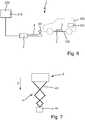
1 schematische Darstellung der Ladevorrichtung mit einer Bodeneinheit und einer Fahrzeugeinheit;2 eine schematische Draufsicht auf eine Bodeneinheit;3 eine schematische Seitenansicht der Fahrzeugeinheit in Kombination mit der Kopplungsvorrichtung und einer schematisch dargestellten Bodeneinheit;4 eine schematische, perspektivische Darstellung der Fahrzeugeinheit, der Bodeneinheit sowie der Kopplungsvorrichtung beim Prozess des Verbinden der Fahrzeugeinheit mit der Bodeneinheit;5 eine schematische, perspektivische Ansicht des Verbindungsvorganges in einem weiteren Ausführungsbeispiel, bei welchem ein leichter Versatz zwischen der Bodeneinheit und der Fahrzeugeinheit vorliegt;6 eine schematische Seitenansicht einer Ladevorrichtung in einer weiteren Ausgestaltung, bei welcher die Kopplungsvorrichtung in der Bodeneinheit vorgesehen ist;7 eine schematische Draufsicht auf die Ladevorrichtung gemäß6 , welche mit dem scherenförmigen Verschiebungsarm ausgebildet ist;8 eine schematische Seitenansicht der in den6 und7 gezeigten Ausführung;9 eine schematische Darstellung des Verbindungsvorganges zwischen der Fahrzeugeinheit und der Kontaktierungsvorrichtung der Bodeneinheit in einer weiteren Ausgestaltung;10 eine schematische Unteransicht der Bodeneinheit sowie der Fahrzeugeinheit und der in der Bodeneinheit aufgenommenem Kopplungsvorrichtung in einer schematischen Darstellung, wobei die Kopplungsvorrichtung noch in der Bodeneinheit vollständig aufgenommen ist und entsprechend ein Ladevorgang noch nicht begonnen hat;11 eine schematische Darstellung aus10 , jedoch nun mit ausgefahrener Kopplungsvorrichtung, welche die Bodeneinheit mit der Fahrzeugeinheit elektrisch verbindet.
1 schematic representation of the loading device with a floor unit and a vehicle unit;2nd a schematic plan view of a floor unit;3rd a schematic side view of the vehicle unit in combination with the coupling device and a schematically shown floor unit;4th is a schematic, perspective view of the vehicle unit, the floor unit and the coupling device in the process of connecting the vehicle unit to the floor unit;5 a schematic, perspective view of the connection process in a further embodiment, in which there is a slight offset between the floor unit and the vehicle unit;6 is a schematic side view of a loading device in a further embodiment, in which the coupling device is provided in the base unit;7 a schematic plan view of the loading device according to6 , which is formed with the scissor-shaped displacement arm;8th is a schematic side view of the in the6 and7 shown execution;9 a schematic representation of the connection process between the vehicle unit and the contacting device of the floor unit in a further embodiment;10th a schematic bottom view of the floor unit and the vehicle unit and the coupling device accommodated in the floor unit in a schematic representation, wherein the coupling device is still completely accommodated in the floor unit and accordingly a charging process has not yet begun;11 a schematic representation10th , but now with the coupling device extended, which electrically connects the floor unit to the vehicle unit.
Detaillierte Beschreibung bevorzugter AusführungsbeispieleDetailed description of preferred embodiments
Im Folgenden werden bevorzugte Ausführungsbeispiele anhand der Figuren beschrieben. Dabei werden gleiche, ähnliche oder gleichwirkende Elemente in den unterschiedlichen Figuren mit identischen Bezugszeichen versehen, und auf eine wiederholte Beschreibung dieser Elemente wird teilweise verzichtet, um Redundanzen zu vermeiden.Preferred exemplary embodiments are described below with reference to the figures. Identical, similar or equivalent elements in the different figures are provided with identical reference numerals, and a repeated description of these elements is partially omitted in order to avoid redundancies.
In
Die Ladevorrichtung
Die Bodeneinheit
Die Bodeneinheit
Die Bodeneinheit
In der Ladeeinheit
In dem in
Die Ladeeinheit
In einer anderen Weiterbildung sind Baugruppen der Ladeeinheit
Die Ladevorrichtung
Die Fahrzeugeinheit
Die Fahrzeugeinheit
Eine Kopplungsvorrichtung
Die Kopplungsvorrichtung
Mit anderen Worten findet eine Kontaktierung zwischen der Fahrzeugeinheit
Mit anderen Worten führt die Bewegung des Elektroautos
In
Der Bodenkontaktbereich
Die Bodeneinheit
Der durch die Leitflächen
Mit anderen Worten ist es möglich, durch eine Relativbewegung der Fahrzeugeinheit
Die Bodeneinheit
Insbesondere ist es auch vorgesehen, die Bodeneinheit
Die Bodeneinheit
Bevorzugt ist eine nur schematisch angedeutete Reinigungsvorrichtung
Um eine Verschmutzung des Bodenkontaktbereichs
Um eine Verschmutzung des Kopplungskontakts
Um eine Kommunikation zwischen dem Elektrofahrzeug
Durch die durch die Kommunikationsmodule
Die Kommunikationsvorrichtung kann darüber hinaus auch beispielsweise Leuchtdioden umfassen, welche in vorgegebenen Bereichen der Bodeneinheit
In den
Ein Kopplungsarm
Auf diese Weise ist es möglich, beim Einfahren des Elektrofahrzeugs
Das Verfahren zur Herstellung einer elektrischen Verbindung kann auch wie folgt beschrieben werden:The method for establishing an electrical connection can also be described as follows:
VerbindenConnect
Bei der Annährung der Fahrzeugeinheit
Gleichzeitig wird auch eine Abdeckungsvorrichtung
Das Elektrofahrzeug
Sobald sich der Kopplungskontakt
Sollte sich der Kopplungskontakt
Der Kopplungskontakt
Sobald die Kontaktierung hergestellt wurde wird der Fahrer darüber informiert. Das System ist dabei so ausgelegt, dass es noch möglich ist, bis zu 50 cm nach der ersten Kontaktierung weiterzufahren, um ein Abreißen der Kopplungsvorrichtung zu vermeiden. Das Elektrofahrzeug wird dabei bevorzugt automatisch elektrisch abgebremst.As soon as contact is established, the driver will be informed. The system is designed so that it is still possible to continue up to 50 cm after the first contact in order to avoid tearing off the coupling device. The electric vehicle is preferably automatically braked electrically.
LadevorgangCharging
Vor dem Beginn des Ladevorgangs wird das Elektrofahrzeug zunächst elektronisch gegen das Wegfahren gesichert.Before the charging process begins, the electric vehicle is first electronically secured against moving away.
Dann bekommt die Fahrzeugeinheit
Beendigung des LadevorgangsEnd of charging
Der Ladevorgang wird entweder automatisch beim Erreichen der vollständigen Ladung oder durch eine manuell vom Fahrer vorgegebenen Befehl beendet.The charging process is either ended automatically when the full charge is reached or by a command given manually by the driver.
In diesem Moment wird die Bereitstellung des Stroms unterbrochen und die Ladeleitungen potentialfrei geschaltet.At this moment, the supply of electricity is interrupted and the charging lines are isolated.
Da die physische Verbindung zwischen der Fahrzeugeinheit
Die Trennung der Verbindung von Fahrzeugeinheit
Sobald der Kopplungskontakt
Kommunikationcommunication
Die Kommunikationsvorrichtung
Verbindungsaufbau / Start LadevorgangEstablishing a connection / starting the charging process
Die Kommunikationsmodule
Sobald sich das Elektrofahrzeug
Dann wird automatisch die Anmeldung der Fahrzeugeinheit
Ist eine positive Anmeldung durchgeführt worden, können in der Bodeneinheit
Sobald sich das Elektrofahrzeug
In der Fahrzeugeinheit
Sobald der Kopplungskontakt
Verbindungsabbau / Stop LadevorgangDisconnection / stop charging
Der Ladevorgang wir unterbrochen sobald der Fahrer das Kommando an das Elektrofahrzeug
Die Fahrzeugeinheit
Wird erkannt, dass der Kopplungskontakt
Sobald über die Funkverbindung festgestellt wird, dass sich das Fahrzeug von der Bodeneinheit
In den
Die Ladevorrichtung
Weiterhin ist ebenfalls eine Bodeneinheit
In dem gezeigten Ausführungsbeispiel ist in der Fahrzeugeinheit
Die Bodeneinheit
Die Kopplungsvorrichtung
Der Kopplungskontakt
Der Fahrzeugkontaktbereich
In den
VerbindenConnect
Die Bodeneinheit
Der physikalische Verbindungprozess von Bodeneinheit
An der Fahrzeugeinheit
Mit Hilfe von Motoren an dem Verschiebungsarm
Mit Hilfe von Lichtsensoren am Kopplungskontakt
Dann wird der Kopplungskontakt
Der Ladeprozess wird im nachfolgend gestartet.The loading process is started in the following.
LadevorgangCharging
Sobald die Kontaktierung vollständig abgeschlossen ist, kann der Ladevorgang durch die Fahrzeugeinheit
Der Ladevorgang verläuft dann wie gewöhnlich.The charging process then proceeds as usual.
Die beiden Scherenarme können beim Ladevorgang freilagernd geschaltet werden, so dass das Fahrzeug auch während des Ladevorgangs Be- und Entladen werden kann.The two scissor arms can be switched freely during the loading process, so that the vehicle can be loaded and unloaded even during the loading process.
Beendigung des LadevorgangsEnd of charging
Der Ladevorgang wird durch eine Benutzereingabe oder automatisch beendet.The loading process is terminated by user input or automatically.
Die elektrische Verbindung zwischen der Fahrzeugeinheit
Anschließend werden die Scherenarme wieder aktiviert und der Kopplungskontakt
Die Scherenarme werden dann wieder eingefahren und eine Freigabe des Elektrofahrzeugs erfolgt erst dann, wenn die Scherenarme vollständig in der Bodeneinheit
Soweit anwendbar, können alle einzelnen Merkmale, die in den Ausführungsbeispielen dargestellt sind, miteinander kombiniert und/oder ausgetauscht werden, ohne den Bereich der Erfindung zu verlassen.As far as applicable, all individual features that are shown in the exemplary embodiments can be combined and / or exchanged with one another without leaving the scope of the invention.
BezugszeichenlisteReference list
- 11
- LadevorrichtungLoading device
- 100100
- ElektrofahrzeugElectric vehicle
- 110110
- TraktionsbatterieTraction battery
- 120120
- Unterboden des ElektrofahrzeugUnderbody of the electric vehicle
- 22nd
- BodeneinheitGround unit
- 2020th
- BodenkontaktbereichGround contact area
- 2222
- FangbereichCatch area
- 2424th
- LeitflächeGuide surface
- 2626
- DachbereichRoof area
- 33rd
- FahrzeugeinheitVehicle unit
- 3030th
- FahrzeugkontaktbereichVehicle contact area
- 3232
- FangbereichCatch area
- 3434
- LeitflächeGuide surface
- 44th
- KopplungsvorrichtungCoupling device
- 4040
- KopplungskontaktCoupling contact
- 4242
- VerschiebungsvorrichtungDisplacement device
- 4444
- Platteplate
- 4646
- HubvorrichtungLifting device
- 55
- ReinigungsvorrichtungCleaning device
- 60, 6260, 62
- KommunikationsvorrichtungCommunication device
- 77
- AbdeckungsvorrichtungCover device
- 88th
- AbdeckungsvorrichtungCover device
- XX
- FahrzeuglängsrichtungVehicle longitudinal direction
ZITATE ENTHALTEN IN DER BESCHREIBUNG QUOTES INCLUDE IN THE DESCRIPTION
Diese Liste der vom Anmelder aufgeführten Dokumente wurde automatisiert erzeugt und ist ausschließlich zur besseren Information des Lesers aufgenommen. Die Liste ist nicht Bestandteil der deutschen Patent- bzw. Gebrauchsmusteranmeldung. Das DPMA übernimmt keinerlei Haftung für etwaige Fehler oder Auslassungen.This list of documents listed by the applicant has been generated automatically and is only included for the better information of the reader. The list is not part of the German patent or utility model application. The DPMA assumes no liability for any errors or omissions.
Zitierte PatentliteraturPatent literature cited
- DE 102016008982 A1 [0006]DE 102016008982 A1 [0006]
- DE 102014226371 A1 [0007]DE 102014226371 A1 [0007]
Claims (10)
Translated fromGermanPriority Applications (2)
| Application Number | Priority Date | Filing Date | Title |
|---|---|---|---|
| DE102018123350.7ADE102018123350A1 (en) | 2018-09-21 | 2018-09-21 | Charging device for charging an electric vehicle |
| PCT/EP2019/075477WO2020058525A1 (en) | 2018-09-21 | 2019-09-23 | Charging device for charging an electric vehicle |
Applications Claiming Priority (1)
| Application Number | Priority Date | Filing Date | Title |
|---|---|---|---|
| DE102018123350.7ADE102018123350A1 (en) | 2018-09-21 | 2018-09-21 | Charging device for charging an electric vehicle |
Publications (1)
| Publication Number | Publication Date |
|---|---|
| DE102018123350A1true DE102018123350A1 (en) | 2020-03-26 |
Family
ID=68069753
Family Applications (1)
| Application Number | Title | Priority Date | Filing Date |
|---|---|---|---|
| DE102018123350.7AWithdrawnDE102018123350A1 (en) | 2018-09-21 | 2018-09-21 | Charging device for charging an electric vehicle |
Country Status (2)
| Country | Link |
|---|---|
| DE (1) | DE102018123350A1 (en) |
| WO (1) | WO2020058525A1 (en) |
Cited By (6)
| Publication number | Priority date | Publication date | Assignee | Title |
|---|---|---|---|---|
| WO2022084383A1 (en)* | 2020-10-20 | 2022-04-28 | Webasto SE | Charging device with emergency energy supply device, and method for an emergency energy supply |
| DE102021101023A1 (en) | 2021-01-19 | 2022-07-21 | Nussbaum Custom Lifts Gmbh | Automated parking system for vehicles |
| WO2022233881A1 (en)* | 2021-05-04 | 2022-11-10 | Easelink Gmbh | Ground contact unit |
| DE102021130777A1 (en) | 2021-11-24 | 2023-05-25 | Audi Aktiengesellschaft | Charging arrangement and method for charging an energy store of a motor vehicle with a charging robot |
| US12220999B2 (en) | 2022-03-07 | 2025-02-11 | Audi Ag | Conductive charging unit for a motor vehicle and method for controlling a conductive charging unit |
| DE102024001524A1 (en) | 2024-05-10 | 2025-07-31 | Mercedes-Benz Group AG | Charging device arrangement for charging an electrical energy storage device of a vehicle |
Families Citing this family (1)
| Publication number | Priority date | Publication date | Assignee | Title |
|---|---|---|---|---|
| CN113386595B (en)* | 2021-06-21 | 2024-01-23 | 武汉理工大学 | Contact type vehicle travelling charging device and charging method thereof |
Citations (19)
| Publication number | Priority date | Publication date | Assignee | Title |
|---|---|---|---|---|
| GB2185866A (en)* | 1985-12-20 | 1987-07-29 | City Wheels Ltd | Charging battery-powered vehicles |
| US5821731A (en)* | 1996-01-30 | 1998-10-13 | Sumitomo Wiring Systems, Ltd. | Connection system and connection method for an electric automotive vehicle |
| US20070131505A1 (en)* | 2005-07-16 | 2007-06-14 | Kim Bryan H J | Magnetic Induction Charging System for Vehicles |
| WO2010098397A1 (en)* | 2009-02-25 | 2010-09-02 | マスプロ電工株式会社 | Power supply system of mobile unit |
| US20100235006A1 (en)* | 2009-03-12 | 2010-09-16 | Wendell Brown | Method and Apparatus for Automatic Charging of an Electrically Powered Vehicle |
| US20110148350A1 (en)* | 2009-12-22 | 2011-06-23 | Hs Genion Gmbh | System for Charging a Battery in a Motor Vehicle |
| US20120286730A1 (en)* | 2011-05-11 | 2012-11-15 | Richard William Bonny | Automatic Recharging Robot for Electric and Hybrid Vehicles |
| DE102012217201A1 (en)* | 2011-10-06 | 2013-04-11 | Ford Global Technologies, Llc | VEHICLE GUIDANCE SYSTEM |
| US20140132208A1 (en)* | 2012-11-15 | 2014-05-15 | Delphi Technologies, Inc. | System and method to align a source resonator and a capture resonator for wireless electrical power transfer |
| DE102012007713B4 (en)* | 2011-04-20 | 2015-03-19 | SALT AND PEPPER Holding GmbH & Co. KG | Apparatus for electrically charging electrically driven road vehicles |
| DE102015111099A1 (en)* | 2014-07-24 | 2016-01-28 | Ford Global Technologies, Llc | Non-contact vehicle charging system |
| DE102014226371A1 (en)* | 2014-12-18 | 2016-06-23 | Robert Bosch Gmbh | Injection device for gaseous fuel |
| US9477893B2 (en)* | 2012-09-28 | 2016-10-25 | Siemens Aktiengesellschaft | Positioning system and method for positioning a vehicle |
| DE102016008982A1 (en)* | 2016-07-23 | 2017-02-16 | Daimler Ag | Charging device and method for the automatic conductive charging of an energy storage device of a motor vehicle |
| US9586491B2 (en)* | 2015-06-05 | 2017-03-07 | Nissan North America, Inc. | Vehicle wireless charging structure |
| US9660487B1 (en)* | 2016-06-13 | 2017-05-23 | Megau LLC | Intelligent wireless power transferring system with automatic positioning |
| US20180056799A1 (en)* | 2016-08-23 | 2018-03-01 | GM Global Technology Operations LLC | Hands-free conductive battery charger for an electric vehicle |
| US9944192B2 (en)* | 2015-11-13 | 2018-04-17 | Nio Usa, Inc. | Electric vehicle charging station system and method of use |
| DE102017218226A1 (en)* | 2017-03-20 | 2018-09-20 | Fraunhofer-Gesellschaft zur Förderung der angewandten Forschung e.V. | Underfloor contact system |
Family Cites Families (4)
| Publication number | Priority date | Publication date | Assignee | Title |
|---|---|---|---|---|
| DE102014200290A1 (en)* | 2014-01-10 | 2015-07-16 | Robert Bosch Gmbh | Electric charging device, electrical connection device, system and method for charging a battery of a vehicle |
| KR20180059534A (en)* | 2015-09-30 | 2018-06-04 | 볼보 트럭 코퍼레이션 | Car Charging Device |
| US10279696B2 (en)* | 2015-10-19 | 2019-05-07 | International Business Machines Corporation | Electric vehicle automatic charging station |
| CN107379998A (en)* | 2017-08-10 | 2017-11-24 | 尚圣杰 | A kind of electric automobile mobile charging single track from cruise brush electric system |
- 2018
- 2018-09-21DEDE102018123350.7Apatent/DE102018123350A1/ennot_activeWithdrawn
- 2019
- 2019-09-23WOPCT/EP2019/075477patent/WO2020058525A1/ennot_activeCeased
Patent Citations (19)
| Publication number | Priority date | Publication date | Assignee | Title |
|---|---|---|---|---|
| GB2185866A (en)* | 1985-12-20 | 1987-07-29 | City Wheels Ltd | Charging battery-powered vehicles |
| US5821731A (en)* | 1996-01-30 | 1998-10-13 | Sumitomo Wiring Systems, Ltd. | Connection system and connection method for an electric automotive vehicle |
| US20070131505A1 (en)* | 2005-07-16 | 2007-06-14 | Kim Bryan H J | Magnetic Induction Charging System for Vehicles |
| WO2010098397A1 (en)* | 2009-02-25 | 2010-09-02 | マスプロ電工株式会社 | Power supply system of mobile unit |
| US20100235006A1 (en)* | 2009-03-12 | 2010-09-16 | Wendell Brown | Method and Apparatus for Automatic Charging of an Electrically Powered Vehicle |
| US20110148350A1 (en)* | 2009-12-22 | 2011-06-23 | Hs Genion Gmbh | System for Charging a Battery in a Motor Vehicle |
| DE102012007713B4 (en)* | 2011-04-20 | 2015-03-19 | SALT AND PEPPER Holding GmbH & Co. KG | Apparatus for electrically charging electrically driven road vehicles |
| US20120286730A1 (en)* | 2011-05-11 | 2012-11-15 | Richard William Bonny | Automatic Recharging Robot for Electric and Hybrid Vehicles |
| DE102012217201A1 (en)* | 2011-10-06 | 2013-04-11 | Ford Global Technologies, Llc | VEHICLE GUIDANCE SYSTEM |
| US9477893B2 (en)* | 2012-09-28 | 2016-10-25 | Siemens Aktiengesellschaft | Positioning system and method for positioning a vehicle |
| US20140132208A1 (en)* | 2012-11-15 | 2014-05-15 | Delphi Technologies, Inc. | System and method to align a source resonator and a capture resonator for wireless electrical power transfer |
| DE102015111099A1 (en)* | 2014-07-24 | 2016-01-28 | Ford Global Technologies, Llc | Non-contact vehicle charging system |
| DE102014226371A1 (en)* | 2014-12-18 | 2016-06-23 | Robert Bosch Gmbh | Injection device for gaseous fuel |
| US9586491B2 (en)* | 2015-06-05 | 2017-03-07 | Nissan North America, Inc. | Vehicle wireless charging structure |
| US9944192B2 (en)* | 2015-11-13 | 2018-04-17 | Nio Usa, Inc. | Electric vehicle charging station system and method of use |
| US9660487B1 (en)* | 2016-06-13 | 2017-05-23 | Megau LLC | Intelligent wireless power transferring system with automatic positioning |
| DE102016008982A1 (en)* | 2016-07-23 | 2017-02-16 | Daimler Ag | Charging device and method for the automatic conductive charging of an energy storage device of a motor vehicle |
| US20180056799A1 (en)* | 2016-08-23 | 2018-03-01 | GM Global Technology Operations LLC | Hands-free conductive battery charger for an electric vehicle |
| DE102017218226A1 (en)* | 2017-03-20 | 2018-09-20 | Fraunhofer-Gesellschaft zur Förderung der angewandten Forschung e.V. | Underfloor contact system |
Cited By (6)
| Publication number | Priority date | Publication date | Assignee | Title |
|---|---|---|---|---|
| WO2022084383A1 (en)* | 2020-10-20 | 2022-04-28 | Webasto SE | Charging device with emergency energy supply device, and method for an emergency energy supply |
| DE102021101023A1 (en) | 2021-01-19 | 2022-07-21 | Nussbaum Custom Lifts Gmbh | Automated parking system for vehicles |
| WO2022233881A1 (en)* | 2021-05-04 | 2022-11-10 | Easelink Gmbh | Ground contact unit |
| DE102021130777A1 (en) | 2021-11-24 | 2023-05-25 | Audi Aktiengesellschaft | Charging arrangement and method for charging an energy store of a motor vehicle with a charging robot |
| US12220999B2 (en) | 2022-03-07 | 2025-02-11 | Audi Ag | Conductive charging unit for a motor vehicle and method for controlling a conductive charging unit |
| DE102024001524A1 (en) | 2024-05-10 | 2025-07-31 | Mercedes-Benz Group AG | Charging device arrangement for charging an electrical energy storage device of a vehicle |
Also Published As
| Publication number | Publication date |
|---|---|
| WO2020058525A1 (en) | 2020-03-26 |
Similar Documents
| Publication | Publication Date | Title |
|---|---|---|
| DE102018123350A1 (en) | Charging device for charging an electric vehicle | |
| DE102009023409B4 (en) | system for electrical energy transmission | |
| DE102015111099B4 (en) | Contactless vehicle charging system | |
| DE102018203162A1 (en) | Plug-in system for charging an electrical energy store | |
| EP3774437B1 (en) | Motor vehicle with an electric contacting unit | |
| DE102017205594B4 (en) | Robot device for establishing a charging connection between a charging device and an energy storage unit of a motor vehicle | |
| DE102019130551B4 (en) | Vehicle unit with a charging connection and charging system for charging a battery of an electric vehicle | |
| DE102018104759A1 (en) | Method and device for automatically connecting a charging connection with a charging connection receptacle of a vehicle, in particular a land vehicle | |
| EP3176024A1 (en) | Coupling module for the transmission of energy on a motor vehicle, motor vehicle with such a coupling module and energy transmission system for transmission of energy for a motor vehicle | |
| DE102009001080A1 (en) | Autonomous charging device for Plugln hybrid vehicles | |
| DE102019122051A1 (en) | Vehicle unit with a charging connection and charging device for charging a battery of an electric vehicle | |
| WO2016012173A1 (en) | Vehicle charging station comprising an articulated arm | |
| DE102015225986B4 (en) | A method for performing power supply operations between at least one power supply unit and a plurality of motor vehicles to be supplied with energy | |
| EP3092147A1 (en) | Electric charging device, electric connection device, system and method for charging a battery of a vehicle | |
| DE102009033235A1 (en) | Energy supply unit, land vehicle, exchange station and method for exchanging a power supply unit contained in a land vehicle | |
| WO2016012172A1 (en) | Vehicle charging station comprising a supply-contact device mounted on an arm | |
| DE102011114321A1 (en) | Method for electrically coupling car with charging station, involves moving car to position with respect to orientation aid so that plug device of car is brought to predetermined position with respect to plug socket of charging station | |
| DE102017009237A1 (en) | Loading device for the autonomous loading of a means of transport, and method for operating the loading device | |
| DE102013219444A1 (en) | Charging device for inductive charging | |
| DE102020207394A1 (en) | Charging device for electrically powered motor vehicles with a collecting funnel with a flap with a vehicle registration number | |
| DE102019007054A1 (en) | Charging device and method for automatically establishing an electrical connection between the charging device and a motor vehicle to be charged | |
| DE102020200292B4 (en) | Device and method for automatically charging an electrically powered motor vehicle | |
| DE102019115601A1 (en) | Charging device for charging a battery of a motor vehicle | |
| DE102022129145B3 (en) | Method for operating a charging station provided and designed for charging a traction battery of a motor vehicle with electrical energy, corresponding charging station and building arrangement with a charging station | |
| AT503549B1 (en) | SAFETY DEVICE FOR A TRACKED VEHICLE |
Legal Events
| Date | Code | Title | Description |
|---|---|---|---|
| R012 | Request for examination validly filed | ||
| R016 | Response to examination communication | ||
| R119 | Application deemed withdrawn, or ip right lapsed, due to non-payment of renewal fee |