DE102018117987A1 - electric motor - Google Patents
electric motorDownload PDFInfo
- Publication number
- DE102018117987A1 DE102018117987A1DE102018117987.1ADE102018117987ADE102018117987A1DE 102018117987 A1DE102018117987 A1DE 102018117987A1DE 102018117987 ADE102018117987 ADE 102018117987ADE 102018117987 A1DE102018117987 A1DE 102018117987A1
- Authority
- DE
- Germany
- Prior art keywords
- module
- heat
- electric motor
- motor
- base
- Prior art date
- Legal status (The legal status is an assumption and is not a legal conclusion. Google has not performed a legal analysis and makes no representation as to the accuracy of the status listed.)
- Pending
Links
- 238000009413insulationMethods0.000claimsdescription9
- 238000002485combustion reactionMethods0.000claimsdescription8
- 238000005304joiningMethods0.000claimsdescription6
- 238000005096rolling processMethods0.000claimsdescription5
- 238000006073displacement reactionMethods0.000claimsdescription4
- 238000005516engineering processMethods0.000claimsdescription3
- 239000002918waste heatSubstances0.000description11
- 238000000034methodMethods0.000description4
- 230000017525heat dissipationEffects0.000description3
- 238000003475laminationMethods0.000description2
- 229910052751metalInorganic materials0.000description2
- 239000002184metalSubstances0.000description2
- 238000000926separation methodMethods0.000description2
- 238000004804windingMethods0.000description2
- BUHVIAUBTBOHAG-FOYDDCNASA-N(2r,3r,4s,5r)-2-[6-[[2-(3,5-dimethoxyphenyl)-2-(2-methylphenyl)ethyl]amino]purin-9-yl]-5-(hydroxymethyl)oxolane-3,4-diolChemical compoundCOC1=CC(OC)=CC(C(CNC=2C=3N=CN(C=3N=CN=2)[C@H]2[C@@H]([C@H](O)[C@@H](CO)O2)O)C=2C(=CC=CC=2)C)=C1BUHVIAUBTBOHAG-FOYDDCNASA-N0.000description1
- 229910000831SteelInorganic materials0.000description1
- 229910052782aluminiumInorganic materials0.000description1
- XAGFODPZIPBFFR-UHFFFAOYSA-NaluminiumChemical compound[Al]XAGFODPZIPBFFR-UHFFFAOYSA-N0.000description1
- 238000010276constructionMethods0.000description1
- 238000001816coolingMethods0.000description1
- 238000013016dampingMethods0.000description1
- 230000000694effectsEffects0.000description1
- 238000001914filtrationMethods0.000description1
- 238000002955isolationMethods0.000description1
- 239000000463materialSubstances0.000description1
- 238000013021overheatingMethods0.000description1
- 238000005476solderingMethods0.000description1
- 239000010959steelSubstances0.000description1
- 238000011144upstream manufacturingMethods0.000description1
- 238000003466weldingMethods0.000description1
Images


Classifications
- H—ELECTRICITY
- H02—GENERATION; CONVERSION OR DISTRIBUTION OF ELECTRIC POWER
- H02K—DYNAMO-ELECTRIC MACHINES
- H02K11/00—Structural association of dynamo-electric machines with electric components or with devices for shielding, monitoring or protection
- H02K11/30—Structural association with control circuits or drive circuits
- H02K11/33—Drive circuits, e.g. power electronics
- H—ELECTRICITY
- H02—GENERATION; CONVERSION OR DISTRIBUTION OF ELECTRIC POWER
- H02K—DYNAMO-ELECTRIC MACHINES
- H02K5/00—Casings; Enclosures; Supports
- H02K5/04—Casings or enclosures characterised by the shape, form or construction thereof
- H02K5/16—Means for supporting bearings, e.g. insulating supports or means for fitting bearings in the bearing-shields
- H02K5/173—Means for supporting bearings, e.g. insulating supports or means for fitting bearings in the bearing-shields using bearings with rolling contact, e.g. ball bearings
- H02K5/1735—Means for supporting bearings, e.g. insulating supports or means for fitting bearings in the bearing-shields using bearings with rolling contact, e.g. ball bearings radially supporting the rotary shaft at only one end of the rotor
- H—ELECTRICITY
- H02—GENERATION; CONVERSION OR DISTRIBUTION OF ELECTRIC POWER
- H02K—DYNAMO-ELECTRIC MACHINES
- H02K5/00—Casings; Enclosures; Supports
- H02K5/04—Casings or enclosures characterised by the shape, form or construction thereof
- H02K5/22—Auxiliary parts of casings not covered by groups H02K5/06-H02K5/20, e.g. shaped to form connection boxes or terminal boxes
- H02K5/225—Terminal boxes or connection arrangements
- H—ELECTRICITY
- H02—GENERATION; CONVERSION OR DISTRIBUTION OF ELECTRIC POWER
- H02K—DYNAMO-ELECTRIC MACHINES
- H02K7/00—Arrangements for handling mechanical energy structurally associated with dynamo-electric machines, e.g. structural association with mechanical driving motors or auxiliary dynamo-electric machines
- H02K7/08—Structural association with bearings
- H02K7/085—Structural association with bearings radially supporting the rotary shaft at only one end of the rotor
- H—ELECTRICITY
- H02—GENERATION; CONVERSION OR DISTRIBUTION OF ELECTRIC POWER
- H02K—DYNAMO-ELECTRIC MACHINES
- H02K9/00—Arrangements for cooling or ventilating
- H02K9/22—Arrangements for cooling or ventilating by solid heat conducting material embedded in, or arranged in contact with, the stator or rotor, e.g. heat bridges
- H02K9/223—Heat bridges
- F—MECHANICAL ENGINEERING; LIGHTING; HEATING; WEAPONS; BLASTING
- F01—MACHINES OR ENGINES IN GENERAL; ENGINE PLANTS IN GENERAL; STEAM ENGINES
- F01L—CYCLICALLY OPERATING VALVES FOR MACHINES OR ENGINES
- F01L1/00—Valve-gear or valve arrangements, e.g. lift-valve gear
- F01L1/34—Valve-gear or valve arrangements, e.g. lift-valve gear characterised by the provision of means for changing the timing of the valves without changing the duration of opening and without affecting the magnitude of the valve lift
- F—MECHANICAL ENGINEERING; LIGHTING; HEATING; WEAPONS; BLASTING
- F01—MACHINES OR ENGINES IN GENERAL; ENGINE PLANTS IN GENERAL; STEAM ENGINES
- F01L—CYCLICALLY OPERATING VALVES FOR MACHINES OR ENGINES
- F01L13/00—Modifications of valve-gear to facilitate reversing, braking, starting, changing compression ratio, or other specific operations
- F01L2013/10—Auxiliary actuators for variable valve timing
- F01L2013/103—Electric motors
- H—ELECTRICITY
- H02—GENERATION; CONVERSION OR DISTRIBUTION OF ELECTRIC POWER
- H02K—DYNAMO-ELECTRIC MACHINES
- H02K9/00—Arrangements for cooling or ventilating
- H02K9/22—Arrangements for cooling or ventilating by solid heat conducting material embedded in, or arranged in contact with, the stator or rotor, e.g. heat bridges
- H02K9/227—Heat sinks
Landscapes
- Engineering & Computer Science (AREA)
- Power Engineering (AREA)
- Microelectronics & Electronic Packaging (AREA)
Abstract
Translated fromGerman
Description
Translated fromGermanDie Erfindung betrifft einen Elektromotor, der für die Verwendung in einem elektrischen Nockenwellenversteller oder in einem Mechanismus zur Verstellung des Kolbenhubs eines Verbrennungsmotors geeignet ist.The invention relates to an electric motor which is suitable for use in an electric camshaft adjuster or in a mechanism for adjusting the piston stroke of an internal combustion engine.
Ein Elektromotor für einen elektrischen Nockenwellenversteller ist beispielsweise aus der
Ein weiterer Elektromotor eines elektrischen Nockenwellenverstellers ist in der
Elektromotoren für eine solche Anwendung sind beispielsweise aus den Patenten
Einen Schritt weiter geht z.B. die
Der Erfindung liegt die Aufgabe zugrunde, für Nockenwellenversteller geeignete Elektromotoren dahingehend weiter zu entwickeln, dass Steuerungselektronik und Elektromotor eine Einheit bilden.The invention has for its object to further develop for camshaft adjuster suitable electric motors to the effect that control electronics and electric motor form a unit.
Diese Aufgabe wird erfindungsgemäß gelöst durch einen Elektromotor mit den Merkmalen des Anspruchs 1.This object is achieved by an electric motor with the features of claim 1.
Demnach weist der Elektromotor ein Basismotor-Modul und ein mit diesem elektrisch und mechanisch verbundenes Stecker-Modul auf, das als Elektronikmodul gestaltet ist. Das Elektronikmodul umfasst die Leistungselektronik, die Treiberelektronik und die Steuerelektronik, wobei das Elektronikmodul und das Basismotor-Modul Wärme über jeweils einen Wärmepfad abführen, wobei die Wärmepfade voneinander getrennt sind. Durch die Trennung der Wärmepfade kann die Abwärme vom Basismotor-Modul und Elektronikmodul separat in eine Wärmesenke der Umgebung geleitet werden. Die Abwärme des Elektromotors kann beispielsweise an den Motorblock oder ein andere umliegendes Bauteil abgegeben werden. Die Temperatur entspricht somit der Öltemperatur. Die Abwärme des Elektronikmoduls kann an die Umgebung abgeführt werden.Accordingly, the electric motor has a base motor module and a plug-in module which is electrically and mechanically connected thereto and which is designed as an electronic module. The electronics module comprises the power electronics, the driver electronics and the control electronics, wherein the electronic module and the base motor module dissipate heat via a respective heat path, wherein the heat paths are separated from each other. By separating the heat paths, the waste heat from the base engine module and electronics module can be routed separately into a heat sink of the environment. The waste heat of the electric motor can be delivered, for example, to the engine block or another surrounding component. The temperature thus corresponds to the oil temperature. The waste heat of the electronics module can be dissipated to the environment.
In einer vorteilhaften Ausführungsform führt das Basismotor-Modul Wärme über einen Wärmepfad
In einer vorteilhaften Ausführungsform besteht die Wärmeleitplatte aus einer ebenen Fläche und ist geeignet, an einem Bauteil, das an den Elektromotor angrenzt und die Wärmesenke bildet, zur Anlage gebracht zu werden. Das angrenzende Bauteil kann ein Steuertriebkastendeckel sein.In an advantageous embodiment, the heat conducting plate consists of a flat surface and is suitable for being brought into contact with a component which adjoins the electric motor and forms the heat sink. The adjacent component may be a timing case lid.
In einer vorteilhaften Ausführungsform weist das angrenzende Bauteil eine ebene Gegenfläche auf. Auf diese Weise kann die Wärmeleitfähigkeit zwischen den Bauteilen optimiert werden.In an advantageous embodiment, the adjacent component has a flat counter surface. In this way, the thermal conductivity between the components can be optimized.
In einer vorteilhaften Ausführungsform ist die Wärmeleitplatte als Teil einer Flanschplatte gestaltet, die mit dem Basismotor einen Pressverband und das Basismotor-Modul bildet. Das Basismotor-Modul umfasst somit den Basismotor und die Flanschplatte. Die Flanschpatte ist dazu geeignet, das Basismotor-Modul an einem umliegenden Bauteil zu befestigen und einen Wärmeleitpfad zwischen Basismotor und angrenzendem Bauteil zu bilden.In an advantageous embodiment, the heat conduction plate is designed as part of a flange plate, which forms a press fit and the base engine module with the base engine. The base engine module thus includes the base engine and the flange plate. The Flanschpatte is adapted to attach the base engine module to a surrounding component and to form a Wärmeleitpfad between base engine and adjacent component.
In einer vorteilhaften Ausführungsform umfasst das Elektronikmodul ein Elektronikgehäuse und führt Wärme über einen Wärmepfad
Eine weitergehende Trennung der Wärmepfade kann erreicht werden, indem die beiden Wärmepfade durch einen Isolationsraum voneinander getrennt verlaufen, wobei der Isolationsraum zwischen dem Basismotor-Modul und dem Elektronikmodul gebildet wird. A further separation of the heat paths can be achieved by the two heat paths run separated by an insulation space, wherein the insulation space between the base motor module and the electronic module is formed.
In einer vorteilhaften Ausführungsform umfasst das Basismotor-Modul einen Gehäusetopf, einen Stator und einen im Gehäusetopf mittels eines Wälzlagers gelagerten Rotor und ist in das Stecker-Modul eingefügt. Elektrische Verbindungen sind zwischen dem Stecker-Modul und dem Basismotor-Modul durch Verbindungen gegeben, welche durch Zusammenfügen der Module in deren Axialrichtung herstellbar sind. In einer Weiterentwicklung umfasst das Stecker-Modul eine mit dem Rotor zusammenwirkende Sensorplatine. In einer weiteren Weiterentwicklung sind die elektrischen Verbindungen zwischen dem Stecker-Modul und dem Basismotor-Modul als Schneidklemmverbindungen gebildet.In an advantageous embodiment, the base motor module comprises a housing pot, a stator and a rotor mounted in the housing pot by means of a rolling bearing and is inserted into the plug module. Electrical connections are made between the plug module and the base motor module by connections which can be made by assembling the modules in their axial direction. In a further development, the plug module comprises a sensor board cooperating with the rotor. In a further development, the electrical connections between the plug module and the base motor module are formed as insulation displacement connections.
Die Aufgabe wird ferner gelöst durch eine Elektromotoranordnung für einen variablen Ventiltrieb eines Verbrennungsmotors, wobei die Anordnung zwei Elektromotoren aufweist und wobei zumindest einer der zwei Elektromotoren nach einem der vorangehenden Ausführungsformen gestaltet ist. Die zwei Elektromotoren sind im Master-Slave-Betrieb verschaltet. Auf diese Weise kann eine Fail-safe-Funktion verwirklicht werden, indem ein Elektromotor die Steuerung auch des anderen Elektromotors übernimmt, sofern eine der Motorsteuerungen ausgefallen ist. Darüber hinaus ist es denkbar, aus Kostengründen nur einen der Elektromotoren mit einer Steuereinheit auszustatten.The object is further achieved by an electric motor arrangement for a variable valve train of an internal combustion engine, wherein the arrangement comprises two electric motors and wherein at least one of the two electric motors is designed according to one of the preceding embodiments. The two electric motors are interconnected in master-slave mode. In this way, a fail-safe function can be realized by an electric motor takes over the control of the other electric motor, if one of the engine controls has failed. In addition, it is conceivable, for cost reasons, only equip one of the electric motors with a control unit.
Die Aufgabe wird ferner gelöst durch einen Bausatz, umfassend Module von Elektromotoren, nämlich ein einheitliches Basismotor-Modul und verschiedene, mit dem Basismotor-Modul kombinierbare Stecker-Module, welche sich hinsichtlich einer Sensorik (
Nachfolgend wird ein Ausführungsbeispiel der Erfindung anhand von Zeichnungen näher erläutert. Hierin zeigen:
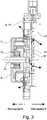
1 ein Set zum Zusammenbau von Elektromotoren, aufgebaut aus einem Basismotor-Modul und verschiedenen Stecker-Modulen,2 eine Darstellung des Elektromotors mit Basismodul und Elektonikmodul bzw. Steckmodul,3 eine Schnittdarstellung des Elektromotors mit zwei unabhängigen Wärmepfaden4 eine Schnittdarstellung des Elektromotors mit zwei unabhängigen Wärmepfaden vor dem Fügen der zwei Module.
1 a kit for assembling electric motors, consisting of a basic engine module and various plug modules,2 a representation of the electric motor with base module and electronics module or plug-in module,3 a sectional view of the electric motor with two independent heat paths4 a sectional view of the electric motor with two independent heat paths before joining the two modules.
Die
Der Bausatz
Insgesamt ist das Basismotor-Modul
Die Abwärme der Leistungselektronik und die Abwärme der Motorwicklungen werden über voneinander getrennten Wärmepfaden
Damit besitzt der Bausatz
Die Einfachheit der Montage wir durch eine Modularität des Systems erreicht, bei der der Basismotor in eine formgeometrisch variable Flanschplatte
Ermöglicht wird somit, die Motorsteuerung und den Motortreiber in einer baulichen Einheit in Form des Bausatzes
Damit die Abwärme aus den Elektromotorspulen keine zusätzliche thermische Belastung für die Steuerungs- und Treiberelektronik erzeugt, kann der Elektromotor
Dieser Wärmepfad
Besonders die Steuerelektronik, z.B. ein Mikroprozessor, ist wärmeempfindlich und muss ausreichend vor externem Wärmeeintrag geschützt und die eigene Abwärme abgeführt werden. Die Trennung der Wärmeabfuhr der beiden Wärmequellen
Nach aktuellem Stand der Technik werden hauptsächlich Schweiß- oder Löttechniken zur Herstellung der elektrischen Verbindung der Motorphasen mit den Zuleitungen eingesetzt. Das vorgeschlagene Konzept verwendet Schneidklemmkontakte zur Kontaktierung der Spulendrähte und Press-fit Technologie zur Anbindung an die Steuerplatine
Wenn ein zweiter, baugleicher oder ähnlicher Elektromotor
Ferner ist ein Operationsmodus möglich, bei dem zwei baugleiche Elektromotoren eingesetzt werden, welche sich gegenseitig auf korrekte Funktion überwachen. So kann im Fehlerfall das intakte System den anderen fehlerhaften Elektromotor vorübergehend ansteuern, während das fehlerhafte System neu startet. Sie stellen so gegenseitig den eigenen Betrieb mittels einfacher Redundanz sicher.Further, an operation mode is possible in which two identical electric motors are used, which monitor each other for correct function. Thus, in case of failure, the intact system can temporarily control the other faulty electric motor while the faulty system restarts. They thus ensure each other's own operation by means of simple redundancy.
BezugszeichenlisteLIST OF REFERENCE NUMBERS
- 11
- Bausatzkit
- 22
- Elektromotorelectric motor
- 33
- Basismotor-ModulBase engine module
- 44
- Stecker-ModulConnector module
- 55
- Stecker-ModulConnector module
- 66
- Stecker-ModulConnector module
- 77
- Gehäusecasing
- 88th
- Flanschplatteflange
- 99
- Luftraum als IsolationsraumAirspace as isolation room
- 1010
- Steuerplatinecontrol board
- 1111
- Statorblechpaketstator lamination
- 1212
- Elektronikgehäuseelectronics housing
- 1313
- Rotorrotor
- 1414
- Abtriebswelleoutput shaft
- 1515
- Rotorbodenrotor base
- 1616
- Permanentmagnetpermanent magnet
- 1717
- Wärmeleitplatteheat conduction
ZITATE ENTHALTEN IN DER BESCHREIBUNG QUOTES INCLUDE IN THE DESCRIPTION
Diese Liste der vom Anmelder aufgeführten Dokumente wurde automatisiert erzeugt und ist ausschließlich zur besseren Information des Lesers aufgenommen. Die Liste ist nicht Bestandteil der deutschen Patent- bzw. Gebrauchsmusteranmeldung. Das DPMA übernimmt keinerlei Haftung für etwaige Fehler oder Auslassungen.This list of the documents listed by the applicant has been generated automatically and is included solely for the better information of the reader. The list is not part of the German patent or utility model application. The DPMA assumes no liability for any errors or omissions.
Zitierte PatentliteraturCited patent literature
- DE 102013212933 B3 [0002, 0004]DE 102013212933 B3 [0002, 0004]
- US 8220426 B2 [0003, 0004]US 8220426 B2 [0003, 0004]
- US 2016/359434 A1 [0005]US 2016/359434 A1 [0005]
Claims (10)
Translated fromGermanPriority Applications (3)
| Application Number | Priority Date | Filing Date | Title |
|---|---|---|---|
| PCT/DE2019/100355WO2019206374A1 (en) | 2018-04-27 | 2019-04-17 | Electric motor |
| CN201980021018.0ACN111886785B (en) | 2018-04-27 | 2019-04-17 | Motor with a motor housing having a motor housing with a motor housing |
| US17/049,622US12046957B2 (en) | 2018-04-27 | 2019-04-17 | Electric motor |
Applications Claiming Priority (2)
| Application Number | Priority Date | Filing Date | Title |
|---|---|---|---|
| DE102018003446 | 2018-04-27 | ||
| DE102018003446.2 | 2018-04-27 |
Publications (1)
| Publication Number | Publication Date |
|---|---|
| DE102018117987A1true DE102018117987A1 (en) | 2019-10-31 |
Family
ID=68205436
Family Applications (1)
| Application Number | Title | Priority Date | Filing Date |
|---|---|---|---|
| DE102018117987.1APendingDE102018117987A1 (en) | 2018-04-27 | 2018-07-25 | electric motor |
Country Status (4)
| Country | Link |
|---|---|
| US (1) | US12046957B2 (en) |
| CN (1) | CN111886785B (en) |
| DE (1) | DE102018117987A1 (en) |
| WO (1) | WO2019206374A1 (en) |
Cited By (3)
| Publication number | Priority date | Publication date | Assignee | Title |
|---|---|---|---|---|
| WO2021197995A1 (en) | 2020-04-03 | 2021-10-07 | Sonceboz Mechatronics Boncourt Sa | Electric actuator |
| DE102020124216A1 (en) | 2020-09-17 | 2022-03-17 | Schaeffler Technologies AG & Co. KG | Housing with a heat shield for an electric motor |
| WO2022111763A1 (en)* | 2020-11-26 | 2022-06-02 | Schaeffler Technologies AG & Co. KG | Electric motor for an actuating device of a motor vehicle and method for mounting a camshaft adjuster |
Families Citing this family (4)
| Publication number | Priority date | Publication date | Assignee | Title |
|---|---|---|---|---|
| DE102019120913A1 (en)* | 2019-08-02 | 2021-02-04 | Schaeffler Technologies AG & Co. KG | Electric motor |
| DE102020117515A1 (en)* | 2020-07-02 | 2022-01-05 | Ebm-Papst St. Georgen Gmbh & Co. Kg | Centrifugal separator |
| DE102023132520A1 (en) | 2023-11-22 | 2025-05-22 | Schaeffler Technologies AG & Co. KG | Electric motor and method for assembling an electric motor |
| DE102023132519A1 (en) | 2023-11-22 | 2025-05-22 | Schaeffler Technologies AG & Co. KG | electric motor |
Family Cites Families (29)
| Publication number | Priority date | Publication date | Assignee | Title |
|---|---|---|---|---|
| US5763969A (en)* | 1996-11-14 | 1998-06-09 | Reliance Electric Industrial Company | Integrated electric motor and drive system with auxiliary cooling motor and asymmetric heat sink |
| DE19846220C2 (en)* | 1998-10-07 | 2001-11-29 | Mannesmann Sachs Ag | Cooling device for an electrical machine of a vehicle |
| DE10026424C2 (en) | 2000-05-29 | 2002-12-12 | Vera Feistkorn | Insulation displacement connection |
| US6586898B2 (en)* | 2001-05-01 | 2003-07-01 | Magnon Engineering, Inc. | Systems and methods of electric motor control |
| DE102004037991A1 (en) | 2003-11-27 | 2005-11-10 | Vera Feistkorn | Knife contact for retaining and making contact with an electrical conductor has a main body and two cutting slots |
| US7451738B2 (en)* | 2004-05-25 | 2008-11-18 | Perfect Motor Corp. | Turbocombustion engine |
| DE102005023202A1 (en)* | 2004-10-02 | 2006-09-07 | Schaeffler Kg | Phaser |
| CA2598967C (en)* | 2005-02-24 | 2010-10-05 | John W. Fitzgerald | Variable stroke premixed charge compression ignition engine |
| DE102006018590A1 (en) | 2006-04-21 | 2007-10-25 | Schaeffler Kg | handling device |
| JP4952653B2 (en) | 2007-06-04 | 2012-06-13 | 株式会社デンソー | Valve timing adjustment device |
| JP2009293576A (en)* | 2008-06-09 | 2009-12-17 | Hitachi Automotive Systems Ltd | Valve timing control device of internal combustion engine |
| DE102010003278A1 (en)* | 2010-03-25 | 2011-09-29 | Robert Bosch Gmbh | Drive unit for wiper system of car, has inner rotor comprising gearing, and driven shaft extending through rotor, where rotation speed of driven shaft and rotation speed of rotor are different from each other |
| JP5287787B2 (en) | 2010-04-16 | 2013-09-11 | 株式会社デンソー | Electric device |
| US9198328B1 (en)* | 2012-04-26 | 2015-11-24 | Hamilton Sundstrand Corporation | Thermal separation of electronic control chassis heatsink fins |
| US9467030B2 (en)* | 2013-03-15 | 2016-10-11 | Regal Beloit Australia Pty Ltd | Air-cooled electric machine and method of assembling the same |
| DE102013212933B3 (en) | 2013-07-03 | 2014-11-27 | Schaeffler Technologies Gmbh & Co. Kg | Bearing arrangement in an electric motor |
| ES2555121T3 (en)* | 2013-07-08 | 2015-12-29 | Fagor, S. Coop. | Electric drive device |
| DE102014215523A1 (en) | 2014-01-15 | 2015-07-16 | Schaeffler Technologies AG & Co. KG | roller bearing |
| DE102014205689A1 (en) | 2014-03-27 | 2015-10-01 | Schaeffler Technologies AG & Co. KG | Four point contact bearings |
| DE102014114129B4 (en)* | 2014-09-29 | 2016-06-02 | Beckhoff Automation Gmbh | driving device |
| WO2016065485A1 (en)* | 2014-10-31 | 2016-05-06 | Algozen Corporation | A mounting apparatus, for mounting at least one heat dissipating electrical device, optionally including a heat sink body for solid, gas and fluid heat exchange, and circuit board assembly providing interface between circuits |
| DE102015219149A1 (en)* | 2015-09-04 | 2017-03-09 | Brose Fahrzeugteile GmbH & Co. Kommanditgesellschaft, Würzburg | motor assembly |
| DE102015104246A1 (en)* | 2015-03-20 | 2016-09-22 | Ipgate Ag | Actuating device for a motor vehicle brake |
| US9998040B2 (en) | 2015-06-05 | 2018-06-12 | Denso Corporation | Motor driver of motor for valve timing control of internal combustion engine |
| JPWO2017033917A1 (en)* | 2015-08-27 | 2018-06-14 | 日本電産株式会社 | motor |
| CN205069616U (en)* | 2015-09-29 | 2016-03-02 | 比亚迪股份有限公司 | Power module and vehicle that has it |
| CN206099615U (en)* | 2016-09-30 | 2017-04-12 | 光陆机电有限公司 | High -efficient three -phase asynchronous motor |
| DE102017116249A1 (en) | 2017-07-19 | 2019-01-24 | Schaeffler Technologies AG & Co. KG | electric motor |
| CN107947452A (en)* | 2017-12-11 | 2018-04-20 | 徐州益利亚重工科技有限公司 | A kind of gear unit for motor vehicle |
- 2018
- 2018-07-25DEDE102018117987.1Apatent/DE102018117987A1/enactivePending
- 2019
- 2019-04-17CNCN201980021018.0Apatent/CN111886785B/enactiveActive
- 2019-04-17USUS17/049,622patent/US12046957B2/enactiveActive
- 2019-04-17WOPCT/DE2019/100355patent/WO2019206374A1/ennot_activeCeased
Cited By (4)
| Publication number | Priority date | Publication date | Assignee | Title |
|---|---|---|---|---|
| WO2021197995A1 (en) | 2020-04-03 | 2021-10-07 | Sonceboz Mechatronics Boncourt Sa | Electric actuator |
| FR3109034A1 (en) | 2020-04-03 | 2021-10-08 | Sonceboz Mechatronics Boncourt Sa | Electric actuator |
| DE102020124216A1 (en) | 2020-09-17 | 2022-03-17 | Schaeffler Technologies AG & Co. KG | Housing with a heat shield for an electric motor |
| WO2022111763A1 (en)* | 2020-11-26 | 2022-06-02 | Schaeffler Technologies AG & Co. KG | Electric motor for an actuating device of a motor vehicle and method for mounting a camshaft adjuster |
Also Published As
| Publication number | Publication date |
|---|---|
| CN111886785A (en) | 2020-11-03 |
| WO2019206374A1 (en) | 2019-10-31 |
| US20210242753A1 (en) | 2021-08-05 |
| CN111886785B (en) | 2023-11-07 |
| US12046957B2 (en) | 2024-07-23 |
Similar Documents
| Publication | Publication Date | Title |
|---|---|---|
| DE102018117987A1 (en) | electric motor | |
| DE102019120913A1 (en) | Electric motor | |
| DE102006034991B4 (en) | Electric power steering device | |
| EP1797286B1 (en) | Camshaft adjuster | |
| DE10130118C2 (en) | Carrier device for an electric motor, in particular for an electronically communicated direct current motor | |
| EP3616304B1 (en) | Electric drive unit with a housing | |
| DE102016200103A1 (en) | DRIVE DEVICE | |
| DE102016215166A1 (en) | Electric machine | |
| DE102015214201A1 (en) | ELECTRONIC DEVICE | |
| WO2019015720A1 (en) | ELECTRIC MOTOR | |
| DE102017103197A1 (en) | Electronics housing for an E-axis drive and E-axis with electronics housing | |
| DE102015013337A1 (en) | brakemotor | |
| DE102017220550A1 (en) | Cooling system for a drive system and vehicle drive system | |
| EP1010582A2 (en) | Electronic device | |
| DE102016201312A1 (en) | pump means | |
| DE102017118781A1 (en) | Drive unit for an actuator | |
| DE102020202364A1 (en) | Control device, in particular steering control device | |
| DE102021106888A1 (en) | Cooling system, electric power unit, electric vehicle and method of cooling an electric power unit | |
| DE112021001276T5 (en) | Brake fluid pressure control device and vehicle | |
| DE102019120912A1 (en) | Electric motor | |
| EP1921733B1 (en) | AC motor and controller | |
| DE202009008803U1 (en) | Electric machine | |
| EP3625878B1 (en) | Actuating device for an internal combustion engine | |
| DE102009054311A1 (en) | Valve device for an internal combustion engine | |
| EP2083607A1 (en) | Device for heating, in particular a motor vehicle |
Legal Events
| Date | Code | Title | Description |
|---|---|---|---|
| R012 | Request for examination validly filed |