DE102018116065A1 - Method for operating a self-propelled service device - Google Patents
Method for operating a self-propelled service deviceDownload PDFInfo
- Publication number
- DE102018116065A1 DE102018116065A1DE102018116065.8ADE102018116065ADE102018116065A1DE 102018116065 A1DE102018116065 A1DE 102018116065A1DE 102018116065 ADE102018116065 ADE 102018116065ADE 102018116065 A1DE102018116065 A1DE 102018116065A1
- Authority
- DE
- Germany
- Prior art keywords
- base station
- service device
- environment
- service
- user
- Prior art date
- Legal status (The legal status is an assumption and is not a legal conclusion. Google has not performed a legal analysis and makes no representation as to the accuracy of the status listed.)
- Withdrawn
Links
- 238000000034methodMethods0.000titleclaimsabstractdescription25
- 238000001514detection methodMethods0.000claimsabstractdescription56
- 238000003032molecular dockingMethods0.000claimsabstractdescription26
- 230000033001locomotionEffects0.000claimsabstractdescription15
- 238000004891communicationMethods0.000claimsdescription3
- 230000000007visual effectEffects0.000claimsdescription3
- 238000004140cleaningMethods0.000description17
- 238000013459approachMethods0.000description8
- 238000012544monitoring processMethods0.000description7
- 230000000694effectsEffects0.000description5
- 230000003287optical effectEffects0.000description5
- 238000009434installationMethods0.000description3
- 238000005259measurementMethods0.000description3
- 230000004044responseEffects0.000description2
- BUHVIAUBTBOHAG-FOYDDCNASA-N(2r,3r,4s,5r)-2-[6-[[2-(3,5-dimethoxyphenyl)-2-(2-methylphenyl)ethyl]amino]purin-9-yl]-5-(hydroxymethyl)oxolane-3,4-diolChemical compoundCOC1=CC(OC)=CC(C(CNC=2C=3N=CN(C=3N=CN=2)[C@H]2[C@@H]([C@H](O)[C@@H](CO)O2)O)C=2C(=CC=CC=2)C)=C1BUHVIAUBTBOHAG-FOYDDCNASA-N0.000description1
- 238000012937correctionMethods0.000description1
- 239000003550markerSubstances0.000description1
- 239000000463materialSubstances0.000description1
- 238000012552reviewMethods0.000description1
- 239000013589supplementSubstances0.000description1
- 230000001960triggered effectEffects0.000description1
- 238000002604ultrasonographyMethods0.000description1
Images


Classifications
- G—PHYSICS
- G05—CONTROLLING; REGULATING
- G05D—SYSTEMS FOR CONTROLLING OR REGULATING NON-ELECTRIC VARIABLES
- G05D1/00—Control of position, course, altitude or attitude of land, water, air or space vehicles, e.g. using automatic pilots
- G05D1/02—Control of position or course in two dimensions
- G05D1/021—Control of position or course in two dimensions specially adapted to land vehicles
- G05D1/0268—Control of position or course in two dimensions specially adapted to land vehicles using internal positioning means
- G05D1/0274—Control of position or course in two dimensions specially adapted to land vehicles using internal positioning means using mapping information stored in a memory device
- G—PHYSICS
- G05—CONTROLLING; REGULATING
- G05D—SYSTEMS FOR CONTROLLING OR REGULATING NON-ELECTRIC VARIABLES
- G05D1/00—Control of position, course, altitude or attitude of land, water, air or space vehicles, e.g. using automatic pilots
- G05D1/02—Control of position or course in two dimensions
- G05D1/021—Control of position or course in two dimensions specially adapted to land vehicles
- G05D1/0212—Control of position or course in two dimensions specially adapted to land vehicles with means for defining a desired trajectory
- G05D1/0214—Control of position or course in two dimensions specially adapted to land vehicles with means for defining a desired trajectory in accordance with safety or protection criteria, e.g. avoiding hazardous areas
- G—PHYSICS
- G01—MEASURING; TESTING
- G01C—MEASURING DISTANCES, LEVELS OR BEARINGS; SURVEYING; NAVIGATION; GYROSCOPIC INSTRUMENTS; PHOTOGRAMMETRY OR VIDEOGRAMMETRY
- G01C21/00—Navigation; Navigational instruments not provided for in groups G01C1/00 - G01C19/00
- G01C21/20—Instruments for performing navigational calculations
- G01C21/206—Instruments for performing navigational calculations specially adapted for indoor navigation
- G—PHYSICS
- G01—MEASURING; TESTING
- G01C—MEASURING DISTANCES, LEVELS OR BEARINGS; SURVEYING; NAVIGATION; GYROSCOPIC INSTRUMENTS; PHOTOGRAMMETRY OR VIDEOGRAMMETRY
- G01C21/00—Navigation; Navigational instruments not provided for in groups G01C1/00 - G01C19/00
- G01C21/38—Electronic maps specially adapted for navigation; Updating thereof
- G01C21/3804—Creation or updating of map data
- G01C21/3833—Creation or updating of map data characterised by the source of data
- G01C21/3837—Data obtained from a single source
- G—PHYSICS
- G01—MEASURING; TESTING
- G01S—RADIO DIRECTION-FINDING; RADIO NAVIGATION; DETERMINING DISTANCE OR VELOCITY BY USE OF RADIO WAVES; LOCATING OR PRESENCE-DETECTING BY USE OF THE REFLECTION OR RERADIATION OF RADIO WAVES; ANALOGOUS ARRANGEMENTS USING OTHER WAVES
- G01S17/00—Systems using the reflection or reradiation of electromagnetic waves other than radio waves, e.g. lidar systems
- G01S17/88—Lidar systems specially adapted for specific applications
- G01S17/93—Lidar systems specially adapted for specific applications for anti-collision purposes
- G01S17/931—Lidar systems specially adapted for specific applications for anti-collision purposes of land vehicles
- G—PHYSICS
- G05—CONTROLLING; REGULATING
- G05D—SYSTEMS FOR CONTROLLING OR REGULATING NON-ELECTRIC VARIABLES
- G05D1/00—Control of position, course, altitude or attitude of land, water, air or space vehicles, e.g. using automatic pilots
- G05D1/02—Control of position or course in two dimensions
- G05D1/021—Control of position or course in two dimensions specially adapted to land vehicles
- G05D1/0231—Control of position or course in two dimensions specially adapted to land vehicles using optical position detecting means
- G05D1/0246—Control of position or course in two dimensions specially adapted to land vehicles using optical position detecting means using a video camera in combination with image processing means
- A—HUMAN NECESSITIES
- A47—FURNITURE; DOMESTIC ARTICLES OR APPLIANCES; COFFEE MILLS; SPICE MILLS; SUCTION CLEANERS IN GENERAL
- A47L—DOMESTIC WASHING OR CLEANING; SUCTION CLEANERS IN GENERAL
- A47L2201/00—Robotic cleaning machines, i.e. with automatic control of the travelling movement or the cleaning operation
- A47L2201/04—Automatic control of the travelling movement; Automatic obstacle detection
- G—PHYSICS
- G01—MEASURING; TESTING
- G01S—RADIO DIRECTION-FINDING; RADIO NAVIGATION; DETERMINING DISTANCE OR VELOCITY BY USE OF RADIO WAVES; LOCATING OR PRESENCE-DETECTING BY USE OF THE REFLECTION OR RERADIATION OF RADIO WAVES; ANALOGOUS ARRANGEMENTS USING OTHER WAVES
- G01S17/00—Systems using the reflection or reradiation of electromagnetic waves other than radio waves, e.g. lidar systems
- G01S17/02—Systems using the reflection of electromagnetic waves other than radio waves
- G01S17/06—Systems determining position data of a target
- G01S17/46—Indirect determination of position data
- G01S17/48—Active triangulation systems, i.e. using the transmission and reflection of electromagnetic waves other than radio waves
- G—PHYSICS
- G01—MEASURING; TESTING
- G01S—RADIO DIRECTION-FINDING; RADIO NAVIGATION; DETERMINING DISTANCE OR VELOCITY BY USE OF RADIO WAVES; LOCATING OR PRESENCE-DETECTING BY USE OF THE REFLECTION OR RERADIATION OF RADIO WAVES; ANALOGOUS ARRANGEMENTS USING OTHER WAVES
- G01S17/00—Systems using the reflection or reradiation of electromagnetic waves other than radio waves, e.g. lidar systems
- G01S17/88—Lidar systems specially adapted for specific applications
- G01S17/89—Lidar systems specially adapted for specific applications for mapping or imaging
- G—PHYSICS
- G01—MEASURING; TESTING
- G01S—RADIO DIRECTION-FINDING; RADIO NAVIGATION; DETERMINING DISTANCE OR VELOCITY BY USE OF RADIO WAVES; LOCATING OR PRESENCE-DETECTING BY USE OF THE REFLECTION OR RERADIATION OF RADIO WAVES; ANALOGOUS ARRANGEMENTS USING OTHER WAVES
- G01S17/00—Systems using the reflection or reradiation of electromagnetic waves other than radio waves, e.g. lidar systems
- G01S17/88—Lidar systems specially adapted for specific applications
- G01S17/93—Lidar systems specially adapted for specific applications for anti-collision purposes
- G—PHYSICS
- G05—CONTROLLING; REGULATING
- G05D—SYSTEMS FOR CONTROLLING OR REGULATING NON-ELECTRIC VARIABLES
- G05D1/00—Control of position, course, altitude or attitude of land, water, air or space vehicles, e.g. using automatic pilots
- G05D1/02—Control of position or course in two dimensions
- G05D1/021—Control of position or course in two dimensions specially adapted to land vehicles
- G05D1/0231—Control of position or course in two dimensions specially adapted to land vehicles using optical position detecting means
- G05D1/0238—Control of position or course in two dimensions specially adapted to land vehicles using optical position detecting means using obstacle or wall sensors
Landscapes
- Engineering & Computer Science (AREA)
- Radar, Positioning & Navigation (AREA)
- Remote Sensing (AREA)
- Physics & Mathematics (AREA)
- General Physics & Mathematics (AREA)
- Automation & Control Theory (AREA)
- Aviation & Aerospace Engineering (AREA)
- Electromagnetism (AREA)
- Computer Networks & Wireless Communication (AREA)
- Multimedia (AREA)
- Computer Vision & Pattern Recognition (AREA)
- Control Of Position, Course, Altitude, Or Attitude Of Moving Bodies (AREA)
- Navigation (AREA)
Abstract
Translated fromGermanDescription
Translated fromGermanGebiet der TechnikField of engineering
Die Erfindung betrifft ein Verfahren zum Betrieb eines sich selbsttätig fortbewegenden Servicegerätes, wobei eine Detektionseinrichtung Hindernisse innerhalb einer Umgebung detektiert, wobei anhand von Detektionsergebnissen der Detektionseinrichtung eine Umgebungskarte der Umgebung erstellt wird und wobei sich das Servicegerät anhand der Umgebungskarte innerhalb der Umgebung fortbewegt, wobei eine Steuereinrichtung des Servicegerätes eine Information über eine räumliche Position einer Basisstation in der Umgebung erhält, wobei ferner ein Rangierbereich zum Annähern, Wenden und/oder Andocken des Servicegerätes an die Basisstation bestimmt wird.The invention relates to a method for operating a self-propelled service device, wherein a detection device detects obstacles within an environment, wherein on the basis of detection results of the detection device an environment map of the environment is created and wherein the service device based on the environment map moves within the environment, wherein a control device the service device receives information about a spatial position of a base station in the environment, wherein a maneuvering area for approaching, turning and / or docking the service device to the base station is also determined.
Stand der TechnikState of the art
Verfahren zum Betrieb von sich selbsttätig fortbewegenden Servicegeräten sind im Stand der Technik bekannt.Methods of operating self-propelled service devices are known in the art.
Die Veröffentlichungen
Die Detektionsergebnisse des Abstandssensors werden zu einer Umgebungskarte weiterverarbeitet und insbesondere in einem nicht flüchtigen Speicher des Servicegerätes gespeichert, so dass im Zuge eines Reinigungs- und/oder Transportvorganges auf diese Umgebungskarte zum Zwecke der Orientierung zurückgegriffen werden kann.The detection results of the distance sensor are further processed to an environment map and stored in particular in a non-volatile memory of the service device, so that in the course of a cleaning and / or transport process on this map for the purpose of orientation can be used.
Des Weiteren ist es bekannt, dass sich das selbsttätig fortbewegende Servicegerät zu einer Basisstation fortbewegen und dort andocken kann, um beispielsweise einen Akkumulator aufzuladen, einen Sauggutbehälter zu leeren oder andere Dienstleistungen an der Basisstation zu erhalten. Zu diesem Zweck nähert sich das Servicegerät der Basisstation über einen Rangierbereich an, welcher - bezogen auf eine Blickrichtung des Servicegerätes - vor dem Andockbereich der Basisstation liegt. Da ein Akkumulator und/oder ein Sauggutbehälter auch in einem Heckbereich des Servicegerätes angeordnet sein kann, ist es im Stand der Technik auch bekannt, dass das Servicegerät in dem Rangierbereich bis zu 180 Grad wendet, um mit dem Geräteheck an die Basisstation anzudocken. Für die Annäherung sowie auch die Richtungsänderung innerhalb des Rangierbereiches benötigt das Servicegerät einen hindernisfreien Raum, um mit einer vorgesehenen Bewegungsfolge an die Basisstation andocken zu können.Furthermore, it is known that the self-propelled service device can move to and dock with a base station to, for example, charge an accumulator, empty a sump container, or obtain other services at the base station. For this purpose, the service unit approaches the base station via a maneuvering area, which lies in front of the docking area of the base station with respect to a viewing direction of the service unit. Since an accumulator and / or a suction container can also be arranged in a rear region of the service device, it is also known in the prior art that the service device in the Rangierbereich turns up to 180 degrees to dock with the rear of the unit to the base station. For the approach as well as the change of direction within the Rangierbereiches the service device needs a obstacle-free space to dock with a planned sequence of movements to the base station.
Befindet sich innerhalb des Rangierbereiches ein Hindernis, welches das Annähern, Wenden und/ oder Andocken des Servicegerätes an die Basisstation verhindert, erkennt das Servicegerät dieses erst, sobald der Annäherungsvorgang innerhalb des Rangierbereiches begonnen hat und eine Detektionseinrichtung des Servicegerätes das Hindernis wahrnimmt. Wenn das Servicegerät nicht an der Basisstation andocken kann, bleibt dieses an der zuletzt erreichten Position stehen. Ein Aufladen eines Akkumulators wird dadurch beispielsweise unmöglich, so dass das Servicegerät sich im ungünstigsten Fall bei entladenem Akkumulator vollständig ausschaltet und eine zuvor gespeicherte Verfahrroute inklusive einer Reinigungshistorie aus einem Arbeitsspeicher des Servicegerätes gelöscht wird.If there is an obstacle within the maneuvering area which prevents the service unit from approaching, turning and / or docking with the base station, the service unit recognizes this only as soon as the approaching operation has begun within the maneuvering area and a detection device of the service device detects the obstacle. If the service device can not dock to the base station, it stops at the last position reached. Charging of a rechargeable battery is thereby impossible, for example, so that the service device completely switches off in the worst case when the rechargeable battery is discharged and a previously stored travel route including a cleaning history is deleted from a main memory of the service device.
Zusammenfassung der ErfindungSummary of the invention
Ausgehend von dem vorgenannten Stand der Technik ist es daher Aufgabe der Erfindung, ein Hindernis in einem Rangierbereich einer Basisstation frühzeitig zu erkennen und somit ein ordnungsgemäßes Andocken eines Servicegerätes an der Basisstation sicherzustellen.Based on the aforementioned prior art, it is therefore an object of the invention to detect an obstacle in a Rangierbereich a base station early and thus ensure proper docking of a service device to the base station.
Zur Lösung der vorgenannten Aufgabe schlägt die Erfindung vor, dass die räumliche Position und der Rangierbereich in der Umgebungskarte gespeichert werden, wobei innerhalb des Rangierbereichs ein Wendepunkt für eine Richtungsänderung vorgegeben ist, an welchem Wendepunkt das Servicegerät während seiner Fortbewegung zu der Basisstation spätestens und unabhängig von dem übrigen Verlauf der Fortbewegung eine letzte Richtungsänderung durchführen kann, bevor es sich in gerader Linie zu der Basisstation fortbewegt.To solve the above object, the invention proposes that the spatial position and the Rangierbereich be stored in the area map, within the Rangierbereichs a turning point for a change in direction is given, at which inflection point the service device during its movement to the base station at the latest and regardless of the remaining course of the movement can make a final change of direction before it moves in a straight line to the base station.
Durch die Erfindung wird erreicht, dass das autonome Servicegerät während einer selbsttätigen Fortbewegung frühzeitig Kenntnis über die Anwesenheit eines Hindernisses innerhalb eines vor einer Basisstation befindlichen Rangierbereiches erhält. Die Information über die Anwesenheit eines Hindernisses kann dann genutzt werden, um eine Navigation zu einer Basisstation zu ändern. Die Detektionseinrichtung ist dabei ausgebildet, zumindest einen Teilbereich der Umgebung des Servicegerätes zu detektieren, insbesondere auch eine Position einer oder mehrerer Basisstationen innerhalb der Umgebung. Sobald die Position der mindestens einen Basisstation bekannt ist, kann der Rangierbereich der mindestens einen Basisstation überwacht werden. Sowohl die Position der Basisstation als auch der Rangierbereich und/oder ein Wendepunkt, an welchem das Servicegerät vor der Basisstation wendet, d.h. seine Richtung ändert, können beispielsweise durch XY-Koordinaten und/oder einen Aufstellwinkel der Basisstation relativ zu Raumbegrenzungen innerhalb der Umgebung definiert werden. Die Richtungsänderung kann ein Wenden bis zu 180 Grad umfassen, so dass sich das Servicegerät beispielsweise mit seinem Heckbereich der Basisstation nähert. Erfindungsgemäß ist innerhalb des Rangierbereichs ein Wendepunkt für eine Richtungsänderung definiert. Der Rangierbereich kann nicht nur einen einzigen Wendepunkt, sondern auch mehrere Wendepunkte für eine Richtungsänderung vorgeben. Der Wendepunkt beziehungsweise die Wendepunkte definieren diejenige Position innerhalb des Rangierbereichs, an welcher das Servicegerät auf seinem Fortbewegungspfad zu der Basisstation spätestens eine notwendige Richtungsänderung vorzunehmen hat, bevor es sich in gerader Linie zu der Basisstation fortbewegt. Zwischen dem Wendepunkt und der Basisstation ist somit eine gerade Linie für die Fortbewegung des Servicegerätes vorgegeben, so dass das Servicegerät nach Passieren des Wendepunktes ein gerichtetes Anfahren an die Basisstation, gegebenenfalls unter Zulassen eines definierten Winkelbereiches, unternimmt. Zum Wendepunkt ist sowohl für kleinere Richtungsänderungen von wenigen Grad, als auch für Wendemanöver um 180 Grad definiert. Insofern gibt es für Servicegeräte, die die Basisstation mit einem Frontbereich anfahren, sowie auch für Servicegeräte, die rückwärts an die Basisstation andocken, eine bestimmte Position innerhalb des Rangierbereiches, nämlich den Wendepunkt, an welchem das Servicegerät eine letzte Fortbewegungskorrektur ausführt und dann ohne weitere Richtungsänderung in gerader Linie zu der Basisstation fährt. Die an dem Wendepunkt durchgeführte Richtungsänderung kann Änderungen bis hin zu einer vollständigen Umkehr der Bewegungsrichtung beinhalten. Die Größe sowie Position des Rangierbereiches wird vorzugsweise durch die Position und den Aufstellwinkel der Basisstation definiert. Bei der Überwachung des Rangierbereiches werden die Position der Basisstation sowie das Vorhandensein eines Hindernisses in dem Rangierbereich für einen möglichen Andockvorgang des Servicegerätes detektiert. Vorzugsweise kann die Überwachung fortlaufend oder in bestimmten Zeitabständen während einer Fortbewegung und/oder Servicetätigkeit des Servicegerätes innerhalb der Umgebung erfolgen. Insbesondere so frühzeitig, dass das Servicegerät noch nicht mit einem Annäherungs- bzw. Andockvorgang für ein Andocken an die Basisstation begonnen hat. Im Einzelnen erfolgt der Ablauf des erfindungsgemäßen Verfahrens so, dass die Detektionseinrichtung zunächst das Vorhandensein einer Basisstation innerhalb der Umgebung detektiert, und dass anschließend die Position der Basisstation in der Umgebung bestimmt wird, insbesondere definiert durch XY-Koordinaten und/oder einen Aufstellwinkel der Basisstation innerhalb der Umgebung. Weiter beinhaltet das Verfahren, dass ein Modell einer Annäherungs-, Wende- bzw. Andockbewegung des Servicegerätes ausgehend von einer aktuellen Position des Servicegerätes in die Umgebungskarte gelegt wird, wobei insbesondere der Rangierbereich und/oder der Wendepunkt des Servicegerätes berücksichtigt wird. Anschließend wird der Rangierbereich überwacht, insbesondere in Bezug auf eine potenzielle Kollision mit einem Hindernis, wobei die Überwachung fortlaufend oder situationsbedingt vor dem Start eines Andockwunsches des Servicegerätes erfolgt. Das Erstellen der Umgebungskarte sowie auch das Eintragen der Basisstation und des Rangierbereiches in die Umgebungskarte kann innerhalb des Servicegerätes selbst oder auch ausgelagert in der Basisstation oder einem externen Gerät erfolgen, welches einen entsprechenden Speicher und eine dafür geeignete Rechenvorrichtung aufweist. By means of the invention it is achieved that the autonomous service device receives an early indication of the presence of an obstacle within a maneuvering area located in front of a base station during an automatic locomotion. The information about the presence of an obstacle can then be used to change navigation to a base station. The detection device is designed to detect at least a portion of the environment of the service device, in particular a position of one or more base stations within the environment. As soon as the position of the at least one base station is known, the maneuvering area of the at least one base station can be monitored. Both the position of the base station and the maneuvering area and / or a turning point at which the service device turns in front of the base station, ie changes its direction, can be defined, for example, by XY coordinates and / or a base station pitch relative to spatial boundaries within the environment , The direction change may include turning up to 180 degrees so that the service device approaches, for example, its rear area to the base station. According to the invention, a turning point for a change in direction is defined within the maneuvering area. The maneuvering area can not only specify a single turning point, but also several turning points for a change of direction. The inflection point or inflection points define that position within the shunting area at which the service device has to make a necessary change of direction on its travel path to the base station at the latest before it moves in a straight line to the base station. Between the turning point and the base station thus a straight line for the movement of the service device is given, so that the service device after passing the turning point, a directed approach to the base station, possibly while allowing a defined angle range, undertakes. The turning point is defined for both minor changes in direction of a few degrees, as well as for turning maneuvers by 180 degrees. In this respect, for service devices that approach the base station with a front area, as well as for service devices that dock backwards to the base station, there is a specific position within the Rangierbereiches, namely the turning point at which the service device performs a final travel correction and then without further change of direction travels in a straight line to the base station. The directional change made at the inflection point may include changes up to a complete reversal of the direction of movement. The size and position of the Rangierbereiches is preferably defined by the position and the installation angle of the base station. When monitoring the Rangierbereiches the position of the base station and the presence of an obstacle in the Rangierbereich be detected for a possible docking operation of the service device. Preferably, the monitoring can be carried out continuously or at certain intervals during a movement and / or service activity of the service device within the environment. In particular, so early that the service device has not yet begun with an approach or docking for docking with the base station. In detail, the procedure of the method according to the invention is carried out so that the detection device first detects the presence of a base station within the environment, and that subsequently the position of the base station in the environment is determined, in particular defined by XY coordinates and / or an installation angle of the base station within the environment. Furthermore, the method includes that a model of an approaching, turning or docking movement of the service device, starting from a current position of the service device, is placed in the surrounding map, taking into account in particular the maneuvering area and / or the turning point of the service device. Subsequently, the maneuvering area is monitored, in particular with respect to a potential collision with an obstacle, the monitoring taking place continuously or depending on the situation prior to the start of a docking request of the service device. The creation of the environment map as well as the entry of the base station and the Rangierbereiches in the area map can be done within the service device itself or outsourced in the base station or an external device having a corresponding memory and a suitable computing device.
Des Weiteren wird vorgeschlagen, dass die Information über die räumliche Position der Basisstation mittels einer Detektionseinrichtung des Servicegerätes detektiert wird. Bei dieser Ausgestaltung detektiert das Servicegerät selbst, ob Hindernisse in dem Rangierbereich der Basisstation vorhanden sind. Die Detektionseinrichtung des Servicegerätes kann insbesondere eine Bilderfassungseinrichtung, wie beispielsweise eine Kamera und/oder ein CCD-Chip oder CMOS-Chip sein. Des Weiteren kann das Servicegerät eine Recheneinrichtung aufweisen, die die von der Detektionseinrichtung aufgenommenen Bilder dahingehend auswertet, ob sich in der Umgebung eine Basisstation befindet. Sodann kann die Position der Basisstation anhand eines Bildvergleiches ermittelt werden.Furthermore, it is proposed that the information about the spatial position of the base station is detected by means of a detection device of the service device. In this embodiment, the service device itself detects whether obstacles are present in the Rangierbereich the base station. The detection device of the service device may in particular be an image capture device, such as a camera and / or a CCD chip or CMOS chip. Furthermore, the service device can have a computing device which evaluates the images recorded by the detection device to determine whether there is a base station in the environment. Then, the position of the base station can be determined based on an image comparison.
Des Weiteren kann vorgesehen sein, dass die Position der Basisstation ermittelt wird, während das Servicegerät mit der Basisstation verbunden ist, wobei die Position insbesondere anhand eines Standortes des Servicegerätes zu einem Startzeitpunkt einer an der Basisstation startenden Fortbewegung des Servicegerätes bestimmt wird. Gemäß dieser Ausgestaltung wird der Startpunkt eines Reinigungsvorgangs des Servicegerätes bestimmt, während sich das Servicegerät an der Basisstation befindet. Eine Detektionseinrichtung des Servicegerätes erkennt, dass sich das Servicegerät aktuell an der Basisstation befindet und definiert seine aktuelle Position innerhalb der Umgebung als räumliche Position der Basisstation, ggf. korrigiert um einen Faktor, welcher ein Maß für die relative Position des Servicegerätes zu der Basisstation während des andockten Zustands angibt.Furthermore, it may be provided that the position of the base station is determined while the service device is connected to the base station, wherein the position is determined in particular based on a location of the service device to a start time of starting at the base station locomotion of the service device. According to this embodiment, the starting point of a cleaning operation of the service device is determined while the service device is located at the base station. A detection device of the service device recognizes that the service device is currently located at the base station and defines its current position within the environment as a spatial position of the base station, possibly corrected by a factor which is a measure of the relative position of the service device to the base station during the docked state indicates.
Des Weiteren kann vorgesehen sein, dass eine Detektionseinrichtung des Servicegerätes die Basisstation anhand eines an der Basisstation angeordneten Codes erkennt, wobei der Code eine Information über die Basisstation aufweist, und wobei die Detektionseinrichtung insbesondere eine den Code optisch detektierende Laserscaneinrichtung oder Bilderfassungseinrichtung ist. Zu diesem Zweck weist die Basisstation einen Code, insbesondere einen optischen Code, auf. Dieser Code kann beispielsweise ein QR-Code, ein Barcode oder ein sonstiger bildlicher Code sein, welcher mittels der Detektionseinrichtung des Servicegerätes ausgelesen und erkannt werden kann. Der Inhalt des Codes betrifft eine oder mehrere Informationen der Basisstation, beispielsweise die Information, dass es sich um eine Basisstation handelt und/oder eine Information über die Art der Basisstation und gegebenenfalls auch Informationen über den aktuellen Aufstellwinkel und/oder die aktuelle Position der Basisstation innerhalb der Umgebung.Furthermore, it can be provided that a detection device of the service device recognizes the base station on the basis of a code arranged on the base station, wherein the code has information about the base station, and wherein the detection device is in particular a code optically detecting laser scanning device or image capture device. For this purpose, the base station has a code, in particular an optical code. This code can be, for example, a QR code, a bar code or any other pictorial code which can be read out and recognized by means of the detection device of the service device. The content of the code relates to one or more information of the base station, for example the information that it is a base station and / or information about the type of base station and possibly also information about the current deployment angle and / or the current position of the base station within the environment.
Alternativ kann vorgesehen sein, dass ein Nutzer die Information über die räumliche Position der Basisstation an das Servicegerät übermittelt. Dabei kann der Nutzer die Information insbesondere manuell mittels eines eine Kommunikationsverbindung zu dem Servicegerät aufweisenden externen Endgerätes an das Servicegerät übermitteln. In einer besonders einfachen Ausführung ist es möglich, dass der Nutzer die Information über eine Eingabeschnittstelle, beispielsweise eine Tastatur oder ein Touchscreen, des Servicegerätes direkt in das Servicegerät eingibt. Des Weiteren kann hierzu auch ein externes Endgerät des Nutzers verwendet werden, beispielsweise ein Mobiltelefon, ein Tablet-Computer, ein Laptop, ein PC und dergleichen Das externe Endgerät kann vorzugsweise drahtlos mit dem Servicegerät kommunizieren, beispielsweise per WLAN, Bluetooth, ZigBee oder dergleichen. Jedoch ist auch eine drahtgebundene Kommunikation möglich.Alternatively it can be provided that a user transmits the information about the spatial position of the base station to the service device. In this case, the user can in particular transmit the information manually to the service device by means of an external terminal having a communication connection to the service device. In a particularly simple embodiment, it is possible for the user to enter the information directly into the service device via an input interface, for example a keyboard or a touchscreen, of the service device. Furthermore, an external terminal of the user can also be used for this purpose, for example a mobile telephone, a tablet computer, a laptop, a PC and the like. The external terminal can preferably communicate with the service device wirelessly, for example via WLAN, Bluetooth, ZigBee or the like. However, a wired communication is possible.
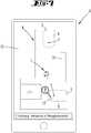
Es wird vorgeschlagen, dass der Nutzer die Position der Basisstation in eine auf einem Display des externen Endgerätes dargestellte Umgebungskarte einträgt. Auf dem externen Endgerät des Nutzers ist eine Applikation installiert, welche die Umgebungskarte anzeigt und einem Nutzer eine Änderung und/oder Ergänzung der Umgebungskarte erlaubt, insbesondere dahingehend, dass der Nutzer die Position der Basisstation über eine Tastatur, beispielsweise in Form von X-, Y-Koordinaten, oder direkt über ein die Umgebungskarte darstellendes Touchscreen, einträgt.It is proposed that the user enters the position of the base station in an environment map displayed on a display of the external terminal. On the external terminal of the user, an application is installed, which displays the map and a user allows a change and / or supplement the map, in particular to the effect that the user, the position of the base station via a keyboard, for example in the form of X, Y Coordinates, or directly via a map representing the map touch screen enters.
Des Weiteren wird vorgeschlagen, dass der Rangierbereich in Bezug auf ein darin vorhandenes Hindernis mittels der Detektionseinrichtung eines Servicegerätes und/oder mittels einer Detektionseinrichtung der Basisstation überwacht wird. Einerseits kann somit die Detektionseinrichtung des Servicegerätes selbst eine Detektion von Hindernissen vornehmen, sowie andererseits auch alternativ oder zusätzlich eine Detektionseinrichtung der Basisstation, welche ebenfalls vorzugsweise eine Bilderfassungseinrichtung ist. Besonders vorteilhaft ist dabei, dass die Detektionseinrichtung der Basisstation unmittelbar und permanent auf den Rangierbereich vor der Basisstation gerichtet werden kann. Die von der Detektionseinrichtung der Basisstation aufgenommenen Detektionsergebnisse können dann dem Servicegerät zur Verfügung gestellt werden. Das Servicegerät kann diese Detektionsergebnisse weiterverarbeiten und insbesondere auch in die Umgebungskarte eintragen bzw. zur Information eines Nutzers über die Anwesenheit eines Hindernisses verwenden.Furthermore, it is proposed that the maneuvering area with respect to an obstacle present therein be monitored by means of the detection device of a service device and / or by means of a detection device of the base station. On the one hand, the detection device of the service device itself can thus detect obstacles, and on the other hand, alternatively or additionally, a detection device of the base station, which is also preferably an image capture device. It is particularly advantageous that the detection device of the base station can be directly and permanently directed to the Rangierbereich in front of the base station. The detection results recorded by the detection device of the base station can then be made available to the service device. The service device can further process these detection results and in particular also enter them into the environment map or use them to inform a user about the presence of an obstacle.
Des Weiteren kann vorgesehen sein, dass der Rangierbereich zeitlich vor einem Startzeitpunkt eines Rangiervorgangs zum Annähern, Wenden und/oder Andocken des Servicegerätes an die Basisstation überwacht wird. Insbesondere kann die Überwachung des Rangierbereiches bei Beenden einer Fortbewegung des Servicegerätes und/oder bei Unterschreiten einer kritischen Schwelle eines Ladezustands eines Akkumulators des Servicegerätes und/oder bei Empfang einer Anweisung von einem Nutzer des Servicegerätes erfolgen. Grundsätzlich kann die Überwachung des Rangierbereiches erfolgen, sobald die Position der Basisstation innerhalb der Umgebung bekannt ist. Das Servicegerät bzw. dessen Detektionseinrichtung oder auch die Detektionseinrichtung der Basisstation kann den Rangierbereich fortlaufend überwachen oder, wie vorgeschlagen, speziell vor dem Starten eines Annäherungs- und/oder Andockvorgangs des Servicegerätes an der Basisstation, so dass frühzeitig eine Konfliktsituation für den Navigationsvorgang des Servicegerätes erkannt werden kann und der Nutzer noch rechtzeitig eingreifen kann, um das Hindernis zu entfernen, bevor das Servicegerät ungewünscht stoppt. Wie vorgeschlagen, ist eine einmalige Überprüfung des Rangierbereiches auf Hindernisse denkbar, die beispielsweise unmittelbar vor einem Andocken stattfinden kann. Die Überprüfung wird dabei ausgelöst durch ein Ende eines Servicebetriebes, beispielsweise das Ende einer Reinigungstätigkeit des Servicegerätes, dem Erreichen einer Schwelle für den Ladezustand des Akkumulators des Servicegerätes, der eine Unterbrechung des Servicebetriebes und ein Aufladen des Akkumulators erfordert und/oder ein manuelles Kommando eines Nutzers, beispielsweise ein Kommando zum Abbruch eines Reinigungsvorgangs des Servicegerätes.Furthermore, it can be provided that the maneuvering area is monitored in time before a start time of a maneuvering operation for approaching, turning over and / or docking the service device to the base station. In particular, the monitoring of the maneuvering area can be carried out at the end of a movement of the service device and / or falls below a critical threshold of a state of charge of a battery of the service device and / or upon receipt of an instruction from a user of the service device. In principle, monitoring of the maneuvering area can take place as soon as the position of the base station within the environment is known. The service device or its detection device or else the detection device of the base station can continuously monitor the maneuvering area or, as proposed, especially before starting an approaching and / or docking operation of the service device at the base station so that a conflict situation for the navigation process of the service device is detected early and the user can intervene in time to remove the obstacle before the service device stops unwanted. As suggested, a one-time check of the Rangierbereiches on obstacles is conceivable that can take place, for example, immediately before docking. The check is triggered by an end of a service operation, such as the end of a cleaning activity of the service device, the achievement a threshold for the state of charge of the accumulator of the service device, which requires an interruption of the service operation and charging of the accumulator and / or a manual command of a user, such as a command to cancel a cleaning process of the service device.
Insbesondere wird vorgeschlagen, dass bei Detektion eines Hindernisses in dem Rangierbereich einer Basisstation ermittelt wird, ob andere Basisstationen in der Umgebung zur Verfügung stehen, an welche das Servicegerät andocken kann. Des Weiteren kann vorgesehen sein, dass bei Detektion eines Hindernisses in dem Rangierbereich der Basisstation eine akustische und/oder optische Information über das Hindernis an einen Nutzer des Servicegerätes übermittelt wird, insbesondere an ein externes Endgerät des Nutzers. Im Falle der Detektion eines Hindernisses können unterschiedliche Verfahrensweisen des Servicegerätes initiiert werden, beispielsweise kann als Reaktion auf eine Konfliktsituation eine Information an den Nutzer des Servicegerätes übermittelt werden, z.B. mittels einer auf einem externen Endgerät installierten Applikation, indem ein Ausschnitt der Umgebungskarte mit der Position eines Hindernisses und/oder ein Bild des Hindernisses, welches von einer Detektionseinrichtung des Servicegerätes oder der Basisstation aufgenommen wurde, angezeigt wird. Des Weiteren kann ein akustisches und/oder optisches Signal an den Nutzer übermittelt werden, mit dem Inhalt, dass das Hindernis aus dem Rangierbereich entfernt werden sollte. Der Hinweis kann beispielsweise schriftlich auf einem Display des externen Endgerätes des Nutzers dargestellt werden, über einen Lautsprecher des externen Endgerätes, der Basisstation oder auch des Servicegerätes ausgegeben werden oder dergleichen. Des Weiteren kann als Reaktion auf eine detektierte Konfliktsituation zunächst gewartet und überprüft werden, ob sich das Hindernis wieder aus dem Rangierbereich entfernt. Dies kann beispielsweise der Fall sein, wenn der Nutzer das Hindernis manuell entfernt oder das Hindernis beispielsweise ein Mensch oder ein Haustier war, welcher beziehungsweise welches sich in dem Rangierbereich der Basisstation aufgehalten hat. Falls letzteres der Fall ist, wird eine erneute Information an den Nutzer ausgegeben, mit dem Inhalt, dass sich die Konfliktsituation aufgelöst hat. Als weitere Möglichkeit kann vorgesehen sein, dass eine Recheneinheit des Servicegerätes, der Basisstation oder auch eines externen Endgerätes überprüft, ob mehrere Basisstationen in der Umgebung des Servicegerätes vorhanden sind, wobei bei der tatsächlichen Anwesenheit mehrerer Basisstationen detektiert werden kann, welche Basisstation dem Servicegerät am nächsten liegt und einen freien Rangierbereich ohne dort vorhandene Hindernisse zur Verfügung stellt, so dass das Servicegerät dort ohne eine Kollision andocken könnte.In particular, it is proposed that upon detection of an obstacle in the Rangierbereich a base station is determined whether other base stations are available in the environment to which the service device can dock. Furthermore, it can be provided that upon detection of an obstacle in the maneuvering area of the base station, acoustic and / or visual information about the obstacle is transmitted to a user of the service device, in particular to an external terminal of the user. In the case of detection of an obstacle, different procedures of the service device can be initiated, for example information can be transmitted to the user of the service device in response to a conflict situation, e.g. by means of an application installed on an external terminal by displaying a section of the surroundings map with the position of an obstacle and / or an image of the obstacle which has been recorded by a detection device of the service device or the base station. Furthermore, an acoustic and / or visual signal can be transmitted to the user, with the content that the obstacle should be removed from the Rangierbereich. The note can be displayed for example in writing on a display of the external terminal of the user, are output via a speaker of the external terminal, the base station or the service device or the like. Furthermore, in response to a detected conflict situation, it can first be serviced and checked as to whether the obstacle is moving away from the maneuvering area again. This may be the case, for example, if the user manually removed the obstacle or the obstacle was, for example, a human or a pet, which was in the maneuvering area of the base station. If the latter is the case, a new information is issued to the user, with the content that the conflict situation has resolved. As a further possibility can be provided that a computing unit of the service device, the base station or an external terminal checks if multiple base stations are present in the environment of the service device, which can be detected in the actual presence of multiple base stations, which base station closest to the service device and provides a free maneuvering area without there existing obstacles available so that the service unit could dock there without a collision.
Schließlich wird vorgeschlagen, dass anhand der Umgebungskarte und darin gespeicherter Hindernisse eine optimale räumliche Position für eine Basisstation ermittelt wird, wobei eine Information über die optimale räumliche Position an einen Nutzer des Servicegerätes übermittelt wird. Durch die Analyse historischer Umgebungskarten sowie gespeicherter Konfliktsituationen innerhalb unterschiedlicher Bereiche der Umgebung können einem Nutzer Empfehlungen für einen geeigneten Aufstellort der Basisstation gegeben werden. Dazu können beispielsweise die Kartendaten mehrerer aufeinanderfolgender Serviceläufe, beispielsweise Reinigungsfahrten, des Servicegerätes analysiert werden, dahingehend, ob an ähnlichen Stellen des Raumes ebenfalls Kollisionen mit Hindernissen auftreten bzw. aufgetreten sind. Die Mitteilung über die optimale räumliche Position kann einem Nutzer beispielsweise durch das Servicegerät selbst, durch eine Basisstation oder auch ein externes Endgerät des Nutzers übermittelt werden.Finally, it is proposed that an optimal spatial position for a base station is determined on the basis of the environment map and obstacles stored therein, wherein information about the optimal spatial position is transmitted to a user of the service device. By analyzing historical maps of the surroundings as well as stored conflict situations within different areas of the environment, a user can be given recommendations for a suitable installation location of the base station. For this purpose, for example, the map data of several successive service runs, for example cleaning trips, of the service device can be analyzed as to whether similar areas of the room also encounter collisions with obstacles or have occurred. The message about the optimal spatial position can be transmitted to a user, for example, by the service device itself, by a base station or also by an external terminal of the user.
Insgesamt erhält der Nutzer durch die Erfindung eine frühzeitige Information über eine mögliche Kollision mit Hindernissen beim Andockvorgang an eine Basisstation. Bei fortlaufender Überwachung der Rangierbereiche einer oder mehrerer Basisstationen kann der Nutzer frühzeitig eingreifen, wodurch eine vollständige Entladung eines Akkumulators verhindert wird und ein Betrieb nach dem Andocken und Aufladen an der Basisstation ohne weiteres Eingreifen des Nutzers fortgesetzt werden kann.Overall, the user receives by the invention early information about a possible collision with obstacles during docking to a base station. Continuously monitoring the maneuvering ranges of one or more base stations allows the user to intervene at an early stage, thereby preventing a complete discharge of an accumulator and continuing operation after docking and recharging at the base station without further user intervention.
Figurenlistelist of figures
Im Folgenden wird die Erfindung anhand von Ausführungsbeispielen näher erläutert. Es zeigen:
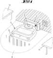
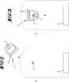
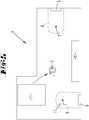
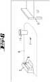
1 eine Umgebung mit einem an einer Basisstation angedockten Servicegerät,2 einen Rangierbereich der Basisstation mit einem Servicegerät vor Befahren des Rangierbereiches,3 dieSituation gemäß 2 während des Wendens des Servicegerätes innerhalb des Rangierbereiches,4 dieSituation gemäß den 2 und3 bei einem angedockten Zustand des Servicegerätes an der Basisstation,5 eine Umgebungskarte der Umgebung,6 einen Teilbereich der Umgebung mit einem in dem Rangierbereich der Basisstation befindlichen Hindernis,7 ein externes Endgerät, auf welchem eine Umgebungskarte dargestellt ist,8 eine Umgebung mit einem Servicegerät und einer Basisstation gemäß einer zweiten Ausführungsform.
1 an environment with a service device docked to a base station,2 a maneuvering area of the base station with a service device before entering the maneuvering area,3 the situation according to2 while turning the service device within the maneuvering area,4 the situation according to the2 and3 in a docked state of the service device at the base station,5 an environment map of the surroundings,6 a partial area of the environment with an obstacle located in the maneuvering area of the base station,7 an external terminal on which an environment map is displayed,8th an environment with a service device and a base station according to a second embodiment.
Beschreibung der AusführungsformenDescription of the embodiments
Das Servicegerät
Mit Hilfe der Detektionseinrichtung
Vor der Basisstation
Wie in
Die
Die Detektionseinrichtung
Alternativ zu einer kontinuierlichen Überwachung der Rangierbereiche
Des Weiteren kann es vorgesehen sein, dass einem Nutzer eine vorteilhafte räumliche Position zum Aufstellen einer Basisstation
BezugszeichenlisteLIST OF REFERENCE NUMBERS
- 11
- Servicegerätservice equipment
- 22
- Detektionseinrichtungdetection device
- 33
- Detektionseinrichtungdetection device
- 44
- Umgebungskartemap
- 55
- Basisstationbase station
- 66
- Rangierbereichshunting
- 77
- Wendepunktturning point
- 88th
- Codecode
- 99
- Externes EndgerätExternal terminal
- 1010
- Displaydisplay
- 1111
- Hindernisobstacle
- 1212
- Reinigungselementcleaning element
ZITATE ENTHALTEN IN DER BESCHREIBUNG QUOTES INCLUDE IN THE DESCRIPTION
Diese Liste der vom Anmelder aufgeführten Dokumente wurde automatisiert erzeugt und ist ausschließlich zur besseren Information des Lesers aufgenommen. Die Liste ist nicht Bestandteil der deutschen Patent- bzw. Gebrauchsmusteranmeldung. Das DPMA übernimmt keinerlei Haftung für etwaige Fehler oder Auslassungen.This list of the documents listed by the applicant has been generated automatically and is included solely for the better information of the reader. The list is not part of the German patent or utility model application. The DPMA assumes no liability for any errors or omissions.
Zitierte PatentliteraturCited patent literature
- DE 102011000536 A1 [0003]DE 102011000536 A1 [0003]
- DE 102008014912 A1 [0003]DE 102008014912 A1 [0003]
Claims (10)
Translated fromGermanPriority Applications (6)
| Application Number | Priority Date | Filing Date | Title |
|---|---|---|---|
| EP18181667.9AEP3428759B1 (en) | 2017-07-13 | 2018-07-04 | Method for operating an automatically moving service device |
| ES18181667TES2829200T3 (en) | 2017-07-13 | 2018-07-04 | Method of operating an automatically moving utility appliance |
| JP2018130392AJP2019021307A (en) | 2017-07-13 | 2018-07-10 | Operation method for autonomously travelling service device |
| US16/033,340US11269348B2 (en) | 2017-07-13 | 2018-07-12 | Method for operating an automatically moving service device |
| TW107124121ATW201908901A (en) | 2017-07-13 | 2018-07-12 | Method of operating a self-propelled service device |
| CN201810768263.5ACN109254580B (en) | 2017-07-13 | 2018-07-13 | Method for operating a self-propelled service device |
Applications Claiming Priority (2)
| Application Number | Priority Date | Filing Date | Title |
|---|---|---|---|
| DE102017006621.3 | 2017-07-13 | ||
| DE102017006621 | 2017-07-13 |
Publications (1)
| Publication Number | Publication Date |
|---|---|
| DE102018116065A1true DE102018116065A1 (en) | 2019-01-17 |
Family
ID=64745174
Family Applications (1)
| Application Number | Title | Priority Date | Filing Date |
|---|---|---|---|
| DE102018116065.8AWithdrawnDE102018116065A1 (en) | 2017-07-13 | 2018-07-03 | Method for operating a self-propelled service device |
Country Status (6)
| Country | Link |
|---|---|
| US (1) | US11269348B2 (en) |
| JP (1) | JP2019021307A (en) |
| CN (1) | CN109254580B (en) |
| DE (1) | DE102018116065A1 (en) |
| ES (1) | ES2829200T3 (en) |
| TW (1) | TW201908901A (en) |
Cited By (1)
| Publication number | Priority date | Publication date | Assignee | Title |
|---|---|---|---|---|
| DE102020212999A1 (en) | 2020-10-15 | 2022-04-21 | BSH Hausgeräte GmbH | Method of operating a mobile, self-propelled device |
Families Citing this family (7)
| Publication number | Priority date | Publication date | Assignee | Title |
|---|---|---|---|---|
| CN108852174B (en)* | 2017-09-25 | 2022-02-25 | 北京石头创新科技有限公司 | Autonomous mobile robot and pile searching method, control device and intelligent cleaning system thereof |
| CN111090284B (en)* | 2019-12-23 | 2024-01-16 | 南京苏美达智能技术有限公司 | Method for returning self-walking equipment to base station and self-walking equipment |
| CN111240322B (en)* | 2020-01-09 | 2020-12-29 | 珠海市一微半导体有限公司 | Determination method and motion control method of working starting point of robot movement limit frame |
| US11662737B2 (en)* | 2020-12-28 | 2023-05-30 | Irobot Corporation | Systems and methods for dock placement for an autonomous mobile robot |
| USD989426S1 (en) | 2021-01-20 | 2023-06-13 | Vorwerk & Co. Interholding Gmbh | Robot vacuum cleaner |
| KR102559299B1 (en)* | 2022-08-29 | 2023-07-25 | 주식회사 클로봇 | Unmanned moving object, method and program for controlling docking of unmanned moving object using marker |
| KR102585353B1 (en)* | 2022-11-10 | 2023-10-06 | 주식회사 클로봇 | Unmanned moving object, method and program for controlling docking of unmanned moving object using ridar and v-shaped marker |
Citations (2)
| Publication number | Priority date | Publication date | Assignee | Title |
|---|---|---|---|---|
| DE102008014912A1 (en) | 2008-03-19 | 2009-09-24 | Vorwerk & Co. Interholding Gmbh | Automatically movable floor dust collecting device and object with a sensor arrangement |
| DE102011000536A1 (en) | 2011-02-07 | 2012-08-09 | Vorwerk & Co. Interholding Gmbh | Method for determining position of e.g. automatically movable household suction robot utilized for cleaning floor of home, involves determining actual position of corresponding sub region of map display by self-localization process |
Family Cites Families (31)
| Publication number | Priority date | Publication date | Assignee | Title |
|---|---|---|---|---|
| JP2679346B2 (en)* | 1990-03-28 | 1997-11-19 | 神鋼電機株式会社 | Charging control method for mobile robot system |
| JP4129442B2 (en)* | 2004-03-24 | 2008-08-06 | 株式会社東芝 | Mobile equipment system |
| US7706917B1 (en) | 2004-07-07 | 2010-04-27 | Irobot Corporation | Celestial navigation system for an autonomous robot |
| WO2006065563A2 (en) | 2004-12-14 | 2006-06-22 | Sky-Trax Incorporated | Method and apparatus for determining position and rotational orientation of an object |
| KR100624387B1 (en) | 2005-04-25 | 2006-09-20 | 엘지전자 주식회사 | Robot system with driving range |
| EP2050544B1 (en) | 2005-09-30 | 2011-08-31 | iRobot Corporation | Robot system with wireless communication by TCP/IP transmissions |
| US9144360B2 (en) | 2005-12-02 | 2015-09-29 | Irobot Corporation | Autonomous coverage robot navigation system |
| US8874261B2 (en) | 2007-07-25 | 2014-10-28 | Deere & Company | Method and system for controlling a mobile robot |
| US20140257845A9 (en) | 2008-08-05 | 2014-09-11 | Vasu Rangadass | Operating System |
| DE102009041362A1 (en)* | 2009-09-11 | 2011-03-24 | Vorwerk & Co. Interholding Gmbh | Method for operating a cleaning robot |
| KR20120049533A (en) | 2010-11-09 | 2012-05-17 | 삼성전자주식회사 | Robot system and method for controlling the same |
| US9069356B2 (en)* | 2011-06-12 | 2015-06-30 | Microsoft Technology Licensing, Llc | Nomadic security device with patrol alerts |
| US8918208B1 (en) | 2012-02-07 | 2014-12-23 | Ryan Hickman | Projection of interactive map data |
| DE102012014939A1 (en)* | 2012-07-27 | 2014-01-30 | Volkswagen Aktiengesellschaft | Method and device for collision avoidance |
| DE102012109004A1 (en)* | 2012-09-24 | 2014-03-27 | RobArt GmbH | Robots and methods for autonomous inspection or processing of floor surfaces |
| US9538892B2 (en)* | 2012-10-05 | 2017-01-10 | Irobot Corporation | Robot management systems for determining docking station pose including mobile robots and methods using same |
| US20140222271A1 (en)* | 2013-02-07 | 2014-08-07 | MetraLabs Automation, Inc. | Autonomous mobile robot inductive charging system |
| KR102061511B1 (en)* | 2013-04-26 | 2020-01-02 | 삼성전자주식회사 | Cleaning robot, home monitoring apparatus and method for controlling the same |
| US9233468B2 (en) | 2013-11-12 | 2016-01-12 | Irobot Corporation | Commanding a mobile robot using glyphs |
| CN103645733B (en)* | 2013-12-02 | 2014-08-13 | 江苏建威电子科技有限公司 | A robot automatically finding a charging station and a system and method for automatically finding a charging station thereof |
| KR20160127013A (en)* | 2014-02-25 | 2016-11-02 | 알프레드 캐르혀 게엠베하 운트 컴파니. 카게 | Method for docking a floor treatment device to a base station, and floor treatment system |
| KR102161200B1 (en) | 2014-04-21 | 2020-09-29 | 삼성전자주식회사 | Method for controlling a sleep mode and an electronic device thereof |
| JP6350011B2 (en) | 2014-06-20 | 2018-07-04 | オムロン株式会社 | Robot control system |
| US9656390B2 (en) | 2014-11-10 | 2017-05-23 | Faro Technologies, Inc. | Human-centric robot with noncontact measurement device |
| US10358326B2 (en) | 2015-03-06 | 2019-07-23 | Walmart Apollo, Llc | Shopping facility assistance systems, devices and methods |
| DE102015114883A1 (en) | 2015-09-04 | 2017-03-09 | RobArt GmbH | Identification and localization of a base station of an autonomous mobile robot |
| US9682481B2 (en) | 2015-10-26 | 2017-06-20 | X Development Llc | Communication of information regarding a robot using an optical identifier |
| US10657802B2 (en) | 2015-11-02 | 2020-05-19 | The Johns Hopkins University | Method, device, and computer-readable medium for mobile device management of collaborative industrial robot |
| CN105990876B (en)* | 2015-12-21 | 2019-03-01 | 小米科技有限责任公司 | Charging pile and its identification method, device and automatic cleaning equipment |
| JP6656423B2 (en) | 2016-05-19 | 2020-03-04 | シムビ ロボティクス, インコーポレイテッドSimbe Robotics, Inc. | How to automatically generate waypoints to image shelves in stores |
| US20180299899A1 (en)* | 2017-04-13 | 2018-10-18 | Neato Robotics, Inc. | Localized collection of ambient data |
- 2018
- 2018-07-03DEDE102018116065.8Apatent/DE102018116065A1/ennot_activeWithdrawn
- 2018-07-04ESES18181667Tpatent/ES2829200T3/enactiveActive
- 2018-07-10JPJP2018130392Apatent/JP2019021307A/enactivePending
- 2018-07-12USUS16/033,340patent/US11269348B2/enactiveActive
- 2018-07-12TWTW107124121Apatent/TW201908901A/enunknown
- 2018-07-13CNCN201810768263.5Apatent/CN109254580B/enactiveActive
Patent Citations (2)
| Publication number | Priority date | Publication date | Assignee | Title |
|---|---|---|---|---|
| DE102008014912A1 (en) | 2008-03-19 | 2009-09-24 | Vorwerk & Co. Interholding Gmbh | Automatically movable floor dust collecting device and object with a sensor arrangement |
| DE102011000536A1 (en) | 2011-02-07 | 2012-08-09 | Vorwerk & Co. Interholding Gmbh | Method for determining position of e.g. automatically movable household suction robot utilized for cleaning floor of home, involves determining actual position of corresponding sub region of map display by self-localization process |
Cited By (2)
| Publication number | Priority date | Publication date | Assignee | Title |
|---|---|---|---|---|
| DE102020212999A1 (en) | 2020-10-15 | 2022-04-21 | BSH Hausgeräte GmbH | Method of operating a mobile, self-propelled device |
| EP3984434B1 (en)* | 2020-10-15 | 2023-08-23 | BSH Hausgeräte GmbH | Method for operating a self-propelled mobile device |
Also Published As
| Publication number | Publication date |
|---|---|
| CN109254580A (en) | 2019-01-22 |
| ES2829200T3 (en) | 2021-05-31 |
| JP2019021307A (en) | 2019-02-07 |
| US11269348B2 (en) | 2022-03-08 |
| TW201908901A (en) | 2019-03-01 |
| US20190018424A1 (en) | 2019-01-17 |
| CN109254580B (en) | 2024-03-05 |
Similar Documents
| Publication | Publication Date | Title |
|---|---|---|
| DE102018116065A1 (en) | Method for operating a self-propelled service device | |
| EP3441840B1 (en) | Method for operating a self-propelled cleaning device | |
| EP2837985B1 (en) | Autonomous transport vehicle and method for operating an autonomous transport vehicle | |
| EP3415065B1 (en) | System comprising two cleaning devices | |
| EP3379990B1 (en) | Floor cleaning system and method for cleaning a floor surface | |
| EP3416019B1 (en) | System comprising at least two automatic advancing ground working tools | |
| EP2764812B1 (en) | Cleaning robot | |
| EP3538967B1 (en) | Method and system for operating an automatically moving robot | |
| EP3355147B1 (en) | Method for operating an automatically moving vehicle | |
| EP3559773B1 (en) | Method for the navigation and self-location of an autonomously moving processing device | |
| DE102016221680A1 (en) | Method for operating a semi-autonomous or autonomous motor vehicle and motor vehicle | |
| EP3559770B1 (en) | Method for operating an automatically moving cleaning device and cleaning device of this type | |
| EP3663252A1 (en) | Method for operating an agv and intralogistic system with an agv | |
| EP3453672A1 (en) | Method and device for collision avoidance during the operation of an industrial truck | |
| DE102012112035A1 (en) | Robot vacuum cleaner operating method, involves transferring processing date to vacuum cleaner in operation of robot vacuum cleaner as result of processing control information returns to cleaner for activation of cleaner by individual | |
| EP3378825A1 (en) | Industrial truck with airborne object | |
| EP3805891A1 (en) | Driverless transport vehicle for intralogistics | |
| WO2020074722A1 (en) | Method and robot system for inputting a work area | |
| EP3428759B1 (en) | Method for operating an automatically moving service device | |
| EP3553621A2 (en) | Road sweeper | |
| EP4387499A1 (en) | Floor-cleaning system, floor-cleaning apparatus, and method for operating a floor-cleaning system or a floor-cleaning apparatus | |
| DE102019215435A1 (en) | Method and device for warning a person at risk in the vicinity of an automated vehicle | |
| EP4158436B1 (en) | Method for bypassing impassable obstacles by a robot | |
| EP3254593B1 (en) | Sensor assembly for the optimized navigation of a mobile robbot unit | |
| EP2466410B1 (en) | Method and device for automatically controlling a transport system |
Legal Events
| Date | Code | Title | Description |
|---|---|---|---|
| R119 | Application deemed withdrawn, or ip right lapsed, due to non-payment of renewal fee |