DE102018113466A1 - Rope, in particular for bracing components of a wind energy plant - Google Patents
Rope, in particular for bracing components of a wind energy plantDownload PDFInfo
- Publication number
- DE102018113466A1 DE102018113466A1DE102018113466.5ADE102018113466ADE102018113466A1DE 102018113466 A1DE102018113466 A1DE 102018113466A1DE 102018113466 ADE102018113466 ADE 102018113466ADE 102018113466 A1DE102018113466 A1DE 102018113466A1
- Authority
- DE
- Germany
- Prior art keywords
- rope
- plastic profiles
- cable
- seilendhülse
- end sleeve
- Prior art date
- Legal status (The legal status is an assumption and is not a legal conclusion. Google has not performed a legal analysis and makes no representation as to the accuracy of the status listed.)
- Withdrawn
Links
- 229920002430Fibre-reinforced plasticPolymers0.000claimsabstractdescription5
- 239000011151fibre-reinforced plasticSubstances0.000claimsabstractdescription5
- 239000004033plasticSubstances0.000claimsdescription53
- 229920003023plasticPolymers0.000claimsdescription53
- 239000011347resinSubstances0.000claimsdescription9
- 229920005989resinPolymers0.000claimsdescription9
- 229920000049Carbon (fiber)Polymers0.000claimsdescription5
- 239000004917carbon fiberSubstances0.000claimsdescription5
- 238000009413insulationMethods0.000claimsdescription5
- 239000012212insulatorSubstances0.000claimsdescription3
- VNWKTOKETHGBQD-UHFFFAOYSA-NmethaneChemical compoundCVNWKTOKETHGBQD-UHFFFAOYSA-N0.000description4
- 229910000831SteelInorganic materials0.000description3
- 230000005540biological transmissionEffects0.000description3
- 239000011248coating agentSubstances0.000description3
- 238000000576coating methodMethods0.000description3
- 239000000463materialSubstances0.000description3
- 239000010959steelSubstances0.000description3
- 238000004519manufacturing processMethods0.000description2
- BUHVIAUBTBOHAG-FOYDDCNASA-N(2r,3r,4s,5r)-2-[6-[[2-(3,5-dimethoxyphenyl)-2-(2-methylphenyl)ethyl]amino]purin-9-yl]-5-(hydroxymethyl)oxolane-3,4-diolChemical compoundCOC1=CC(OC)=CC(C(CNC=2C=3N=CN(C=3N=CN=2)[C@H]2[C@@H]([C@H](O)[C@@H](CO)O2)O)C=2C(=CC=CC=2)C)=C1BUHVIAUBTBOHAG-FOYDDCNASA-N0.000description1
- 239000004593EpoxySubstances0.000description1
- 238000005452bendingMethods0.000description1
- 238000010276constructionMethods0.000description1
- 229920003020cross-linked polyethylenePolymers0.000description1
- 239000004703cross-linked polyethyleneSubstances0.000description1
- 238000009795derivationMethods0.000description1
- 238000010292electrical insulationMethods0.000description1
- 230000005284excitationEffects0.000description1
- 239000003000extruded plasticSubstances0.000description1
- 239000000835fiberSubstances0.000description1
- 230000009931harmful effectEffects0.000description1
- 238000002347injectionMethods0.000description1
- 239000007924injectionSubstances0.000description1
- 239000011159matrix materialSubstances0.000description1
- 230000001404mediated effectEffects0.000description1
- 239000002184metalSubstances0.000description1
- 239000012811non-conductive materialSubstances0.000description1
- 230000000149penetrating effectEffects0.000description1
- 229920002635polyurethanePolymers0.000description1
- 239000004814polyurethaneSubstances0.000description1
Images


Classifications
- D—TEXTILES; PAPER
- D07—ROPES; CABLES OTHER THAN ELECTRIC
- D07B—ROPES OR CABLES IN GENERAL
- D07B5/00—Making ropes or cables from special materials or of particular form
- D07B5/10—Making ropes or cables from special materials or of particular form from strands of non-circular cross-section
- D—TEXTILES; PAPER
- D07—ROPES; CABLES OTHER THAN ELECTRIC
- D07B—ROPES OR CABLES IN GENERAL
- D07B1/00—Constructional features of ropes or cables
- D07B1/02—Ropes built-up from fibrous or filamentary material, e.g. of vegetable origin, of animal origin, regenerated cellulose, plastics
- D07B1/04—Ropes built-up from fibrous or filamentary material, e.g. of vegetable origin, of animal origin, regenerated cellulose, plastics with a core of fibres or filaments arranged parallel to the centre line
- F—MECHANICAL ENGINEERING; LIGHTING; HEATING; WEAPONS; BLASTING
- F16—ENGINEERING ELEMENTS AND UNITS; GENERAL MEASURES FOR PRODUCING AND MAINTAINING EFFECTIVE FUNCTIONING OF MACHINES OR INSTALLATIONS; THERMAL INSULATION IN GENERAL
- F16G—BELTS, CABLES, OR ROPES, PREDOMINANTLY USED FOR DRIVING PURPOSES; CHAINS; FITTINGS PREDOMINANTLY USED THEREFOR
- F16G11/00—Means for fastening cables or ropes to one another or to other objects; Caps or sleeves for fixing on cables or ropes
- F16G11/04—Means for fastening cables or ropes to one another or to other objects; Caps or sleeves for fixing on cables or ropes with wedging action, e.g. friction clamps
- F16G11/042—Means for fastening cables or ropes to one another or to other objects; Caps or sleeves for fixing on cables or ropes with wedging action, e.g. friction clamps using solidifying liquid material forming a wedge
- D—TEXTILES; PAPER
- D07—ROPES; CABLES OTHER THAN ELECTRIC
- D07B—ROPES OR CABLES IN GENERAL
- D07B2201/00—Ropes or cables
- D07B2201/20—Rope or cable components
- D07B2201/2015—Strands
- D07B2201/2016—Strands characterised by their cross-sectional shape
- D—TEXTILES; PAPER
- D07—ROPES; CABLES OTHER THAN ELECTRIC
- D07B—ROPES OR CABLES IN GENERAL
- D07B2201/00—Ropes or cables
- D07B2201/20—Rope or cable components
- D07B2201/2015—Strands
- D07B2201/2033—Parallel wires
- D—TEXTILES; PAPER
- D07—ROPES; CABLES OTHER THAN ELECTRIC
- D07B—ROPES OR CABLES IN GENERAL
- D07B2201/00—Ropes or cables
- D07B2201/20—Rope or cable components
- D07B2201/2015—Strands
- D07B2201/2046—Strands comprising fillers
- D—TEXTILES; PAPER
- D07—ROPES; CABLES OTHER THAN ELECTRIC
- D07B—ROPES OR CABLES IN GENERAL
- D07B2201/00—Ropes or cables
- D07B2201/20—Rope or cable components
- D07B2201/2047—Cores
- D07B2201/2052—Cores characterised by their structure
- D07B2201/2055—Cores characterised by their structure comprising filaments or fibers
- D07B2201/2056—Cores characterised by their structure comprising filaments or fibers arranged parallel to the axis
- D—TEXTILES; PAPER
- D07—ROPES; CABLES OTHER THAN ELECTRIC
- D07B—ROPES OR CABLES IN GENERAL
- D07B2201/00—Ropes or cables
- D07B2201/20—Rope or cable components
- D07B2201/2083—Jackets or coverings
- D07B2201/2087—Jackets or coverings being of the coated type
- D—TEXTILES; PAPER
- D07—ROPES; CABLES OTHER THAN ELECTRIC
- D07B—ROPES OR CABLES IN GENERAL
- D07B2205/00—Rope or cable materials
- D07B2205/20—Organic high polymers
- D07B2205/201—Polyolefins
- D—TEXTILES; PAPER
- D07—ROPES; CABLES OTHER THAN ELECTRIC
- D07B—ROPES OR CABLES IN GENERAL
- D07B2205/00—Rope or cable materials
- D07B2205/20—Organic high polymers
- D07B2205/206—Epoxy resins
- D—TEXTILES; PAPER
- D07—ROPES; CABLES OTHER THAN ELECTRIC
- D07B—ROPES OR CABLES IN GENERAL
- D07B2205/00—Rope or cable materials
- D07B2205/20—Organic high polymers
- D07B2205/2064—Polyurethane resins
- D—TEXTILES; PAPER
- D07—ROPES; CABLES OTHER THAN ELECTRIC
- D07B—ROPES OR CABLES IN GENERAL
- D07B2205/00—Rope or cable materials
- D07B2205/30—Inorganic materials
- D07B2205/3007—Carbon
- D—TEXTILES; PAPER
- D07—ROPES; CABLES OTHER THAN ELECTRIC
- D07B—ROPES OR CABLES IN GENERAL
- D07B5/00—Making ropes or cables from special materials or of particular form
- D07B5/002—Making parallel wire strands
- F—MECHANICAL ENGINEERING; LIGHTING; HEATING; WEAPONS; BLASTING
- F03—MACHINES OR ENGINES FOR LIQUIDS; WIND, SPRING, OR WEIGHT MOTORS; PRODUCING MECHANICAL POWER OR A REACTIVE PROPULSIVE THRUST, NOT OTHERWISE PROVIDED FOR
- F03D—WIND MOTORS
- F03D13/00—Assembly, mounting or commissioning of wind motors; Arrangements specially adapted for transporting wind motor components
- F03D13/20—Arrangements for mounting or supporting wind motors; Masts or towers for wind motors
- F03D13/25—Arrangements for mounting or supporting wind motors; Masts or towers for wind motors specially adapted for offshore installation
- F—MECHANICAL ENGINEERING; LIGHTING; HEATING; WEAPONS; BLASTING
- F05—INDEXING SCHEMES RELATING TO ENGINES OR PUMPS IN VARIOUS SUBCLASSES OF CLASSES F01-F04
- F05B—INDEXING SCHEME RELATING TO WIND, SPRING, WEIGHT, INERTIA OR LIKE MOTORS, TO MACHINES OR ENGINES FOR LIQUIDS COVERED BY SUBCLASSES F03B, F03D AND F03G
- F05B2240/00—Components
- F05B2240/90—Mounting on supporting structures or systems
- F05B2240/91—Mounting on supporting structures or systems on a stationary structure
- F05B2240/917—Mounting on supporting structures or systems on a stationary structure attached to cables
- Y—GENERAL TAGGING OF NEW TECHNOLOGICAL DEVELOPMENTS; GENERAL TAGGING OF CROSS-SECTIONAL TECHNOLOGIES SPANNING OVER SEVERAL SECTIONS OF THE IPC; TECHNICAL SUBJECTS COVERED BY FORMER USPC CROSS-REFERENCE ART COLLECTIONS [XRACs] AND DIGESTS
- Y02—TECHNOLOGIES OR APPLICATIONS FOR MITIGATION OR ADAPTATION AGAINST CLIMATE CHANGE
- Y02E—REDUCTION OF GREENHOUSE GAS [GHG] EMISSIONS, RELATED TO ENERGY GENERATION, TRANSMISSION OR DISTRIBUTION
- Y02E10/00—Energy generation through renewable energy sources
- Y02E10/70—Wind energy
- Y02E10/72—Wind turbines with rotation axis in wind direction
Landscapes
- Engineering & Computer Science (AREA)
- General Engineering & Computer Science (AREA)
- Mechanical Engineering (AREA)
- Wind Motors (AREA)
- Ropes Or Cables (AREA)
Abstract
Translated fromGermanDescription
Translated fromGermanDie Erfindung betrifft ein Seil. Insbesondere betrifft die Erfindung ein Seil zur Abspannung von Komponenten einer Windenergieanlage. Speziell betrifft die Erfindung ein Seil zur Abspannung des Turms einer Windenergieanlage und eine dieses Seil aufweisende Windenergieanlage.The invention relates to a rope. In particular, the invention relates to a rope for bracing components of a wind turbine. Specifically, the invention relates to a rope for bracing the tower of a wind turbine and a wind turbine having this rope.
Seile zur Abspannung von Bauwerken, insbesondere von Masten aufweisenden Windenergieanlagen sind aus offenkundiger Vorbenutzung hinreichend bekannt. Derartige als Stahlseile ausgebildete Seile bestehen aus zusammengedrehten Drähten, die insbesondere zur Übertragung von im Bereich der Gondel auftretenden Lasten und deren Ableitung in das Fundament der Windenergieanlage verwendet werden.Ropes for bracing of structures, in particular masts having wind turbines are well known from public prior use. Such trained as steel ropes ropes consist of twisted wires, which are used in particular for the transmission of loads occurring in the region of the nacelle and their derivation into the foundation of the wind turbine.
Zur Übertragung großer Lasten werden Paralleldrahtseile verwendet, die aus parallel nebeneinander liegenden, also nicht verdrehten oder geschlagenen Drähten hergestellt sind und eine gleichmäßige Beanspruchung der Seildrähte und eine über den Querschnitt des Drahtseils gleichmäßig verteilte Lastübertragung ermöglichen. Derartige Paralleldrahtseile sind jedoch sehr aufwändig, zumeist nur direkt am Ort der Verwendung herzustellen und eignen sich nicht zur Verwendung in einer Vielzahl von Anwendungen.To transfer large loads parallel wire ropes are used, which are made of parallel juxtaposed, so not twisted or beaten wires and allow uniform loading of the cable wires and over the cross section of the wire evenly distributed load transfer. However, such parallel wire ropes are very expensive, usually only to produce directly at the place of use and are not suitable for use in a variety of applications.
Darüber hinaus sind Drahtseile allgemein sehr schwer. Aufgrund Ihres Gewichts haben sie eine niedrige Biegeeigenfrequenz und neigen bei entsprechender Anregung zu Schwingungen, die bei Windenergieanlagen zu schädlichen Auswirkungen führen. Es ist daher erforderlich, die Eigenfrequenz von Abspannseilen zu erhöhen, damit keine Anregung mehr stattfinden kann. Dafür muss das Verhältnis von Elastizitätsmodul des Abspannseils zu dessen spezifischer Masse maximiert werden.In addition, wire ropes are generally very heavy. Due to their weight, they have a low natural bending frequency and, if excited, tend to produce vibrations that cause harmful effects in wind turbines. It is therefore necessary to increase the natural frequency of guy ropes, so that no excitation can take place. For this, the ratio of modulus of elasticity of the guy rope to its specific mass must be maximized.
Aufgabe der Erfindung ist es daher, ein Seil zu schaffen, das eine über den Querschnitt verteilte gleichmäßige Lasteinleitung und -übertragung ermöglicht und verhältnismäßig einfach für eine Vielzahl von Anwendungen herzustellen ist.The object of the invention is therefore to provide a rope that allows distributed over the cross-section uniform load application and transmission and is relatively easy to produce for a variety of applications.
Diese Aufgabe wird erfindungsgemäß durch das Seil mit den Merkmalen von Anspruch 1 gelöst. Die Unteransprüche geben vorteilhafte Ausgestaltungen der Erfindung wieder.This object is achieved by the rope with the features of claim 1. The subclaims reflect advantageous embodiments of the invention.
Grundgedanke der Erfindung ist es, ein Seil aus einer Mehrzahl von parallel angeordneten pultrudierten Kunststoffprofilen, also stranggezogenen Kunststoffprofilen herzustellen. Das Bereitstellen von Kunststoffprofilen, die bevorzugt jeweils eine identische Querschnittsfläche aufweisen, ermöglicht ein industrielles Herstellungsverfahren für ein Seil, das die Vorteile eines Paralleldrahtseils mit einem einfachen Herstellungsverfahren und einem gegenüber der Verwendung von Stahldraht geringerem Gewicht vereint.The basic idea of the invention is to produce a rope from a plurality of pultruded plastic profiles arranged in parallel, ie extruded plastic profiles. The provision of plastic profiles, which preferably each have an identical cross-sectional area, enables an industrial manufacturing process for a rope that combines the advantages of a parallel wire rope with a simple manufacturing process and a lighter weight compared to the use of steel wire.
Insbesondere geht es bei der vorliegenden Erfindung vor allem darum, die bei der Verwendung an Windenergieanlagen auftretende Eigenfrequenz des Seils zu erhöhen die Seilstruktur so auszulegen, dass hohe Lasten in die Übertragungsstruktur eingeleitet werden können. Dieses wird insbesondere durch die Verwendung von einzelnen im Querschnitt kleinen Einzelprofilen erreicht, die zu einem Seil zusammengesetzt sind. So ist das Verhältnis aus Elastizitätsmodul zu spezifischem Streckengewicht bei der Verwendung von Kohlefaserseilen aus stranggezogenen Unidirektionalfasern bei im Verhältnis zu Stahlseilen gleicher Festigkeit um einen Faktor von ca. 5 höher.In particular, in the present invention, it is above all a matter of increasing the natural frequency of the rope occurring when used on wind energy plants, designing the cable structure such that high loads can be introduced into the transmission structure. This is achieved in particular by the use of individual cross-section small individual profiles, which are assembled into a rope. Thus, the ratio of elastic modulus to specific line weight when using carbon fiber ropes of pultruded unidirectional fibers is higher by a factor of about 5 relative to steel ropes of the same strength.
Erfindungsgemäß ist also ein Seil vorgesehen, das ein Bündel aus pultrudierten faserverstärkten Kunststoffprofilen aufweist. Insbesondere weist das Seil ein Bündel von parallel angeordneten, pultrudierten faserverstärkten Kunststoffprofilen auf.According to the invention, therefore, a rope is provided which has a bundle of pultruded fiber-reinforced plastic profiles. In particular, the rope has a bundle of parallel, pultruded fiber-reinforced plastic profiles.
Die Kunststoffprofile sind bevorzugt aus einem in einer Epoxidmatrix eingebetteten Kohlefaserwerkstoff gebildet.The plastic profiles are preferably formed from a carbon fiber material embedded in an epoxy matrix.
Die Kunststoffprofile sind bevorzugt derart ausgebildet und angeordnet, dass das Bündel im Querschnitt als Kern mit einer Mehrzahl von sektorförmig ausgebildeten Kunststoffprofilen ausgebildet ist, der von wenigstens einem Kreisring mit einer Mehrzahl von kreisringsektorförmig ausgebildeten Kunststoffprofilen umgeben ist.The plastic profiles are preferably formed and arranged such that the bundle is formed in cross-section as a core with a plurality of sector-shaped plastic profiles, which is surrounded by at least one circular ring with a plurality of circular sector shaped plastic profiles.
Insbesondere weisen der Kern und der wenigstens eine Kreisring jeweils eine geradzahlige Anzahl von Kunststoffprofilen auf.In particular, the core and the at least one circular ring each have an even number of plastic profiles.
Dabei sind besonders bevorzugt die Stoßkanten von in einem Kreisring benachbart angeordneten kreisringsektorförmig ausgebildeten Kunststoffprofilen zwischen den Stoßkanten von Kunststoffprofilen des benachbarten Kerns und/oder eines weiteren Kreisrings angeordnet. Insbesondere unterscheidet sich die Anzahl der zu einem Ring zusammengesetzten Kunststoffprofile zwischen benachbarten Ringen. Speziell ist die Anzahl der zu einem Ring zusammengesetzten Kunststoffprofile eine Primzahl.In this case, particularly preferably the abutting edges of adjacent in a circular ring arranged circular sector shaped plastic profiles between the abutting edges of plastic profiles of the adjacent core and / or a further circular ring are arranged. In particular, the number of plastic profiles assembled into a ring differs between adjacent rings. Specifically, the number of plastic profiles assembled into a ring is a prime number.
Weisen die Kunststoffprofile nicht ohnehin bereits eine Oberfläche mit einer vorbestimmten Rauigkeit auf, ist weiter bevorzugt vorgesehen, dass die Oberflächen der Kunststoffprofile geschliffen sind und eine vorbestimmte Rauheit aufweisen.If the plastic profiles do not already have a surface with a predetermined roughness, it is further preferred that the surfaces of the plastic profiles are ground and have a predetermined roughness.
Das Bündel von Kunststoffprofilen ist bevorzugt von einem UV-beständigen und/oder wetterbeständigen und/oder elektrisch isolierenden Isolator umgeben. Dieser Isolator kann beispielsweise eine die Kunststoffprofile umgebende Beschichtung, insbesondere eine Beschichtung mit Polyurethan oder eine Beschichtung mit einem vernetzten Polyethylen (VPE) sein. The bundle of plastic profiles is preferably surrounded by a UV-resistant and / or weather-resistant and / or electrically insulating insulator. This insulator may for example be a coating surrounding the plastic profiles, in particular a coating with polyurethane or a coating with a cross-linked polyethylene (VPE).
Nach einer weiteren bevorzugten Ausgestaltung ist eine mit dem Seil verbundene, konisch ausgebildete Seilendhülse mit einem an der Basis angeordneten Anschlagpunkt vorgesehen, sodass das Seil problemlos an entsprechenden Verbindungsmitteln angeschlagen werden kann.According to a further preferred embodiment, a connected to the rope, conically shaped Seilendhülse is provided with an arranged on the base attachment point, so that the rope can be easily struck at corresponding connection means.
Insbesondere weist der Anschlagpunkt ein mit einem an der Seilendhülse angeordneten Gewinde schraubendes Gewinde auf.In particular, the attachment point has a screw thread with a thread arranged on the cable end sleeve.
Eine vorteilhafte Weiterbildung der Erfindung besteht darin, dass in der Seilendhülse eine die Kunststoffprofile radial auseinanderzwängende Stachelplatte vorgesehen ist, die bevorzugt aus einem elektrisch nicht-leitfähigem Material gebildet ist. Die Stachelplatte hält die einzelnen Kunststoffprofile in einem gleichmäßigen Abstand zueinander. Dieses dient dazu, eine optimale Verklebung der Profile untereinander und mit der Metallhülse zu erreichen.An advantageous development of the invention is that in the Seilendhülse a plastic profiles radially auseinanderzwängende barb plate is provided, which is preferably formed from an electrically non-conductive material. The barb plate holds the individual plastic profiles at a uniform distance from each other. This serves to achieve an optimal bonding of the profiles with each other and with the metal sleeve.
Insbesondere ist ein von der Seilendhülse aufgenommener und von der Stachelplatte verschlossener, die Enden der Kunststoffprofile aufnehmender kegelförmiger Hülseneinsatz mit wenigstens einer dessen Mantel durchstoßenden Öffnung vorgesehen.In particular, a cone-shaped sleeve insert, which is accommodated by the cable end sleeve and closed by the barbed plate, which receives the ends of the plastic profiles, is provided with at least one opening piercing its jacket.
Alternativ zu einer Stachelplatte kann auch eine Lochplatte verwendet werden, die eine Mehrzahl von Löchern aufweist, die bevorzugt jeweils ein Kunststoffprofil aufnehmen. Auch durch diese Ausgestaltung kann eine Spreizung der Kunststoffprofile im Bereich der Seilendhülse erreicht werden.As an alternative to a barbed plate, it is also possible to use a perforated plate which has a plurality of holes which preferably each receive a plastic profile. Also by this configuration, a spreading of the plastic profiles in the region of the cable end sleeve can be achieved.
Weiter ist in die Seilendhülse ein die Kunststoffprofile im Bereich der Seilendhülse auseinanderzwängendes und stoffschlüssig miteinander verbindendes Harz eingebracht. Das Harz wird besonders bevorzugt durch die den Mantel des Hülseneinsatzes durchstoßenden Öffnungen zwischen die durch die Stachelplatte gespreizten Kunststoffprofile gebracht.Further, a plastic profile in the region of the cable end sleeve auseinanderzwängendes and cohesively interconnecting resin is introduced into the Seilendhülse. The resin is particularly preferably brought through the openings penetrating the jacket of the sleeve insert between the plastic profiles spread through the barbed plate.
Schließlich ist eine die Seilendhülse auskleidende, die Seilendhülse gegenüber den Kunststoffprofilen elektrisch isolierende Isolierung vorgesehen. Die Isolierung ist insbesondere dann notwendig, wenn die Kunststoffprofile einen elektrisch leitfähigen Kohlefaserwerkstoff aufweisen, um eine Blitzstromableitung über das Seil zu verhindern.Finally, the cable end sleeve lining, the cable end sleeve opposite the plastic profiles electrically insulating insulation is provided. The insulation is particularly necessary if the plastic profiles have an electrically conductive carbon fiber material to prevent lightning current through the cable.
Die Erfindung wird im Folgenden anhand eines in den beigefügten Zeichnungen dargestellten, besonders bevorzugt ausgestalteten Ausführungsbeispiels näher erläutert. Es zeigen:
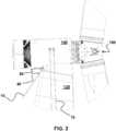
1 eine Seitenansicht einer bevorzugt ausgestalteten schwimmenden Windenergieanlage mit einem mittels gemäß der Erfindung besonders bevorzugt ausgestalteter Seile abgespannten Turm;2 eine Detailansicht der Windenergieanlage aus1 im Bereich der Gondel der Windenergieanlage;3 eine Explosionsansicht eines besonders bevorzugt ausgestalteten Seils;4 Detailansichten (A ,B ) des im Hülseneinsatz angeordneten Seils;5 Frontalansichten des im Hülseneinsatz angeordneten Seils (A ) und Querschnitte des Seils (B ,C ) nach bevorzugten Ausgestaltungen der Erfindung;6 eine Detailansicht eines besonders bevorzugt ausgestalteten Seils im Bereich der Endhülse als Längsschnitt (A ), in Draufsicht (B ) und als Frontalansicht (C ); und7 eine Draufsicht auf zwei bevorzugt ausgestaltete Ausführungsbeispiele einer anstelle der Stachelplatte zu verwendenden Lochplatte zum Auseinanderzwängen der Kunststoffprofile im Bereich der Seilendhülse.
1 a side view of a preferably designed floating wind turbine with a tautened by means of the invention particularly preferred designed ropes tower;2 a detailed view of the wind turbine1 in the area of the nacelle of the wind turbine;3 an exploded view of a particularly preferred designed rope;4 Detailed views (A .B ) of the cable arranged in the sleeve insert;5 Frontal views of the arranged in the sleeve insert rope (A ) and cross sections of the rope (B .C ) according to preferred embodiments of the invention;6 a detailed view of a particularly preferred designed rope in the end sleeve as a longitudinal section (A ), in plan view (B ) and as a frontal view (C ); and7 a plan view of two preferably configured embodiments of a instead of the barb plate to be used perforated plate for squeezing the plastic profiles in the region of the cable end sleeve.
Der Aufbau der in
Der Mast
Zur Befestigung der Seile
Der Aufbau eines besonders bevorzugt ausgestalteten Seils ist in
Das Seil
Das Ende des Bündels ist innerhalb einer Seilendhülse
Anstelle der Stachelplatte
Schließlich wird die Seilendhülse
Die Profile
Schließlich zeigt
Wie zuvor beschrieben ist das Ende des Seils
Das Harz füllt somit den freien Raum der Seilendhülse
Die Seilendhülse
ZITATE ENTHALTEN IN DER BESCHREIBUNG QUOTES INCLUDE IN THE DESCRIPTION
Diese Liste der vom Anmelder aufgeführten Dokumente wurde automatisiert erzeugt und ist ausschließlich zur besseren Information des Lesers aufgenommen. Die Liste ist nicht Bestandteil der deutschen Patent- bzw. Gebrauchsmusteranmeldung. Das DPMA übernimmt keinerlei Haftung für etwaige Fehler oder Auslassungen.This list of the documents listed by the applicant has been generated automatically and is included solely for the better information of the reader. The list is not part of the German patent or utility model application. The DPMA assumes no liability for any errors or omissions.
Zitierte PatentliteraturCited patent literature
- EP 3019740 B1 [0025]EP 3019740 B1 [0025]
Claims (14)
Translated fromGermanPriority Applications (4)
| Application Number | Priority Date | Filing Date | Title |
|---|---|---|---|
| DE102018113466.5ADE102018113466A1 (en) | 2018-06-06 | 2018-06-06 | Rope, in particular for bracing components of a wind energy plant |
| PCT/IB2019/000456WO2019234491A1 (en) | 2018-06-06 | 2019-05-29 | Cable, in particular cable stay for components of a wind turbine |
| CN201980037913.1ACN112236556B (en) | 2018-06-06 | 2019-05-29 | Cable, in particular for tensioning a component of a wind turbine |
| EP19732441.1AEP3775366B1 (en) | 2018-06-06 | 2019-05-29 | Cable, in particular cable stay for components of a wind turbine |
Applications Claiming Priority (1)
| Application Number | Priority Date | Filing Date | Title |
|---|---|---|---|
| DE102018113466.5ADE102018113466A1 (en) | 2018-06-06 | 2018-06-06 | Rope, in particular for bracing components of a wind energy plant |
Publications (1)
| Publication Number | Publication Date |
|---|---|
| DE102018113466A1true DE102018113466A1 (en) | 2019-12-12 |
Family
ID=66999861
Family Applications (1)
| Application Number | Title | Priority Date | Filing Date |
|---|---|---|---|
| DE102018113466.5AWithdrawnDE102018113466A1 (en) | 2018-06-06 | 2018-06-06 | Rope, in particular for bracing components of a wind energy plant |
Country Status (4)
| Country | Link |
|---|---|
| EP (1) | EP3775366B1 (en) |
| CN (1) | CN112236556B (en) |
| DE (1) | DE102018113466A1 (en) |
| WO (1) | WO2019234491A1 (en) |
Cited By (1)
| Publication number | Priority date | Publication date | Assignee | Title |
|---|---|---|---|---|
| IT202000009814A1 (en)* | 2020-05-05 | 2021-11-05 | Maxspar S R L | METHOD OF PRODUCTION OF A TERMINAL FOR PRE-TENSIONED SHROUDS IN CARBON FIBER AND PRODUCT THUS OBTAINED |
Citations (5)
| Publication number | Priority date | Publication date | Assignee | Title |
|---|---|---|---|---|
| WO1995029308A1 (en)* | 1994-04-25 | 1995-11-02 | Eidgenössische Materialprüfungs- und Forschungsanstalt Empa | Anchorage device for high-performance fiber composite cables |
| WO2009130525A1 (en)* | 2008-04-24 | 2009-10-29 | Szaplonczay Pal | Process and equipment for producing composite core with thermoplastic matrix for recyclable and thermally stable electrical transmission line conductor |
| WO2012037265A2 (en)* | 2010-09-17 | 2012-03-22 | 3M Innovative Properties Company | Fiber-reinforced nanoparticle-loaded thermoset polymer composite wires and cables, and methods |
| WO2012140048A2 (en)* | 2011-04-11 | 2012-10-18 | Lm Wind Power A/S | Wind turbine blade having a root region with elongated fastening members provided with metal fibres |
| EP3019740B1 (en) | 2014-07-01 | 2017-11-01 | Aerodyn Engineering GmbH | Floating wind turbine with a floating foundation, and method for installation of such a wind turbine |
Family Cites Families (12)
| Publication number | Priority date | Publication date | Assignee | Title |
|---|---|---|---|---|
| US3371476A (en)* | 1965-04-02 | 1968-03-05 | Gen Motors Corp | Glass plastic rope |
| US3911785A (en)* | 1974-01-18 | 1975-10-14 | Wall Ind Inc | Parallel yarn rope |
| SU842114A1 (en)* | 1979-08-15 | 1981-06-30 | Предприятие П/Я В-8662 | Steel cable |
| JPH09132884A (en)* | 1995-11-07 | 1997-05-20 | Mitsubishi Rayon Co Ltd | Fiber reinforced resin strand |
| AUPN843596A0 (en)* | 1996-03-04 | 1996-03-28 | Pacific Dunlop Limited | Cable componentry |
| EP1334943B1 (en)* | 2000-07-27 | 2011-03-09 | Mitsubishi Denki Kabushiki Kaisha | Elevator system |
| CN102139544B (en)* | 2003-10-22 | 2016-12-21 | Ctc电缆公司 | aluminum conductor composite core reinforced cable and preparation method thereof |
| FI125355B (en)* | 2007-04-19 | 2015-09-15 | Kone Corp | Rope for lifting device and method for producing a rope for a lifting device |
| CN201302833Y (en)* | 2008-11-17 | 2009-09-02 | 中国电力科学研究院 | A composite core and a conducting wire |
| CH707004B1 (en)* | 2012-09-17 | 2016-07-29 | Fatzer Ag | Cable and an adapter for a splice of a wire rope. |
| CN103306150B (en)* | 2013-06-07 | 2016-01-20 | 南京诺尔泰复合材料设备制造有限公司 | The high strength composite twisted wire of trapezoid cross section and one-step preppn process thereof |
| ES2609467T3 (en)* | 2013-10-10 | 2017-04-20 | Kone Corporation | Cable for a lifting and lifting device |
- 2018
- 2018-06-06DEDE102018113466.5Apatent/DE102018113466A1/ennot_activeWithdrawn
- 2019
- 2019-05-29WOPCT/IB2019/000456patent/WO2019234491A1/ennot_activeCeased
- 2019-05-29CNCN201980037913.1Apatent/CN112236556B/enactiveActive
- 2019-05-29EPEP19732441.1Apatent/EP3775366B1/enactiveActive
Patent Citations (5)
| Publication number | Priority date | Publication date | Assignee | Title |
|---|---|---|---|---|
| WO1995029308A1 (en)* | 1994-04-25 | 1995-11-02 | Eidgenössische Materialprüfungs- und Forschungsanstalt Empa | Anchorage device for high-performance fiber composite cables |
| WO2009130525A1 (en)* | 2008-04-24 | 2009-10-29 | Szaplonczay Pal | Process and equipment for producing composite core with thermoplastic matrix for recyclable and thermally stable electrical transmission line conductor |
| WO2012037265A2 (en)* | 2010-09-17 | 2012-03-22 | 3M Innovative Properties Company | Fiber-reinforced nanoparticle-loaded thermoset polymer composite wires and cables, and methods |
| WO2012140048A2 (en)* | 2011-04-11 | 2012-10-18 | Lm Wind Power A/S | Wind turbine blade having a root region with elongated fastening members provided with metal fibres |
| EP3019740B1 (en) | 2014-07-01 | 2017-11-01 | Aerodyn Engineering GmbH | Floating wind turbine with a floating foundation, and method for installation of such a wind turbine |
Cited By (1)
| Publication number | Priority date | Publication date | Assignee | Title |
|---|---|---|---|---|
| IT202000009814A1 (en)* | 2020-05-05 | 2021-11-05 | Maxspar S R L | METHOD OF PRODUCTION OF A TERMINAL FOR PRE-TENSIONED SHROUDS IN CARBON FIBER AND PRODUCT THUS OBTAINED |
Also Published As
| Publication number | Publication date |
|---|---|
| WO2019234491A1 (en) | 2019-12-12 |
| EP3775366A1 (en) | 2021-02-17 |
| EP3775366B1 (en) | 2022-08-17 |
| CN112236556A (en) | 2021-01-15 |
| CN112236556B (en) | 2022-09-27 |
Similar Documents
| Publication | Publication Date | Title |
|---|---|---|
| DE102013226536A1 (en) | Arrangement with a concrete foundation and a tower and method for erecting a tower | |
| EP3092358B2 (en) | Wind turbine comprising a segmented tower and foundation | |
| DE102007031065A1 (en) | Wind turbine tower | |
| WO2005061813A1 (en) | Anchoring for pre-tensioned and/or stressed tensile elements | |
| DE102013108692A1 (en) | Tower with at least one tower section with fiber tendons | |
| DE60022465T2 (en) | CABLE CONNECTION SYSTEM ON A CONSTRUCTION WORK | |
| EP2434143B1 (en) | Rotor blade or rotor blade segment for a wind turbine | |
| EP3574142A1 (en) | Longitudinal element, in particular for a traction or suspension means | |
| DE102015216444A1 (en) | Wind turbine | |
| WO2020161091A1 (en) | Device and method for releasing a stressing strand | |
| CH623376A5 (en) | ||
| DE102014100814A1 (en) | Tower construction for a wind energy plant | |
| EP3775366B1 (en) | Cable, in particular cable stay for components of a wind turbine | |
| EP3891386B1 (en) | Method for pretensioning a tower of a wind power plant | |
| DE102018108945A1 (en) | Method for erecting a wind turbine tower | |
| EP1873331A2 (en) | Overhead circuit pylon made of spun concrete | |
| DE19901510A1 (en) | Foundation for upright tower above ground, esp. support for windpower plant for electricity production or transmission or receiving installations, has component to which lower end or foot of tower is fixed | |
| DE2401548A1 (en) | MEMBER | |
| WO2018054418A1 (en) | Cable for the bracing of the tower of a wind power plant | |
| DE3234246A1 (en) | Cable, in particular for cable-stayed bridges of reinforced concrete | |
| DE3204330A1 (en) | ELECTRIC INSULATOR OF THE SLOPED CONSOLE TYPE | |
| AT396912B (en) | A COMPONENT TO BE TESTED IN THE DIRECTION OF ITS LENGTH AXIS | |
| EP1467384B1 (en) | Loop-shaped insulator | |
| DE2114863C (en) | Anchoring of a tensioned tension member for high loads in a concrete component, e.g. a stay cable of a cable-stayed bridge | |
| EP4524393A1 (en) | Tower for a wind turbine, wind turbine and method for producing same |
Legal Events
| Date | Code | Title | Description |
|---|---|---|---|
| R012 | Request for examination validly filed | ||
| R016 | Response to examination communication | ||
| R119 | Application deemed withdrawn, or ip right lapsed, due to non-payment of renewal fee |