DE102018109778A1 - Communication arrangement and method for its operation - Google Patents
Communication arrangement and method for its operationDownload PDFInfo
- Publication number
- DE102018109778A1 DE102018109778A1DE102018109778.6ADE102018109778ADE102018109778A1DE 102018109778 A1DE102018109778 A1DE 102018109778A1DE 102018109778 ADE102018109778 ADE 102018109778ADE 102018109778 A1DE102018109778 A1DE 102018109778A1
- Authority
- DE
- Germany
- Prior art keywords
- field device
- data
- operating
- operating device
- field
- Prior art date
- Legal status (The legal status is an assumption and is not a legal conclusion. Google has not performed a legal analysis and makes no representation as to the accuracy of the status listed.)
- Withdrawn
Links
- 230000006854communicationEffects0.000titleclaimsabstractdescription43
- 238000004891communicationMethods0.000titleclaimsabstractdescription43
- 238000000034methodMethods0.000titleclaimsabstractdescription23
- 230000005540biological transmissionEffects0.000claimsabstractdescription36
- 230000007175bidirectional communicationEffects0.000claimsabstractdescription8
- 238000012545processingMethods0.000claimsdescription14
- 230000003287optical effectEffects0.000claimsdescription10
- 238000010295mobile communicationMethods0.000claimsdescription5
- 238000005259measurementMethods0.000description8
- 238000004886process controlMethods0.000description8
- 230000008569processEffects0.000description6
- 238000012423maintenanceMethods0.000description5
- 238000013500data storageMethods0.000description4
- 238000005516engineering processMethods0.000description3
- 230000008054signal transmissionEffects0.000description3
- 239000002775capsuleSubstances0.000description2
- 230000001419dependent effectEffects0.000description2
- 239000002360explosiveSubstances0.000description2
- 230000000704physical effectEffects0.000description2
- 238000002360preparation methodMethods0.000description2
- 230000004044responseEffects0.000description2
- 238000012360testing methodMethods0.000description2
- 238000012546transferMethods0.000description2
- 238000013024troubleshootingMethods0.000description2
- BUHVIAUBTBOHAG-FOYDDCNASA-N(2r,3r,4s,5r)-2-[6-[[2-(3,5-dimethoxyphenyl)-2-(2-methylphenyl)ethyl]amino]purin-9-yl]-5-(hydroxymethyl)oxolane-3,4-diolChemical compoundCOC1=CC(OC)=CC(C(CNC=2C=3N=CN(C=3N=CN=2)[C@H]2[C@@H]([C@H](O)[C@@H](CO)O2)O)C=2C(=CC=CC=2)C)=C1BUHVIAUBTBOHAG-FOYDDCNASA-N0.000description1
- 230000009471actionEffects0.000description1
- 230000002457bidirectional effectEffects0.000description1
- 230000008859changeEffects0.000description1
- 238000013480data collectionMethods0.000description1
- 238000011161developmentMethods0.000description1
- 238000004880explosionMethods0.000description1
- 230000003993interactionEffects0.000description1
- 238000002955isolationMethods0.000description1
- 230000009347mechanical transmissionEffects0.000description1
- 239000000203mixtureSubstances0.000description1
- 238000012544monitoring processMethods0.000description1
- 229920001690polydopaminePolymers0.000description1
- 238000012797qualificationMethods0.000description1
- 230000003068static effectEffects0.000description1
- 239000000126substanceSubstances0.000description1
Images


Classifications
- G—PHYSICS
- G08—SIGNALLING
- G08C—TRANSMISSION SYSTEMS FOR MEASURED VALUES, CONTROL OR SIMILAR SIGNALS
- G08C23/00—Non-electrical signal transmission systems, e.g. optical systems
- G08C23/04—Non-electrical signal transmission systems, e.g. optical systems using light waves, e.g. infrared
- G—PHYSICS
- G05—CONTROLLING; REGULATING
- G05B—CONTROL OR REGULATING SYSTEMS IN GENERAL; FUNCTIONAL ELEMENTS OF SUCH SYSTEMS; MONITORING OR TESTING ARRANGEMENTS FOR SUCH SYSTEMS OR ELEMENTS
- G05B19/00—Programme-control systems
- G05B19/02—Programme-control systems electric
- G05B19/04—Programme control other than numerical control, i.e. in sequence controllers or logic controllers
- G05B19/042—Programme control other than numerical control, i.e. in sequence controllers or logic controllers using digital processors
- G05B19/0423—Input/output
- G—PHYSICS
- G05—CONTROLLING; REGULATING
- G05B—CONTROL OR REGULATING SYSTEMS IN GENERAL; FUNCTIONAL ELEMENTS OF SUCH SYSTEMS; MONITORING OR TESTING ARRANGEMENTS FOR SUCH SYSTEMS OR ELEMENTS
- G05B2219/00—Program-control systems
- G05B2219/20—Pc systems
- G05B2219/25—Pc structure of the system
- G05B2219/25428—Field device
- G—PHYSICS
- G05—CONTROLLING; REGULATING
- G05B—CONTROL OR REGULATING SYSTEMS IN GENERAL; FUNCTIONAL ELEMENTS OF SUCH SYSTEMS; MONITORING OR TESTING ARRANGEMENTS FOR SUCH SYSTEMS OR ELEMENTS
- G05B2219/00—Program-control systems
- G05B2219/30—Nc systems
- G05B2219/31—From computer integrated manufacturing till monitoring
- G05B2219/31211—Communicate diagnostic data from intelligent field device controller to central
- G—PHYSICS
- G08—SIGNALLING
- G08C—TRANSMISSION SYSTEMS FOR MEASURED VALUES, CONTROL OR SIMILAR SIGNALS
- G08C23/00—Non-electrical signal transmission systems, e.g. optical systems
- G08C23/02—Non-electrical signal transmission systems, e.g. optical systems using infrasonic, sonic or ultrasonic waves
Landscapes
- Physics & Mathematics (AREA)
- General Physics & Mathematics (AREA)
- Engineering & Computer Science (AREA)
- Automation & Control Theory (AREA)
- Testing And Monitoring For Control Systems (AREA)
Abstract
Translated fromGerman
Description
Translated fromGermanDie Erfindung betrifft eine Kommunikationsanordnung und ein Verfahren zu ihrem Betrieb für die Ermittlung und Übertragung von Betriebs-, Status- und Konfigurationsdaten sowie Diagnosedaten an Feldgeräten. Die Erfindung ist insbesondere bei der Instrumentierung automatisierungstechnischer Anlagen einsetzbar.The invention relates to a communication arrangement and a method for its operation for the determination and transmission of operating, status and configuration data and diagnostic data to field devices. The invention can be used in particular in the instrumentation of automation systems.
Feldgeräte der Instrumentierung automatisierungstechnischer Anlagen sind ausgebildet, physikalische Größen in elektrische Größen, Sensoren, oder elektrische Größen in physikalische Größen, Aktoren, umzuformen.Field devices of the instrumentation of automation systems are designed to transform physical variables into electrical quantities, sensors, or electrical variables into physical variables, actuators.
Feldgeräte, insbesondere solche die als Zweileitergeräte ihre Versorgungsenergie über die Signalleitung, sogenannte Zwei-Draht-Leitung, beziehen, wie beispielsweise aber nicht abschließend HART, Profibus, Foundation Fieldbus, zeichnen sich durch einen besonders effektiven Umgang mit elektrischer Energie aus. Moderne Kommunikationsverfahren, wie Bluetooth oder WLAN, sind aus energetischen Gründen ohne Zuführung von Hilfsenergie nicht verfügbar. Die Zuführung von Hilfsenergie erfolgt beispielsweise aber nicht abschließend durch Akkus, die wiederum mit zusätzlichen Aufwand durch erhöhte Anschaffungskosten und auch in der Wartung verbunden sind. Somit stehen in der überwiegenden Anzahl der Anwendungen diese Technologien nicht für eine lokale Ermittlung von o.g. Daten aus einem Feldgerät zur Verfügung.Field devices, in particular those which as two-wire devices receive their supply energy via the signal line, so-called two-wire line, such as but not limited to HART, Profibus, Foundation Fieldbus, are characterized by a particularly effective handling of electrical energy. Modern communication methods, such as Bluetooth or WLAN, are not available for energetic reasons without the supply of auxiliary energy. The supply of auxiliary energy, for example, but not conclusively by batteries, which in turn are associated with additional effort by increased acquisition costs and also in maintenance. Thus, in the vast majority of applications, these technologies are not available for local discovery of o.g. Data from a field device available.
Des Weiteren werden gattungsgemäße Feldgeräte in vielen Anwendungen in explosionsfähiger Atmosphäre betrieben, sogenannte Ex Geräte. Diese erfüllen regelmäßig die europäischen Anforderungen aus ATEX/IEC Ex beziehungsweise für USA / Kanada FM/CSA. Nach dem Stand der Technik sind zwar technische Lösungen bekannt, die feldgeräteseitige drahtlose Kommunikation in einem solchen Umfeld ermöglichen, aber gängige Gegenstellen, wie beispielsweise Mobiltelefone, Tablets und PDA's sind hierfür nicht geeignet. Es bedarf spezieller Hardware für den Einsatz in solchen Umgebungen.Furthermore, generic field devices are operated in explosive atmospheres in many applications, so-called Ex devices. These regularly meet the European requirements from ATEX / IEC Ex or for USA / Canada FM / CSA. Although technical solutions are known in the prior art that enable field device side wireless communication in such an environment, but common remote sites, such as mobile phones, tablets and PDAs are not suitable for this purpose. It requires special hardware for use in such environments.
Von der Firma ecom instruments GmbH ist das Windows Tablet mit der Bezeichnung Pad-Ex bekannt, https://www.ecom-ex.com/de/produkte/mobile-computina/tabletswindows/pad-ex-01-dz2/, welches über Kommunikationsschnittstellen nach WLAN, Bluetooth und LTE verfügt und in der Zone
Drahtgebundene Systeme können solchen Ex Geräten einen potentiellen Schaden zufügen, sofern die hiermit eingebrachte Energie nicht mit speziellen Mitteln entsprechd den Vorschriften für Betriebsmittel in explosionsfähiger Atmosphäre begrenzt ist.Wired systems may cause potential harm to such Ex devices unless the energy involved is limited by special means in accordance with the regulations for equipment in potentially explosive atmospheres.
Es besteht jedoch der Bedarf, lokal mit einem Feldgerät zu kommunizieren, das heißt, Daten des Feldgeräts zu lesen und/oder zu schreiben. Dies erfolgt üblicher Weise über eine lokale Kommunikationsschnittstelle, die Zugriff auf die Daten des Gerätes ermöglicht. Darüber hinaus ist beispielsweise das Handheld
In speziellen Anwendungsfällen, beispielsweise für Servicezwecke, ist es jedoch erforderlich, diese Daten nicht einfach nur zu lesen und zu schreiben. Es ist vielmehr erforderlich, einen Datensatz (signifikanter Anteil der Konfigurationsdaten) des Feldgeräts mittels Download zum Bediener auszulesen, oder mittels Upload zum Feldgerät zu schreiben. Üblicher Weise erfolgt das Auslesen zum Zweck der Diagnostizierung von Problemursachen und das Schreiben zur Behebung derselben. In einem einfachen Fall erfolgt dies vor Ort. Hierzu sind o.g. Lösungen geeignet.However, in special applications, for example for service purposes, it is not necessary to simply read and write this data. Rather, it is necessary to read out a data record (significant portion of the configuration data) of the field device by means of download to the operator, or to write to the field device by means of upload. Usually, the read-out is done for the purpose of diagnosing problem causes and writing to remedy the same. In a simple case this is done on site. For this are o.g. Solutions suitable.
Das Servicepersonal vor Ort hat jedoch nicht immer die Qualifikation, eine Diagnostizierung direkt vornehmen zu können. Hierzu müssen die Daten zunächst gelesen werden und dann an eine entfernte Stelle in elektronischer Form, beispielsweise als SMS oder Email, an eine übergeordnete Stelle übermittelt werden. Die Daten dienen dieser übergeordneten Stelle als Unterstützung für die Erarbeitung einer Abstellmaßnahme. Diese Abstellmaßnahme kann beispielsweise als Neukonfiguration erfolgen, die wiederum in elektronischer Form zum Servicepersonal vor Ort zurück übermittelt wird und anschließend in das Feldgerät geschrieben wird. Eine Kommunikation mit einer entfernten, übergeordneten Stelle ist mit oben genannten Mitteln nicht möglich. Hier ist immer der Weg über ein Leitsystem erforderlich.The on-site service staff, however, do not always have the qualifications to be able to carry out diagnostics directly. For this purpose, the data must first be read and then transmitted to a remote location in electronic form, for example as an SMS or e-mail, to a higher-level body. The data serve this higher-level body as support for the preparation of a corrective action. This Abstellmaßnahme can be done for example as a reconfiguration, which in turn is transmitted in electronic form to the service personnel back on site and then written to the field device. Communication with a remote, higher-level body is not possible with the above-mentioned means. Here is always the way through a control system required.
Die leitsystemseitige Kommunikation, beispielsweise über ein DTM (Device Type Manager), kann eine solche Datensammlung vornehmen. Hierfür ist jedoch häufig der Einsatz unterschiedlicher Personen in einer räumlich oft weitläufigen Prozessanlage erforderlich. Dies erfordert Abstimmungen, beispielsweise über Sprechfunk oder dergleichen) und verursacht somit großen Aufwand, der sich zeitlich hinziehen kann und somit eine Lösungsumsetzung verzögert oder erschwert. Oft ist das Zeitfenster für eine mögliche Verbindung mit dem Gerät sehr klein (Anlage steht für 10min still - danach Fortsetzung des Betriebs, Zeitlimitierung), so dass möglichst schnell Daten gesammelt werden müssen, die dann gegebenenfalls erst zu einem späteren Zeitpunkt zur Analyse an die zuständige Person übermittelt werden.The control system-side communication, for example via a DTM (Device Type Manager), can make such a data collection. For this, however, the use of different people in a spatially often extensive process plant is often required. This requires voting, for example via radio or the like) and thus causes great effort, which can drag in time, thus delaying or complicating a solution implementation. Often, the time window for a possible connection to the device is very small (system stands still for 10 minutes - then continue operation, time limit), so that possible Data must be collected quickly and then sent to the responsible person for analysis at a later date.
Werden die Daten einzeln vom HMI ermittelt und telefonisch kommuniziert, verursacht dies Mißverständnisse und der nicht elektronische Weg ist meist mit erhöhtem Arbeitsaufwand, beispielsweise aufschreiben von Informationen, und Fehlern verbunden.If the data are individually determined by the HMI and communicated by telephone, this causes misunderstandings and the non-electronic way is usually associated with increased workload, for example writing down information and errors.
Sollen zur Fehlerbehebung Änderungen am Gerät vorgenommen werden, so müssen diese erst verbal oder schriftlich verfasst und kommuniziert werden, bevor sie dann manuell am Gerät über HMI oder via Leitsystem über DTM ins Gerät geschrieben werden. Zusätzliche Iterationen vervielfachen diesen Aufwand und verhindern eine schnelle Lösungsumsetzung.If changes are to be made to the device for troubleshooting purposes, they must first be written verbally or in writing and communicated before they are then manually written to the device via HMI or via the control system via DTM. Additional iterations multiply this effort and prevent rapid solution implementation.
Wünschenswert wäre zumindest eine uni- vorzugsweise jedoch eine bi-direktionale Verbindung eines Feldgerätes ohne Beteiligung des lokalen Leitsystems über eine Telekommunikationsverbindung mit außerhalb der Anlage befindlichem Servicepersonal.It would be desirable at least a uni- but preferably a bi-directional connection of a field device without involvement of the local control system via a telecommunications connection with service personnel located outside the plant.
Die naheliegende Verwendung von zeitgemäßen Smartphones oder vergleichbaren Geräten scheitert an der regelmäßig fehlenden Master-Funktion für den üblicherweise vorhandenen USB-Anschluss, welche es erlauben würde, eine Verbindung mittels USB zum Feldgerät herzustellen, um damit Daten aus dem Feldgerät zu lesen oder in das Feldgerät zu schreiben.The obvious use of modern smartphones or comparable devices fails because of the regularly missing master function for the usually existing USB connection, which would make it possible to establish a connection via USB to the field device in order to read data from the field device or into the field device to write.
Außerdem wäre eine solche Verbindung nicht galvanisch getrennt. Somit wäre die Kommunikation mit einem Ex-Gerät auch außerhalb des Ex-Bereiches, beispielsweise in der Werkstatt oder bei temporärer Aufhebung des Explosions-Bereiches, problematisch, da man bei einer Verbindung eines Ex-Gerätes mit einem nicht Ex zugelassenen Gerät mit Energieeintrag von einer Vorschädigung des Ex-Gerätes ausgehen müsste. Das Ex-Gerät ist hier gesondert zu schützen.Moreover, such a connection would not be galvanically isolated. Thus, the communication with an Ex-device outside the Ex area, such as in the workshop or temporary abolition of the explosion area, would be problematic, since when connecting an Ex-device with a non-approved device with energy input of a Previous damage to the Ex device would have to go out. The Ex device must be protected separately here.
Aus der
Andere gängige Verbindungsformen zu Smartphones, wie beispielsweise Bluetooth oder WLAN, erfordern zusätzliches Equipment im Feldgerät, welches auch zusätzlichen Aufwand in Anschaffung und Wartung verursacht. Der zusätzliche Energiebedarf wird hierbei regelmäßig durch Verwendung von Akkus bereitgestellt, wie beispielsweise in der
Darüber hinaus ist beispielsweise aus der
Im Einzelnen geht aus der
Der Erfindung liegt daher die Aufgabe zugrunde, eine Kommunikationsanordnung und ein Verfahren zu ihrem Betrieb für die Ermittlung und Übertragung von Betriebs-, Status- und Konfigurationsdaten sowie Diagnosedaten von einem Feldgerät an ein lokales Bediengerät anzugeben, wobei das Bediengerät galvanisch von dem Feldgerät getrennt ist und die Betriebs-, Status- und Konfigurationsdaten sowie Diagnosedaten des Feldgeräts den tatsächlichen IST-Stand zum Kommunikationszeitpunkt repräsentieren.The invention is therefore based on the object of specifying a communication arrangement and a method for its operation for the determination and transmission of operating, status and configuration data and diagnostic data from a field device to a local operating device, wherein the operating device is electrically isolated from the field device and the operating, status and configuration data as well as diagnostic data of the field device represent the actual actual state at the time of communication.
Erfindungsgemäß wird diese Aufgabe durch eine Kommunikationsanordnung mit den Merkmalen des Anspruchs 1 gelöst. Darüber hinaus wird diese Aufgabe durch ein Verfahren mit den Merkmalen des Anspruchs 5 gelöst. Vorteilhafte Ausgestaltungen der Erfindung sind jeweils in den rückbezogenen Ansprüchen angegeben.According to the invention this object is achieved by a communication arrangement with the features of
Die Erfindung geht aus von einer Kommunikationsanordnung mit einem Feldgerät zur Umformung mindestens einer physikalischen Größen in mindestens eine elektrische Größen oder umgekehrt und einem lokalen Bediengerät, wobei das Feldgerät und das Bediengerät zumindest temporär zum gegenseitigen Datenaustausch ausgebildet sind.The invention is based on a communication arrangement with a field device for converting at least one physical variable into at least one electrical variable or vice versa and a local operating device, wherein the field device and the operating device are designed at least temporarily for mutual data exchange.
Dabei umfasst das Feldgerät eine elektronische Schaltung, welche mindestens einen Mikrocontroller und eine Datenspeicherschaltung umfasst, wobei die elektronische Schaltung dazu ausgestaltet ist, aus vom Messaufnehmer erhaltenen, insbesondere analogen, Signalen digitale Messdaten zu erzeugen und zu abgeleiteten Daten zu verarbeiten, sowie eine Anzeigeeinheit zur Anzeige der digitalen Messdaten und/oder der abgeleiteten Daten und/oder zur Anzeige von kundenspezifischen, gerätespezifischen und/oder herstellerspezifischen Daten, welche insbesondere ein Display aufweist, welches geeignet ist, die Daten des Feldgeräts als maschinenlesbaren Code darzustellen.In this case, the field device comprises an electronic circuit, which comprises at least one microcontroller and a data storage circuit, wherein the electronic circuit is adapted to generate from the sensor, in particular analog signals digital measurement data and to process derived data, and a display unit for display the digital measurement data and / or the derived data and / or for displaying customer-specific, device-specific and / or manufacturer-specific data, which in particular has a display which is suitable for displaying the data of the field device as machine-readable code.
Die erfindungsgemäße Kommunikationsanordnung ist gekennzeichnet durch eine bidirektionale Kommunikation zwischen dem Feldgerät und dem Bediengerät, wobei die bidirektionale Kommunikation durch zwei physikalisch unabhängige, unidirektionale Übertragungswege entgegengesetzter Kommunikationsrichtung gebildet ist.The communication arrangement according to the invention is characterized by a bidirectional communication between the field device and the operating device, wherein the bidirectional communication is formed by two physically independent, unidirectional transmission paths opposite direction of communication.
Vorteilhafterweise erfolgt die Kommunikation zwischen dem Feldgerät und dem Bediengerät berührungslos. Somit sind das Feldgerät und das Bediengerät per se galvanisch voneinander getrennt.Advantageously, the communication between the field device and the operating device takes place without contact. Thus, the field device and the operating device are electrically isolated from each other per se.
Erfindungsgemäß weist das Feldgerät eine Empfangseinrichtung für optische oder akustische Signale auf, welche mit dem Mikrocontroller der elektronische Schaltung des Feldgeräts verbunden ist.According to the invention, the field device has a receiving device for optical or acoustic signals, which is connected to the microcontroller of the electronic circuit of the field device.
Erfindungsgemäß weist darüber hinaus das Bediengerät eine Verarbeitungseinheit auf, an die ein modulierbarer optischer oder akustischer Sender, eine Kamera sowie eine Kommunikationsschnittstelle nach dem GSM-Standard (Global System for Mobile Communications) angeschlossen sind. Darüber hinaus weist das Bediengerät eine Mensch-Maschine-Schnittstelle zu seiner Bedienung auf.According to the invention, moreover, the operating device has a processing unit to which a modulatable optical or acoustic transmitter, a camera and a communication interface according to the GSM standard (Global System for Mobile Communications) are connected. In addition, the HMI device has a man-machine interface for its operation.
Im Weiteren wird die Wirkungsweise der erfindungsgemäßen Kommunikationsanordnung beschrieben. Im Feldgerät wird auf Anforderung mindestens ein maschinenlesbarer Code generiert, welcher den aktuellen Zustand von Betriebs-, Status-, Konfigurations- und/oder Diagnosedaten - im Folgenden kurz als Feldgerätedaten bezeichnet - beinhaltet, und dieser Code auf dem Display des Feldgeräts ausgegeben.In the following, the operation of the communication arrangement according to the invention will be described. In the field device, at least one machine-readable code is generated on request, which contains the current state of operating, status, configuration and / or diagnostic data - referred to below as field device data - and outputs this code on the display of the field device.
In einer bevorzugten Ausführungsform der Erfindung ist die Anforderung durch ein Anforderungssignal gebildet, welches eine Anforderungscodierung aufweist. In Abhängigkeit von dieser Anforderungscodierung wird eine vorgegebene Auswahl von Feldgerätedaten in den zur Ausgabe vorgesehenen maschinenlesbaren Code aufgenommen.In a preferred embodiment of the invention, the request is formed by a request signal having a request coding. In response to this request coding, a predetermined selection of field device data is included in the machine-readable code intended for issue.
In einer besonders vorteilhaften Ausführungsform der Erfindung ist das Anforderungssignal ein optisches Signal, welches von der Empfangseinrichtung für optische Signale des Feldgeräts empfangen wird.In a particularly advantageous embodiment of the invention, the request signal is an optical signal which is received by the optical signal receiving device of the field device.
In einer alternativen Ausführungsform der Erfindung ist das Anforderungssignal ein akustisches Signal, welches von der Empfangseinrichtung für akustische Signale des Feldgeräts empfangen wird.In an alternative embodiment of the invention, the request signal is an acoustic signal which is received by the acoustic signal receiving device of the field device.
Der auf dem Display des Feldgeräts ausgegebene maschinenlesbare Code wird von der Kamera des Bediengeräts aufgezeichnet. Im Weiteren wird der maschinenlesbare Code im Bediengerät decodiert und im Klartext ausgegeben und/oder über die GSM-Schnittstelle einer entfernten Einrichtung zur weiteren Verarbeitung übermittelt.The machine-readable code that is output on the display of the field device is recorded by the camera of the operating device. In addition, the machine-readable code is decoded in the operating device and output in plain text and / or transmitted via the GSM interface of a remote device for further processing.
Die Erfindung ist verfahrensmäßig dadurch gekennzeichnet, dass in einem ersten Schritt mit dem Bediengerät ein Anforderungssignal generiert und an das Feldgerät gesendet wird. In einem zweiten Schritt wird das Anforderungssignal von dem Feldgerät empfangen und in Abhängigkeit von dem Anforderungssignal wird in dem Feldgerät mindestens ein maschinenlesbarer Code generiert, welcher den aktuellen Zustand von Feldgerätedaten beinhaltet. In einem dritten Schritt wird der maschinenlesbare Code ausgegeben. In einem vierten Schritt wird der maschinenlesbare Code vom Bediengerät abgelesen und aufgezeichnet. In einem fünften Schritt wird der maschinenlesbare Code im Bediengerät decodiert. In einem sechsten Schritt werden decodierte Daten an eine entfernte Einrichtung zur weiteren Verarbeitung übermittelt.The invention is procedurally characterized in that generated in a first step with the operating device, a request signal and sent to the field device. In a second step, the request signal is received by the field device, and in response to the request signal, at least one machine-readable code is generated in the field device, which code contains the current state of field device data. In a third step, the machine-readable code is output. In a fourth step, the machine-readable code is read from the operating device and recorded. In a fifth step, the machine-readable code is decoded in the operating device. In a sixth step, decoded data is transmitted to a remote device for further processing.
An der entfernten Einrichtung erhält ein technischer Experte den unverfälschten IST-Stand des Feldgeräts zum Kommunikationszeitpunkt zur Analyse und weiteren Bearbeitung. Durch die durchgängig maschinelle Übertragung der Feldgerätedaten vom Feldgerät über das Bediengerät bis hin zur entfernten Einrichtung ohne menschlichen Eingriff wird der unverfälschte IST-Stand des Feldgeräts fehlerfrei zum technischen Experten übermittelt. Vorteilhafterweise ist dabei jede Datenübertragung unter Einbeziehung des Leutsystems verzichtbar, so dass zusätzliche Netzlast über das Prozesssteuerungsnetzwerk vermieden wird.At the remote facility, a technical expert receives the unadulterated actual state of the field device at the time of communication for analysis and further processing. As a result of the continuous mechanical transmission of the field device data from the field device via the operating device to the remote device without human intervention, the unadulterated actual state of the field device is transmitted without error to the technical expert. Advantageously, any data transmission involving the Leutsystems is dispensable, so that additional network load is avoided via the process control network.
In einer besonders vorteilhaften Ausführungsform der Erfindung werden decodierte Daten nach dem fünften Schritt im Klartext am Bediengerät ausgegeben.In a particularly advantageous embodiment of the invention, decoded data are output after the fifth step in plain text on the operating device.
Die Erfindung ist besonders vorteilhaft für speiseleistungsbegrenzte Feldgeräte, welche über eine Stromschleife, üblicherweise 4..20 mA, betrieben werden. Darüber hinaus ist Erfindung für Feldgeräte anwendbar, die zwar über einen Feldbus mit einem Prozesssteuerungsnetzwerk verbunden sind, welches jedoch an seiner Kapazitätsgrenze betrieben wird und von zusätzlicher Netzlast durch die Übertragung von Feldgerätedaten freigehalten werden muss.The invention is particularly advantageous for power-limited field devices, which are operated via a current loop, usually 4..20 mA. In addition, the invention is applicable to field devices that are connected via a field bus to a process control network, but which is operated at its capacity limit and must be kept free of additional network load through the transmission of field device data.
Die Erfindung wird nachstehend anhand eines Ausführungsbeispiels näher erläutert. Die dazu erforderlichen Figuren zeigen:
1 eine prinzipielle Darstellung der erfindungsgemäßen Kom munikationsanord nu ng,2 ein Ablaufplan zur Darstellung der Schritte zum Lesen von Feldgerätedaten aus dem Feldgerät3 ein Ablaufplan zur Darstellung der Schritte zum Schrreiben von Daten aus in das Feldgerät4 ein Ablaufplan zur Darstellung der Schritte zum Aktualisieren von Feldgerätedaten über eine entfernte Einrichtung5 eine Darstellung zur paketweisen Aufbereitung von Feldgerätedaten
1 a schematic representation of the communication arrangement according to the invention,2 a flowchart illustrating the steps for reading field device data from the field device3 a flowchart illustrating the steps for writing data from the field device4 a flowchart illustrating the steps for updating field device data via a remote device5 a representation for the packet-wise preparation of field device data
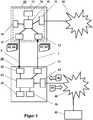
In der
Das Feldgerät
Darüber hinaus ist das Feldgerät
Erfindungsgemäß weist das Feldgerät
Das Bediengerät
Der Umfang der notwendigen Mittel des Bediengerät
Typischerweise sind bei bekannten Smartphones oder Tablet-Computer die Kamera
Vorteilhafterweise ist die Hardware des Bediengerät
Die Kommunikationsschnittstelle
Die erfindungsgemäße Kommunikationsanordnung ist gekennzeichnet durch eine bidirektionale Kommunikation zwischen dem Feldgerät
Der erste Übertragungsweg
In einer ersten Ausführungsform ist die Signalübertragung über den ersten Übertragungsweg
In einer alternativen Ausführungsform ist die Signalübertragung über den ersten Übertragungsweg
Der zweite Übertragungsweg
Der auf dem Display
Die Signalübertragung erfolgt auf beiden Übertragungswegen
In der
In einem zweiten Schritt
Die ausgewählten Feldgerätedaten
Im folgenden Schritt
In Abhängigkeit von den physikalischen Eigenschaften, wie Größe und Auflösung, des Displays
Unabhängig von der Aufteilung der Sendung in Datenpakete
Abscließend werden die Feldgerätedaten
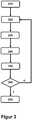
In der
In Schritt
Die codierten Aktualisierungsdaten
In Abhängigkeit von den Ergebnissen der Prüfung und Plausibilisierung der empfangenen Aktualisierungsdaten
Im folgenden Schritt
In Abhängigkeit vom Quittungssignal
Bei vollständig und unversehrt vom Feldgerät
In
Die Feldgerätedaten
Die Nachricht wird in Schritt
In Schritt
In Schritt
In Schritt
Anschließend werden die neuen Aktualisierungsdaten
In der
In Abhängigkeit von den physikalischen Eigenschaften, wie Größe und Auflösung, des Displays
Im Bediengerät
BezugszeichenlisteLIST OF REFERENCE NUMBERS
- 1,21.2
- Übertragungswegtransmission path
- 1010
- Feldgerätfield device
- 1111
- Elektronische SchaltungElectronic switch
- 1212
- Signalempfängersignal receiver
- 1313
- ProzesssteuerungsschnittstelleProcess control interface
- 1414
- Umformerconverter
- 1515
- Mikrocontrollermicrocontroller
- 1616
- DatenspeicherschaltungData storage circuit
- 1717
- Displaydisplay
- 2020
- Bediengerätcontrol unit
- 2121
- Signalgebersignaler
- 2222
- Kameracamera
- 2323
- Verarbeitungseinheitprocessing unit
- 2424
- GSM-SchnittstelleGSM interface
- 2525
- SpeicherStorage
- 2626
- Mensch-Maschine-SchnittstelleHuman-machine interface
- 3030
- ProzesssteuerungsnetzwerkProcess control network
- 4040
- GSM-NetzwerkGSM network
- 5050
- Entfernte EinrichtungRemote facility
- 6161
- Anforderungssignalrequest signal
- 6262
- Codierte FeldgerätedatenEncoded field device data
- 6363
- Codierte AktualisierungsdatenCoded update data
- 6464
- Quittungssignalacknowledgment signal
- 6565
- FeldgerätedatenField device data
- 6666
- Aktualisierungsdatenupdate data
- 6767
- Datenpaketdata packet
- 6868
- Codiertes QuittungssignalCoded acknowledgment signal
- 100..350100..350
- Verfahrensschrittesteps
ZITATE ENTHALTEN IN DER BESCHREIBUNG QUOTES INCLUDE IN THE DESCRIPTION
Diese Liste der vom Anmelder aufgeführten Dokumente wurde automatisiert erzeugt und ist ausschließlich zur besseren Information des Lesers aufgenommen. Die Liste ist nicht Bestandteil der deutschen Patent- bzw. Gebrauchsmusteranmeldung. Das DPMA übernimmt keinerlei Haftung für etwaige Fehler oder Auslassungen.This list of the documents listed by the applicant has been generated automatically and is included solely for the better information of the reader. The list is not part of the German patent or utility model application. The DPMA assumes no liability for any errors or omissions.
Zitierte PatentliteraturCited patent literature
- EP 1473685 B1 [0016]EP 1473685 B1 [0016]
- US 2017/0052524 A1 [0017]US 2017/0052524 A1 [0017]
- DE 102013013299 A1 [0017]DE 102013013299 A1 [0017]
- WO 2014/094981 A2 [0017]WO 2014/094981 A2 [0017]
- EP 2598961 A1 [0017]EP 2598961 A1 [0017]
- DE 202012007844 U1 [0018]DE 202012007844 U1 [0018]
- DE 202012009447 U1 [0018]DE 202012009447 U1 [0018]
- DE 102009055093 A1 [0018, 0019]DE 102009055093 A1 [0018, 0019]
Claims (12)
Translated fromGermanPriority Applications (1)
| Application Number | Priority Date | Filing Date | Title |
|---|---|---|---|
| DE102018109778.6ADE102018109778A1 (en) | 2018-04-24 | 2018-04-24 | Communication arrangement and method for its operation |
Applications Claiming Priority (1)
| Application Number | Priority Date | Filing Date | Title |
|---|---|---|---|
| DE102018109778.6ADE102018109778A1 (en) | 2018-04-24 | 2018-04-24 | Communication arrangement and method for its operation |
Publications (1)
| Publication Number | Publication Date |
|---|---|
| DE102018109778A1true DE102018109778A1 (en) | 2019-10-24 |
Family
ID=68105008
Family Applications (1)
| Application Number | Title | Priority Date | Filing Date |
|---|---|---|---|
| DE102018109778.6AWithdrawnDE102018109778A1 (en) | 2018-04-24 | 2018-04-24 | Communication arrangement and method for its operation |
Country Status (1)
| Country | Link |
|---|---|
| DE (1) | DE102018109778A1 (en) |
Citations (15)
| Publication number | Priority date | Publication date | Assignee | Title |
|---|---|---|---|---|
| EP1473685A2 (en) | 2003-04-30 | 2004-11-03 | Fisher-Rosemount Systems, Inc. | Intrinsically safe field maintenance tool |
| DE102005038607A1 (en)* | 2005-08-16 | 2007-02-22 | Vega Grieshaber Kg | Field equipment e.g. for ultrasound sensor operation in process automation, has detector for detection of first acoustic signal with control unit executing work procedure as reaction to detected first acoustic signal |
| EP2306648A1 (en)* | 2009-10-02 | 2011-04-06 | Siemens Aktiengesellschaft | Duplex data transfer via portable electronic device and field device |
| DE102009055093A1 (en) | 2009-12-21 | 2011-06-22 | Endress + Hauser Conducta Gesellschaft für Mess- und Regeltechnik mbH + Co. KG, 70839 | Field device for measuring and/or monitoring e.g. physical and/or measuring variable e.g. concentration of magnesium ion, has display unit selectively representing digital measurement data as alphanumeric character or machine-readable code |
| DE202012007844U1 (en) | 2012-08-17 | 2012-09-07 | Abb Ag | Automation device and information system |
| DE202012009447U1 (en) | 2012-10-01 | 2012-10-12 | Abb Technology Ag | field device |
| EP2598961A2 (en) | 2010-07-28 | 2013-06-05 | Fisher-Rosemount Systems, Inc. | Handheld field maintenance tool with field device simulation capability |
| DE102012112160A1 (en)* | 2012-12-12 | 2014-06-12 | Endress + Hauser Wetzer Gmbh + Co. Kg | Method for non-visual optical transfer of data by field device e.g. level measuring device, involves transferring a temporary non-visual optical signal for the transfer of data by field device |
| WO2014094981A2 (en) | 2012-12-20 | 2014-06-26 | Abb Ag | Process automation system and commissioning method for a field device in a process automation system |
| DE102013013299A1 (en) | 2013-08-12 | 2015-02-12 | Endress + Hauser Conducta Gesellschaft für Mess- und Regeltechnik mbH + Co. KG | Method for operating a field device |
| DE102013013365A1 (en)* | 2013-08-13 | 2015-02-19 | Endress + Hauser Flowtec Ag | Method for transmitting field device related additional information |
| DE102014208839A1 (en)* | 2014-05-12 | 2015-11-12 | Robert Bosch Gmbh | Method for secure data transmission between an automation system and an IT component |
| DE102014115514B3 (en)* | 2014-10-24 | 2016-04-14 | Krohne Messtechnik Gmbh | Method for connecting a field device with a control unit and field device |
| DE102016010800A1 (en)* | 2016-04-28 | 2016-12-08 | Wika Alexander Wiegand Se & Co. Kg | Virtual function modules for measuring instruments and plant components |
| US20170052524A1 (en) | 2015-08-21 | 2017-02-23 | Metso Automation Usa Inc. | Apparatus and method for universal setup, monitoring and control of field devices for a plant |
- 2018
- 2018-04-24DEDE102018109778.6Apatent/DE102018109778A1/ennot_activeWithdrawn
Patent Citations (16)
| Publication number | Priority date | Publication date | Assignee | Title |
|---|---|---|---|---|
| EP1473685A2 (en) | 2003-04-30 | 2004-11-03 | Fisher-Rosemount Systems, Inc. | Intrinsically safe field maintenance tool |
| EP1473685B1 (en) | 2003-04-30 | 2010-01-20 | Fisher-Rosemount Systems, Inc. | Intrinsically safe field maintenance tool |
| DE102005038607A1 (en)* | 2005-08-16 | 2007-02-22 | Vega Grieshaber Kg | Field equipment e.g. for ultrasound sensor operation in process automation, has detector for detection of first acoustic signal with control unit executing work procedure as reaction to detected first acoustic signal |
| EP2306648A1 (en)* | 2009-10-02 | 2011-04-06 | Siemens Aktiengesellschaft | Duplex data transfer via portable electronic device and field device |
| DE102009055093A1 (en) | 2009-12-21 | 2011-06-22 | Endress + Hauser Conducta Gesellschaft für Mess- und Regeltechnik mbH + Co. KG, 70839 | Field device for measuring and/or monitoring e.g. physical and/or measuring variable e.g. concentration of magnesium ion, has display unit selectively representing digital measurement data as alphanumeric character or machine-readable code |
| EP2598961A2 (en) | 2010-07-28 | 2013-06-05 | Fisher-Rosemount Systems, Inc. | Handheld field maintenance tool with field device simulation capability |
| DE202012007844U1 (en) | 2012-08-17 | 2012-09-07 | Abb Ag | Automation device and information system |
| DE202012009447U1 (en) | 2012-10-01 | 2012-10-12 | Abb Technology Ag | field device |
| DE102012112160A1 (en)* | 2012-12-12 | 2014-06-12 | Endress + Hauser Wetzer Gmbh + Co. Kg | Method for non-visual optical transfer of data by field device e.g. level measuring device, involves transferring a temporary non-visual optical signal for the transfer of data by field device |
| WO2014094981A2 (en) | 2012-12-20 | 2014-06-26 | Abb Ag | Process automation system and commissioning method for a field device in a process automation system |
| DE102013013299A1 (en) | 2013-08-12 | 2015-02-12 | Endress + Hauser Conducta Gesellschaft für Mess- und Regeltechnik mbH + Co. KG | Method for operating a field device |
| DE102013013365A1 (en)* | 2013-08-13 | 2015-02-19 | Endress + Hauser Flowtec Ag | Method for transmitting field device related additional information |
| DE102014208839A1 (en)* | 2014-05-12 | 2015-11-12 | Robert Bosch Gmbh | Method for secure data transmission between an automation system and an IT component |
| DE102014115514B3 (en)* | 2014-10-24 | 2016-04-14 | Krohne Messtechnik Gmbh | Method for connecting a field device with a control unit and field device |
| US20170052524A1 (en) | 2015-08-21 | 2017-02-23 | Metso Automation Usa Inc. | Apparatus and method for universal setup, monitoring and control of field devices for a plant |
| DE102016010800A1 (en)* | 2016-04-28 | 2016-12-08 | Wika Alexander Wiegand Se & Co. Kg | Virtual function modules for measuring instruments and plant components |
Similar Documents
| Publication | Publication Date | Title |
|---|---|---|
| EP2984530B1 (en) | Measuring transducer feed unit, system for use in automation technology, and method for operating such a system | |
| DE102010042116A1 (en) | Method for enabling prompt diagnosis, field device connected to a wireless adapter | |
| EP3070556B1 (en) | Method, computing device, user unit and system for parameterizing an electrical apparatus | |
| DE102013204535A1 (en) | Bus sharing unit i.e. actuator sensor-interface-process field network-gateway, for e.g. controlling field bus devices of automation technology, has display displaying codes with information of Internet protocol address and serial number | |
| DE102012016266A1 (en) | Sensor device of automation and/or industrial equipment, has memory device having nonvolatile memory from which data of master-slave bus system of microprocessor is readable and is serially transmitted to display device | |
| DE102014001462B4 (en) | Field bus module, machine control and method for parameterizing an, in particular safety-related, field bus module | |
| DE102008038415A1 (en) | Method for monitoring the state of charge or the residual capacity of a battery or a battery in automation technology | |
| DE102013013365A1 (en) | Method for transmitting field device related additional information | |
| DE102017005768A1 (en) | System of automation components and methods of operation | |
| DE102011106687A1 (en) | Signal processing system and method for processing signals in a bus node | |
| DE102019116193A1 (en) | Field device of automation technology | |
| DE102018118873A1 (en) | Electronic switching device for automation technology and optical receiver | |
| DE102018109778A1 (en) | Communication arrangement and method for its operation | |
| DE102014016180A1 (en) | Method and device for managing and configuring field devices of an automation system | |
| DE102008050612A1 (en) | Method for testing the behavior of a process plant | |
| DE102013009862A1 (en) | Sensor arrangement and method for operating a sensor arrangement | |
| DE102005043489B4 (en) | Automation device | |
| EP2187278A1 (en) | Control connection for a safety switch device | |
| EP2876514A1 (en) | Loop test of the functionality of technical equipment of an industrial process automation system | |
| EP3983858B1 (en) | Method for providing a digital twin for a nondigital automation engineering field device | |
| EP4006498A1 (en) | Start-up and maintenance of sensor and measuring transducer | |
| EP1899772B1 (en) | Method for operation of a data storage unit for process automation | |
| DE102021001276A1 (en) | Connection of input and/or output modules to a fieldbus with a higher-level controller | |
| DE102017208827A1 (en) | Distributed processing of process data | |
| EP2767019A1 (en) | Method for transmitting data in messages |
Legal Events
| Date | Code | Title | Description |
|---|---|---|---|
| R012 | Request for examination validly filed | ||
| R082 | Change of representative | Representative=s name:MARKS, FRANK DIETER, DIPL.-ING. PAT.-ING., DE | |
| R120 | Application withdrawn or ip right abandoned |