DE102018106051A1 - Combustion chamber assembly with burner seal and nozzle and a Leitströmungserzeugungseinrichtung - Google Patents
Combustion chamber assembly with burner seal and nozzle and a LeitströmungserzeugungseinrichtungDownload PDFInfo
- Publication number
- DE102018106051A1 DE102018106051A1DE102018106051.3ADE102018106051ADE102018106051A1DE 102018106051 A1DE102018106051 A1DE 102018106051A1DE 102018106051 ADE102018106051 ADE 102018106051ADE 102018106051 A1DE102018106051 A1DE 102018106051A1
- Authority
- DE
- Germany
- Prior art keywords
- nozzle
- air
- combustion chamber
- flow
- radially
- Prior art date
- Legal status (The legal status is an assumption and is not a legal conclusion. Google has not performed a legal analysis and makes no representation as to the accuracy of the status listed.)
- Withdrawn
Links
- 238000002485combustion reactionMethods0.000titleclaimsabstractdescription71
- 239000000203mixtureSubstances0.000claimsabstractdescription56
- 239000000446fuelSubstances0.000claimsabstractdescription30
- 108090000623proteins and genesProteins0.000claims1
- 239000012530fluidSubstances0.000description6
- 238000007789sealingMethods0.000description5
- 239000000243solutionSubstances0.000description5
- 238000001816coolingMethods0.000description4
- 239000007789gasSubstances0.000description3
- 101100116570Caenorhabditis elegans cup-2 geneProteins0.000description2
- 101100116572Drosophila melanogaster Der-1 geneProteins0.000description2
- 230000015572biosynthetic processEffects0.000description2
- 238000002347injectionMethods0.000description2
- 239000007924injectionSubstances0.000description2
- BUHVIAUBTBOHAG-FOYDDCNASA-N(2r,3r,4s,5r)-2-[6-[[2-(3,5-dimethoxyphenyl)-2-(2-methylphenyl)ethyl]amino]purin-9-yl]-5-(hydroxymethyl)oxolane-3,4-diolChemical compoundCOC1=CC(OC)=CC(C(CNC=2C=3N=CN(C=3N=CN=2)[C@H]2[C@@H]([C@H](O)[C@@H](CO)O2)O)C=2C(=CC=CC=2)C)=C1BUHVIAUBTBOHAG-FOYDDCNASA-N0.000description1
- 241001156002Anthonomus pomorumSpecies0.000description1
- 239000000470constituentSubstances0.000description1
- 238000002955isolationMethods0.000description1
- 238000012423maintenanceMethods0.000description1
- 238000004519manufacturing processMethods0.000description1
- 238000012986modificationMethods0.000description1
- 230000004048modificationEffects0.000description1
- 239000004071sootSubstances0.000description1
- 239000007921spraySubstances0.000description1
- 239000013589supplementSubstances0.000description1
Images


Classifications
- F—MECHANICAL ENGINEERING; LIGHTING; HEATING; WEAPONS; BLASTING
- F23—COMBUSTION APPARATUS; COMBUSTION PROCESSES
- F23R—GENERATING COMBUSTION PRODUCTS OF HIGH PRESSURE OR HIGH VELOCITY, e.g. GAS-TURBINE COMBUSTION CHAMBERS
- F23R3/00—Continuous combustion chambers using liquid or gaseous fuel
- F23R3/28—Continuous combustion chambers using liquid or gaseous fuel characterised by the fuel supply
- F23R3/283—Attaching or cooling of fuel injecting means including supports for fuel injectors, stems, or lances
- F—MECHANICAL ENGINEERING; LIGHTING; HEATING; WEAPONS; BLASTING
- F02—COMBUSTION ENGINES; HOT-GAS OR COMBUSTION-PRODUCT ENGINE PLANTS
- F02C—GAS-TURBINE PLANTS; AIR INTAKES FOR JET-PROPULSION PLANTS; CONTROLLING FUEL SUPPLY IN AIR-BREATHING JET-PROPULSION PLANTS
- F02C7/00—Features, components parts, details or accessories, not provided for in, or of interest apart form groups F02C1/00 - F02C6/00; Air intakes for jet-propulsion plants
- F02C7/28—Arrangement of seals
- F—MECHANICAL ENGINEERING; LIGHTING; HEATING; WEAPONS; BLASTING
- F02—COMBUSTION ENGINES; HOT-GAS OR COMBUSTION-PRODUCT ENGINE PLANTS
- F02C—GAS-TURBINE PLANTS; AIR INTAKES FOR JET-PROPULSION PLANTS; CONTROLLING FUEL SUPPLY IN AIR-BREATHING JET-PROPULSION PLANTS
- F02C9/00—Controlling gas-turbine plants; Controlling fuel supply in air- breathing jet-propulsion plants
- F02C9/26—Control of fuel supply
- F02C9/263—Control of fuel supply by means of fuel metering valves
- F—MECHANICAL ENGINEERING; LIGHTING; HEATING; WEAPONS; BLASTING
- F23—COMBUSTION APPARATUS; COMBUSTION PROCESSES
- F23R—GENERATING COMBUSTION PRODUCTS OF HIGH PRESSURE OR HIGH VELOCITY, e.g. GAS-TURBINE COMBUSTION CHAMBERS
- F23R3/00—Continuous combustion chambers using liquid or gaseous fuel
- F23R3/28—Continuous combustion chambers using liquid or gaseous fuel characterised by the fuel supply
- F23R3/286—Continuous combustion chambers using liquid or gaseous fuel characterised by the fuel supply having fuel-air premixing devices
- F—MECHANICAL ENGINEERING; LIGHTING; HEATING; WEAPONS; BLASTING
- F23—COMBUSTION APPARATUS; COMBUSTION PROCESSES
- F23R—GENERATING COMBUSTION PRODUCTS OF HIGH PRESSURE OR HIGH VELOCITY, e.g. GAS-TURBINE COMBUSTION CHAMBERS
- F23R2900/00—Special features of, or arrangements for continuous combustion chambers; Combustion processes therefor
- F23R2900/00012—Details of sealing devices
Landscapes
- Engineering & Computer Science (AREA)
- Chemical & Material Sciences (AREA)
- Combustion & Propulsion (AREA)
- Mechanical Engineering (AREA)
- General Engineering & Computer Science (AREA)
- Processes For Solid Components From Exhaust (AREA)
Abstract
Translated fromGerman
Description
Translated fromGermanDie vorgeschlagene Lösung betrifft eine Brennkammerbaugruppe mit einer Brennerdichtung und einer Düse für eine Brennkammer eines Triebwerks zur Bereitstellung eines Kraftstoff-Luft-Gemisches an einer Düsenaustrittsöffnung der Düse.The proposed solution relates to a combustion chamber assembly having a burner seal and a nozzle for a combustion chamber of an engine for providing a fuel-air mixture at a nozzle outlet opening of the nozzle.
Eine (Einspritz-) Düse für eine Brennkammer eines Triebwerks, insbesondere für eine Ringbrennkammer eines Gasturbinentriebwerks umfasst einen die Düsenaustrittsöffnung aufweisenden Düsenhauptkörper, der neben einem Kraftstoffleitkanal zur Förderung von Kraftstoff an die Düsenaustrittsöffnung mehrere (mindestens zwei) Luftleitkanäle zur Förderung von mit dem Kraftstoff zu vermischender Luft an die Düsenaustrittsöffnung aufweist. Eine Düse dient üblicherweise auch zum Verdrallen der zugeführten Luft, die dann, mit dem zugeführten Kraftstoff gemischt, an der Düsenaustrittsöffnung der Düse in die Brennkammer gefördert wird und ist in einer Durchgangsöffnung einer Brennerdichtung gehalten. Mehrere Düsen sind beispielsweise in einer Düsenbaugruppe einer Brennkammerbaugruppe zusammengefasst, die mehrere nebeneinander, üblicherweise entlang einer Kreislinie angeordnete Düsen zur Einbringung von Kraftstoff in die Brennkammer umfasst.An (injection) nozzle for a combustion chamber of an engine, in particular for a ring combustion chamber of a gas turbine engine comprises a nozzle main body having the nozzle outlet opening, in addition to a Kraftstoffleitkanal for conveying fuel to the nozzle outlet opening a plurality (at least two) Luftleitkanäle for conveying to be mixed with the fuel Having air at the nozzle exit opening. A nozzle usually also serves to distort the supplied air, which is then mixed with the supplied fuel, is conveyed to the nozzle outlet opening of the nozzle in the combustion chamber and is held in a through hole of a burner seal. A plurality of nozzles are, for example, combined in a nozzle assembly of a combustion chamber assembly comprising a plurality of juxtaposed, usually along a circular line nozzles for introducing fuel into the combustion chamber.
Aus dem Stand der Technik, zum Beispiel der
Aus dem Stand der Technik ist ferner bekannt, an einem im Bereich der Düsenaustrittsöffnung liegenden Ende eines radial außen liegenden Luftleitkanals ein Luftleitelement zur Führung aus dem mindestens einen weiteren Luftleitkanal strömender Luft vorzusehen. Über ein solches Luftleitelement wird die aus dem weiteren Luftleitkanal ausströmende, üblicherweise verdrallte Luft radial nach innen umgelenkt, um eine Vermischung mit dem Kraftstoff aus dem Kraftstoffleitkanal und der zusätzlichen Luft insbesondere aus dem ersten, inneren Luftleitkanal zu erreichen. Hierüber soll eine Spraywolke mit Kraftstoff-Luft-Gemisch erzeugt werden, in der der Kraftstoff in fein verteilten Tropfen vorliegt.From the prior art it is also known to provide at an end of a radially outer air duct lying in the region of the nozzle outlet opening an air guide element for guiding air flowing from the at least one further air duct. About such a spoiler, the flowing out of the further air duct, usually twisted air is deflected radially inwardly to achieve mixing with the fuel from the Kraftstoffleitkanal and the additional air in particular from the first, inner air duct. Over this a spray cloud with fuel-air mixture is to be produced, in which the fuel is present in finely divided drops.
Ferner wird über das Luftleitelement die an der Düsenaustrittsöffnung austretende Luft und das an der Düsenaustrittsöffnung austretende Kraftstoff-Luft-Gemisch in eine radial nach außen weisende Abströmrichtung geführt. Diese bereits teilweise durch das Luftleitelement an dem Düsenhauptkörper vorgegebene Abströmrichtung wird üblicherweise durch ein Strömungsleitelement an der Brennerdichtung (zusätzlich) gesteuert. Ein solches Strömungsleitelement ist durch einen axialen Überstand an der Brennerdichtung ausgebildet, der bei bestimmungsgemäß montierter Brennkammerbaugruppe in Richtung der Brennkammer ragt und typischerweise einen radial nach außen weisenden, sich aufweitenden Endabschnitt aufweist. Die gezielte Führung der an der Düsenaustrittsöffnung austretenden Luft und insbesondere des an der Düsenaustrittsöffnung austretenden Kraftstoff-Luft-Gemisches beeinflusst maßgeblich die Durchmischung in dem Kraftstoff-Luft-Gemisch und hierüber die bei der Verbrennung entstehenden Emissionen, insbesondere die Rußbildung. Im Betrieb des Triebwerks ist ein Strömungsleitelement der Brennerdichtung den hohen in der Brennkammer herrschenden Temperaturen ausgesetzt und muss daher häufig aufwendig gekühlt werden. Dennoch kommt es nicht selten zu temperaturbedingten Beschädigungen und Verschleißerscheinungen an einem Strömungsleitelement der Brennerdichtung. Regelmäßig ist dann ein Austausch der Brennerdichtung notwendig.Furthermore, the air exiting at the nozzle outlet opening and the fuel-air mixture exiting at the nozzle outlet opening are guided via the air guide element into a discharge direction pointing radially outward. This outflow direction, which is already partly predetermined by the air guiding element on the nozzle main body, is usually (additionally) controlled by a flow guiding element on the burner sealing device. Such a flow guide element is formed by an axial projection on the burner seal, which projects in the direction of the combustion chamber when the combustion chamber assembly is mounted as intended and typically has a radially outwardly pointing, widening end section. The targeted guidance of the emerging at the nozzle outlet opening air and in particular the exiting at the nozzle outlet opening fuel-air mixture significantly influences the mixing in the fuel-air mixture and hereby the resulting emissions during combustion, in particular the formation of soot. During operation of the engine, a flow-guiding element of the burner seal is exposed to the high temperatures prevailing in the combustion chamber and therefore often has to be laboriously cooled. Nevertheless, it is not uncommon for temperature-related damage and wear on a flow guide of the burner seal. Regularly then an exchange of the burner seal is necessary.
Es besteht somit Bedarf an einer in dieser Hinsicht verbesserten Brennkammerbaugruppe.Thus, there is a need for an improved combustor assembly in this regard.
Diese Aufgabe ist mit einer Brennkammerbaugruppe nach Anspruch 1 gelöst.This object is achieved with a combustion chamber assembly according to claim 1.
Hiernach ist eine Brennkammerbaugruppe mit einer Düse und einer Brennerdichtung vorgeschlagen, bei der die Düse einen die Düsenaustrittsöffnung aufweisenden Düsenhauptkörper umfasst, der sich entlang einer Düsenlängsachse erstreckt und der wenigstens das Folgende umfasst:
- - mindestens einen sich entlang der Düsenlängsachse erstreckenden (ersten) inneren Luftleitkanal zur Förderung von Luft an die Düsenaustrittsöffnung,
- - mindestens einen gegenüber dem inneren Luftleitkanal, bezogen auf die Düsenlängsachse, radial weiter außen liegenden Kraftstoffleitkanal zur Förderung von Kraftstoff an die Düsenaustrittsöffnung und
- - mindestens ein gegenüber dem inneren Luftleitkanal und dem Kraftstoffleitkanal, bezogen auf die Düsenlängsachse, radial außen liegendes Luftleitelement zur Führung an der Düsenaustrittsöffnung austretender Luft und des an der Düsenaustrittsöffnung austretenden Kraftstoff-Luft-Gemisches in eine radial nach außen weisende Abströmrichtung.
- at least one (first) inner air duct extending along the nozzle longitudinal axis for conveying air to the nozzle outlet opening,
- - at least one relative to the inner air duct, with respect to the nozzle longitudinal axis, radially further outward Kraftstoffleitkanal for conveying fuel to the nozzle outlet opening and
- - At least one relative to the inner air duct and the Kraftstoffleitkanal, relative to the nozzle longitudinal axis, radially outwardly disposed air guide for guiding at the nozzle exit opening exiting air and exiting at the nozzle exit opening fuel-air mixture in a radially outwardly facing discharge direction.
Zusätzlich zu dem mindestens einen Luftleitelement ist eine Leitströmungserzeugungseinrichtung vorgesehen, die eingerichtet ist, wenigstens eine Leitströmung zu erzeugen, die an der Düsenaustrittsöffnung austretende Luft und das an der Düsenaustrittsöffnung austretende Kraftstoff-Luft-Gemisch radial berandet und einen maximalen Abströmwinkel für die Abströmrichtung bezüglich der Düsenlängsachse vorgibt und begrenzt, unter dem an der Düsenaustrittsöffnung austretende Luft und das an der Düsenaustrittsöffnung austretende Kraftstoff-Luft-Gemisch radial nach außen abströmen kann.In addition to the at least one air guide element, a guide flow generating device is provided, which is configured to generate at least one guide flow, the radially emerging at the nozzle outlet opening and the air exiting at the nozzle outlet opening fuel-air mixture and a maximum outflow angle for the outflow direction with respect to the nozzle longitudinal axis predetermines and limits, under the exiting at the nozzle outlet opening air and the exiting at the nozzle outlet opening fuel-air mixture can flow radially outward.
Im Rahmen der vorgeschlagenen Lösung ist somit beispielsweise zusätzlich zu einem radial außen liegenden und gegebenenfalls axial vorstehenden Luftleitelement des Düsenhauptkörpers eine Leitströmungserzeugungseinrichtung an der Düse und/oder der Brennerdichtung der Brennkammerbaugruppe vorgesehen, die eingerichtet ist, wenigstens eine Leitströmung aus Luft oder einem anderen Fluid zu erzeugen um insbesondere das an der Düsenaustrittsöffnung austretende Kraftstoff-Luft-Gemisch innerhalb eines vorgegebenen Abströmwinkels, sowie gegebenenfalls eines hierdurch definierten Abströmkegels, zu halten. Die durch die Leitströmungserzeugungseinrichtung erzeugte Leitströmung gibt dann den Abströmwinkel vor, unter dem eine Strömung aus der an der Düsenaustrittsöffnung austretenden Luft und insbesondere des an der Düsenaustrittsöffnung austretenden Kraftstoff-Luft-Gemisches maximal geneigt zur Düsenlängsachse radial nach außen verlaufen kann. Die Leitströmung gibt somit eine maximal zu Düsenlängsachse geneigte Abströmrichtung vor, der ein äußerster Rand der Strömung aus der Düsenaustrittsöffnung austretender Luft und des an der Düsenaustrittsöffnung austretenden Kraftstoff-Luft-Gemisches folgt.In the proposed solution, for example, in addition to a radially outer and optionally axially projecting air guide of the nozzle main body a Leitströmungserzeugungseinrichtung is provided on the nozzle and / or the burner seal of the combustion chamber assembly, which is adapted to generate at least one Leitströmung of air or other fluid in particular in order to keep the fuel-air mixture emerging at the nozzle outlet opening within a predetermined outflow angle and, if appropriate, an outflow cone defined thereby. The guide flow generated by the Leitströmungserzeugungseinrichtung then specifies the outflow angle, below which a flow of the emerging at the nozzle outlet opening air and in particular the exiting at the nozzle exit opening fuel-air mixture maximum inclined to the nozzle longitudinal axis can extend radially outward. The guide flow thus provides a maximum outflow direction inclined to the nozzle longitudinal axis, which follows an outermost edge of the flow out of the nozzle outlet opening exiting air and exiting at the nozzle outlet opening fuel-air mixture.
Über eine gezielt erzeugte Leitströmung wird somit insbesondere dem austretenden Kraftstoff-Luft-Gemisch eine bestimmte Abströmcharakteristik vorgegeben und eine Ausbreitung einer Gemischströmung des Kraftstoff-Luft-Gemisches - über den maximal zulässigen, durch die Leitströmung vorgegebenen Abströmwinkel - begrenzt. Dies schließt insbesondere die Erzeugung einer (Luft-) Leitströmung über die Leitströmungserzeugungseinrichtung ein, die einen Abströmkegel definiert, innerhalb dessen das an der Düsenaustrittsöffnung austretende Kraftstoffluft-Gemisch verbleibt. Ein radial außen liegendes Luftleitelement kann folglich zwar weiterhin, für Erzeugung des Kraftstoff-Luft-Gemischs, insbesondere zur Führung aus einem Luftleitkanal austretender Luft radial nach innen dienen sowie eine Führung des sich ergebenden Kraftstoff-Luft-Gemisches radial nach außen unterstützen. Ein zusätzliches Strömungsleitelement an der Brennerdichtung kann aber entfallen oder zumindest verkürzt werden, da die maßgebliche (weitere) Führung des Kraftstoff-Luft-Gemisches radial nach außen und die Begrenzung eines Abströmwinkels von einer gezielt über die Leitströmungserzeugungseinrichtung erzeugten Leitströmung übernommen wird.By means of a specifically generated guide flow, in particular the exiting fuel-air mixture is thus given a specific outflow characteristic and a spread of a mixture flow of the fuel-air mixture-above the maximum permissible outflow angle predetermined by the guide flow-is limited. This includes, in particular, the generation of an (air) guide flow via the guide flow generating device, which defines an outflow cone within which the fuel-air mixture emerging at the nozzle outlet opening remains. Consequently, a radially outer air-guiding element can continue to serve radially inward for generating the fuel-air mixture, in particular for guiding air ducts out of the air duct, and to support a guidance of the resulting fuel-air mixture radially outwards. However, an additional flow guide element on the burner seal can be dispensed with or at least shortened since the relevant (further) guidance of the fuel-air mixture is taken over radially outward and the limitation of an outflow angle from a guide flow generated specifically via the guide flow generation device.
Grundsätzlich kann die Düse der Brennkammerbaugruppe zusätzlich zu dem inneren (ersten) Luftleitkanal einen oder mehrere weitere (zweite und/oder dritte) radial weiter außen liegende Luftleitkanäle aufweisen. Ein Ende eines solchen Luftleitkanals, an dem die Luft aus dem jeweiligen Luftleitkanal in Richtung der Düsenaustrittsöffnung austritt, liegt dann gegenüber dem Luftleitelement radial weiter innen und die Luftströmungserzeugungseinrichtung ist stets zusätzlich zu dem inneren Luftleitkanal und etwaigen weiteren Luftleitkanälen vorgesehen.In principle, the nozzle of the combustion chamber assembly may have, in addition to the inner (first) air duct, one or more further (second and / or third) radially outer air ducts. One end of such an air duct, at which the air exits from the respective air duct in the direction of the nozzle outlet opening, then lies radially further inwards relative to the air duct and the air flow generator is always provided in addition to the inner air duct and any further air ducts.
In einer Ausführungsvariante weist die Düse zusätzlich zu dem inneren (ersten) Luftleitkanal mindestens einen weiteren (zweiten), radial weiter außen liegenden Luftleitkanal auf, an dessen Ende das mindestens eine Luftleitelement vorgesehen ist.In one embodiment variant, the nozzle has, in addition to the inner (first) air duct, at least one further (second), radially outer air duct, at the end of which the at least one air duct is provided.
Grundsätzlich kann die Leitströmungserzeugungseinrichtung zur Erzeugung einer radial äußersten und gegebenenfalls ein sich ergebendes Kraftstoff-Luft-Gemisch kreisringförmig einhüllenden Leitströmung eingerichtet und vorgesehen sein, um den maximalen Abströmwinkel für die radial nach außen weisende Abströmrichtung des Kraftstoff-Luft-Gemisches bezüglich der Düsenlängsachse vorzugeben und zu begrenzen. Hierfür kann die Leitströmungserzeugungsrichtung beispielsweise zumindest teilweise an der Düse und/oder anderer der Brennerdichtung vorgesehen sein.Basically, the Leitströmungserzeugungseinrichtung can be set up and provided to produce a radially outermost and possibly a resulting fuel-air mixture annular enveloping Leitströmung to specify the maximum outflow angle for the radially outward flow direction of the fuel-air mixture with respect to the nozzle longitudinal axis and to limit. For this purpose, the Leitströmungserzeugungsrichtung may for example be provided at least partially on the nozzle and / or other of the burner seal.
In einer Ausführungsvariante ist mindestens ein Bestandteil der Leitströmungserzeugungseinrichtung, insbesondere ein an der Erzeugung der Leitströmung mitwirkender Bestandteil, bezogen auf die Düsenlängsachse, gegenüber dem mindestens einen radial außen liegenden Luftleitelement radial weiter innen oder radial weiter außen vorgesehen. Ein radial weiter innen vorgesehener Bestandteil ist hierbei beispielsweise an der Düse und insbesondere an dem Düsenhauptkörper, während ein radial weiter außen vorgesehener Bestandteil an der Brennerdichtung vorgesehen ist.In one embodiment, at least one component of the Leitströmungserzeugungseinrichtung, in particular a cooperating in the generation of the Leitströmung component, relative to the nozzle longitudinal axis, with respect to the at least one radially outer air guide element radially further inside or radially further outside. A component provided radially further in this case is, for example, on the nozzle and in particular on the nozzle main body, while a radially further provided on the outside component is provided on the burner seal.
In einer Ausführungsvariante ist für die Erzeugung wenigstens eines Teils der Leitströmung mindestens eine Zuströmöffnung der Leitströmungserzeugungseinrichtung an der Brennerdichtung vorgesehen. Die Brennerdichtung integriert somit eine Zuströmöffnung, die als Bestandteil der Leitströmungserzeugungseinrichtung wirkt. Bei der Zuströmöffnung handelt es sich somit nicht um eine Kühlluftöffnung, um beispielsweise Kühlluft an ein Strömungsleitelement der Brennerdichtung heran zu führen. Durch die Zuströmöffnung einströmendes Fluid, insbesondere Luft dient hier vielmehr der Erzeugung der den maximalen Abströmwinkel vorgebenden und begrenzenden Leitströmung.In one embodiment variant, at least one inflow opening of the guide flow generating device is provided on the burner seal for generating at least part of the guide flow. The burner seal thus integrates an inflow opening, which acts as part of the guide flow generating device. The inflow opening is thus not a cooling air opening, for example, to lead cooling air to a flow guiding element of the burner seal. Instead, fluid flowing in through the inflow opening, in particular air, serves to generate the guiding flow which predetermines and limits the maximum outflow angle.
Die mindestens eine Zuströmöffnung kann hierbei beispielsweise eine zur Düsenlängsachse radial nach innen geneigte Strömungsrichtung für über die Zuströmöffnung einströmendes Fluid, insbesondere für über die Zuströmöffnung einströmende Luft vorgeben. Die Zuströmöffnung kann demzufolge beispielsweise einen Zuströmkanal definieren, der ein Fluid von außen durch die Brennerdichtung führt und entlang einer radial nach innen geneigten Strömungsrichtung ausströmen lässt.In this case, the at least one inflow opening can, for example, predefine a flow direction inclined radially inwardly to the nozzle longitudinal axis for fluid flowing in via the inflow opening, in particular for air flowing in via the inflow opening. Accordingly, the inflow opening can for example define an inflow channel, which leads a fluid from the outside through the burner seal and can flow out along a radially inwardly inclined flow direction.
In einer Weiterbildung ist die Zuströmöffnung alternativ oder ergänzend eingerichtet, über die Zuströmöffnung einströmendes Fluid, insbesondere über die Zuströmöffnung einströmende Luft in Richtung auf eine radial äußere Mantelfläche der Düse zu leiten. Beispielsweise ist die Zuströmöffnung eingerichtet, über die Zuströmöffnung einströmende Luft auf eine radial äußere Mantelfläche des radial außen liegenden Luftleitelements des Düsenhauptkörpers zu leiten. An dieser radial äußeren Mantelfläche des radial außen liegenden Luftleitelements kann die Strömung aus der Zuströmöffnung an der Brennerdichtung entlang geführt und/oder radial nach außen geführt werden, um einen Teil der Leitströmung zu definieren.In a development, the inflow opening is set up as an alternative or as a supplement to direct air flowing in via the inflow opening, in particular air flowing in via the inflow opening in the direction of a radially outer jacket face of the nozzle. For example, the inflow opening is set up to direct air flowing in via the inflow opening onto a radially outer circumferential surface of the radially outer air-guiding element of the nozzle main body. The flow from the inflow opening can be guided along the burner seal and / or guided radially outward on this radially outer jacket surface of the radially outer air-conducting element in order to define a part of the guide flow.
In einer hierauf basierenden Ausführungsvariante ist zwischen einem Strömungsleitelement der Brennerdichtung und einem Abschnitt der radial äußeren Mantelfläche der Düse ein Zusatzleitkanal gebildet und die Zuströmöffnung ist eingerichtet, über die Zuströmöffnung einströmendes Fluid, insbesondere über die Zuströmöffnung einströmende Luft in den Zusatzleitkanal zu leiten. Im Betrieb des Triebwerks wird somit mithilfe der Zuströmöffnung Luft in einen zwischen einem Strömungsleitelement der Brennerdichtung und einem Abschnitt der radial äußeren Mantelfläche gebildeten Zusatzleitkanal geleitet, an dessen Ende die Leitströmung oder zumindest ein Teil dieser Leitströmung unter dem vorgegebenen Abströmwinkel austritt. Dementsprechend kann sich der Zusatzleitkanal beispielsweise axial bezüglich der Düsenlängsachse erstrecken und zur Erzeugung der die Abströmrichtung und insbesondere den Abströmwinkel vorgebenden Leitströmung am Ende des Düsenhauptkörpers führen.In a variant embodiment based thereon, an additional guide channel is formed between a flow guide element of the burner seal and a section of the radially outer surface of the nozzle, and the inflow opening is adapted to guide the fluid flowing in via the inflow opening into the additional guide channel, in particular via the inflow opening. During operation of the engine, air is thus directed by means of the inflow opening into an auxiliary duct formed between a flow guide element of the burner seal and a section of the radially outer jacket surface, at the end of which the guide flow or at least part of this guide flow exits at the predetermined outflow angle. Accordingly, the additional guide channel may extend, for example, axially with respect to the longitudinal axis of the nozzle and lead to the production of the outflow direction and in particular the outflow angle predetermining guide flow at the end of the nozzle main body.
Ein für die Bildung des Zusatzleitkanals vorgesehenes Strömungsleitelement der Brennerdichtung kann an einem im Bereich der Düsenaustrittsöffnung liegenden Ende axial bezüglich der Düsenlängsachse verlaufen, d.h., ohne einen sich radial nach außen erstreckenden und sich radial nach außen aufweitenden Endabschnitt auszubilden, über den das aus der Düsenaustrittsöffnung austretende Kraftstoff-Luft-Gemisch geführt werden würde. Die Führung des Kraftstoff-Luft-Gemisches wird hier vielmehr über die aus dem Zusatzleitkanal austretende Leitströmung geleistet, sodass ein Strömungsleitelement der Brennerdichtung nur mit einer vergleichsweise geringen Länge in Richtung der Brennkammer axial vorragen muss. Ein temperaturbedingter Verschleiß des Strömungsleitelements aufgrund der in der Brennkammer herrschenden hohen Temperaturen lässt sich derart erheblich reduzieren oder sogar vermeiden.A provided for the formation of Zusatzleitkanals Strömungsleitelement the burner seal may extend at an end lying in the nozzle outlet opening axially with respect to the nozzle longitudinal axis, ie, without a radially outwardly extending and radially outwardly flared end form over which exiting the nozzle outlet opening Fuel-air mixture would be conducted. The leadership of the fuel-air mixture is here rather made on the emerging from the additional guide flow Leitströmung, so that a flow guide of the burner seal must protrude axially only with a comparatively short length in the direction of the combustion chamber. A temperature-induced wear of the flow-guiding element due to the high temperatures prevailing in the combustion chamber can thus be considerably reduced or even avoided.
In einer alternativen Ausführungsvariante weist die Brennerdichtung im Bereich der Düsenaustrittsöffnung kein Strömungsleitelement auf. Mithin weist die Brennerdichtung keinen axial vorstehenden Überstand auf, der bei bestimmungsgemäßer Montage der Brennkammerbaugruppe in Richtung einer Brennkammer des Triebwerks ragt, insbesondere über das Luftleitelement der Düse axial hinaus ragt. In einer solchen Variante wird die Führung des Kraftstoff-Luft-Gemisches nicht durch ein brennerdichtungsseitiges Strömungsleitelement, sondern vornehmlich von der mithilfe der Leitströmungserzeugungseinrichtung im Betrieb des Triebwerks erzeugten Leitströmung auf einen vorgegebenen Abströmwinkel begrenzt.In an alternative embodiment, the burner seal in the region of the nozzle outlet opening on no flow guide. Thus, the burner seal has no axially protruding projection, which protrudes in the intended assembly of the combustion chamber assembly in the direction of a combustion chamber of the engine, in particular projects beyond the air guide element of the nozzle axially. In such a variant, the guidance of the fuel-air mixture is not limited by a strömerdichtungsseitiges flow guide, but primarily by the Leitströmungserzeugseinrichtung generated during operation of the engine flow to a predetermined outflow angle.
Unabhängig davon, ob an der Brennerdichtung ein Strömungsleitelement vorgesehen ist oder nicht, kann in einer Ausführungsvariante für die Erzeugung wenigstens eines Teils der Leitströmung mindestens ein Führungselement der Leitströmungserzeugungseinrichtung an der Düse vorgesehen sein. Das Führungselement als Bestandteil der Leitströmungserzeugungseinrichtung ist hier folglich an der Düse und insbesondere als Teil des Düsenhauptkörpers ausgebildet, beispielsweise im Bereich der Düsenaustrittsöffnung.Regardless of whether or not a flow-guiding element is provided on the burner seal, in one embodiment for producing at least part of the guiding flow, at least one guiding element of the guiding-flow generating device can be provided on the nozzle. The guide element as a constituent of the guide flow generating device is therefore here formed on the nozzle and in particular as part of the nozzle main body, for example in the region of the nozzle outlet opening.
In einer hierauf basierenden Ausführungsvariante ist das mindestens eine Führungselement unter Bildung eines Luftleitspalts zu dem radial außen liegenden Luftleitelement beabstandet. Das mindestens eine Führungselement liegt somit gegenüber dem Luftleitelement radial weiter innen und bildet zusammen mit einem Abschnitt des Luftleitelements den Luftleitspalt. Dieser Luftleitspalt kann insbesondere sich düsenartig verengend ausgebildet sein, um eine entsprechend beschleunigte Luftströmung für die Leitströmung zu erzeugen. Hierbei ist die Düse ausgebildet und eingerichtet, aus wenigstens einem Luftleitkanal ausströmende Luft zu dem zwischen dem mindestens einen Führungselement und dem Luftleitelement gebildeten Luftleitspalt zu führen, aus dem dann ein Teil der den Abströmwinkel vorgebenden und begrenzenden Leitströmung austritt.In an embodiment based thereon, the at least one guide element is spaced apart from the radially outer air guide element to form an air-guiding gap. The at least one guide element thus lies radially further inward relative to the air guide element and forms together with a portion of the air guide the Luftleitspalt. In particular, this air-guiding gap can be designed to narrow in the manner of a nozzle in order to generate a correspondingly accelerated air flow for the guide flow. In this case, the nozzle is designed and set up to guide air flowing out of at least one air duct to the air-guiding gap formed between the at least one guide element and the air-guiding element, from which then a part of the outflow angle predetermining and limiting the conductive flow exits.
Mittels des mindestens einen Führungselements kann somit insbesondere ein Luftstrahl (englisch „air jet“) für die Leitströmung erzeugbar sein. Dieser Luftstrahl weist unter dem Abströmwinkel radial nach außen und begrenzt radial die an der Düsenaustrittsöffnung austretende Luft und das an der Düsenaustrittsöffnung austretende Kraftstoff-Luft-Gemisch. Der Luftstrahl tritt hierbei in einer Ausführungsvariante aus dem mithilfe des mindestens einen Führungselements gebildeten Luftleitspalts mit einer Strömungsgeschwindigkeit an der Düsenaustrittsöffnung aus, die höher - gegebenenfalls um wenigstens 3%, 5%, 10%, 15% oder 20% höher - ist als eine Strömungsgeschwindigkeit der an der Düsenaustrittsöffnung austretenden Luft und des an der Düsenaustrittsöffnung austretenden Kraftstoff-Luft-Gemisches. Das mindestens eine Führungselement ist somit zur Erzeugung eines Luftstrahls mit entsprechend erhöhter Strömungsgeschwindigkeit für die Leitströmung eingerichtet. Über das mindestens eine Führungselement wird hierbei ein Teil der an der Düsenaustrittsöffnung zur Verfügung stehenden und aus dem mindestens einen Luftleitkanal der Düse stammenden Luft entsprechend umgelenkt und beschleunigt, um hiermit die Leitströmung vorzugeben, die den maximalen Abströmwinkel vorgibt.By means of the at least one guide element can thus be generated in particular an air jet (English "air jet") for the guide flow. This jet of air points radially outward at the outflow angle and radially limits the air emerging at the nozzle outlet opening and the fuel-air mixture emerging at the nozzle outlet opening. In one embodiment variant, the air jet emerges from the air-guiding gap formed with the aid of the at least one guide element at a flow velocity at the nozzle outlet opening which is higher, possibly at least 3%, 5%, 10%, 15% or 20% higher, than a flow velocity the exiting at the nozzle outlet opening air and exiting at the nozzle outlet opening fuel-air mixture. The at least one guide element is thus set up to generate an air jet with a correspondingly increased flow velocity for the guide flow. By way of the at least one guide element, part of the air available at the nozzle outlet opening and originating from the at least one air duct of the nozzle is correspondingly deflected and accelerated, in order to predefine the pilot flow which predetermines the maximum outflow angle.
Im Zuge der vorgeschlagenen Lösung ist ferner ein Triebwerk, insbesondere ein Gasturbinentriebwerk mit mindestens einer Brennkammerbaugruppe vorgesehen.In the course of the proposed solution, an engine, in particular a gas turbine engine with at least one combustion chamber assembly is further provided.
Die beigefügten Figuren anschaulichen exemplarisch mögliche Ausführungsvarianten der vorgeschlagenen Lösung.The attached figures illustrate by way of example possible embodiments of the proposed solution.
Hierbei zeigen:
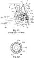
1 ausschnittsweise eine erste Ausführungsvariante einer vorgeschlagenen Brennkammerbaugruppe, mit einer Leitströmungserzeugungseinrichtung, die zur Erzeugung einer den radial Abströmwinkel eines Kraftstoff-Luft-Gemisches an einer Düsenaustrittsöffnungen begrenzenden Leitströmung einen Zusatzleitkanal zwischen einem verkürzten Strömungsleitelement einer Brennerdichtung und einer radial äußeren Mantelfläche einer Düse ausbildet;2 in mit der1 übereinstimmender Ansicht eine weitere Ausführungsvariante einer vorgeschlagenen Brennkammerbaugruppe, mit einer Brennerdichtung ohne Strömungsleitelement und einem düsenseitigen Führungselement einer Leitströmungserzeugungseinrichtung zur Erzeugung eines radial nach außen gerichteten Luftstrahls für die Leitströmung;3A ein Triebwerk, in dem die Ausführungsvarianten der1 bis6 zum Einsatz kommt;3B ausschnittsweise und in vergrößertem Maßstab die Brennkammer des Triebwerks der3A ;3C in Querschnittsansicht den grundsätzlichen Aufbau einer Düse gemäß dem Stand der Technik und die umliegenden Komponenten des Triebwerks im eingebauten Zustand der Düse;3D eine Rückansicht auf eine Düsenaustrittsöffnung unter Darstellung von Verdrallelementen, die in radial außen liegenden Luftleitkanälen der Düse vorgesehen sind.
1 a detail of a first embodiment of a proposed combustion chamber assembly, with a Leitströmungserzeugungseinrichtung, which forms an additional duct between a shortened flow guide a burner seal and a radially outer surface of a nozzle to produce a radial outflow angle of a fuel-air mixture at a nozzle outlet openings limiting Leitström;2 in with the1 a further embodiment variant of a proposed combustion chamber assembly, with a burner seal without flow guide and a nozzle-side guide element of a Leitströmungserzeugungseinrichtung for generating a radially outwardly directed air jet for the Leitströmung;3A an engine in which the variants of the1 to6 is used;3B fragmentary and on an enlarged scale the combustion chamber of the engine3A ;3C in cross-sectional view of the basic structure of a nozzle according to the prior art and the surrounding components of the engine in the installed state of the nozzle;3D a rear view of a nozzle outlet opening showing Verdrallelementen which are provided in radially outer air ducts of the nozzle.
Die
Die über den Verdichter
Die
Die
Die Düse
Des Weiteren ist wenigstens ein Kraftstoffleitkanal
In den äußeren Luftleitkanälen
Zur Abdichtung der Düse
Die Brennerdichtung
Bei einer aus dem Stand der Technik bekannten Brennkammerbaugruppe gemäß der
Da das Strömungsleitelement
In dieser Hinsicht kann eine vorgeschlagene Brennkammerbaugruppe Abhilfe schaffen. Hierbei wird zusätzlich zu mindestens einem Luftleitelement, wie dem Luftleitelement
Bei den Ausführungsvarianten der
In der
Über eine Zuströmöffnung
Über die mit hoher Geschwindigkeit unter dem Abströmwinkel
Über eine Innenkontur
Aufgrund der erzeugbaren Leitströmung
Bei der Ausführungsvariante der
Zusätzlich zu diesem gegenüber dem Luftleitelement
Eine aus Teilströmen
Bei der Ausführungsvariante der
Es versteht sich, dass die vorgeschlagene Lösung nicht auf die oben beschriebenen Ausführungsbeispiele beschränkt ist und verschiedene Modifikationen und Verbesserungen vorgenommen werden können, ohne von den hier beschriebenen Konzepten abzuweichen. Beliebige der Merkmale können separat oder in Kombination mit beliebigen anderen Merkmalen eingesetzt werden, sofern sie sich nicht gegenseitig ausschließen, und die Offenbarung erstreckt sich auf alle Kombinationen und Unterkombinationen eines oder mehrerer Merkmale, die hier beschrieben werden, und umfasst diese.It is understood that the proposed solution is not limited to the embodiments described above and various modifications and improvements can be made without departing from the concepts described herein. Any of the features may be used separately or in combination with any other features unless they are mutually exclusive, and the disclosure extends to and includes all combinations and subcombinations of one or more features described herein.
BezugszeichenlisteLIST OF REFERENCE NUMBERS
- 1111
- NiederdruckverdichterLow-pressure compressor
- 1212
- HochdruckverdichterHigh-pressure compressors
- 1313
- HochdruckturbineHigh-pressure turbine
- 1414
- MitteldruckturbineIntermediate pressure turbine
- 1515
- NiederdruckturbineLow-pressure turbine
- 22
- Düsejet
- 2020
- DüsenhauptkörperNozzle main body
- 2121
- Düsenstammnozzle stem
- 210210
- KraftstoffzuleitungFuel supply
- 2222
- KraftstoffkammerFuel chamber
- 220220
- KraftstoffpassageFuel passage
- 2323
- Hitzeschildheat shield
- 24a, 24b24a, 24b
- Luftkammerair chamber
- 2525
- KraftstoffleitkanalKraftstoffleitkanal
- 2626
- Erster LuftleitkanalFirst air duct
- 270a, 270b270a, 270b
- VerdrallelementVerdrallelement
- 2710b2710b
- Innenkonturinner contour
- 2711b2711b
- Äußere MantelfächeOuter sheath fold
- 271b271b
- Luftleitelementair guide
- 27a27a
- Zweiter LuftleitkanalSecond air duct
- 27b27b
- Dritter LuftleitkanalThird air duct
- 27c27c
- ZusatzleitkanalZusatzleitkanal
- 2828
- Dichtungselementsealing element
- 2929
- Führungselementguide element
- 29a29a
- LuftleitspaltLuftleitspalt
- 33
- Brennkammercombustion chamber
- 3030
- Brennraumcombustion chamber
- 300300
- Hitzeschildheat shield
- 3131
- Brennkammerkopfbulkhead
- 310310
- Kopfplatteheadstock
- 44
- BrennerdichtungBrenner seal
- 4040
- Strömungsleitelementflow guide
- 4141
- Lagerabschnittbearing section
- 4242
- Zuströmöffnunginflow
- 5.15.1
- Gemischströmungmixture flow
- 5.2, 5.2a, 5.2b5.2, 5.2a, 5.2b
- LeitströmungLeitströmung
- 5050
- Abströmrichtungoutflow
- AA
- Auslassoutlet
- BB
- Bypasskanalbypass channel
- BKABKA
- Brennkammerabschnittcombustor section
- CC
- Auslasskonusoutlet cone
- DD
- WandstärkeWall thickness
- DFDF
- Diffusordiffuser
- DMDM
- Düsenlängsachsenozzle axis
- Ee
- Einlass / IntakeInlet / Intake
- FF
- Fanfan
- F1, F2F1, F2
- Fluidstromfluid flow
- FCFC
- Fangehäusefan casing
- GG
- Außengehäuseouter casing
- HH
- Bezugsgeradereference line
- LL
- Zugangslochaccess hole
- LELE
- LeitströmungserzeugungseinrichtungLeitströmungserzeugungseinrichtung
- MM
- Mittelachse / RotationsachseCentral axis / rotation axis
- RR
- Brennkammerringcombustion chamber ring
- SS
- Rotorwellerotor shaft
- TT
- (Turbofan-)Triebwerk(Turbofan) engine
- TTTT
- Turbineturbine
- VV
- Verdichtercompressor
- αα
- Abströmwinkeloutflow
ZITATE ENTHALTEN IN DER BESCHREIBUNG QUOTES INCLUDE IN THE DESCRIPTION
Diese Liste der vom Anmelder aufgeführten Dokumente wurde automatisiert erzeugt und ist ausschließlich zur besseren Information des Lesers aufgenommen. Die Liste ist nicht Bestandteil der deutschen Patent- bzw. Gebrauchsmusteranmeldung. Das DPMA übernimmt keinerlei Haftung für etwaige Fehler oder Auslassungen.This list of the documents listed by the applicant has been generated automatically and is included solely for the better information of the reader. The list is not part of the German patent or utility model application. The DPMA assumes no liability for any errors or omissions.
Zitierte PatentliteraturCited patent literature
- US 9423137 B2 [0003]US 9423137 B2 [0003]
- US 5737921 A [0003]US 5737921 A [0003]
- US 5737921 [0003]US 5737921 [0003]
Claims (14)
Translated fromGermanPriority Applications (3)
| Application Number | Priority Date | Filing Date | Title |
|---|---|---|---|
| DE102018106051.3ADE102018106051A1 (en) | 2018-03-15 | 2018-03-15 | Combustion chamber assembly with burner seal and nozzle and a Leitströmungserzeugungseinrichtung |
| US16/352,256US10808623B2 (en) | 2018-03-15 | 2019-03-13 | Combustion chamber assembly with burner seal and nozzle as well as guiding flow generating equipment |
| EP19162730.6AEP3540313B1 (en) | 2018-03-15 | 2019-03-14 | Combustion chamber component with burner seal and nozzle and a guide flow generation device |
Applications Claiming Priority (1)
| Application Number | Priority Date | Filing Date | Title |
|---|---|---|---|
| DE102018106051.3ADE102018106051A1 (en) | 2018-03-15 | 2018-03-15 | Combustion chamber assembly with burner seal and nozzle and a Leitströmungserzeugungseinrichtung |
Publications (1)
| Publication Number | Publication Date |
|---|---|
| DE102018106051A1true DE102018106051A1 (en) | 2019-09-19 |
Family
ID=65812146
Family Applications (1)
| Application Number | Title | Priority Date | Filing Date |
|---|---|---|---|
| DE102018106051.3AWithdrawnDE102018106051A1 (en) | 2018-03-15 | 2018-03-15 | Combustion chamber assembly with burner seal and nozzle and a Leitströmungserzeugungseinrichtung |
Country Status (3)
| Country | Link |
|---|---|
| US (1) | US10808623B2 (en) |
| EP (1) | EP3540313B1 (en) |
| DE (1) | DE102018106051A1 (en) |
Cited By (1)
| Publication number | Priority date | Publication date | Assignee | Title |
|---|---|---|---|---|
| DE102024200444A1 (en)* | 2024-01-18 | 2025-07-24 | Rolls-Royce Deutschland Ltd & Co Kg | Nozzle assembly for an engine combustion chamber and burner seal |
Families Citing this family (1)
| Publication number | Priority date | Publication date | Assignee | Title |
|---|---|---|---|---|
| CN112762435B (en)* | 2019-10-21 | 2025-03-28 | 王春明 | Burner |
Citations (8)
| Publication number | Priority date | Publication date | Assignee | Title |
|---|---|---|---|---|
| US5647538A (en)* | 1993-12-23 | 1997-07-15 | Rolls Royce Plc | Gas turbine engine fuel injection apparatus |
| US5737921A (en) | 1994-04-20 | 1998-04-14 | Rolls-Royce Plc | Gas turbine engine fuel injector |
| US20060248898A1 (en)* | 2005-05-04 | 2006-11-09 | Delavan Inc And Rolls-Royce Plc | Lean direct injection atomizer for gas turbine engines |
| US20090100837A1 (en)* | 2007-10-18 | 2009-04-23 | Ralf Sebastian Von Der Bank | Lean premix burner for a gas-turbine engine |
| US20090173076A1 (en)* | 2008-01-03 | 2009-07-09 | Rolls-Royce Plc | Fuel injector |
| US8413448B2 (en)* | 2009-09-28 | 2013-04-09 | Rolls-Royce Plc | Air blast fuel injector |
| US9423137B2 (en) | 2011-12-29 | 2016-08-23 | Rolls-Royce Corporation | Fuel injector with first and second converging fuel-air passages |
| DE102016212649A1 (en)* | 2016-07-12 | 2018-01-18 | Rolls-Royce Deutschland Ltd & Co Kg | Burner seal of a gas turbine and method for its production |
Family Cites Families (17)
| Publication number | Priority date | Publication date | Assignee | Title |
|---|---|---|---|---|
| US4934145A (en) | 1988-10-12 | 1990-06-19 | United Technologies Corporation | Combustor bulkhead heat shield assembly |
| US5117637A (en)* | 1990-08-02 | 1992-06-02 | General Electric Company | Combustor dome assembly |
| US5220786A (en)* | 1991-03-08 | 1993-06-22 | General Electric Company | Thermally protected venturi for combustor dome |
| DE19508111A1 (en) | 1995-03-08 | 1996-09-12 | Bmw Rolls Royce Gmbh | Heat shield arrangement for a gas turbine combustor |
| US6883332B2 (en)* | 1999-05-07 | 2005-04-26 | Parker-Hannifin Corporation | Fuel nozzle for turbine combustion engines having aerodynamic turning vanes |
| US20080280243A1 (en)* | 2003-10-02 | 2008-11-13 | Malcolm Swanson | Burner assembly |
| JP4838888B2 (en)* | 2009-05-27 | 2011-12-14 | 川崎重工業株式会社 | Gas turbine combustor |
| EP2434221A1 (en)* | 2010-09-22 | 2012-03-28 | Siemens Aktiengesellschaft | Method and arrangement for injecting an emulsion into a flame |
| US8365534B2 (en)* | 2011-03-15 | 2013-02-05 | General Electric Company | Gas turbine combustor having a fuel nozzle for flame anchoring |
| GB201107090D0 (en)* | 2011-04-28 | 2011-06-08 | Rolls Royce Plc | A head part of an annular combustion chamber |
| DE102013007443A1 (en)* | 2013-04-30 | 2014-10-30 | Rolls-Royce Deutschland Ltd & Co Kg | Burner seal for gas turbine combustor head and heat shield |
| GB2521127B (en)* | 2013-12-10 | 2016-10-19 | Rolls Royce Plc | Fuel spray nozzle |
| DE102015225505A1 (en)* | 2015-12-16 | 2017-06-22 | Rolls-Royce Deutschland Ltd & Co Kg | Wall of a component to be cooled by means of cooling air, in particular a gas turbine combustion chamber wall |
| DE102016222097A1 (en)* | 2016-11-10 | 2018-05-17 | Rolls-Royce Deutschland Ltd & Co Kg | Fuel nozzle of a gas turbine with swirl generator |
| DE102017217328A1 (en)* | 2017-09-28 | 2019-03-28 | Rolls-Royce Deutschland Ltd & Co Kg | Axial extension nozzle for a combustion chamber of an engine |
| DE102017217329A1 (en)* | 2017-09-28 | 2019-03-28 | Rolls-Royce Deutschland Ltd & Co Kg | Nozzle with axially projecting air guide for a combustion chamber of an engine |
| DE102017218529A1 (en)* | 2017-10-17 | 2019-04-18 | Rolls-Royce Deutschland Ltd & Co Kg | Nozzle for a combustion chamber of an engine |
- 2018
- 2018-03-15DEDE102018106051.3Apatent/DE102018106051A1/ennot_activeWithdrawn
- 2019
- 2019-03-13USUS16/352,256patent/US10808623B2/enactiveActive
- 2019-03-14EPEP19162730.6Apatent/EP3540313B1/enactiveActive
Patent Citations (8)
| Publication number | Priority date | Publication date | Assignee | Title |
|---|---|---|---|---|
| US5647538A (en)* | 1993-12-23 | 1997-07-15 | Rolls Royce Plc | Gas turbine engine fuel injection apparatus |
| US5737921A (en) | 1994-04-20 | 1998-04-14 | Rolls-Royce Plc | Gas turbine engine fuel injector |
| US20060248898A1 (en)* | 2005-05-04 | 2006-11-09 | Delavan Inc And Rolls-Royce Plc | Lean direct injection atomizer for gas turbine engines |
| US20090100837A1 (en)* | 2007-10-18 | 2009-04-23 | Ralf Sebastian Von Der Bank | Lean premix burner for a gas-turbine engine |
| US20090173076A1 (en)* | 2008-01-03 | 2009-07-09 | Rolls-Royce Plc | Fuel injector |
| US8413448B2 (en)* | 2009-09-28 | 2013-04-09 | Rolls-Royce Plc | Air blast fuel injector |
| US9423137B2 (en) | 2011-12-29 | 2016-08-23 | Rolls-Royce Corporation | Fuel injector with first and second converging fuel-air passages |
| DE102016212649A1 (en)* | 2016-07-12 | 2018-01-18 | Rolls-Royce Deutschland Ltd & Co Kg | Burner seal of a gas turbine and method for its production |
Cited By (1)
| Publication number | Priority date | Publication date | Assignee | Title |
|---|---|---|---|---|
| DE102024200444A1 (en)* | 2024-01-18 | 2025-07-24 | Rolls-Royce Deutschland Ltd & Co Kg | Nozzle assembly for an engine combustion chamber and burner seal |
Also Published As
| Publication number | Publication date |
|---|---|
| US20190285003A1 (en) | 2019-09-19 |
| US10808623B2 (en) | 2020-10-20 |
| EP3540313A1 (en) | 2019-09-18 |
| EP3540313B1 (en) | 2021-10-06 |
Similar Documents
| Publication | Publication Date | Title |
|---|---|---|
| EP3462091B1 (en) | Combustion chamber module with nozzle with axially protruding air guiding element for a non-staged combustor device of an engine | |
| DE102011054388B4 (en) | Inlet device for a gas turbine system and gas turbine system with such an inlet device | |
| DE102011054174B4 (en) | Turbomachine with a mixing tube element with a vortex generator | |
| EP2470834B1 (en) | Burner, in particular for gas turbines | |
| DE102010016373A1 (en) | Method and system for reducing the vane swirl angle in a gas turbine engine | |
| CH702542A2 (en) | Nozzle for a gas turbine. | |
| DE102009003450A1 (en) | Fuel nozzle for a gas turbine and method for producing the same | |
| DE102022201182A1 (en) | Nozzle assembly with connecting pipe passing through a fuel pipe in a nozzle main body for air flow | |
| DE102017203326A1 (en) | Combustor shingle arrangement of a gas turbine | |
| DE102022202936A1 (en) | Nozzle assembly with central fuel tube sealed against inflow of air | |
| EP3462090A1 (en) | Nozzle with axial extension for a combustion chamber of an engine | |
| DE102022202937A1 (en) | Nozzle assembly with central fuel supply and at least two air channels | |
| CH702543A2 (en) | Turbo engine with an injector nozzle assembly. | |
| EP3540313B1 (en) | Combustion chamber component with burner seal and nozzle and a guide flow generation device | |
| DE102019219700B4 (en) | GAS TURBINE COMBUSTION CHAMBER, MANUFACTURING PROCESS FOR GAS TURBINE AND GAS TURBINE COMBUSTION CHAMBER | |
| DE102011057131A1 (en) | Combustor assemblies for use in turbines and methods of assembling same | |
| DE102017108597A1 (en) | Jet engine with a cooling device | |
| DE102021110616A1 (en) | Fuel nozzle with different first and second outflow openings for providing a hydrogen-air mixture | |
| EP3473930B1 (en) | Nozzle for a combustion chamber of an engine | |
| DE102020106842A1 (en) | Nozzle with jet generator channel for fuel to be injected into a combustion chamber of an engine | |
| DE102016222097A1 (en) | Fuel nozzle of a gas turbine with swirl generator | |
| EP2558781A1 (en) | Swirl generator for a torch | |
| DE102021212068A1 (en) | Combustion chamber assembly with collar portion at a mixed air hole of a combustor shingle | |
| EP3926238B1 (en) | Gas turbine module with combustion chamber air bypass | |
| EP2270398A1 (en) | Burner, especially for gas turbines |
Legal Events
| Date | Code | Title | Description |
|---|---|---|---|
| R163 | Identified publications notified | ||
| R082 | Change of representative | ||
| R119 | Application deemed withdrawn, or ip right lapsed, due to non-payment of renewal fee |