DE102018105348B4 - magnetic valve - Google Patents
magnetic valveDownload PDFInfo
- Publication number
- DE102018105348B4 DE102018105348B4DE102018105348.7ADE102018105348ADE102018105348B4DE 102018105348 B4DE102018105348 B4DE 102018105348B4DE 102018105348 ADE102018105348 ADE 102018105348ADE 102018105348 B4DE102018105348 B4DE 102018105348B4
- Authority
- DE
- Germany
- Prior art keywords
- armature
- solenoid valve
- membrane
- fluid
- core
- Prior art date
- Legal status (The legal status is an assumption and is not a legal conclusion. Google has not performed a legal analysis and makes no representation as to the accuracy of the status listed.)
- Active
Links
- 239000012530fluidSubstances0.000claimsabstractdescription82
- 239000012528membraneSubstances0.000claimsabstractdescription45
- 230000002093peripheral effectEffects0.000claimsdescription27
- 239000000696magnetic materialSubstances0.000claimsdescription2
- 230000007423decreaseEffects0.000description2
- 238000004519manufacturing processMethods0.000description2
- 238000013016dampingMethods0.000description1
- 230000004907fluxEffects0.000description1
- 238000009434installationMethods0.000description1
- 230000010354integrationEffects0.000description1
- 239000012811non-conductive materialSubstances0.000description1
- 230000000284resting effectEffects0.000description1
- 238000007789sealingMethods0.000description1
Images


Classifications
- F—MECHANICAL ENGINEERING; LIGHTING; HEATING; WEAPONS; BLASTING
- F16—ENGINEERING ELEMENTS AND UNITS; GENERAL MEASURES FOR PRODUCING AND MAINTAINING EFFECTIVE FUNCTIONING OF MACHINES OR INSTALLATIONS; THERMAL INSULATION IN GENERAL
- F16K—VALVES; TAPS; COCKS; ACTUATING-FLOATS; DEVICES FOR VENTING OR AERATING
- F16K31/00—Actuating devices; Operating means; Releasing devices
- F16K31/02—Actuating devices; Operating means; Releasing devices electric; magnetic
- F16K31/06—Actuating devices; Operating means; Releasing devices electric; magnetic using a magnet, e.g. diaphragm valves, cutting off by means of a liquid
- F16K31/0686—Braking, pressure equilibration, shock absorbing
- F16K31/0693—Pressure equilibration of the armature
- F—MECHANICAL ENGINEERING; LIGHTING; HEATING; WEAPONS; BLASTING
- F16—ENGINEERING ELEMENTS AND UNITS; GENERAL MEASURES FOR PRODUCING AND MAINTAINING EFFECTIVE FUNCTIONING OF MACHINES OR INSTALLATIONS; THERMAL INSULATION IN GENERAL
- F16K—VALVES; TAPS; COCKS; ACTUATING-FLOATS; DEVICES FOR VENTING OR AERATING
- F16K31/00—Actuating devices; Operating means; Releasing devices
- F16K31/02—Actuating devices; Operating means; Releasing devices electric; magnetic
- F16K31/06—Actuating devices; Operating means; Releasing devices electric; magnetic using a magnet, e.g. diaphragm valves, cutting off by means of a liquid
- F16K31/0644—One-way valve
- F16K31/0655—Lift valves
- F—MECHANICAL ENGINEERING; LIGHTING; HEATING; WEAPONS; BLASTING
- F16—ENGINEERING ELEMENTS AND UNITS; GENERAL MEASURES FOR PRODUCING AND MAINTAINING EFFECTIVE FUNCTIONING OF MACHINES OR INSTALLATIONS; THERMAL INSULATION IN GENERAL
- F16K—VALVES; TAPS; COCKS; ACTUATING-FLOATS; DEVICES FOR VENTING OR AERATING
- F16K31/00—Actuating devices; Operating means; Releasing devices
- F16K31/02—Actuating devices; Operating means; Releasing devices electric; magnetic
- F16K31/06—Actuating devices; Operating means; Releasing devices electric; magnetic using a magnet, e.g. diaphragm valves, cutting off by means of a liquid
- F16K31/0686—Braking, pressure equilibration, shock absorbing
- F16K31/0696—Shock absorbing, e.g. using a dash-pot
- F—MECHANICAL ENGINEERING; LIGHTING; HEATING; WEAPONS; BLASTING
- F16—ENGINEERING ELEMENTS AND UNITS; GENERAL MEASURES FOR PRODUCING AND MAINTAINING EFFECTIVE FUNCTIONING OF MACHINES OR INSTALLATIONS; THERMAL INSULATION IN GENERAL
- F16K—VALVES; TAPS; COCKS; ACTUATING-FLOATS; DEVICES FOR VENTING OR AERATING
- F16K39/00—Devices for relieving the pressure on the sealing faces
- F16K39/02—Devices for relieving the pressure on the sealing faces for lift valves
- F16K39/022—Devices for relieving the pressure on the sealing faces for lift valves using balancing surfaces
Landscapes
- Engineering & Computer Science (AREA)
- General Engineering & Computer Science (AREA)
- Mechanical Engineering (AREA)
- Magnetically Actuated Valves (AREA)
Abstract
Translated fromGermanDescription
Translated fromGermanDie Erfindung betrifft ein Magnetventil gemäß dem Oberbegriff des Anspruchs 1.The invention relates to a solenoid valve according to the preamble of claim 1.
Um das Öffnen und Schließen eines Ventils unabhängig vom anstehenden Fluiddruck auch mit vergleichsweise kleinen Antrieben zu ermöglichen, ist es bekannt, im Ventil eine Druckentlastung vorzusehen.In order to enable a valve to be opened and closed independently of the prevailing fluid pressure even with comparatively small drives, it is known to provide pressure relief in the valve.
Die gattungsgemäße
Die
In der
Aufgabe der Erfindung ist es, eine platzsparende Druckentlastung zu erreichen, die es erlaubt, ein kompaktes Magnetventil mit kleinem Bauraum bereitzustellen.The object of the invention is to achieve a space-saving pressure relief that allows a compact solenoid valve with a small installation space to be provided.
Diese Aufgabe wird durch ein Magnetventil mit den Merkmalen des Anspruchs 1 gelöst. Das erfindungsgemäße Magnetventil umfasst ein Gehäuse, das einen Fluideingang und einen Fluidausgang aufweist, und einen elektromagnetischen Antrieb, der eine Magnetspule mit einem feststehenden Kern und einen beweglichen Anker besitzt, wobei der Anker mit einem Ventilsitz zusammenwirkt. Im Anker ist eine Druckausgleichskammer ausgebildet, die durch eine Membran begrenzt ist, wobei die Druckausgleichskammer fluidisch durch einen Druckausgleichskanal mit dem Fluideingang strömungsmäßig verbunden ist.This object is achieved by a solenoid valve having the features of claim 1. The solenoid valve according to the invention comprises a housing that has a fluid inlet and a fluid outlet, and an electromagnetic drive that has a magnet coil with a fixed core and a movable armature, the armature interacting with a valve seat. A pressure equalization chamber is formed in the armature and is delimited by a membrane, with the pressure equalization chamber being fluidically connected to the fluid inlet by a pressure equalization channel.
Die durch den Fluiddruck auf den Anker ausgeübte Kraft wird über ein feststehendes Stützbauteil in das Gehäuse eingeleitet, wobei das Stützbauteil mit einer Auflagefläche versehen ist, an der eine Abstützfläche der Membran an deren dem Kern zugewandten Seite anliegt. Vorzugsweise liegt die Abstützfläche der Membran sowohl im geöffneten als auch im geschlossenen Zustand des Ventils an der Auflagefläche an.The force exerted on the armature by the fluid pressure is introduced into the housing via a stationary support component, the support component being provided with a bearing surface against which a bearing surface of the diaphragm rests on its side facing the core. The support surface of the membrane preferably rests against the support surface both in the open and in the closed state of the valve.
Die Auflagefläche, insbesondere deren Flächennormale, weist vorteilhaft in Axialrichtung des Kerns bzw. des Gehäuses, die mit der Hubrichtung des Ankers zusammenfällt, sodass die über den Fluiddruck auf den Anker wirkende Kraft nach Möglichkeit vollständig kompensiert werden kann, um den Anker zu entlasten.The bearing surface, in particular its surface normal, advantageously points in the axial direction of the core or the housing, which coincides with the lifting direction of the armature, so that the force acting on the armature via the fluid pressure can be fully compensated for as far as possible in order to relieve the armature.
Die Abstützfläche ist im Zentrum der Membran vorgesehen. Der Umfangsrand der Membran kann am Anker fest und fluiddicht fixiert sein. Die Abstützfläche ist vorteilhaft von dieser Umfangsfixierung der Membran beabstandet.The support surface is provided in the center of the membrane. The peripheral edge of the membrane can be firmly and fluid-tightly fixed to the anchor. The support surface is advantageously at a distance from this peripheral fixation of the membrane.
Der Anker wird durch Bestromen der Magnetspule in Richtung zum Kern angezogen und somit entlang einer Hubrichtung bewegt, die normalerweise mit einer Längsrichtung des Kerns, die oft auch eine Längsrichtung des Gehäuses ist, zusammenfällt. An dem vom Kern abgewandten Ende des Ankers ist in der Regel eine Dichtung vorgesehen, die bei geschlossenem Ventil auf einem Ventilsitz aufliegt und dann den Fluideingang verschließt.The armature is attracted towards the core by energizing the magnetic coil and is thus moved along a stroke direction which normally coincides with a longitudinal direction of the core, which is often also a longitudinal direction of the housing. A seal is generally provided at the end of the armature facing away from the core, which seal rests on a valve seat when the valve is closed and then closes the fluid inlet.
Da sich der am Fluideingang anliegende Druck in die Druckausgleichskammer fortpflanzt, reduziert sich die auf den Anker wirkende Kraft, die zur Bewegung des Ankers überwunden werden muss. Hierzu ist es günstig, wenn der Druckausgleichskanal ständig offen ist, also ständig der am Fluideingang anstehende Fluiddruck auch in der Druckausgleichskammer wirkt.Since the pressure present at the fluid inlet propagates into the pressure equalization chamber, the force acting on the armature that has to be overcome to move the armature is reduced. To this end, it is advantageous if the pressure equalization channel is constantly open, ie the fluid pressure present at the fluid inlet also acts continuously in the pressure equalization chamber.
Aufgrund ihrer Integration in den Anker kann die Druckausgleichskammer mit wenig Aufwand platzsparend fluidisch mit dem Fluideingang verbunden werden.Due to its integration into the armature, the pressure compensation chamber can be fluidically connected to the fluid inlet with little effort in a space-saving manner.
Die Membran kann verwendet werden, um die Kraft, die aufgrund des Fluiddrucks auf den Anker wirkt, in das Ventilgehäuse abzuleiten.The diaphragm can be used to dissipate the force acting on the armature due to fluid pressure into the valve body.
Vorzugsweise ist das Gehäuse magnetisch leitfähig ausgebildet und bildet gleichzeitig einen Teil des Magnetkreises.The housing is preferably designed to be magnetically conductive and at the same time forms part of the magnetic circuit.
Die vom Ventilsitz umschlossene Fläche bestimmt zusammen mit dem Druck des am Fluideingang anstehenden Fluids die auf den Anker wirkende Kraft. Die Abstützfläche der Membran und auch die Auflagefläche am Stützbauteil sind in ihren Abmessungen vorzugsweise so gewählt, dass sie im Wesentlichen dieselbe Größe wie die vom Ventilsitz umschlossene Fläche des Fluideingangs aufweisen oder geringfügig kleiner sind. Hierdurch lassen sich die durch den Fluiddruck am Fluideingang und innerhalb der Druckausgleichskammer auf den Anker wirkenden Kräfte insbesondere im geschlossenen Zustand des Ventils nahezu vollständig kompensieren.The area enclosed by the valve seat, together with the pressure of the fluid present at the fluid inlet, determines the force acting on the armature. The dimensions of the support surface of the membrane and also of the contact surface on the support component are preferably selected such that they have essentially the same size as the surface of the fluid inlet enclosed by the valve seat or are slightly smaller. As a result, the forces acting on the armature due to the fluid pressure at the fluid inlet and within the pressure compensation chamber can be almost completely compensated for, particularly when the valve is in the closed state.
Das Stützbauteil lässt sich mit dem Kern verbinden, um eine platzsparende Anordnung zu erreichen. Auf diese Weise ergibt sich auch auf einfache Weise eine Anordnung der Auflagefläche im Zentrum der Membran.The support member connects to the core to achieve a space-saving arrangement. This also results in easy Way an arrangement of the bearing surface in the center of the membrane.
Im Gegensatz zum Kern sollte allerdings das Stützbauteil aus einem nicht-magnetischen Material ausgebildet sein, um einen ungewollten magnetischen Streufluss zwischen dem Stützbauteil und dem Anker zu verhindern.In contrast to the core, however, the support component should be made of a non-magnetic material in order to prevent unwanted magnetic leakage flux between the support component and the armature.
Die Membran kann eine ringförmige, zum Kern weisende Vorwölbung aufweisen, die die Abstützfläche umgibt. Vorzugsweise ist die Vorwölbung in Form eines geschlossenen Rings ausgebildet, der erhaben von der Fläche der Membran absteht. Mit Ausnahme der Vorwölbung kann die Membran im Wesentlichen flach sein.The membrane may have an annular, core-facing protrusion surrounding the support surface. Preferably, the protrusion is in the form of a closed ring protruding from the surface of the membrane. With the exception of the protrusion, the membrane can be essentially flat.
Die Vorwölbung sorgt für eine Zentrierung der Abstützfläche an der Auflagefläche. Eine weitere Verbindung, insbesondere eine feste Fixierung der Membran am Stützbauteil ist nicht notwendig.The protrusion ensures that the support surface is centered on the support surface. A further connection, in particular a fixed fixing of the membrane to the support component, is not necessary.
Außerdem lässt sich über die Geometrie der Vorwölbung die Krafteinwirkung auf die Membran beim Öffnen und Schließen des Ventils, also bei der Bewegung des Ankers, reduzieren.In addition, the force acting on the membrane when the valve opens and closes, i.e. when the armature moves, can be reduced via the geometry of the protrusion.
Hierzu ist beispielsweise eine Neigung eines äußeren Umfangsrandes der Vorwölbung im Wesentlichen gleich einer Neigung einer diesem Umfangsrand gegenüberliegenden Anlagefläche am Anker gewählt. Alternativ oder zusätzlich lässt sich eine Neigung eines inneren Umfangsrands der Vorwölbung im Wesentlichen gleich einer Neigung einer diesem Umfangsrand gegenüberliegenden Anlagefläche am feststehenden Stützbauteil wählen. Die Anlagefläche am Stützbauteil umgibt dabei die Auflagefläche. Bei der Betätigung des Ventils rollt dann die Membran während der Bewegung des Ankers entlang der Anlagefläche am Anker bzw. der Anlagefläche am feststehenden Stützbauteil ab, was den Verschleiß der Membran reduziert.For this purpose, for example, an inclination of an outer peripheral edge of the protrusion is selected to be essentially the same as an inclination of a contact surface on the armature that is opposite this peripheral edge. Alternatively or additionally, an inclination of an inner peripheral edge of the protrusion can be chosen to be essentially the same as an inclination of a contact surface on the stationary support component that is opposite this peripheral edge. The contact surface on the support component surrounds the bearing surface. When the valve is actuated, the membrane then rolls during the movement of the armature along the contact surface on the armature or the contact surface on the stationary support component, which reduces wear on the membrane.
Der Winkel, den die Anlageflächen und dementsprechend die Umfangsränder der Vorwölbung mit der Längsrichtung des Kerns einschließen, kann zwischen 5° und 85° und bevorzugt zwischen 15° und 25° liegen.The angle that the contact surfaces and accordingly the peripheral edges of the protrusion form with the longitudinal direction of the core can be between 5° and 85° and preferably between 15° and 25°.
In einer bevorzugten Ausführungsform weist der Anker ein Oberteil und ein Unterteil auf, wobei ein Umfangsrand der Membran zwischen dem Oberteil und dem Unterteil geklemmt ist. Das Zentrum der Membran mit der Abstützfläche liegt dagegen vorzugsweise nicht am Anker an.In a preferred embodiment, the anchor has a top and a bottom, with a peripheral edge of the membrane being clamped between the top and bottom. In contrast, the center of the membrane with the support surface is preferably not in contact with the anchor.
Die Druckausgleichskammer lässt sich dabei einfach zwischen dem Unterteil des Ankers und der Membran ausbilden. Die Abdichtung der Druckausgleichskammer kann dabei durch das Einklemmen des Umfangsrandes der Membran erreicht werden.The pressure compensation chamber can easily be formed between the lower part of the armature and the membrane. The sealing of the pressure compensation chamber can be achieved by clamping the peripheral edge of the membrane.
Zur einfachen Fertigung des Ankers ist es möglich, eine mit dem Druckausgleichskanal versehene Hülse vorzusehen, die im geschlossenen Zustand des Ventils auf den Ventilsitz drückt, wobei vorzugsweise an dem dem Ventilsitz zugewandten Ende der Hülse eine Dichtung angeordnet ist.For simple production of the armature, it is possible to provide a sleeve provided with the pressure compensation channel, which presses on the valve seat when the valve is closed, a seal preferably being arranged on the end of the sleeve facing the valve seat.
Die Hülse kann in eine Öffnung im Unterteil des Ankers eingesteckt und auf geeignete Weise fest mit dem Unterteil verbunden sein. Auf diese Weise lässt sich der Anker kostengünstig aus wenigen separaten, einfach zu fertigenden Bauteilen zusammensetzen.The sleeve may be inserted into an opening in the base of the anchor and suitably secured to the base. In this way, the armature can be assembled inexpensively from a few separate components that are easy to manufacture.
Normalerweise ist der Anker durch einen Luftspalt vom Kern der Spule beabstandet. Vorzugsweise ist der Luftspalt im Axialschnitt keilförmig, wobei sich die Breite des Luftspalts in Richtung zur Kernlängsachse bei der Betätigung des Magnetventils verändert. Dies ermöglicht die Verwirklichung einer proportionalen Kennlinie des Ventils. Vorzugsweise verringert sich die Breite des Luftspalts, wenn der Anker zum Kern hingezogen wird, insbesondere beim Öffnen des Ventils.Normally, the armature is spaced from the core of the coil by an air gap. The air gap is preferably wedge-shaped in axial section, with the width of the air gap changing in the direction of the longitudinal axis of the core when the solenoid valve is actuated. This enables the realization of a proportional characteristic of the valve. Preferably, the width of the air gap decreases as the armature is drawn toward the core, particularly when the valve opens.
Auch zwischen dem Anker und einer Innenseite des Gehäuses des Magnetventils ist normalerweise ein Luftspalt vorgesehen, der vorzugsweise im Radialschnitt zylindrisch ist.An air gap, which is preferably cylindrical in radial section, is also normally provided between the armature and an inside of the housing of the solenoid valve.
Der Anker kann mittels zweier axial voneinander beabstandeter Lagerfedern axial verschieblich im Gehäuse gehalten sein, wobei die Lagerfedern eine Bewegung des Ankers zum Kern hin bei Bestromung der Magnetspule aufgrund ihrer Flexibilität zulassen und eine Rückstellkraft in die Ausgangsstellung des Ankers aufbringen.The armature can be held axially displaceably in the housing by means of two axially spaced bearing springs, the bearing springs allowing movement of the armature toward the core when the magnetic coil is energized due to their flexibility and applying a restoring force to the initial position of the armature.
Die Lagerfedern sind dabei in Axialrichtung fest positioniert, insbesondere an ihrem Umfangsrand, sind aber insbesondere in Axialrichtung flexibel.The bearing springs are firmly positioned in the axial direction, in particular at their peripheral edge, but are flexible in particular in the axial direction.
Dies lässt sich beispielsweise erreichen, in dem wenigstens eine der Lagerfedern durch wenigstens eine Formfeder gebildet ist, die in Axialrichtung flexibel und in Radialrichtung im Wesentlichen steif ausgelegt ist. Insbesondere können mehrere übereinandergelegte Formfedern gleicher oder unterschiedlicher Art vorgesehen sein. So lässt sich auf einfache Weise mit kostengünstigen Mitteln die gewünschte Beweglichkeit des Ankers in Axialrichtung sowie die gewünschte Rückstellkraft festlegen.This can be achieved, for example, in that at least one of the bearing springs is formed by at least one shaped spring, which is designed to be flexible in the axial direction and essentially rigid in the radial direction. In particular, several shaped springs of the same or different type placed one on top of the other can be provided. In this way, the desired mobility of the armature in the axial direction and the desired restoring force can be defined in a simple manner using inexpensive means.
Vorzugsweise ist der Fluidausgang konzentrisch zum Fluideingang angeordnet. Zur Strömungslenkung kann außerdem zwischen dem Ventilsitz und einer äußeren Umfangswand des Fluidausgang eine Strömungsleitfläche vorgesehen sein, die die Fluidströmung zwischen Fluideingang und Fluidausgang stetig um etwa 45° bis 135° umlenkt.The fluid outlet is preferably arranged concentrically to the fluid inlet. Flow control can also between the valve seat and an outer peripheral wall of the fluid outlet can be provided with a flow guide surface, which continuously deflects the fluid flow between the fluid inlet and the fluid outlet by approximately 45° to 135°.
Der Fluideingang und der Fluidausgang können durch einen Fluidblock führen, wobei der elektromagnetische Antrieb auf dem Fluidblock aufsitzt und den Fluideingang, insbesondere den Ventilsitz, umgibt.The fluid inlet and the fluid outlet can lead through a fluid block, with the electromagnetic drive being seated on the fluid block and surrounding the fluid inlet, in particular the valve seat.
Der Fluideingang lässt sich insbesondere durch ein Rohr bilden, welches in Axialrichtung, also in Richtung der Längsachse des Kerns und vorzugsweise auch des Gehäuses, in den Fluidblock eingesetzt ist, wobei der Ventilsitz durch eine Stirnseite des Rohrs gebildet ist. Auch hier ergibt sich ein Vorteil durch die Verwendung von wenigen, kostengünstig zu fertigenden und einfach zusammenzusetzenden Einzelteilen.The fluid inlet can be formed in particular by a tube which is inserted into the fluid block in the axial direction, ie in the direction of the longitudinal axis of the core and preferably also of the housing, with the valve seat being formed by an end face of the tube. Here, too, there is an advantage through the use of a few individual parts that can be manufactured inexpensively and are easy to assemble.
Die Erfindung wird nachfolgend anhand eines Ausführungsbeispiels und mit Bezug auf die beigefügten Zeichnungen näher beschrieben. In den Zeichnungen zeigen:
- -
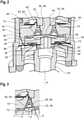
1 eine schematische Schnittansicht eines erfindungsgemäßen Magnetventils; - -
2 einen vergrößerten Ausschnitt der Ansicht nach1 ; - -
3 einen vergrößerten Ausschnitt aus2 ; - -
4 eine schematische Schnittansicht des Ankers und der Lagerfedern des erfindungsgemäßen Magnetventils; und - -
5 eine schematische Explosionsansicht des Ankers und der Lagerfedern des erfindungsgemäßen Magnetventils.
- -
1 a schematic sectional view of a solenoid valve according to the invention; - -
2 an enlarged section of the view1 ; - -
3 an enlarged section2 ; - -
4 a schematic sectional view of the armature and the bearing springs of the solenoid valve according to the invention; and - -
5 a schematic exploded view of the armature and the bearing springs of the solenoid valve according to the invention.
In Axialrichtung A unterhalb des Kerns 18 ist ein axial beweglich gelagerter Anker 20 angeordnet, der ebenfalls Teil des elektromagnetischen Antriebs 14 ist.Arranged in the axial direction A below the
Das Gehäuse 12 ist hier magnetisch leitfähig ausgebildet, sodass es gleichzeitig als Rückschluss für den magnetischen Kreis des elektromagnetischen Antriebs 14 dient.The
In diesem Beispiel ist das Magnetventil 10 als normal geschlossenes Ventil ausgebildet, d.h., solange die Magnetspule 16 nicht bestromt ist, befindet sich der Anker 20 in seiner vom Kern 18 entfernten Position, und das Magnetventil 10 ist geschlossen. Zum Öffnen wird die Magnetspule 16 bestromt und der Anker 20 in Richtung zum Kern 18 gezogen, wodurch das Magnetventil 10 geöffnet wird.In this example, the
An seiner vom Kern 18 abgewandten Seite ist der Anker 20 mit einer Dichtung 22 versehen, die mit einem Ventilsitz 24 an einem Fluideingang 26 zusammenwirkt, wobei die Dichtung 22 dichtend auf dem Ventilsitz 24 aufliegt, wenn das Magnetventil 10 geschlossen ist.On its side facing away from the
Der Anker 20 ist vom Kern 18 durch einen Luftspalt 40 getrennt (siehe
Ein zweiter Luftspalt 42 ist zwischen einem Außenumfang des Ankers 20 und einer Innenwand des Gehäuses 12 gebildet. Dieser Luftspalt 42 ist hier zylindrisch und ändert seine Breite im Wesentlichen nicht, wenn sich der Anker 20 axial verschiebt (siehe
Der Fluideingang 26 ist in diesem Beispiel ringförmig von einem Fluidausgang 28 umgeben (siehe auch
Liegt der Anker 20 auf dem Ventilsitz 24 auf, ist das Magnetventil 10 geschlossen, und eine Fluidströmung vom Fluideingang 26 zum Fluidausgang 28 ist unterbunden.If the
Der Fluideingang 26 sowie der Fluidausgang 28 sind in diesem Beispiel mit Fluidleitungen 32 verbunden, die in einem Fluidblock 30 ausgebildet sind, auf den das Gehäuse 12 gedichtet aufgesetzt ist (siehe
Der Fluideingang 26 ist hier durch ein Rohr 34 gebildet, an dessen einem Ende der Ventilsitz 24 ausgebildet ist und dessen anderes Ende 36 gedichtet in den Fluidblock 30 eingesetzt ist.The
Der ventilsitznahe Teil des Fluidausgang 28 ist genauso wie der ventilsitznahe Teil des Fluideingangs 26 noch innerhalb des Gehäuses 12 angeordnet.The part of the
Eine äußere Umfangswand 38 des Fluidausgangs 28 ist als Strömungsleitfläche ausgebildet und verläuft stetig radial einwärts gekrümmt, sodass die im Wesentlichen radial gerichtete Strömung am Ventilsitz 24 durch eine stetige Krümmung in die Axialrichtung A, also parallel zum Rohr 34, umgelenkt wird.An outer
Innerhalb des Ankers 20 ist eine Druckausgleichskammer 44 ausgebildet, die über einen Druckausgleichskanal 46 in ständiger Strömungsverbindung mit dem Fluideingang 26 steht. Somit überträgt sich der am Fluideingang 26 anstehende Druck auch in die Druckausgleichskammer 44. Neben dem Druckausgleichskanal 46 hat die Druckausgleichskammer 44 keinen Aus- oder Eingang.A
Die Druckausgleichskammer 44 ist zum Kern 18 hin durch eine flexible Membran 48 fluiddicht begrenzt. Somit kann kein Fluid über die Druckausgleichskammer 44 in andere Bereiche des Gehäuses 12 gelangen.The
Im Zentrum 50 der Membran 48 ist eine Abstützfläche 52 vorgesehen, die im Wesentlichen flach ist (siehe
Das Stützbauteil 54 ist fest mit dem Kern 18 verbunden und wie dieser im Gehäuse 12 feststehend angeordnet. Im Gegensatz zum Kern 18 besteht das Stützbauteil 54 jedoch aus einem magnetisch nicht leitfähigen Material.The
In diesem Beispiel liegt die Membran 48 sowohl im geschlossenen als auch im geöffneten Zustand des Magnetventils 10 mit ihrer Abstützfläche 52 an der Auflagefläche 56 an, bleibt also bei einer Bewegung des Ankers 20 im Zentrum 50 im Wesentlichen ortsfest. Die aufgrund des in der Druckausgleichskammer 44 durch den dort herrschenden Druck auf die Membran 48 erzeugte Kraft wird somit stets über das Stützbauteil 54 und den Kern 18 in das Gehäuse 12 eingeleitet. Die Fluidkräfte auf den Anker 20 heben sich im Wesentlichen auf. Einerseits drückt der Fluiddruck auf die vom Ventilsitz 24 umschlossene Fläche des Ankers 20 den Anker 20 in Richtung Kern 18. Andererseits wirkt über annähernd denselben Flächeninhalt der Fluiddruck in der Druckausgleichskammer 44 über die Abstützfläche 52 der Membran 48 auf die Auflagefläche 56 am Stützbauteil 54. Der Anker 20 ist somit druckausgeglichen und das Magnetventil 10 druckentlastet.In this example, the
Die vom Ventilsitz 24 umschlossene Fläche des Fluideingangs 26 ist hier geringfügig größer gewählt als die Abstützfläche 52 im Zentrum 50 der Membran 48.The area of the
Die Membran 48 ist mit ihrem Umfangsrand 58, der insbesondere einen runden Außenumfang 58 beschreibt, fest am Anker 20 fixiert. Der Umfangsrand 58 der Membran 48 bewegt sich daher zusammen mit dem Anker 20 in Axialrichtung A beim Öffnen und Schließen des Magnetventils 10, während das Zentrum 50 der Membran 48 am Stützbauteil 54 verbleibt. Das Zentrum 50 der Membran 48 liegt nicht am Anker 20 an.The
Die Abstützfläche 52 der Membran 48 ist von einer hier ringförmigen Vorwölbung 60 umgeben, die gegenüber der Abstützfläche 52 und gegenüber dem Umfangsrand 58 in Richtung zum Kern 18 erhaben ist. Die Auflagefläche 56 liegt innerhalb der von der Vorwölbung 60 umschlossenen Fläche.The support surface 52 of the
Ein äußerer Umfangsrand 62 der Vorwölbung 60 ist in seiner Neigung an die Neigung einer Anlagefläche 64 am Anker 20 angeglichen, sodass zumindest im geschlossenen Zustand des Magnetventils 10 die Anlagefläche 64 am äußeren Umfangsrand 62 anliegt. Entsprechend ist ein innerer Umfangsrand 66 der Vorwölbung 60 in seiner Neigung an eine Anlagefläche 68 am Stützbauteil 54 angeglichen, die die Auflagefläche 56 ringförmig umgibt und an der der innere Umfangsrand 66 der Membran 48 zumindest im geöffneten Zustand des Magnetventils 10 anliegt. Aufgrund der angepassten Neigungen rollt die Membran 48 am Anker 20 sowie am Stützbauteil 54 ab, wenn sich der Anker 20 zwischen der geschlossenen und der geöffneten Stellung des Magnetventils 10 bewegt.The inclination of an outer
Ein Winkel α zwischen der Anlagefläche 64 am Anker 20 und der Axialrichtung A kann zwischen 5° und 85°, insbesondere zwischen 15° und 25° gewählt sein. Ein Winkel β zwischen der Anlagefläche 68 am Stützbauteil 54 und der Axialrichtung A kann im selben Bereich liegen und kann insbesondere gleich dem Winkel α gewählt sein. Diese Geometrie ist in
Sämtliche Kanten im Bereich der Anlageflächen 64, 68, mit denen die Membran 48 in Berührung kommt, sind mit einem großen Radius abgerundet, um einen Verschleiß der Membran 48 zu minimieren.All edges in the area of the contact surfaces 64, 68 with which the
Der Anker 20 ist in diesem Beispiel mehrteilig aufgebaut und umfasst ein magnetisch leitfähiges Oberteil 70, das auf der Seite des elektromagnetischen Antriebs 14 angeordnet ist, sowie ein Unterteil 72, das auf der zum Fluidblock 30 gerichteten Seite liegt. Der Umfangsrand 58 der Membran 48 ist hier durch Klemmen zwischen dem Oberteil 70 und dem Unterteil 72 befestigt.The
Eine zusätzliche Strukturierung 74 im Unterteil 72 und/oder im Oberteil 70, die in Radialrichtung r zwischen dem Umfangsrand 58 und der Vorwölbung 60 liegt, kann optional vorgesehen sein, um die Membran 48 zusätzlich zu sichern.An additional structuring 74 in the
Das Unterteil 72 weist eine Öffnung 76 auf, in die eine Hülse 78 eingesetzt ist, die auf geeignete Weise am Unterteil 72 fest fixiert ist. In dieser Hülse 78 ist der Druckausgleichskanal 46 vorgesehen. Die Druckausgleichskammer 44 ist somit von der Membran 48, dem Unterteil 72 sowie der Hülse 78 begrenzt.The
An einem zum Fluideingang 26 gerichteten Ende 80 der Hülse 78 ist die umlaufende Dichtung 22 angeordnet, die bei geschlossenem Magnetventil 10 auf dem Ventilsitz 24 aufliegt und so den Fluideingang 26 verschließt.The
Der Anker 20 ist über zwei Lagerfedern 84, 86 im Gehäuse 12 befestigt. Beide Lagerfedern 84, 86 sind hier durch Formfedern realisiert, wobei jeweils zwei übereinanderliegende Formfedern eine Lagerfeder 84, 86 bilden, wie in
Die Formfedern der Lagerfedern 84 und 86 unterscheiden sich hier in ihrer Form. Die fluideingangsseitigen Formfedern, die die Lagerfeder 86 bilden, weisen eine mittige Durchgangsöffnung 88 auf, deren Rand zwischen einer Unterseite des Unterteils 72 und einer Schulter 90 der Hülse 78 geklemmt ist, wodurch der Anker 20 an der Lagerfedern 86 fixiert ist.The shaped springs of the bearing springs 84 and 86 differ here in their shape. The shaped springs on the fluid inlet side, which form the bearing
An der kernseitigen Lagerfedern 84 ist der Anker 20 in diesem Beispiel durch die Anlage einer am Oberteil 70 ausgebildeten Schulter 92 an radial inneren Vorsprüngen 94 der Formfedern gehalten.In this example, the
An ihren radialen Außenumfängen sind die Lagerfedern 84, 86 jeweils auf geeignete Weise fest mit der Innenseite des Gehäuses verbunden. Beide Lagerfedern 84, 86 sind daher an ihrem Außenumfang axial unverschieblich im Gehäuse 12 gehalten, können sich aber in ihrem Zentrum flexibel entlang der Axialrichtung A bewegen, sodass sich der Anker 20 entlang der Axialrichtung A verschieben kann. In Radialrichtung r sind hingegen sämtliche Formfedern so steif ausgebildet, dass der Anker 20 keinen Bewegungsspielraum in Radialrichtung r hat, sodass die Luftspalte 40, 42 schmal gehalten werden können.At their radial outer circumferences, the bearing springs 84, 86 are each fixedly connected to the inside of the housing in a suitable manner. Both bearing springs 84, 86 are therefore held axially immovably in the
Die beiden Lagerfedern 84, 86 sind in Axialrichtung A betrachtet auf beiden Seiten des Ankers 20 in einem möglichst großen axialen Abstand angeordnet, was ein Verkippen des Ankers 20 in Bezug auf die Axialrichtung A verhindert.Viewed in the axial direction A, the two bearing springs 84, 86 are arranged on both sides of the
Die beiden Formfedern, die die fluideingangsseitige Lagerfeder 86 bilden, sind hier gleich geformt, wobei eine der Formfedern um 180° senkrecht zur Axialrichtung A gegenüber der anderen Formfeder gedreht angeordnet ist. Im Ermessen des Fachmanns kann natürlich für die Formfedern jede geeignete Form gewählt werden.The two shaped springs that form the bearing
Claims (16)
Translated fromGermanPriority Applications (3)
| Application Number | Priority Date | Filing Date | Title |
|---|---|---|---|
| DE102018105348.7ADE102018105348B4 (en) | 2018-03-08 | 2018-03-08 | magnetic valve |
| US16/296,537US10865907B2 (en) | 2018-03-08 | 2019-03-08 | Solenoid valve |
| CN201910175338.3ACN110242785B (en) | 2018-03-08 | 2019-03-08 | Electromagnetic valve |
Applications Claiming Priority (1)
| Application Number | Priority Date | Filing Date | Title |
|---|---|---|---|
| DE102018105348.7ADE102018105348B4 (en) | 2018-03-08 | 2018-03-08 | magnetic valve |
Publications (2)
| Publication Number | Publication Date |
|---|---|
| DE102018105348A1 DE102018105348A1 (en) | 2019-09-12 |
| DE102018105348B4true DE102018105348B4 (en) | 2022-02-24 |
Family
ID=67701260
Family Applications (1)
| Application Number | Title | Priority Date | Filing Date |
|---|---|---|---|
| DE102018105348.7AActiveDE102018105348B4 (en) | 2018-03-08 | 2018-03-08 | magnetic valve |
Country Status (3)
| Country | Link |
|---|---|
| US (1) | US10865907B2 (en) |
| CN (1) | CN110242785B (en) |
| DE (1) | DE102018105348B4 (en) |
Families Citing this family (7)
| Publication number | Priority date | Publication date | Assignee | Title |
|---|---|---|---|---|
| US10544876B2 (en)* | 2018-04-18 | 2020-01-28 | Chin-Yuan Chen | Solenoid valve for irrigation systems |
| US11524886B2 (en) | 2021-02-05 | 2022-12-13 | Cana Technology, Inc. | Ingredients cartridge for a beverage mixture dispensing system |
| CN113140426B (en)* | 2021-04-13 | 2023-08-08 | 西安航天动力研究所 | Mechanical pressure switch capable of realizing high-precision rigidity compensation and compensation method thereof |
| EP4174350A1 (en)* | 2021-10-27 | 2023-05-03 | Fas Medic S.A. | Valve assembly and method |
| DE102022110949A1 (en)* | 2022-05-04 | 2023-11-09 | Festo Se & Co. Kg | Valve for controlling the flow of a fluid |
| US20240282385A1 (en)* | 2023-02-20 | 2024-08-22 | Micron Technology, Inc. | On-die capacitor banks |
| CN118623006A (en)* | 2024-08-05 | 2024-09-10 | 河南航天液压气动技术有限公司 | A design of armature suspension guide |
Citations (3)
| Publication number | Priority date | Publication date | Assignee | Title |
|---|---|---|---|---|
| US20040113113A1 (en) | 2001-12-18 | 2004-06-17 | Erwin Krimmer | ELectromagnetic valve |
| EP1970610A1 (en) | 2007-03-14 | 2008-09-17 | Asco Joucomatic GmbH | Device for regulating a fluid or gaseous medium |
| US20140326909A1 (en) | 2013-05-01 | 2014-11-06 | Mks Instruments, Inc. | Pressure-balanced control valves |
Family Cites Families (11)
| Publication number | Priority date | Publication date | Assignee | Title |
|---|---|---|---|---|
| GB905024A (en) | 1958-10-27 | 1962-09-05 | Secr Aviation | Improvements in or relating to fluid pressure valves |
| US4231548A (en) | 1978-08-02 | 1980-11-04 | Braukmann Armaturen Ag | Balance valve disc and seat structure |
| US4522371A (en)* | 1983-06-20 | 1985-06-11 | Borg-Warner Corporation | Proportional solenoid valve |
| JPH0738778Y2 (en)* | 1987-12-18 | 1995-09-06 | アイシン精機株式会社 | Solenoid valve device |
| GB9322850D0 (en) | 1993-11-05 | 1993-12-22 | Lucas Ind Plc | Control valve |
| US6505812B1 (en)* | 2000-11-17 | 2003-01-14 | Mks Instruments, Inc. | Solenoid valve |
| JP3625456B2 (en) | 2002-07-16 | 2005-03-02 | 三菱電機株式会社 | Valve timing control device for internal combustion engine |
| US7987272B2 (en) | 2004-12-06 | 2011-07-26 | Cisco Technology, Inc. | Performing message payload processing functions in a network element on behalf of an application |
| US8127791B2 (en)* | 2005-12-21 | 2012-03-06 | Saturn Electronics & Engineering, Inc. | Solenoid operated fluid control valve |
| CN201396474Y (en)* | 2009-05-10 | 2010-02-03 | 方云 | Normal-closed electromagnetic valve |
| DE102014003381A1 (en)* | 2014-03-06 | 2015-09-10 | Wabco Gmbh | magnetic valve |
- 2018
- 2018-03-08DEDE102018105348.7Apatent/DE102018105348B4/enactiveActive
- 2019
- 2019-03-08USUS16/296,537patent/US10865907B2/enactiveActive
- 2019-03-08CNCN201910175338.3Apatent/CN110242785B/enactiveActive
Patent Citations (3)
| Publication number | Priority date | Publication date | Assignee | Title |
|---|---|---|---|---|
| US20040113113A1 (en) | 2001-12-18 | 2004-06-17 | Erwin Krimmer | ELectromagnetic valve |
| EP1970610A1 (en) | 2007-03-14 | 2008-09-17 | Asco Joucomatic GmbH | Device for regulating a fluid or gaseous medium |
| US20140326909A1 (en) | 2013-05-01 | 2014-11-06 | Mks Instruments, Inc. | Pressure-balanced control valves |
Also Published As
| Publication number | Publication date |
|---|---|
| US20190277422A1 (en) | 2019-09-12 |
| CN110242785B (en) | 2022-10-21 |
| CN110242785A (en) | 2019-09-17 |
| US10865907B2 (en) | 2020-12-15 |
| DE102018105348A1 (en) | 2019-09-12 |
Similar Documents
| Publication | Publication Date | Title |
|---|---|---|
| DE102018105348B4 (en) | magnetic valve | |
| DE19826076C1 (en) | Double safety valve for the gas inlet to a gas heating system | |
| EP3263962B1 (en) | Valve | |
| DE2757803A1 (en) | MAGNETIC VALVE | |
| EP2246601B1 (en) | Electromagnetic hydraulic valve | |
| DE2737675B2 (en) | Electromagnetically operated directional valve for a servomotor, reversible with pressurized fluid | |
| WO2016015932A1 (en) | Adjustable damping valve device | |
| EP2700850A2 (en) | Double seat valve with reliable closing function | |
| WO2003074912A1 (en) | Combined check/ pressure control valve | |
| EP3724542A1 (en) | Valve | |
| DE2928611A1 (en) | ADJUSTABLE ELECTROMAGNET VALVE | |
| DE2743829A1 (en) | MULTI-WAY VALVE | |
| DE102010044442B4 (en) | Electromagnet valve device with two working connections | |
| AT398114B (en) | PROPORTIONAL 2-WAY VALVE | |
| DE102018114238B4 (en) | Controlled brake solenoid valve | |
| DE2750631C2 (en) | Valve | |
| DE102019135454B3 (en) | Proportional valve and flow control unit | |
| DE8533506U1 (en) | Poppet valve | |
| EP3686465B1 (en) | Quick switch valve | |
| DE4022395C2 (en) | Proportional solenoid valve and method for assembling such a proportional solenoid valve | |
| DE4221821A1 (en) | Electromagnetically-operated valve for automobile - has magnetic armature contained in oil-filled armature space sealed by two rubber membranes | |
| DE102015223894A1 (en) | Pressure relieved valve | |
| EP2338750B1 (en) | Magnetic valve and driver assistance device | |
| EP3643954A1 (en) | Electromagnetic valve, method for operating an electromagnetic valve | |
| DE19605895C2 (en) | Throttle device compensated for pressure force |
Legal Events
| Date | Code | Title | Description |
|---|---|---|---|
| R163 | Identified publications notified | ||
| R012 | Request for examination validly filed | ||
| R018 | Grant decision by examination section/examining division | ||
| R020 | Patent grant now final |