DE102018105158A1 - GEERDETER REFLECTOR FOR A VEHICLE LIGHTS FIXING WITH A CAPACITIVE SWITCH - Google Patents
GEERDETER REFLECTOR FOR A VEHICLE LIGHTS FIXING WITH A CAPACITIVE SWITCHDownload PDFInfo
- Publication number
- DE102018105158A1 DE102018105158A1DE102018105158.1ADE102018105158ADE102018105158A1DE 102018105158 A1DE102018105158 A1DE 102018105158A1DE 102018105158 ADE102018105158 ADE 102018105158ADE 102018105158 A1DE102018105158 A1DE 102018105158A1
- Authority
- DE
- Germany
- Prior art keywords
- vehicle
- reflector
- conductive thermoplastic
- thermoplastic layer
- metal layer
- Prior art date
- Legal status (The legal status is an assumption and is not a legal conclusion. Google has not performed a legal analysis and makes no representation as to the accuracy of the status listed.)
- Withdrawn
Links
Images


Classifications
- F—MECHANICAL ENGINEERING; LIGHTING; HEATING; WEAPONS; BLASTING
- F21—LIGHTING
- F21V—FUNCTIONAL FEATURES OR DETAILS OF LIGHTING DEVICES OR SYSTEMS THEREOF; STRUCTURAL COMBINATIONS OF LIGHTING DEVICES WITH OTHER ARTICLES, NOT OTHERWISE PROVIDED FOR
- F21V23/00—Arrangement of electric circuit elements in or on lighting devices
- F21V23/04—Arrangement of electric circuit elements in or on lighting devices the elements being switches
- F21V23/0442—Arrangement of electric circuit elements in or on lighting devices the elements being switches activated by means of a sensor, e.g. motion or photodetectors
- F21V23/0485—Arrangement of electric circuit elements in or on lighting devices the elements being switches activated by means of a sensor, e.g. motion or photodetectors the sensor sensing the physical interaction between a user and certain areas located on the lighting device, e.g. a touch sensor
- B—PERFORMING OPERATIONS; TRANSPORTING
- B60—VEHICLES IN GENERAL
- B60Q—ARRANGEMENT OF SIGNALLING OR LIGHTING DEVICES, THE MOUNTING OR SUPPORTING THEREOF OR CIRCUITS THEREFOR, FOR VEHICLES IN GENERAL
- B60Q3/00—Arrangement of lighting devices for vehicle interiors; Lighting devices specially adapted for vehicle interiors
- B60Q3/60—Arrangement of lighting devices for vehicle interiors; Lighting devices specially adapted for vehicle interiors characterised by optical aspects
- B—PERFORMING OPERATIONS; TRANSPORTING
- B60—VEHICLES IN GENERAL
- B60Q—ARRANGEMENT OF SIGNALLING OR LIGHTING DEVICES, THE MOUNTING OR SUPPORTING THEREOF OR CIRCUITS THEREFOR, FOR VEHICLES IN GENERAL
- B60Q3/00—Arrangement of lighting devices for vehicle interiors; Lighting devices specially adapted for vehicle interiors
- B60Q3/70—Arrangement of lighting devices for vehicle interiors; Lighting devices specially adapted for vehicle interiors characterised by the purpose
- B60Q3/74—Arrangement of lighting devices for vehicle interiors; Lighting devices specially adapted for vehicle interiors characterised by the purpose for overall compartment lighting; for overall compartment lighting in combination with specific lighting, e.g. room lamps with reading lamps
- B—PERFORMING OPERATIONS; TRANSPORTING
- B60—VEHICLES IN GENERAL
- B60Q—ARRANGEMENT OF SIGNALLING OR LIGHTING DEVICES, THE MOUNTING OR SUPPORTING THEREOF OR CIRCUITS THEREFOR, FOR VEHICLES IN GENERAL
- B60Q3/00—Arrangement of lighting devices for vehicle interiors; Lighting devices specially adapted for vehicle interiors
- B60Q3/50—Mounting arrangements
- B60Q3/51—Mounting arrangements for mounting lighting devices onto vehicle interior, e.g. onto ceiling or floor
- B—PERFORMING OPERATIONS; TRANSPORTING
- B60—VEHICLES IN GENERAL
- B60Q—ARRANGEMENT OF SIGNALLING OR LIGHTING DEVICES, THE MOUNTING OR SUPPORTING THEREOF OR CIRCUITS THEREFOR, FOR VEHICLES IN GENERAL
- B60Q3/00—Arrangement of lighting devices for vehicle interiors; Lighting devices specially adapted for vehicle interiors
- B60Q3/80—Circuits; Control arrangements
- B60Q3/82—Switches specially adapted for vehicle interior lighting, e.g. switching by tilting the lens
- F—MECHANICAL ENGINEERING; LIGHTING; HEATING; WEAPONS; BLASTING
- F21—LIGHTING
- F21V—FUNCTIONAL FEATURES OR DETAILS OF LIGHTING DEVICES OR SYSTEMS THEREOF; STRUCTURAL COMBINATIONS OF LIGHTING DEVICES WITH OTHER ARTICLES, NOT OTHERWISE PROVIDED FOR
- F21V23/00—Arrangement of electric circuit elements in or on lighting devices
- F21V23/001—Arrangement of electric circuit elements in or on lighting devices the elements being electrical wires or cables
- F—MECHANICAL ENGINEERING; LIGHTING; HEATING; WEAPONS; BLASTING
- F21—LIGHTING
- F21V—FUNCTIONAL FEATURES OR DETAILS OF LIGHTING DEVICES OR SYSTEMS THEREOF; STRUCTURAL COMBINATIONS OF LIGHTING DEVICES WITH OTHER ARTICLES, NOT OTHERWISE PROVIDED FOR
- F21V23/00—Arrangement of electric circuit elements in or on lighting devices
- F21V23/06—Arrangement of electric circuit elements in or on lighting devices the elements being coupling devices, e.g. connectors
- H—ELECTRICITY
- H03—ELECTRONIC CIRCUITRY
- H03K—PULSE TECHNIQUE
- H03K17/00—Electronic switching or gating, i.e. not by contact-making and –breaking
- H03K17/94—Electronic switching or gating, i.e. not by contact-making and –breaking characterised by the way in which the control signals are generated
- H03K17/945—Proximity switches
- H03K17/955—Proximity switches using a capacitive detector
- H—ELECTRICITY
- H03—ELECTRONIC CIRCUITRY
- H03K—PULSE TECHNIQUE
- H03K17/00—Electronic switching or gating, i.e. not by contact-making and –breaking
- H03K17/94—Electronic switching or gating, i.e. not by contact-making and –breaking characterised by the way in which the control signals are generated
- H03K17/96—Touch switches
- H03K17/962—Capacitive touch switches
- H—ELECTRICITY
- H05—ELECTRIC TECHNIQUES NOT OTHERWISE PROVIDED FOR
- H05B—ELECTRIC HEATING; ELECTRIC LIGHT SOURCES NOT OTHERWISE PROVIDED FOR; CIRCUIT ARRANGEMENTS FOR ELECTRIC LIGHT SOURCES, IN GENERAL
- H05B45/00—Circuit arrangements for operating light-emitting diodes [LED]
- H05B45/10—Controlling the intensity of the light
- H—ELECTRICITY
- H05—ELECTRIC TECHNIQUES NOT OTHERWISE PROVIDED FOR
- H05B—ELECTRIC HEATING; ELECTRIC LIGHT SOURCES NOT OTHERWISE PROVIDED FOR; CIRCUIT ARRANGEMENTS FOR ELECTRIC LIGHT SOURCES, IN GENERAL
- H05B45/00—Circuit arrangements for operating light-emitting diodes [LED]
- H05B45/30—Driver circuits
- H05B45/37—Converter circuits
- F—MECHANICAL ENGINEERING; LIGHTING; HEATING; WEAPONS; BLASTING
- F21—LIGHTING
- F21W—INDEXING SCHEME ASSOCIATED WITH SUBCLASSES F21K, F21L, F21S and F21V, RELATING TO USES OR APPLICATIONS OF LIGHTING DEVICES OR SYSTEMS
- F21W2106/00—Interior vehicle lighting devices
- F—MECHANICAL ENGINEERING; LIGHTING; HEATING; WEAPONS; BLASTING
- F21—LIGHTING
- F21W—INDEXING SCHEME ASSOCIATED WITH SUBCLASSES F21K, F21L, F21S and F21V, RELATING TO USES OR APPLICATIONS OF LIGHTING DEVICES OR SYSTEMS
- F21W2107/00—Use or application of lighting devices on or in particular types of vehicles
- F21W2107/10—Use or application of lighting devices on or in particular types of vehicles for land vehicles
- H—ELECTRICITY
- H03—ELECTRONIC CIRCUITRY
- H03K—PULSE TECHNIQUE
- H03K2217/00—Indexing scheme related to electronic switching or gating, i.e. not by contact-making or -breaking covered by H03K17/00
- H03K2217/94—Indexing scheme related to electronic switching or gating, i.e. not by contact-making or -breaking covered by H03K17/00 characterised by the way in which the control signal is generated
- H03K2217/96—Touch switches
- H03K2217/9607—Capacitive touch switches
- H03K2217/960755—Constructional details of capacitive touch and proximity switches
- H—ELECTRICITY
- H03—ELECTRONIC CIRCUITRY
- H03K—PULSE TECHNIQUE
- H03K2217/00—Indexing scheme related to electronic switching or gating, i.e. not by contact-making or -breaking covered by H03K17/00
- H03K2217/94—Indexing scheme related to electronic switching or gating, i.e. not by contact-making or -breaking covered by H03K17/00 characterised by the way in which the control signal is generated
- H03K2217/96—Touch switches
- H03K2217/9607—Capacitive touch switches
- H03K2217/960785—Capacitive touch switches with illumination
Landscapes
- Engineering & Computer Science (AREA)
- Mechanical Engineering (AREA)
- General Engineering & Computer Science (AREA)
- Human Computer Interaction (AREA)
- Non-Portable Lighting Devices Or Systems Thereof (AREA)
- Arrangements Of Lighting Devices For Vehicle Interiors, Mounting And Supporting Thereof, Circuits Therefore (AREA)
Abstract
Translated fromGermanDescription
Translated fromGermanTECHNISCHES GEBIETTECHNICAL AREA
Die vorliegende Offenbarung betrifft im Allgemeinen Beleuchtungsbefestigungen für Fahrzeuge und insbesondere einen geerdeten Reflektor für eine Fahrzeugbeleuchtungsbefestigung mit einem kapazitiven Schalter.The present disclosure relates generally to lighting fixtures for vehicles, and more particularly to a grounded reflector for vehicle lighting fixture having a capacitive switch.
ALLGEMEINER STAND DER TECHNIKGENERAL PRIOR ART
Fahrzeughersteller gehen zunehmend von physischen Knöpfen zu Touchscreens und kapazitiven Schaltern über. Metall kann in der Nähe dieser Schnittstellen Streukapazität hervorrufen, welche die Fähigkeit dieser Schnittstellen beeinflusst, Eingaben zu erfassen, es sei denn, dass das Metall geerdet ist. Häufig konstruieren Fahrzeughersteller Teile, um Metall aus der Nähe dieser Schnittstellen zu entfernen. Dies kann jedoch die Ästhetik und Nutzbarkeit anderer Teile der Fahrzeuge, wie etwa eines Reflektors für eine Fahrzeugbeleuchtungsbefestigung, beeinträchtigen.Vehicle manufacturers are increasingly transitioning from physical buttons to touchscreens and capacitive switches. Metal can cause stray capacitance near these interfaces, which affects the ability of these interfaces to detect inputs, unless the metal is grounded. Often vehicle manufacturers construct parts to remove metal from near these interfaces. However, this may affect the aesthetics and usability of other parts of the vehicles, such as a vehicle lighting fixture reflector.
KURZDARSTELLUNGSUMMARY
Die beigefügten Patentansprüche definieren diese Patentanmeldung. Die vorliegende Offenbarung fasst Aspekte der Ausführungsformen zusammen und sollte nicht zum Einschränken der Patentansprüche verwendet werden. Andere Umsetzungen werden gemäß den hierin beschriebenen Techniken in Betracht gezogen, wie dem Durchschnittsfachmann bei der Durchsicht der folgenden Zeichnungen und detaillierten Beschreibung ersichtlich wird, und diese Umsetzungen sollen innerhalb des Schutzumfangs dieser Anmeldung liegen.The appended claims define this patent application. The present disclosure summarizes aspects of the embodiments and should not be used to limit the claims. Other implementations are contemplated in accordance with the techniques described herein, as will be apparent to one of ordinary skill in the art upon review of the following drawings and detailed description, and these implementations are intended to be within the scope of this application.
Es werden beispielhafte Ausführungsformen für einen geerdeten Reflektor für eine Fahrzeugbeleuchtungsbefestigung mit einem kapazitiven Schalter offenbart. Ein beispielhaft offenbarte Leuchtenbaugruppe für ein Fahrzeug beinhaltet eine Leuchtenbaugruppe, einen geerdeten Reflektor und einen kapazitiven Schalter. Der geerdete Reflektor weist eine Metallschicht auf, die an eine Massefläche des Fahrzeugs gekoppelt ist. Die Metallschicht ist jedoch nicht direkt an die Massefläche des Fahrzeugs gekoppelt. Der kapazitive Schalter ist elektrisch an die Leuchtenbaugruppe gekoppelt, um die Leuchtenbaugruppe auf Grundlage des Erfassens eines kapazitiven Objekts innerhalb eines Erfassungsfelds zu steuern.Exemplary embodiments for a grounded reflector for a vehicle lighting fixture with a capacitive switch are disclosed. An exemplary light assembly for a vehicle includes a light assembly, a grounded reflector, and a capacitive switch. The grounded reflector has a metal layer coupled to a ground plane of the vehicle. However, the metal layer is not directly coupled to the ground plane of the vehicle. The capacitive switch is electrically coupled to the light assembly for controlling the light assembly based on detecting a capacitive object within a detection field.
Ein beispielhaft offenbarter Reflektor für eine Fahrzeugbeleuchtungsbefestigung beinhaltet eine leitfähige thermoplastische Schicht, eine Metallschicht und Erdungsstifte. Die Metallschicht bedeckt eine konkave Fläche der thermoplastischen Schicht. Die Erdungsstifte sind in die leitfähige thermoplastische Schicht eingebettet. Zusätzlich stehen die Erdungsstifte nicht in direktem Kontakt mit der Metallschicht.An exemplary disclosed reflector for vehicle lighting fixture includes a conductive thermoplastic layer, a metal layer and grounding pins. The metal layer covers a concave surface of the thermoplastic layer. The grounding pins are embedded in the conductive thermoplastic layer. In addition, the grounding pins are not in direct contact with the metal layer.
Figurenlistelist of figures
Zum besseren Verständnis der Erfindung kann auf Ausführungsformen Bezug genommen werden, die in den folgenden Zeichnungen gezeigt sind. Die Komponenten in den Zeichnungen sind nicht zwingend maßstabsgetreu und zugehörige Elemente können weggelassen sein oder in einigen Fällen können Proportionen vergrößert dargestellt sein, um die hierin beschriebenen neuartigen Merkmale hervorzuheben und eindeutig zu veranschaulichen. Außerdem können Systemkomponenten, wie auf dem Fachgebiet bekannt, verschiedenartig angeordnet sein. Ferner sind in den Zeichnungen sich entsprechende Teile in den verschiedenen Ansichten durch gleiche Bezugszeichen gekennzeichnet.
1 veranschaulicht ein Fahrzeug mit einer Beleuchtungsbefestigung, die einen kapazitiven Schalter gemäß den Lehren dieser Offenbarung beinhaltet.- Die
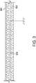
2A und2B veranschaulichen die Beleuchtungsbefestigung aus1 mit einem geerdeten Reflektor. 3 veranschaulicht eine Querschnittsansicht des geerdeten Reflektors der2A und2B .
1 FIG. 10 illustrates a vehicle with a lighting fixture including a capacitive switch in accordance with the teachings of this disclosure. FIG.- The
2A and2 B illustrate the lighting fixture1 with a grounded reflector. 3 FIG. 12 illustrates a cross-sectional view of the grounded reflector of FIG2A and2 B ,
DETAILLIERTE BESCHREIBUNG VON AUSFÜHRUNGSBEISPIELENDETAILED DESCRIPTION OF EMBODIMENTS
Wenngleich die Erfindung in unterschiedlichen Formen ausgeführt werden kann, werden in den Zeichnungen einige beispielhafte und nicht einschränkende Ausführungsformen gezeigt und nachfolgend beschrieben, wobei es sich versteht, dass die vorliegende Offenbarung als Erläuterung der Erfindung anhand von Beispielen anzusehen ist und damit nicht beabsichtigt wird, die Erfindung auf die konkreten dargestellten Ausführungsformen zu beschränken.While the invention may be embodied in various forms, some exemplary and non-limiting embodiments are shown in the drawings and described below, it being understood that the present disclosure should be considered illustrative of the invention and is not intended to be exhaustive To limit the invention to the specific embodiments shown.
Beleuchtungsbefestigungen (z. B. Überkopfkonsolenleuchten, Deckenleuchten usw.), die kapazitive Schalter beinhalten, werden durch Erfassen einer Änderung in der Kapazität innerhalb eines Erfassungsfelds des kapazitiven Schalters eingeschaltet, die durch ein kapazitives Objekt, wie etwa eine menschliche Hand, verursacht wird. Zum Beispiel kann die Beleuchtungsbefestigung eingeschaltet und ausgeschaltet werden, wenn eine Person eine Linse der Beleuchtungsbefestigung oder den Kunststoff um die Beleuchtungsbefestigung berührt. Diese Beleuchtungsbefestigungen beinhalten eine Linse, eine Lichtquelle (z. B. eine oder mehrere lichtemittierende Dioden (LEDs) usw.) und einen Reflektor. Der Reflektor beinhaltet eine Metallfläche, um das von der Beleuchtungsbefestigung erzeugte Licht zu erhöhen. Da sich jedoch das Metall nahe des kapazitiven Schalters (z. B. 10 bis 15 Millimeter (mm) usw.) befindet, erzeugt der kapazitive Schalter eine Streukapazität, verdeckte Schalter und/oder elektromagnetische Interferenzprobleme, wenn das Erfassungsfeld vom Schalter abstrahlt.Lighting fixtures (e.g., overhead console lights, ceiling lights, etc.) incorporating capacitive switches are turned on by detecting a change in capacitance within a sensing field of the capacitive switch caused by a capacitive object, such as a human hand. For example, the lighting fixture may be turned on and off when a person touches a lens of the lighting fixture or the plastic around the fixture. These lighting fixtures include a lens, a light source (eg, one or more light emitting diodes (LEDs), etc.) and a reflector. The reflector includes a metal surface to increase the light generated by the lighting fixture. However, because the metal is near the capacitive switch (eg, 10 to 15 millimeters (mm), etc.), the capacitive switch creates stray capacitance, covert switches, and / or electromagnetic interference problems as the detection field radiates from the switch.
Herkömmlicherweise wird das Erden der Metallfläche dadurch versucht, dass (a) ein Draht an die Metallfläche gelötet wird oder ein Krampenstecker verwendet wird, um den Draht an der Metallfläche anzubringen und dann den Draht an der Masse anzubringen oder (b) beide Seiten des Reflektorgehäuses aufgedampft werden und ein Erdungsmetallkontakt mit der metallischen Fläche erzeugt wird. Diese Verfahren sind nicht widerstandsfähig, da sie schwer in der Fertigung einzubauen sind und im Laufe der Zeit ausfallen können, da die Verbindungen entweder brechen oder deren Widerstand erhöht wird. Zusätzlich kann Goldbeschichtung verwendet werden, um eine langfristige Verbindung mit niedrigem Widerstand sicherzustellen. Dies erhöht die Kosten weiter.Conventionally, grounding of the metal surface is attempted by (a) soldering a wire to the metal surface or using a staple plug to attach the wire to the metal surface and then attach the wire to the ground or (b) vapor deposited on both sides of the reflector housing and a grounding metal contact is created with the metallic surface. These methods are not robust because they are difficult to incorporate in manufacturing and may fail over time as the joints either break or increase in resistance. In addition, gold plating can be used to ensure a long-term low resistance connection. This further increases the costs.
Wie nachfolgend offenbart, wird das Reflektorgehäuse aus einem Material geformt, das elektrisch leitfähig ist. In einigen Beispielen weist das Material (a) eine relativ geringe spezifische Dichte auf, um Wärme abzuleiten, (b) weist einen Schmelzpunkt über 210 Grad Celsius (C) auf, ist formstabil, (d) weist einen relativ hohen Betriebstemperaturbereich, (e) relativ geringe Kosten, (f) ein thermoplastisches Material auf, das in komplexe Formen präzisionsgeformt werden kann, und (g) wiederverwertbar ist. Erdungsdraht/Erdungsdrähte und/oder -stifte werden in das Reflektorgehäuse geformt und an einem konvexen Abschnitt des Reflektorgehäuses freigelegt. Wenn sie in ein Fahrzeug eingebaut sind, ist/sind der/die Erdungsdraht/Erdungsdrähte und/oder -stifte mit der Masse verbunden. Das Reflektorgehäuse ist an einem konkaven Abschnitt des Reflektorgehäuses metallisiert. In einigen Beispielen wird eine Metallschicht auf den konkaven Abschnitt des Reflektorgehäuses unter Verwendung eines Aufdampfungsprozesses aufgetragen. Der geerdete Reflektor erleichtert das Anordnen kapazitiver Schalter neben metallischen Flächen ohne Streukapazität, verdeckte Schalter und/oder elektromagnetische Interferenzprobleme. Zusätzlich erleichtert das Formen des/der Erdungsdrähte und/oder -stifte, die in das leitfähige thermoplastische Gehäuse des Reflektors geformt wurden, eine elektrisch und mechanisch widerstandsfähige Verbindung zwischen dem Gehäuse und der Masse des Fahrzeugs.As disclosed below, the reflector housing is formed of a material that is electrically conductive. In some examples, material (a) has a relatively low specific gravity to dissipate heat, (b) has a melting point above 210 degrees Celsius (C), is dimensionally stable, (d) has a relatively high operating temperature range, (e) relatively low cost, (f) a thermoplastic material that can be precision formed into complex shapes, and (g) is recyclable. Ground wire / ground wires and / or pins are molded into the reflector housing and exposed at a convex portion of the reflector housing. When installed in a vehicle, the ground wire (s) and / or pins (s) are / are connected to ground. The reflector housing is metallized on a concave portion of the reflector housing. In some examples, a metal layer is applied to the concave portion of the reflector housing using a vapor deposition process. The grounded reflector facilitates the placement of capacitive switches in addition to metallic surfaces without stray capacitance, hidden switches and / or electromagnetic interference problems. In addition, forming the ground wire (s) and / or pins that have been molded into the conductive thermoplastic housing of the reflector facilitates an electrically and mechanically strong connection between the housing and the ground of the vehicle.
Während
Die
Wie nachfolgend in
Die leitfähige thermoplastische Schicht
Die Erdungsdrähte oder -stifte 304 werden in die leitfähige thermoplastische Schicht
In dieser Anmeldung soll die Verwendung der Disjunktion die Konjunktion beinhalten. Die Verwendung von bestimmten oder unbestimmten Artikeln soll keine Kardinalität anzeigen. Insbesondere soll ein Verweis auf „das“ Objekt oder „ein“ Objekt auch eines aus einer möglichen Vielzahl von derartigen Objekten bezeichnen. Ferner kann die Konjunktion „oder“ dazu verwendet werden, Merkmale wiederzugeben, die gleichzeitig vorhanden sind, anstelle von sich gegenseitig ausschließenden Alternativen. Anders ausgedrückt sollte die Konjunktion „oder“ so verstanden werden, dass sie „und/oder“ einschließt. Die Ausdrücke „schließt ein“, „einschließlich“ und „einschließen“ sind einschließend und verfügen über denselben Umfang wie „umfasst“, „umfassend“ bzw. „umfassen“.In this application, the use of the disjunction is intended to include the conjunction. The use of certain or indefinite articles should not indicate cardinality. In particular, a reference to "the" object or "an" object should also refer to one of a possible plurality of such objects. Further, the conjunction "or" may be used to reflect features that coexist instead of mutually exclusive alternatives. In other words, the conjunction "or" should be understood to include "and / or". The terms "includes", "including" and "including" are inclusive and to the same extent as encompassed, "comprising", and "comprising", respectively.
Die vorstehend beschriebenen Ausführungsformen und insbesondere etwaige „bevorzugte“ Ausführungsformen sind mögliche Beispiele für Umsetzungen und lediglich für ein eindeutiges Verständnis der Grundsätze der Erfindung dargelegt. Viele Variationen und Modifikationen können an der/den vorstehend beschriebenen Ausführungsform(en) vorgenommen werden, ohne wesentlich vom Geist und den Grundsätzen der hierin beschriebenen Techniken abzuweichen. Es wird beabsichtigt, dass sämtliche Modifikationen hier im Schutzumfang dieser Offenbarung eingeschlossen und durch die folgenden Patentansprüche geschützt sind.The embodiments described above, and in particular any "preferred" embodiments thereof, are possible examples of implementations and are set forth only for a clear understanding of the principles of the invention. Many variations and modifications may be made to the embodiment (s) described above without materially departing from the spirit and principles of the techniques described herein. It is intended that all modifications herein included within the scope of this disclosure and protected by the following claims.
Claims (13)
Translated fromGermanApplications Claiming Priority (2)
| Application Number | Priority Date | Filing Date | Title |
|---|---|---|---|
| US15/456,432US20180257556A1 (en) | 2017-03-10 | 2017-03-10 | Grounded reflector for a vehicle lighting fixture with a capacitive switch |
| US15/456,432 | 2017-03-10 |
Publications (1)
| Publication Number | Publication Date |
|---|---|
| DE102018105158A1true DE102018105158A1 (en) | 2018-09-13 |
Family
ID=61903641
Family Applications (1)
| Application Number | Title | Priority Date | Filing Date |
|---|---|---|---|
| DE102018105158.1AWithdrawnDE102018105158A1 (en) | 2017-03-10 | 2018-03-06 | GEERDETER REFLECTOR FOR A VEHICLE LIGHTS FIXING WITH A CAPACITIVE SWITCH |
Country Status (5)
| Country | Link |
|---|---|
| US (1) | US20180257556A1 (en) |
| CN (1) | CN108571715A (en) |
| DE (1) | DE102018105158A1 (en) |
| GB (1) | GB2560638A (en) |
| RU (1) | RU2018105569A (en) |
Families Citing this family (2)
| Publication number | Priority date | Publication date | Assignee | Title |
|---|---|---|---|---|
| DE102016201882A1 (en)* | 2016-02-09 | 2017-08-10 | Bayerische Motoren Werke Aktiengesellschaft | Light module of a vehicle |
| KR102119664B1 (en)* | 2019-02-12 | 2020-06-05 | 주식회사 일흥 | A lamp module for vehicle |
Family Cites Families (9)
| Publication number | Priority date | Publication date | Assignee | Title |
|---|---|---|---|---|
| US20050282952A1 (en)* | 2000-01-21 | 2005-12-22 | Cyclics Corporation | Graphite-polyester composites made from macrocyclic polyester oligomers |
| US7255451B2 (en)* | 2002-09-20 | 2007-08-14 | Donnelly Corporation | Electro-optic mirror cell |
| US6982178B2 (en)* | 2002-06-10 | 2006-01-03 | E Ink Corporation | Components and methods for use in electro-optic displays |
| US6960735B2 (en)* | 2004-03-17 | 2005-11-01 | Lear Corporation | Multi-shot molded touch switch |
| DE102008025057B4 (en)* | 2008-05-26 | 2021-08-19 | HELLA GmbH & Co. KGaA | Lamp for illuminating the interior of a motor vehicle |
| KR101303309B1 (en)* | 2011-07-06 | 2013-09-03 | (주)엔에스큐어텍 | Online Hard Disk Data Erase System and Method |
| KR20130053917A (en)* | 2011-11-16 | 2013-05-24 | 에스엘 주식회사 | Plastic one body type reflector, and injection molding apparatus and method thereof |
| CN104168009B (en)* | 2013-05-17 | 2018-03-23 | 光宝电子(广州)有限公司 | Light emitting-type touch switch device and light emitting-type touch switch module |
| DE102014217200A1 (en)* | 2014-08-28 | 2016-03-03 | Hella Kgaa Hueck & Co. | lighting device |
- 2017
- 2017-03-10USUS15/456,432patent/US20180257556A1/ennot_activeAbandoned
- 2018
- 2018-02-14RURU2018105569Apatent/RU2018105569A/ennot_activeApplication Discontinuation
- 2018-03-05CNCN201810178562.3Apatent/CN108571715A/enactivePending
- 2018-03-05GBGB1803536.0Apatent/GB2560638A/ennot_activeWithdrawn
- 2018-03-06DEDE102018105158.1Apatent/DE102018105158A1/ennot_activeWithdrawn
Also Published As
| Publication number | Publication date |
|---|---|
| GB2560638A (en) | 2018-09-19 |
| GB201803536D0 (en) | 2018-04-18 |
| US20180257556A1 (en) | 2018-09-13 |
| RU2018105569A (en) | 2019-08-14 |
| CN108571715A (en) | 2018-09-25 |
Similar Documents
| Publication | Publication Date | Title |
|---|---|---|
| DE102019124619A1 (en) | VEHICLE FAIRING ASSEMBLY WITH A SENSOR AND A GROUNDED FAIRING COMPONENT | |
| DE102007037822A1 (en) | lighting device | |
| DE102013201859A1 (en) | Multimedia jack with a lighting device for a vehicle | |
| DE102014018470A1 (en) | Touch-sensitive and / or proximity-sensitive operating device | |
| DE102015217243A1 (en) | antenna module | |
| DE102018105158A1 (en) | GEERDETER REFLECTOR FOR A VEHICLE LIGHTS FIXING WITH A CAPACITIVE SWITCH | |
| DE102014211038B4 (en) | Vehicle lighting device | |
| US9975477B2 (en) | Vehicle interior panel surface lighting | |
| DE112018005546T5 (en) | SEMICONDUCTOR MODULE UNIT | |
| DE102018118478B4 (en) | Method for producing an illuminable assembly and illuminable assembly | |
| DE102014005610A1 (en) | Indicator unit for a device for indirect vision of a vehicle and device for indirect vision with a turn signal unit | |
| DE102013209435A1 (en) | Plug connection with an optimized to avoid chips guide element | |
| DE102013003072B4 (en) | Operating device, in particular for an electronic household appliance | |
| EP2852725B1 (en) | Operating element for a motor vehicle | |
| DE102021208815A1 (en) | Electronic control device | |
| DE102013018829A1 (en) | Capacitive sensor for a vehicle | |
| DE102017119235B3 (en) | Motor vehicle operating device and method for producing an at least partially electrically conductive operating unit for a motor vehicle operating device | |
| DE102021117321B3 (en) | Touch sensor charging interface | |
| WO1998022993A1 (en) | Electrical switching and control device | |
| DE102010043430A1 (en) | Shield for electric machine e.g. electromotor installed in vehicle, has one structural component formed from electrically conductive thermoplastic resin, and another structural component formed from thermoset plastic | |
| DE102018128037B4 (en) | Lighting device and manufacturing method | |
| DE102014205909B3 (en) | Proximity sensor device for an operating device | |
| DE102017113659A1 (en) | Motor vehicle operating device | |
| DE102015110323A1 (en) | Lighting device for a motor vehicle | |
| DE102021132818A1 (en) | Vehicle light with ESD protection |
Legal Events
| Date | Code | Title | Description |
|---|---|---|---|
| R082 | Change of representative | Representative=s name:LORENZ SEIDLER GOSSEL RECHTSANWAELTE PATENTANW, DE | |
| R119 | Application deemed withdrawn, or ip right lapsed, due to non-payment of renewal fee |