DE102018003026A1 - Ventilation device with a safety valve - Google Patents
Ventilation device with a safety valveDownload PDFInfo
- Publication number
- DE102018003026A1 DE102018003026A1DE102018003026.2ADE102018003026ADE102018003026A1DE 102018003026 A1DE102018003026 A1DE 102018003026A1DE 102018003026 ADE102018003026 ADE 102018003026ADE 102018003026 A1DE102018003026 A1DE 102018003026A1
- Authority
- DE
- Germany
- Prior art keywords
- pressure
- respiratory
- control unit
- patient
- expiratory
- Prior art date
- Legal status (The legal status is an assumption and is not a legal conclusion. Google has not performed a legal analysis and makes no representation as to the accuracy of the status listed.)
- Pending
Links
Images

Classifications
- A—HUMAN NECESSITIES
- A61—MEDICAL OR VETERINARY SCIENCE; HYGIENE
- A61M—DEVICES FOR INTRODUCING MEDIA INTO, OR ONTO, THE BODY; DEVICES FOR TRANSDUCING BODY MEDIA OR FOR TAKING MEDIA FROM THE BODY; DEVICES FOR PRODUCING OR ENDING SLEEP OR STUPOR
- A61M16/00—Devices for influencing the respiratory system of patients by gas treatment, e.g. ventilators; Tracheal tubes
- A61M16/01—Devices for influencing the respiratory system of patients by gas treatment, e.g. ventilators; Tracheal tubes specially adapted for anaesthetising
- A—HUMAN NECESSITIES
- A61—MEDICAL OR VETERINARY SCIENCE; HYGIENE
- A61B—DIAGNOSIS; SURGERY; IDENTIFICATION
- A61B5/00—Measuring for diagnostic purposes; Identification of persons
- A61B5/08—Measuring devices for evaluating the respiratory organs
- A61B5/085—Measuring impedance of respiratory organs or lung elasticity
- A—HUMAN NECESSITIES
- A61—MEDICAL OR VETERINARY SCIENCE; HYGIENE
- A61M—DEVICES FOR INTRODUCING MEDIA INTO, OR ONTO, THE BODY; DEVICES FOR TRANSDUCING BODY MEDIA OR FOR TAKING MEDIA FROM THE BODY; DEVICES FOR PRODUCING OR ENDING SLEEP OR STUPOR
- A61M16/00—Devices for influencing the respiratory system of patients by gas treatment, e.g. ventilators; Tracheal tubes
- A61M16/20—Valves specially adapted to medical respiratory devices
- A61M16/208—Non-controlled one-way valves, e.g. exhalation, check, pop-off non-rebreathing valves
- A61M16/209—Relief valves
- A—HUMAN NECESSITIES
- A61—MEDICAL OR VETERINARY SCIENCE; HYGIENE
- A61M—DEVICES FOR INTRODUCING MEDIA INTO, OR ONTO, THE BODY; DEVICES FOR TRANSDUCING BODY MEDIA OR FOR TAKING MEDIA FROM THE BODY; DEVICES FOR PRODUCING OR ENDING SLEEP OR STUPOR
- A61M16/00—Devices for influencing the respiratory system of patients by gas treatment, e.g. ventilators; Tracheal tubes
- A61M16/0051—Devices for influencing the respiratory system of patients by gas treatment, e.g. ventilators; Tracheal tubes with alarm devices
- A—HUMAN NECESSITIES
- A61—MEDICAL OR VETERINARY SCIENCE; HYGIENE
- A61M—DEVICES FOR INTRODUCING MEDIA INTO, OR ONTO, THE BODY; DEVICES FOR TRANSDUCING BODY MEDIA OR FOR TAKING MEDIA FROM THE BODY; DEVICES FOR PRODUCING OR ENDING SLEEP OR STUPOR
- A61M16/00—Devices for influencing the respiratory system of patients by gas treatment, e.g. ventilators; Tracheal tubes
- A61M16/021—Devices for influencing the respiratory system of patients by gas treatment, e.g. ventilators; Tracheal tubes operated by electrical means
- A61M16/022—Control means therefor
- A—HUMAN NECESSITIES
- A61—MEDICAL OR VETERINARY SCIENCE; HYGIENE
- A61M—DEVICES FOR INTRODUCING MEDIA INTO, OR ONTO, THE BODY; DEVICES FOR TRANSDUCING BODY MEDIA OR FOR TAKING MEDIA FROM THE BODY; DEVICES FOR PRODUCING OR ENDING SLEEP OR STUPOR
- A61M16/00—Devices for influencing the respiratory system of patients by gas treatment, e.g. ventilators; Tracheal tubes
- A61M16/10—Preparation of respiratory gases or vapours
- A61M16/1005—Preparation of respiratory gases or vapours with O2 features or with parameter measurement
- A—HUMAN NECESSITIES
- A61—MEDICAL OR VETERINARY SCIENCE; HYGIENE
- A61M—DEVICES FOR INTRODUCING MEDIA INTO, OR ONTO, THE BODY; DEVICES FOR TRANSDUCING BODY MEDIA OR FOR TAKING MEDIA FROM THE BODY; DEVICES FOR PRODUCING OR ENDING SLEEP OR STUPOR
- A61M16/00—Devices for influencing the respiratory system of patients by gas treatment, e.g. ventilators; Tracheal tubes
- A61M16/0003—Accessories therefor, e.g. sensors, vibrators, negative pressure
- A61M2016/0027—Accessories therefor, e.g. sensors, vibrators, negative pressure pressure meter
- A—HUMAN NECESSITIES
- A61—MEDICAL OR VETERINARY SCIENCE; HYGIENE
- A61M—DEVICES FOR INTRODUCING MEDIA INTO, OR ONTO, THE BODY; DEVICES FOR TRANSDUCING BODY MEDIA OR FOR TAKING MEDIA FROM THE BODY; DEVICES FOR PRODUCING OR ENDING SLEEP OR STUPOR
- A61M16/00—Devices for influencing the respiratory system of patients by gas treatment, e.g. ventilators; Tracheal tubes
- A61M16/0003—Accessories therefor, e.g. sensors, vibrators, negative pressure
- A61M2016/003—Accessories therefor, e.g. sensors, vibrators, negative pressure with a flowmeter
- A—HUMAN NECESSITIES
- A61—MEDICAL OR VETERINARY SCIENCE; HYGIENE
- A61M—DEVICES FOR INTRODUCING MEDIA INTO, OR ONTO, THE BODY; DEVICES FOR TRANSDUCING BODY MEDIA OR FOR TAKING MEDIA FROM THE BODY; DEVICES FOR PRODUCING OR ENDING SLEEP OR STUPOR
- A61M2205/00—General characteristics of the apparatus
- A61M2205/50—General characteristics of the apparatus with microprocessors or computers
- A—HUMAN NECESSITIES
- A61—MEDICAL OR VETERINARY SCIENCE; HYGIENE
- A61M—DEVICES FOR INTRODUCING MEDIA INTO, OR ONTO, THE BODY; DEVICES FOR TRANSDUCING BODY MEDIA OR FOR TAKING MEDIA FROM THE BODY; DEVICES FOR PRODUCING OR ENDING SLEEP OR STUPOR
- A61M2205/00—General characteristics of the apparatus
- A61M2205/58—Means for facilitating use, e.g. by people with impaired vision
- A61M2205/581—Means for facilitating use, e.g. by people with impaired vision by audible feedback
- A—HUMAN NECESSITIES
- A61—MEDICAL OR VETERINARY SCIENCE; HYGIENE
- A61M—DEVICES FOR INTRODUCING MEDIA INTO, OR ONTO, THE BODY; DEVICES FOR TRANSDUCING BODY MEDIA OR FOR TAKING MEDIA FROM THE BODY; DEVICES FOR PRODUCING OR ENDING SLEEP OR STUPOR
- A61M2230/00—Measuring parameters of the user
- A61M2230/40—Respiratory characteristics
- A61M2230/42—Rate
Landscapes
- Health & Medical Sciences (AREA)
- Life Sciences & Earth Sciences (AREA)
- Pulmonology (AREA)
- General Health & Medical Sciences (AREA)
- Veterinary Medicine (AREA)
- Biomedical Technology (AREA)
- Heart & Thoracic Surgery (AREA)
- Anesthesiology (AREA)
- Engineering & Computer Science (AREA)
- Animal Behavior & Ethology (AREA)
- Public Health (AREA)
- Emergency Medicine (AREA)
- Hematology (AREA)
- Physiology (AREA)
- Physics & Mathematics (AREA)
- Biophysics (AREA)
- Pathology (AREA)
- Medical Informatics (AREA)
- Molecular Biology (AREA)
- Surgery (AREA)
- Measurement Of The Respiration, Hearing Ability, Form, And Blood Characteristics Of Living Organisms (AREA)
Abstract
Translated fromGerman
Description
Translated fromGermanDie vorliegende Erfindung betrifft eine Beatmungsvorrichtung mit einem Sicherheitsventil. Die Beatmungsvorrichtung kann erfindungsgemäß als ein Anästhesiegerät, als ein Beatmungsgerät für erwachsene Patienten oder Kinder, als ein Notfallbeatmungsgerät für eine Einsatzverwendung in Rettungs- oder Bergungseinsätzen zu Lande, zu Wasser oder in der Luft oder als eine besonderes, sogenanntes Neonatal-Beatmungsgerät zur Beatmung von Neugeborenen ausgebildet sein. Aus dem Stand der Technik sind Beatmungsvorrichtungen zur Beatmung eines Patienten bekannt. Beispielsweise gibt es die zuvor genannten Beatmungsgeräte, Notfallbeatmungsgeräte, Neonatal-Beatmungsgeräte, sowie auch Anästhesiegeräte, die es ermöglichen, Patienten maschinell - mandatorisch oder unterstützend - zu beatmen. Beatmungsgeräte werden vorzugsweise auf Intensivstationen zur Therapierung von Patienten eingesetzt, bei denen die Möglichkeit zur Versorgung mit Atemluft und Sauerstoff, wie auch eines Abtransports von Kohlendioxid durch die eigene Atemaktivität des Patienten vermindert oder eingeschränkt ist. Beatmungsgeräte zur Durchführung einer maschinellen Beatmung nach dem Stand der Technik sind in
Die
Anästhesiegeräte werden während der Dauer einer Operation eingesetzt, um den Patienten mit Anästhesiemitteln zu versorgen, so dass eine narkotisierende Wirkung am Patienten erreicht werden kann. Zusätzlich übernimmt das Anästhesiegerät auch die maschinelle Beatmung des Patienten, da für den Patienten, bedingt durch die narkotisierende Wirkung, die Möglichkeit einer eigenen Atmungsaktivität nicht mehr vorhanden ist. Anästhesiegeräte zur Durchführung einer Narkose an menschlichen oder tierischen Lebewesen nach dem Stand der Technik sind in der
Für den Betrieb von Medizingeräten, insbesondere von Beatmungsgeräten und Anästhesiegeräten ist es erforderlich, dass unzulässige Betriebszustände vermieden werden. Die Art und Weise, welche Betriebszustände als unsicher einzustufen sind und welche Betriebszustände zu vermeiden sind, werden im Bereich der Medizintechnik durch Vorschriften, Normen oder Standards, wie beispielsweise die Norm ISO 80601-2-12 geregelt. Aus der Norm ISO 80601-2-12 ergibt sich, dass ein bei einer Ausatemanstrengung des Patienten innerhalb der einer vorgegebenen Zeit die Vorrichtung in einem Betriebszustand befindlich sein muss, dass dem Patienten eine Ausatmung ermöglicht sein soll. Die Norm ISO 80601-2-12 fordert, dass innerhalb einer Reaktionszeit von 0,2 Sekunden vom Gerät Maßnahmen eingeleitet sein sollen, welche sicherstellen, dass dem Patienten eine Ausatmung ermöglicht ist. Mittels einer Überwachung von Erhöhungen des Atemwegsdrucks
In der
In der
Findet während einer Einatemphase mit Zuführung von Atemgas zum Patienten eine nennenswerte Druckerhöhung statt, welche durch eine Ausatembemühung des Patienten hervorgerufen wird, öffnet das Sicherheitsventil im Inspirationszweig. Eine solche Ausatembemühung während einer Zuführung von Atemgas mittels des Inspirationszweiges zum Patienten hin wird auch als eine sogenannte Gegenatmung des Patienten bezeichnet. If an appreciable pressure increase takes place during an inhalation phase with supply of breathing gas to the patient, which is caused by an exhalation effort of the patient, the safety valve opens in the inspiratory branch. Such exhalation effort during delivery of respiratory gas to the patient via the inspiratory branch is also referred to as a so-called counter-breathing of the patient.
Um mit der Beatmungsvorrichtung eine maximale Sicherheit für den Patienten bereitzustellen ist die Aktivierung des Sicherheitsventils oftmals unabhängig von der Ablaufsteuerung der Phasen der Beatmung mit dem rhythmischen Wechsel von Einatemphasen und Ausatemphasen ausgeführt. Daraus ergibt sich eine Ausgestaltung, dass das Sicherheitsventil unmittelbar und sofort und unabhängig von Betriebszuständen der Ablaufsteuerung oder Aktivierung/ Deaktivierung anderer Aktuatorik immer dann öffnet und eine Druckentlastung bewirkt, wenn die nennenswerte Druckerhöhung auftritt. Dies wird oftmals auch als Notentlüftung des Beatmungskreislaufes bezeichnet, wobei dann der Druck im Beatmungskreislauf ohne einen nennenswerten Zeitverzug auf das Druckniveau des Umgebungsdrucks abgesenkt wird. Sobald das Druckniveau den Umgebungsdruck erreicht hat, wird das Sicherheitsventil wieder geschlossen und die Beatmung fortgesetzt. Allerdings sollte die Aktivierung des Sicherheitsventils im Inspirationszweig nur in besonderen Situationen einer realen Druckerhöhung erfolgen, da ansonsten im Ablauf der Beatmung wiederholte Öffnungen des Sicherheitsventils für den Patienten mit Nachteilen verbunden sein können, da durch das Öffnen des Sicherheitsventils zwangsläufig der Atemwegsdruck bis auf die Höhe des Umgebungsdrucks abgesenkt wird. Der vom Anwender eingestellte end-exspiratorische Druck (PEEP, positive end-expiratory pressure), der das Zusammenfallen oder Kollabieren (collapse) der Lungenbläschen (Alveolen) verhindern soll, kann nach Öffnung des Sicherheitsventils nicht mehr aufrechterhalten werden. Die kollabierten Lungenareale nehmen nicht mehr am Gasaustausch teil, so dass die Sauerstoff-Anreichung des Blutes und der Kohlendioxid-Abtransport eingeschränkt werden. Zur anschließenden Entfaltung der kollabierten Lungenareale sind Manöver mit hohen Atemwegsdruck erforderlich, welche zusätzliche Belastungen für den Patienten mit sich bringen, da dabei die Gefahr von möglichen Überblähungen der Alveolen gegeben ist. Dies gilt es zu vermeiden, um den Genesungsprozess des Patienten nicht zu gefährden.In order to provide the patient with maximum safety for the patient, the activation of the safety valve is often carried out independently of the sequence of the phases of ventilation with the rhythmic change of inhalation phases and exhalation phases. This results in an embodiment that the safety valve immediately and immediately and regardless of operating conditions of the flow control or activation / deactivation of other actuators always opens and causes a pressure relief when the significant pressure increase occurs. This is often referred to as emergency ventilation of the ventilation circuit, in which case the pressure in the ventilation circuit is lowered to the pressure level of the ambient pressure without a significant time delay. Once the pressure level has reached the ambient pressure, the safety valve is closed again and the ventilation continues. However, the activation of the safety valve in the inspiratory branch should only take place in special situations of a real pressure increase, since repeated openings of the safety valve for the patient may be associated with disadvantages in the course of the ventilation, since the opening of the safety valve inevitably causes the airway pressure to reach the level of the patient Ambient pressure is lowered. The end-expiratory pressure set by the user (PEEP, positive end-expiratory pressure), which is to prevent the collapse of the alveoli, can not be maintained after opening the safety valve. The collapsed lung areas no longer participate in the gas exchange, so that the oxygenation of the blood and the carbon dioxide removal are restricted. For the subsequent unfolding of the collapsed lung areas, maneuvers with high airway pressure are required, which entail additional burdens on the patient, as there is the danger of possible over-bloating of the alveoli. This should be avoided in order not to jeopardize the patient's recovery process.
Zur Vermeidung von Schwankungen oder nicht erforderlichen Absenkungen des end-exspiratorischen Drucks (PEEP) sollte daher die Aktivierung des Sicherheitsventils im Wesentlichen nur in den Betriebssituationen erfolgen, in denen durch eine Öffnung des Exspirationsventils innerhalb der von der Norm vorgegebenen Reaktionszeit keine Absenkung des Druckniveaus in einen zulässigen Wertebereich des Drucks erreichbar ist.To avoid fluctuations or unnecessary lowering of the end-expiratory pressure (PEEP), therefore, the activation of the safety valve should essentially be carried out only in the operating situations in which by an opening of the expiration valve within the reaction time specified by the standard no lowering of the pressure level in one permissible value range of the pressure can be reached.
Die vorliegende Erfindung hat sich dieser Problemstellung angenommen und sich die Aufgabe gestellt, eine Beatmungsvorrichtung mit einem Sicherheitsventil mit einer verminderten Häufigkeit von Aktivierungen des Sicherheitsventils anzugeben.The present invention has addressed this problem and has set itself the task of specifying a ventilation device with a safety valve with a reduced frequency of activations of the safety valve.
Diese Aufgabe wird durch die beiliegenden, unabhängigen Patentansprüche, insbesondere durch eine Beatmungsvorrichtung mit den Merkmalen des Patentanspruchs 1 gelöst.This object is solved by the appended independent claims, in particular by a respiratory device with the features of
Vorteilhafte Ausführungsformen der Erfindung ergeben sich aus den Unteransprüchen und werden in der folgenden Beschreibung unter teilweiser Bezugnahme auf die Figuren näher erläutert.Advantageous embodiments of the invention will become apparent from the subclaims and are explained in more detail in the following description with partial reference to the figures.
Erfindungsgemäß ist vorgesehen, dass eine Öffnung eines Sicherheitsventils, welches in oder an einem inspiratorischen Zweig einer Beatmungsvorrichtung angeordnet ist in Abhängigkeit eines abgeschätzten Zeitverlaufs eines Atemwegsdrucks erfolgt.According to the invention, provision is made for an opening of a safety valve, which is arranged in or on an inspiratory branch of a respiratory device, to be carried out as a function of an estimated time profile of an airway pressure.
Zu einer Erfassung von Drücken ist eine Sensorik mit mindestens einem Drucksensor, welche in oder an der Beatmungsvorrichtung angeordnet sind oder in oder mit Atemsystem oder in oder an Verbindungsystem, wie beispielsweise Schlauchsystemen angeordnet ist, vorgesehen. In der nachfolgenden Tabelle 1 sind Messorte der Beatmungsvorrichtung aufgeführt, an denen für Druckmessungen geeignete Sensorik im Atemsystem ausgestaltbar sind mit denen Bestimmungen von Atemwegsdrücken möglich sind. Es sind drei geeignete Messorte zur Druckmessung der Tabelle 1 genannt, ein inspiratorischer Messort und ein exspiratorischer Messort innerhalb der Beatmungsvorrichtung zur Beatmung eines Patienten, sowie ein patientennaher Messort (Y-Stück), außerhalb und proximal der Beatmungsvorrichtung eines Patienten.For detection of pressures, a sensor system is provided with at least one pressure sensor, which is arranged in or on the respiration device or is provided in or with respiratory system or in or on connection system, such as, for example, tube systems. In the following Table 1 locations of the ventilation device are listed, where suitable for pressure measurements sensors in the respiratory system can be designed with which determinations of airway pressures are possible. There are three suitable measuring locations for measuring pressure in Table 1, an inspiratory measuring location and an expiratory measuring location within the ventilator for ventilating a patient, as well as a patient-near measuring location (Y-piece), outside and proximal to the ventilator of a patient.
Es sind die an diesen Messorten erfassbaren Messwerte dargestellt, wie auch die aus diesen erfassbaren Messgrößen ableitbaren, berechenbaren oder bestimmbaren Messgrößen. Tabelle 1, Druckmessorte im Atemsystem
Anstatt einer Verwendung von Patientendruck PPat oder Atemwegsdrücken Paw, welche gemäß der Tabelle 1 aus den inspiratorischen und exspiratorischen Druckmessgrößen unter Korrektur der Druckabfälle im Verbindungssystem bestehend aus Beatmungsschläuchen, Geräte-Verbindungsstücken, Patienten-Verbindungsstück (Y-Stück) mit Atemmaske oder Endotrachealtubus kann für die Festlegung von Druckniveaus oder Druckschwellenwerten auch näherungsweise direkt der Exspiratorische Druck Pexsp oder der Inspiratorische Druck Pinsp zur Ausführung und Ausgestaltung der Erfindung verwendet werden. Es kann beispielsweise ein mittlerer Atemwegsdruck, welcher aus dem Exspiratorischen Druck Pexsp und dem Inspiratorischen Druck Pinsp berechnet werden kann, verwendet werden, um z.B. mittels eines Vergleichs-Operators festzustellen, ob ein überhöhter Druck am Patienten oder im Atemsystem vorliegt, welcher eine Aktivierung , d.h. Öffnung des Sicherheitsventils zur Druckentlastung indiziert. Es kann auch derjenige der Werte von Exspiratorischen Druck Pexsp, Inspiratorischen Druck Pinsp, , Patientendruck PPat oder Atemwegsdruck Paw, welcher im Atemsystem am größten, z.B. mittels eines Maximum-Operators ermittelt werden und dazu verwendet werden, um z.B. mittels eines Vergleichs-Operators festzustellen, ob ein überhöhter Druck am Patienten oder im Atemsystem vorliegt, welcher eine Aktivierung, d.h. Öffnung des Sicherheitsventils zur Druckentlastung indiziert.Instead of using patient pressure PPat or airway pressure Paw , which according to Table 1 from the inspiratory and expiratory pressure measurements with correction of pressure drops in the connection system consisting of breathing tubes, device connectors, patient connector (Y-piece) with breathing mask or endotracheal tube for the determination of pressure levels or pressurethresholds also approximately directly the expiratory pressure Pexsp or the inspiratory pressure Pinsp are used to carry out and embodiment of the invention. For example, a mean airway pressure, whichmay be calculated from the expiratory pressure Pexsp and the inspiratory pressure Pinsp , may be used to determine, for example, by means of a comparison operator, whether there is an excessive pressure on the patient or respiratory system which is activating , ie opening of the safety valve for pressure relief indicated. It may also be that of the values of expiratory pressure Pexsp , inspiratory pressure Pinsp , patient pressure PPat or airway pressure Paw , which are determined in the respiratory system the largest, eg by means of a maximum operator and used to eg by means of a comparison Operators determine whether an excessive pressure on the patient or in the respiratory system is present, which indicates an activation, ie opening of the safety valve for pressure relief.
Die Lösung der Aufgabe ergibt sich erfindungsgemäß durch eine Beatmungsvorrichtung mit einem Sicherheitsventil. Die Beatmungsvorrichtung ist vorzugsweise als ein Anästhesie- oder ein Beatmungsgerät ausgebildet.The solution of the problem results according to the invention by a respiratory device with a safety valve. The respiratory device is preferably designed as an anesthetic or a ventilator.
Die erfindungsgemäße Beatmungsvorrichtung ist dazu ausgebildet, eine Aktivierung eines Sicherheitsventils in Abhängigkeit eines von Messwerten des Drucks im Atemsystem abgeschätzten Druckverlaufs im Atemsystem der Beatmungsvorrichtung vorzunehmen. Die Aktivierung versetzt das Sicherheitsventil dabei in einen geöffneten Zustand, sodass eine Druckentlastung aus dem Atemsystem in die Umgebung stattfindet. Dabei erfolgt die Druckentlastung im Atemsystem auf ein Druckniveau, welches gleich oder oberhalb des Umgebungsdrucks, bzw. gleich oder unterhalb eines voreingestellten Exspirationsdruckwertes ist. Vorzugsweise entspricht der voreingestellte Exspirationsdruckwert dem sogenannten positiven endexspiratorischen Druck (Positive End-Expiratory Pressure, PEEP).The respiration device according to the invention is designed to carry out an activation of a safety valve as a function of a pressure curve estimated in the respiratory system of the respiration device from measured values of the pressure in the respiratory system. The activation places the safety valve in an open state, so that pressure is released from the respiratory system into the environment. In this case, the pressure relief in the respiratory system to a pressure level which is equal to or above the ambient pressure, or equal to or below a preset expiratory pressure value. Preferably, the preset expiratory pressure value corresponds to the so-called positive end-expiratory pressure (PEEP).
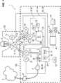
Die Funktionen und das Zusammenwirken von Gasförderungs- und Dosiereinheit zur Förderung von Atemgas, Überwachungsmodul mit Sicherheitsventil, Regelungsmodul zur Druck und Flowregelung im Atemsystem mit Inspirationsventil und Exspirationsventil, Messmodul mit Flow- und Drucksensoren erfolgt in einem Beatmungsgerät auf die nachfolgend beschriebene Weise. Über die Gasförderungs- und Dosiereinheit gelangt das Atemgas über das steuerbare Inspirationsventil in den Patienten und verlässt die Lunge über das Exspirationsventil in die Umgebung. Das Inspirations- und Exspirationsventil steuern sowohl die zugeführte Luftmenge und Atemwegsdruck, als auch die Beatmungsphasen in Form von Inspiration und Exspiration. Ein hierzu notwendiges Regelungsmodul erhält die im Inspirations- und Exspirationszweig befindlichen Flow- und Drucksensoren über das Messmodul, das die Sensorwerte ebenfalls an das Überwachungsmodul sendet. Das Überwachungsmodul, welches von dem Regelungsmodul unabhängig agierend ausgeführt ist, öffnet das Sicherheitsventil, sofern dies durch einen überhöhten Druck im Atemsystem indiziert ist.The functions and the interaction of gas delivery and metering unit for the delivery of breathing gas, monitoring module with safety valve, control module for pressure and flow control in the respiratory system with inspiratory valve and expiratory valve, measuring module with flow and pressure sensors in a ventilator in the manner described below. Via the gas delivery and dosing unit, the respiratory gas enters the patient via the controllable inspiration valve and leaves the lungs via the exhalation valve into the environment. The inspiratory and expiratory valves control both the amount of air supplied and the airway pressure, as well as the ventilation phases in the form of inspiration and expiration. A control module necessary for this purpose receives the flow and pressure sensors located in the inspiratory and expiratory branch via the measuring module, which also sends the sensor values to the monitoring module. The monitoring module, which is designed to be independent of the control module, opens the safety valve if this is indicated by an excessive pressure in the respiratory system.
Das Sicherheitsventil ist hier vorzugsweise als ein federbelastetes Zweistellungs-Solenoid-Ventil ausgeführt, das durch eine Feder im offenen Zustand vorgespannt ist, so dass das Atemgas über das Ventil abfließen kann. Das Sicherheitsventil ist so ausgelegt, dass das Ventil durch Aktivierung des Hubmagnets schließt und der Flow anstelle über das Sicherheitsventil über den Inspirationsschlauch zum Patienten gelangt. Durch die vorgespannte Feder öffnet das Sicherheitsventil bei Stromausfall selbständig, so dass das Beatmungsgerät dann in den sicheren Zustand wechselt.The safety valve is here preferably designed as a spring-loaded two-position solenoid valve, which is biased by a spring in the open state, so that the respiratory gas can flow through the valve. The safety valve is designed so that the valve closes by activation of the solenoid and the flow instead of the safety valve via the inspiratory tube to the patient. Due to the preloaded spring, the safety valve opens automatically in the event of a power failure, so that the ventilator then switches to the safe state.
Üblicherweise sind auch die Inspirations- und Exspirationsventile in vergleichbarer Art realisiert, so dass bei Stromausfall die Zufuhr vom Atemgas über die Schließung des Inspirationsventils automatisch unterbunden wird und durch Öffnen des Exspirationsventils das Atemgas in die Umgebung entweichen kann. Usually, the inspiratory and expiratory valves are realized in a comparable manner, so that in case of power failure, the supply of breathing gas via the closure of the inspiration valve is automatically prevented and can escape by opening the expiratory valve, the breathing gas into the environment.
Die erfindungsgemäße Beatmungsvorrichtung stellt also den Vorteil bereit, eine Auslösewahrscheinlichkeit des Sicherheitsventils im Beatmungsbetrieb derart zu minimieren, wobei wesentlich ist, dass die Aktivierung des Sicherheitsventils dabei nur in denjenigen Situationen erfolgt, in denen eine Druckentlastung über das Exspirationsventil nicht in hinreichend kurzer Zeitdauer erfolgen kann.The ventilation device according to the invention therefore provides the advantage of minimizing a triggering probability of the safety valve in the ventilation mode, wherein it is essential that the activation of the safety valve takes place only in those situations in which a pressure relief via the expiratory valve can not take place in a sufficiently short period of time.
Die erfindungsgemäße Beatmungsvorrichtung, in Ausgestaltung als Anästhesie- oder Beatmungsgerät ist zu einer maschinellen, mandatorischen oder unterstützenden Beatmung eines Patienten ausgestaltet und weist dazu ein Atemsystem mit zu einem Transport von Atemgasen ausgebildeten Verbindungssystem, eine Kontrolleinheit, eine Gasförderungs- und Dosiereinheit, ein Inspirationsventil, ein Exspirationsventil und ein Sicherheitsventil auf.The ventilation device according to the invention, in an embodiment as anesthesia or respirator, is designed for mechanical, mandatory or assisting ventilation of a patient and for this purpose has a breathing system with connection system designed for transporting respiratory gases, a control unit, a gas delivery and dosing unit, an inspiratory valve Exhalation valve and a safety valve on.
Die Beatmungsvorrichtung ist mittels der Kontrolleinheit zu einer Verarbeitung von, von in oder an Messorten der Beatmungsvorrichtung angeordneten Sensoren oder der Beatmungsvorrichtung an zugeordneten Messorten angeordneten Sensoren bereitgestellten Sensorsignalen ausgebildet. Die Sensorsignale indizieren pneumatisch/ fluidisch physikalische Zustände eines Atemgases, insbesondere Druckniveaus oder Druck-Zeitverläufe in einem mit der Beatmungsvorrichtung und einem Patienten gasführend verbundenen und gekoppelten und zu einem Transport von Gasen ausgebildeten gasführenden Verbindungssystem von und zu dem Patienten. Aus den Sensorsignalen können von der Kontrolleinheit Werte von in dem gasführenden Verbindungssystem und im Atemsystem vorhandenen Drücken bestimmt werden. Die Beatmungsvorrichtung ist mittels der Kontrolleinheit zu einer Steuerung und/ oder Regelung von Inspirationsventil, Exspirationsventil und Gasfördereinheit und zu einer Aktivierung und/oder Deaktivierung des Sicherheitsventils ausgestaltet. Steuerung und Regelung von Inspirationsventil, Exspirationsventil und Gasfördereinheit, wie auch Aktivierung und Deaktivierung des Sicherheitsventils erfolgen dabei von der Kontrolleinheit üblicherweise mittels über Steuerleitungen übermittelter Steuersignale.The ventilation device is designed by means of the control unit to process sensor signals provided by sensors arranged in or at measurement locations of the respiration device or sensors arranged at sensors located at associated measurement locations. The sensor signals pneumatically / fluidically indicate physical states of a respiratory gas, in particular pressure levels or pressure-time courses in a gas-conducting connection system from and to the patient, which is gas-conductively connected and coupled to the respiration device and a patient. Values of pressures present in the gas-conducting connection system and in the respiratory system can be determined by the control unit from the sensor signals. The respiratory device is designed by means of the control unit to control and / or regulation of inspiratory valve, expiratory valve and gas delivery unit and to activate and / or deactivate the safety valve. Control and regulation of inspiratory valve, expiratory valve and gas delivery unit, as well as activation and deactivation of the safety valve are carried out by the control unit usually via control signals transmitted via control lines.
Die Kontrolleinheit ist insbesondere in Verbindung mit der Gasförderungs- und Dosiereinheit ist geeignet ausgebildet, das Inspirationsventil, das Exspirationsventil und die Gasfördereinheit und ggf. weitere optionale Dosierelemente und/oder Ventile derart zu steuern oder zu regeln, um einen Ablauf einer Beatmung mit Druckkontrolle oder Volumenkontrolle, Grenzwertüberwachungen für Drücke und Volumina mit Ausgestaltung einer Beatmungsfrequenz und Zeitdauern (I : E) von Inspirationsphase und Exspirationsphasen mittels der Beatmungsvorrichtung am Patienten wirksam werden zu lassen.The control unit is designed, in particular in conjunction with the gas delivery and metering unit, to control or regulate the inspiration valve, the expiratory valve and the gas delivery unit and, if appropriate, further optional metering elements and / or valves in order to perform a course of ventilation with pressure control or volume control , Limit controls for pressures and volumes with design of a ventilation frequency and durations (I: E) of inspiratory phase and expiratory phases using the ventilator on the patient to take effect.
Die Kontrolleinheit ist dabei vorzugsweise als ein Mikroprozessor-Modul (µC) mit zugeordnetem internen und/ oder externen Datenspeicher (RAM) ausgestaltet. Die Kontrolleinheit ist zur Ausführung der Funktionen mit Analysen, Vergleichs-Operationen, Berechnungen und Bewertungen beispielsweise durch Hardware-Bausteine als µC, µP, DSP, FPGA, ASIC ausgebildet, die beispielsweise in Form eines Prozessors (µP), mehrerer Prozessoren oder in Form von Instruktionen in einem Speicherbereich implementiert sein können, die durch den Prozessor verarbeitet werden.The control unit is preferably designed as a microprocessor module (μC) with associated internal and / or external data memory (RAM). The control unit is designed to perform the functions with analyzes, comparison operations, calculations and evaluations, for example by hardware components as .mu.C, .mu.P, DSP, FPGA, ASIC, for example in the form of a processor (μP), multiple processors or in the form of Instructions may be implemented in a memory area processed by the processor.
Die Kontrolleinheit in der Beatmungsvorrichtung kann derart ausgestaltet sein, dass die Ablaufsteuerung der Beatmung und die Aktivierung, wie auch die Deaktivierung des Sicherheitsventils unabhängig voneinander bewirkbar sind. So kann die Kontrolleinheit in zwei voneinander unabhängigen µP-, CPU- oder Recheninstanzen, beispielsweise als Beatmungsmodul für Kontrolle und Ablauf der Beatmung und als ein Überwachungsmodul zur Überwachung von Drucksituationen im Atemsystem ausgestaltet sein. Dabei werden die Messwerte, welche pneumatisch/ fluidisch physikalische Zustände des Atemgases indizieren von dem Messmodul sowohl dem Überwachungsmodul, als auch dem Regelungsmodul bereitgestellt.The control unit in the respiratory device can be designed such that the sequence control of the ventilation and the activation as well as the deactivation of the safety valve can be effected independently of one another. Thus, the control unit in two independent μP, CPU or computing instances, for example, as a ventilation module for control and flow of ventilation and be designed as a monitoring module for monitoring pressure situations in the respiratory system. In this case, the measured values which indicate pneumatic / fluidic physical states of the respiratory gas are provided by the measuring module both to the monitoring module and to the control module.
In der Beatmungsvorrichtung mit
- - einem Atemsystem mit einem zu einem Transport von Atemgasen ausgebildeten Verbindungssystem,
- - einer Sensorik mit mindestens einem Drucksensor
- - einer Gasförderungs- und Dosiereinheit mit einem Inspirationsventil und einem Exspirationsventil,
- - einem Sicherheitsventil,
- - einer Kontrolleinheit zu einer Kontrolle eines kontinuierlichen Beatmungsbetriebes in Zusammenwirkung mit der Gasförderungs- und Dosiereinheit und auf Basis von, bereitgestellter Messwerte der Sensorik, dem Inspirationsventil und dem Exspirationsventil,
- - Vergleich eines, einen Druck in dem Atemsystem indizierenden Messwertes mit einem ersten Vergleichskriterium bezüglich eines Vorliegens einer Druckerhöhung im Atemsystem,
- - Vergleich mindestens eines weiteren, einen Druck in dem Atemsystem indizierenden Messwertes mit einem zweiten Vergleichskriterium zu einer Bestimmung bezüglich eines Vorliegens einer ersten oder einer zweiten Drucksituation im Atemsystem auf Basis des Vergleichs,
- o wobei die erste Drucksituation im Atemsystem dadurch charakterisierbar ist, dass mittels der Analyse eine Situation mit einem im weiteren zeitlichen Verlauf abnehmenden Druck im Atemsystem mit einer Unterschreitung eines vorbestimmten Druckniveaus innerhalb einer vorbestimmten Zeitdauer abschätzbar ist,
- o wobei die zweite Drucksituation im Atemsystem dadurch charakterisierbar ist, dass mittels der Analyse eine Situation mit einem im weiteren zeitlichen Verlauf abnehmenden Druck im Atemsystem mit der Unterschreitung des vorbestimmten Druckniveaus innerhalb der vorbestimmten Zeitdauer nicht abschätzbar ist,
- o wobei in dem Falle, dass die zweite Drucksituation gegeben ist, eine Aktivierung eines Sicherheitsventils durch die Kontrolleinheit erfolgt.
- a breathing system with a connection system designed for the transport of respiratory gases,
- - A sensor with at least one pressure sensor
- a gas delivery and metering unit with an inspiratory valve and an expiratory valve,
- - a safety valve,
- a control unit for controlling a continuous ventilation operation in cooperation with the gas delivery and dosing unit and on the basis of provided measurement values of the sensor system, the inspiration valve and the expiration valve,
- Comparing a measured value indicative of a pressure in the respiratory system with a first comparative criterion with regard to the presence of an increase in pressure in the respiratory system,
- Comparison of at least one further measured value indicative of a pressure in the respiratory system with a second comparison criterion for a determination with regard to the presence of a first or a second pressure situation in the respiratory system on the basis of the comparison,
- o wherein the first pressure situation in the respiratory system can be characterized by the fact that by means of the analysis a situation with a decreasing pressure in the respiratory system in the further course of time can be estimated within a predetermined period of time, with a drop below a predetermined pressure level,
- wherein the second pressure situation in the respiratory system can be characterized by the fact that a situation with a decreasing pressure in the breathing system during the further course of time can not be estimated by the analysis within the predetermined time period,
- o wherein in the event that the second pressure situation is given, an activation of a safety valve by the control unit takes place.
Das Atemsystem mit Verbindungsystem weist einen exspiratorischen Pfad auf, welcher zu einer Fortführung einer exspiratorischen Menge an Atemgas von dem Patienten ausgebildet und vorgesehen ist.The breathing system with the connection system has an expiratory path which is designed and provided for the continuation of an expiratory amount of breathing gas from the patient.
Das Atemsystem mit Verbindungsystem weist einen inspiratorischen Pfad auf, welcher zu einer Hinführung einer inspiratorischen Menge an Atemgas von der Beatmungsvorrichtung zu dem Patienten ausgebildet und vorgesehen ist. Das Atemsystem mit Verbindungsystem weist einen Patientenverbindungs-Pfad, beispielsweise ausgeführt als eine Patientengaszuführungsleitung in Form eines Endotracheal-Tubus auf, welcher zu einer Hinführung der inspiratorischen Menge an Atemgas von der Beatmungsvorrichtung zu dem Patienten und zu einer Fortführung der exspiratorischen Menge an Atemgas von dem Patienten ausgebildet und vorgesehen ist. Der exspiratorische Pfad und der inspiratorische Pfad sind vorzugsweise mittels eines Verbindungselements miteinander und mit dem Patientenverbindungs-Pfad verbunden. Das Verbindungselement ist in der Praxis oftmals als ein sogenanntes Y-Stück ausgebildet.The breathing system with connection system has an inspiratory path, which is designed and provided for an introduction of an inspiratory amount of breathing gas from the ventilator to the patient. The breathing system with connection system includes a patient connection pathway, embodied, for example, as a patient gas supply line in the form of an endotracheal tube, leading to inspiratory amount of breathing gas from the ventilator to the patient and continuing the expiratory amount of breathing gas from the patient is designed and provided. The expiratory path and the inspiratory path are preferably connected to each other and to the patient connection path by means of a connector. The connecting element is often formed in practice as a so-called Y-piece.
Zur Erfassung der Messwerte der Sensorik ist vorzugsweise ein Messmodul in der Beatmungsvorrichtung vorgesehen. Das Messmodul kann in oder an der Kontrolleinheit angeordnet oder der Kontrolleinheit zugeordnet oder als ein Bestandteil der Kontrolleinheit ausgebildet sein. In einer optionalen Weiterbildung kann in dem Atemsystem als weitere Sensorik mindestens ein Durchflussmengensensor angeordnet sein. Das Messmodul ist zu einer Erfassung von Messwerten der Sensorik ausgebildet. Das Messmodul ist zu einer Umwandlung von physikalischen Messgrößen indizierenden elektrischen Signalen, welche von der Sensorik mit dem mindestens einen Drucksensor bereitgestellt werden, in zu einer weiteren Datenverarbeitung geeignete Datensignale, sowie deren Bereitstellung ausgestaltet.For detecting the measured values of the sensor system, a measuring module is preferably provided in the respiratory device. The measuring module can be arranged in or on the control unit or assigned to the control unit or designed as a component of the control unit. In an optional further development, at least one flow rate sensor can be arranged in the breathing system as a further sensor system. The measuring module is designed to detect measured values of the sensor system. The measuring module is configured to convert physical measured variables indicating electrical signals, which are provided by the sensor system with the at least one pressure sensor, into data signals suitable for further data processing, and to make them available.
Der mindestens eine Drucksensor als Element der Sensorik ist in oder an der Beatmungsvorrichtung, in oder an dem Atemsystem oder in oder an dem Verbindungssystem angeordnet und dazu vorgesehen ist, einen Messwert eines Druckes zu erfassen, welcher einen Druck im Atemsystem indiziert und/ oder somit in dem Atemsystem vorhanden ist oder herrscht. Das Messmodul ist ausgebildet, diesen mindestens einen Messwert der Kontrolleinheit, wie auch insbesondere dem Regelungsmodul und dem Überwachungsmodul bereitzustellen. Die Messwerte des mindestens einen Drucksensors indizieren einen Druck, sowie dessen zeitlichen Verlauf im Atemsystem der Beatmungsvorrichtung.The at least one pressure sensor as an element of the sensor system is arranged in or on the respiratory device, in or on the respiratory system or in or on the connection system and is intended to detect a measured value of a pressure which indicates a pressure in the respiratory system and / or thus in the respiratory system is present or prevails. The measuring module is designed to provide this at least one measured value of the control unit, as well as in particular the control module and the monitoring module. The measured values of the at least one pressure sensor indicate a pressure, as well as its time course in the respiratory system of the respiratory device.
Zur Durchführung des kontinuierlichen Beatmungsbetriebes der Beatmungsvorrichtung ist vorzugsweise ein Regelungsmodul (control unit) in der Beatmungsvorrichtung vorgesehen. Dies Regelungsmodul kann in oder an der Kontrolleinheit angeordnet oder der Kontrolleinheit zugeordnet oder als ein Bestandteil der Kontrolleinheit ausgebildet sein und ist bei der Durchführung des Beatmungsbetriebes zu einer Bewirkung von Einstellungen von Beatmungsdrücken und Durchflussmengen an Atemgas ausgebildet. Die Einstellungen können dabei als Stellwerte sowohl in Form von Steuerungen (open loop control) wie auch von Regelungen (closed loop control) in den von Kontrolleinheit und Gasförderungs- und Dosiereinheit ausgestalteten Beatmungsbetrieb mit Inspirationsphasen und Exspirationsphasen wirksam werden. Die Gasförderungs- und Dosiereinheit mit dem Inspirationsventil und dem Exspirationsventil in Zusammenwirkung mit der Kontrolleinheit, bzw. dem Messmodul und dem Regelungsmodul ermöglichen eine Zuführung von Atemgasen hin zum Patienten und eine Fortführung von Atemgasen vom Patienten fort. Wird dem Patienten inspiratorisch eine Menge an Atemgas zugeführt, so erfolgt die Dosierung der Menge an Atemgas über den inspiratorischen Zweig des Verbindungssystems mit Hilfe der Einstellung des Inspirationsventils, wobei das Exspirationsventil geschlossen wird, so dass die Menge an Atemgas in die Lunge des Patienten einströmen kann. Exspiratorisch erfolgt die Ausatmung des Patienten über das ganz oder teilweise geöffnete Exspirationsventil über den exspiratorischen Zweig des Verbindungssystems, wobei das Inspirationsventil derart eingestellt ist, dass vom Patient über den inspiratorischen Zweig des Verbindungssystems keine Mengen an Atemgas in die Beatmungsvorrichtung strömen können. Ein nur teilweise geöffnetes Exspirationsventil dient dabei mittels einer definiert von der Kontrolleinheit, bzw. dem Regelungsmodul eingestellte, gesteuerten oder geregelten Druckentlastung einer Erzeugung und Bereitstellung des positiven endexspiratorischen Drucks (Positive End-Expiratory Pressure, PEEP) für den Patienten. Die Strömungsrichtungen der strömenden Mengen an Atemgas sind mittels zweier passiver Rückschlagventile definiert, sodass exspiratorisch keine Strömungen an Atemgas von der Beatmungsvorrichtung zum Patienten hin und inspiratorisch keine Strömungen vom Patienten in die Beatmungsvorrichtung hinein ermöglicht sind. Das Sicherheitsventil ist im inspiratorischen Zweig des Verbindungssystems - in Relation zur Strömungsrichtung von der Beatmungsvorrichtung zum Patienten hin - stromabwärts des passiven inspiratorischen Rückschlagventils angeordnet. Diese Anordnung stellt sicher, dass eine Öffnung des Sicherheitsventils bei einer Druckerhöhung im Atemsystem oder Verbindungssystem, welche vom Überwachungsmodul überwacht wird, eine Druckentlastung für den Patienten ermöglicht wird.To carry out the continuous ventilation operation of the respiratory device, a control module (control unit) is preferably provided in the respiratory device. This control module may be arranged in or on the control unit or assigned to the control unit or formed as part of the control unit and is in the implementation of the ventilation operation to effect settings of ventilation pressures and flow rates of breathing gas. The settings can Here are as control values both in the form of controls (open loop control) as well as regulations (closed loop control) in the designed by control unit and gas pumping and dosing ventilator with inspiratory phases and expiratory effective. The gas delivery and metering unit with the inspiratory valve and the expiratory valve, in cooperation with the control unit or the measuring module and the control module, allow the supply of respiratory gases to the patient and the continuation of respiratory gases from the patient. When an inspiratory amount of breathing gas is supplied to the patient, the amount of breathing gas is metered via the inspiratory branch of the connection system by the inspiratory valve setting, closing the expiratory valve so that the amount of breathing gas can flow into the patient's lungs , Exhaling the exhalation of the patient via the fully or partially open expiratory valve via the expiratory branch of the connection system, wherein the inspiration valve is set such that the patient can not flow on the inspiratory branch of the connection system, no amounts of breathing gas into the ventilator. A partially opened expiratory valve serves by means of a controlled or regulated pressure relief defined by the control unit or the control module to generate and provide the positive end-expiratory pressure (PEEP) to the patient. The flow directions of the flowing amounts of respiratory gas are defined by means of two passive check valves, so that expiratory flow of respiratory gas from the respirator to the patient and inspiratory no flows from the patient into the ventilator are possible. The safety valve is located in the inspiratory branch of the connection system, downstream of the passive inspiratory check valve, in relation to the direction of flow from the ventilator to the patient. This arrangement ensures that an opening of the safety valve at a pressure increase in the breathing system or connection system, which is monitored by the monitoring module, a pressure relief for the patient is made possible.
Auf diese Weise können dann in Zusammenwirkung von Kontrolleinheit, bzw. Überwachungsmodul für den Patienten durch überhöhte Atemwegsdrücke möglicherweise entstehende gesundheitsgefährdende Situationen vermieden werden.In this way, health-threatening situations which may possibly arise due to excessive airway pressures can then be avoided in cooperation with the control unit or monitoring module for the patient.
Die Kontrolleinheit ist, vorzugsweise mittels einer Schnittstelle, geeignet ausgebildet, Messwerte, vorzugsweise von dem Messmodul zu empfangen oder über eine oder mehrere Datenverbindungen einzulesen.The control unit is designed, preferably by means of an interface, to receive measured values, preferably from the measuring module, or to read them in via one or more data connections.
In üblichen Konfigurationen von Anästhesie- und Beatmungsgeräten sind das Messmodul und das Regelungsmodul als Elemente oder Module der Kontrolleinheit ausgeführt. Die Kontrolleinheit ist auf diese Weise mit dem Regelungsmodul und dem Messmodul in Verbindung mit der Gasförderungs- und Dosiereinheit geeignet ausgebildet, eine Anordnung von Ventilen, im Wesentlichen das Inspirationsventil und das Exspirationsventil geeignet zu steuern oder zu regeln, um den Beatmungsbetrieb Ablauf einer Beatmung mit Druckkontrolle oder Volumenkontrolle, Grenzwertüberwachungen für Drücke und Volumina mit Ausgestaltung einer Beatmungsfrequenz und Zeitdauern (I : E) von Inspirationsphase und Exspirationsphasen mittels der Beatmungsvorrichtung am Patienten wirksam werden zu lassen.In common anesthesia and ventilator configurations, the measurement module and the control module are implemented as elements or modules of the control unit. The control unit is designed in this way with the control module and the measuring module in conjunction with the gas delivery and metering unit adapted to control or regulate an array of valves, essentially the inspiratory valve and the expiratory valve to control the ventilation operation of respiratory control with pressure control or volume control, limit monitoring for pressures and volumes with the design of a ventilation frequency and time periods (I: E) of inspiratory phase and expiratory phases by means of the ventilator on the patient to take effect.
Zur Überwachung von in dem Atemsystem gegeben Drücken wie auch von Druckverläufen in dem Atemsystem ist ein Überwachungsmodul in der Beatmungsvorrichtung vorgesehen. Dies Überwachungsmodul kann in oder an der Kontrolleinheit angeordnet oder der Kontrolleinheit zugeordnet oder als ein Bestandteil der Kontrolleinheit ausgebildet sein. Das Überwachungsmodul ist zu einer Bewertung von Messwerten und/ oder Messwertverläufen der Sensorik, Vergleichen von Messwerten, welche Drücke oder Druckverläufe im Atemsystem indizieren mit Druckschwellenwerten und zu einer Analyse von Betriebszuständen der Beatmungsvorrichtung ausgebildet.In order to monitor pressures in the respiratory system as well as pressure profiles in the respiratory system, a monitoring module is provided in the ventilator. This monitoring module can be arranged in or on the control unit or assigned to the control unit or designed as a component of the control unit. The monitoring module is designed to evaluate measured values and / or measured values of the sensor system, compare measured values which indicate pressures or pressure profiles in the respiratory system with pressure threshold values and to analyze operating states of the respiratory device.
Die Kontrolleinheit ist damit mittels Messmodul und Überwachungsmodul dazu geeignet ausgebildet, den erfassten ersten Messwert, welcher einen Druck im Atemsystem indiziert, mit einem vorbestimmten ersten Druckschwellenwert zu vergleichen und auf Basis des Vergleichs festzustellen, ob der erfasste Messwert einen überhöhten Druck im Atemsystem der Beatmungsvorrichtung indiziert. Die Druckschwellenwerte werden dabei der Kontrolleinheit vom Datenspeicher bereitgestellt.By means of the measuring module and monitoring module, the control unit is thus designed to compare the detected first measured value, which indicates a pressure in the respiratory system, with a predetermined first pressure threshold value and to determine on the basis of the comparison whether the detected measured value indicates an excessive pressure in the respiratory system of the respiratory device , The pressure thresholds are thereby provided to the control unit from the data memory.
Die Ausgestaltung der Kontrolleinheit in Regelungsmodul und Überwachungsmodul ermöglicht in vorteilhafter Weise, dass die Ablaufsteuerung der Beatmung und Aktivierung, wie auch Deaktivierung des Sicherheitsventils unabhängig voneinander bewirkbar sind. Damit kann in Situationen, in denen eine Druckerhöhung im Atemsystem gegeben ist, das Überwachungsmodul unabhängig vom Zustand des Exspirationsventils und/ oder dem Exspirationsventil zugeordneten Regelsystemen im Regelungsmodul und deren Zuständen, eine Öffnung des Sicherheitsventils bewirken und damit eine Druckentlastung im Atemsystem bewirken. Dabei kann in vorteilhafter Weise diese unabhängige Einwirkung von Regelungsmodul und Überwachungsmodul auf den Betrieb des Beatmungsgerätes auf Basis der vom Messmodul gelieferten Messdaten, insbesondere von Messdaten, welche einen Druck im Atemsystem indizieren, erfolgen. Das bedeutet für die praktische Ausgestaltung, dass das Messmodul ausgestaltet sein kann, sowohl für das Überwachungsmodul, als auch das Regelungsmodul die für die jeweilige Funktion benötigten Messdaten, insbesondere der Messdaten, welche den Druck im Atemsystem indizieren, bereitzustellen.The design of the control unit in control module and monitoring module advantageously allows the flow control of the ventilation and activation, as well as deactivation of the safety valve can be effected independently of each other. Thus, in situations where there is an increase in pressure in the respiratory system, the monitoring module regardless of the state of the expiratory valve and / or the exhalation valve associated control systems in the control module and their states, causing an opening of the safety valve and thus cause a pressure relief in the breathing system. It can this independent action of regulation module and monitoring module advantageously takes place on the operation of the ventilator on the basis of the measurement data supplied by the measurement module, in particular of measurement data which indicate a pressure in the respiratory system. For the practical embodiment, this means that the measuring module can be configured to provide both the monitoring module and the control module with the measurement data required for the respective function, in particular the measurement data which indicates the pressure in the respiratory system.
Der Vergleich des, den Druck in dem Atemsystem indizierenden ersten Messwertes mit dem ersten Vergleichskriterium kann vorzugsweise mit Hilfe eines ersten Vergleichsdruckwertes erfolgen. Der Vergleichsdruckwert indiziert dabei eine Situation einer unzulässigen Druckerhöhung in dem Atemsystem. Ein möglicher Vergleichsdruckwert ist beispielsweise ein vorbestimmter Druckschwellenwert.The comparison of the first measured value indicating the pressure in the respiratory system with the first comparative criterion can preferably be carried out with the aid of a first comparative pressure value. The comparison pressure value indicates a situation of an impermissible pressure increase in the respiratory system. A possible comparison pressure value is, for example, a predetermined pressure threshold value.
Als eine Variante des ersten Vergleichskriteriums kann dabei ein mathematischer Vergleichsoperator > oder ≥ gewählt werden, um den aktuellen Messwert in Bezug zum Vergleichsdruckwert zu setzen und eine Überschreitung des vorbestimmten Druckschwellenwertes gewählt werden. So charakterisiert beispielsweise ein Druckwert oberhalb eines Druckschwellenwertes, beispielsweise von 30 hPa ± 3 hPa, einen erhöhten Druck im Atemsystem für einen erwachsenen Patienten und kann damit das erste Vergleichskriterium repräsentieren, welches die Situation einer unzulässigen Druckerhöhung in dem Atemsystem indiziert.As a variant of the first comparison criterion, a mathematical comparison operator oder or ≥ can be selected in order to set the current measured value in relation to the comparison pressure value and an exceeding of the predetermined pressure threshold value can be selected. For example, a pressure above a threshold pressure value, for example of 30 hPa ± 3 hPa, characterizes an increased pressure in the respiratory system for an adult patient and may thus represent the first comparison criterion indicating the situation of an impermissible pressure increase in the respiratory system.
Zusätzlich kann das erste Vergleichskriterium ein Zeitkriterium aufweisen.In addition, the first comparison criterion may have a time criterion.
Als eine solche alternative Variante des ersten Vergleichskriteriums in Kombination mit einem Zeitkriterium kann beispielsweise eine Überschreitung des vorbestimmten Druckschwellenwertes für eine vorbestimmte zeitliche Mindestzeitdauer gewählt werden. So charakterisiert beispielsweise eine Zeitdauer von 0,02 Sekunden bis 0,05 Sekunden eine zeitliche Mindestdauer und charakterisiert in Verbindung mit einem Druckwert oberhalb eines Druckschwellenwertes, beispielsweise von 30 hPa ± 3 hPa, einen erhöhten Druck im Atemsystem für einen erwachsenen Patienten und kann als eine Druckschwellenwert/ Zeitdauer-Kombination das erste Vergleichskriterium repräsentieren, welches die Situation einer unzulässigen Druckerhöhung in dem Atemsystem indiziert. Die von der Kontrolleinheit, vorzugsweise und insbesondere von dem Überwachungsmodul, durchgeführte Analyse des mindestens einen, den Druck in dem Atemsystem indizierenden ersten Messwertes und des mindestens einen weiteren, den Druck in dem Atemsystem indizierenden Messwertes mit dem mindestens einem Vorgabewert mit der Unterscheidung bezüglich des Vorliegens der ersten oder der zweiten Drucksituation im Atemsystem hat den Zweck, zu ermitteln, welche Situation des Drucks im Atemsystem gegeben ist und ob, basierend auf dem Vorliegen der ersten oder zweiten Drucksituation von der Kontrolleinheit die Aktivierung des Sicherheitsventil zur Druckentlastung im Atemsystem zu bewirken ist. Im Falle, dass die zweite Drucksituation gegeben ist, erfolgt eine Aktivierung des Sicherheitsventils durch die Kontrolleinheit.As such an alternative variant of the first comparison criterion in combination with a time criterion, for example, an exceeding of the predetermined pressure threshold value for a predetermined minimum time period of time can be selected. For example, a time period of 0.02 seconds to 0.05 seconds characterizes a minimum time duration and, in conjunction with a pressure above a threshold pressure value, for example of 30 hPa ± 3 hPa, characterizes an elevated pressure in the respiratory system for an adult patient Pressure threshold / duration combination represent the first comparison criterion, which indicates the situation of an impermissible pressure increase in the respiratory system. The analysis performed by the control unit, preferably and in particular by the monitoring module, of the at least one first measured value indicative of the pressure in the respiratory system and of the at least one further measured value indicative of the pressure in the respiratory system with the at least one default value with the distinction with respect to the presence The first or the second pressure situation in the respiratory system has the purpose of determining which situation of the pressure in the respiratory system is present and whether, based on the presence of the first or second pressure situation of the control unit, the activation of the safety valve to relieve pressure in the respiratory system. In the event that the second pressure situation is given, the safety valve is activated by the control unit.
Die Unterscheidung in die erste Drucksituation oder die zweite Drucksituation kann, wie in verschiedenen Ausführungsformen nachfolgend näher erläutert darlegt erfolgen. In den verschiedenen Ausführungsformen erfolgt die Analyse des ersten Druckwertes und des mindestens einen weiteren Druckwertes zur Ermittlung der Drucksituation auf eine oder mehrere der nachfolgend beschriebenen Weisen.The distinction in the first pressure situation or the second pressure situation can, as explained in more detail below in various embodiments set forth. In the various embodiments, the analysis of the first pressure value and of the at least one further pressure value for determining the pressure situation takes place in one or more of the ways described below.
Gemeinsam ist in diesen Ausführungsformen, dass von der Kontrolleinheit ein dekrementieller Verlauf des Drucks im Atemsystem im weiteren zeitlichen Verlauf des kontinuierlichen Beatmungsbetriebs mit der Unterschreitung des vorbestimmten Druckniveaus innerhalb einer vorbestimmten Zeitdauer abgeschätzt wird.It is common in these embodiments that the control unit estimates a decremental course of the pressure in the respiratory system during the further course of the continuous ventilation operation with the pressure level falling below the predetermined pressure level within a predetermined period of time.
So können die erste und/oder die zweite Drucksituation nach einer bevorzugten Ausführungsform mittels einer Abschätzung aus dem weiteren, an die erste und/ oder zweite Drucksituation zeitlich nachfolgenden Druckverlauf abschätzbar sein.Thus, according to a preferred embodiment, the first and / or the second pressure situation can be estimated by means of an estimation from the further pressure progression chronologically following the first and / or second pressure situation.
Die Abschätzung des weiteren Druckverlaufs kann beispielsweise mittels einer Trendabschätzung, mittels einer vergleichenden Analyse mit einem Vergleichsdruckverlauf, mittels eines Vergleichs einer prognostizierbaren Abfolge von Unter- bzw. Überschreitungen einer der Abfolge zugehörigen Anzahl von Druckschwellenwerten oder mittels mathematischer Methoden, wie linearer oder nichtlinearer Interpolation, exponentieller Interpolation, Polynom- oder Spline-Interpolation ausgeführt werden. Eine solche Abschätzung kann derart ausgestaltet sein, dass, wenn der Vergleich des ersten, den Druck in dem Atemsystem indizierenden Messwertes mit dem ersten Vergleichskriterium ergibt, dass zu einem ersten Zeitpunkt im Atemsystem ein überhöhter Atemwegsdruck gegeben ist, mindestens ein weiterer Messwert mit dem ersten Messwert verglichen wird. Dabei wird der erste Messwert von der Kontrolleinheit, vorzugsweise mittels des Messmoduls erfasst und steht damit der Kontrolleinheit zur Analyse und Abschätzung bereit. Der mindestens eine weitere Messwert wird dabei zu einem zu einem weiteren, nach einer Beobachtungszeitdauer gewählten Zeitpunkt, zeitlich nachfolgend nach dem Zeitpunkt der Erfassung des ersten Messwerts von der Kontrolleinheit, vorzugsweise mittels des Messmoduls erfasst und steht damit der Kontrolleinheit ebenfalls zur Analyse und Abschätzung bereit. Zur Ausgestaltung der Ausführungsformen der Analyse, insbesondere der Abschätzung und zur Ausgestaltung der Aktivierung des Sicherheitsventils stehen der Kontrolleinheit folgende Größen oder Kriterien gemäß der in Tabelle 2 nachfolgenden Auflistung jeweils für sich, wie auch zu Kombinationen miteinander bereit: Tabelle 2
Nachfolgend wird beschrieben, was im Sinne der vorliegenden Erfindung unter den in Tabelle 2 gelisteten Ausgestaltungen a) bis I) von Analyse und Abschätzung zu verstehen ist.
- a) Unter der Variabilität der Beobachtungszeitdauer ist die Zeitdifferenz zwischen dem Zeitpunkt der Erfassung des ersten Messwertes, welcher den Druck in dem Atemsystem indiziert und dem mindestens einen weiteren oder einer Vielzahl weiterer Messwerte, welche Drücke in dem Atemsystem indizieren, zu verstehen.
- b) Unter Druckdifferenzen von Messwerten im zeitlichen Verlauf sind Druckdifferenzen ΔP von Messwerten zwischen dem ersten Messwert und dem mindestens einen weiteren Messwert oder der Vielzahl weiterer Messwerte zu verstehen.
- c) Unter zeitlichen Ableitungen von Druckänderungen oder Druckdifferenzen sind zeitliche Ableitungen von Druckänderungen oder Druckdifferenzen

- d) Unter physikalischen Latenzzeiten sind Latenzzeiten von Druckänderungen im Zeitverlauf, bedingt durch strömungstechnische Eigenschaften im Atemsystem, wie Strömungswiderstände, Volumina, Elastizität von Schlauchsystemen zu verstehen. Dabei zählen durch zum Druckausgleich bedingte Ausgleichsströmungen im Atemsystem hervorgerufene Zeitverzögerungen oder auch durch die Schallgeschwindigkeit bedingte Druckausbreitungsverzögerungen.
- e) Unter systemischen Latenzzeiten sind durch Signalerfassung, Signalfilterung, Datenwandlung, Datenverarbeitung, Datenverteilung und durch Berechnungen im Betrieb von Beatmungsvorrichtung, Regelungsmodul, Überwachungsmodul Messmodul bedingte Latenzzeiten zu verstehen. Des Weiteren sind unter den systemischen Latenzzeiten auch bei Ansteuerung zur Einstellung bzw. Aktivierung oder Deaktivierung von Aktuatoren wie beispielsweise Inspirationsventil, Exspirationsventil, Sicherheitsventil vorhandene Totzeiten, Verzögerungszeiten und elektrischmechanische Umsetzungszeiten (Reaktionszeiten) zu verstehen. Die Einbeziehung von bekannten systemischen Latenzzeiten der Beatmungsvorrichtung, des Regelungsmoduls, des Überwachungsmoduls oder des Messmoduls können sich beispielsweise bei der Aktivierung des Sicherheitsventils von dem Aktivierungsbefehl im Überwachungsmodul, über die elektrische Aktivierung mittels Steuersignal am Ventil bis zum physikalischen Öffnungszustand des Ventils ergeben.
- f) Unter einem Druck-Zeitprodukt (PTP, Pressure Time Product) ist das Produkt aus Druckmesswerten mit Zeitintervallen zu verstehen. Das Druck-Zeitprodukt indiziert oder charakterisiert dabei Zustände von Gasmengen im Atemsystem. Das Druck-Zeitprodukt (PTP, Pressure Time Product) wird gebildet aus Drücken, Druckdifferenzen oder Druckverläufen multipliziert mit einer Zeitdauer. Das Druck-Zeitprodukt ist vorteilhaft, um nach der Erkenntnis, dass im Atemsystem ein überhöhter Atemwegsdruck gegeben ist, die Folgen hinsichtlich des zu erwartenden weiteren Druckverlaufs, insbesondere eines weiteren Druckanstieges zu berücksichtigen. Das Druck-Zeitprodukt ist damit eine Möglichkeit, die das Gewicht oder Bedeutung einer Druckänderung im Atemsystem oder Gewicht, bzw. Bedeutung einer Änderung des Atemwegsdrucks hervorzuheben oder zu veranschaulichen und bietet die Möglichkeit, verschiedene Situationen vergleichbar zu machen. So kann auf diese Weise ein starker Druckanstieg in einem sehr kurzen Zeitintervall mit einem moderaten Druckanstieg über eine längere Zeitdauer mittels des Druck-Zeitprodukts verglichen werden. Auch hinsichtlich der Abschätzung einer Wirkung einer Druckentlastung bietet das Druck-Zeitprodukt den Vorteil, dass es abschätzbar wird, welche Druckentlastung sich beispielsweise für eine verbleibende Dauer einer aktuellen Exspirationsphase durch eine Öffnung des Sicherheitsventils ergeben kann oder erzielt werden muss.
- g) Unter aktuellen Situationen im Beatmungsverlauf sind beispielsweise Beginn, Mitte oder Ende von Exspirationsphase oder von Inspirationsphase, wie auch inspiratorische Pausen oder exspiratorische Pausen im Verlauf der Beatmung zu verstehen.
- h) Unter Durchflussmengen von Gasmengen sind Durchflussmengen an Ein- und/oder Ausatemgasen hin zum Patienten und/oder fort vom Patienten, wie auch Bilanzierungen von Durchflussmengen an Ein- und/oder Ausatemgasen hin zum Patienten und/oder fort vom Patienten zu verstehen.
- i) Unter Strömungsgeschwindigkeiten von Gasmengen sind Strömungsgeschwindigkeiten im Verbindungssystem zu verstehen.
- j) Unter Strömungsrichtungen von Gasmengen sind Strömungsrichtungen im Verbindungssystem, wie auch Strömungsrichtungen an Ein- und/oder Ausatemgasen hin zum Patienten und/oder fort vom Patienten, wie auch Bilanzierungen von Strömungsrichtungen an Ein- und/oder Ausatemgasen hin zum Patienten und/oder fort vom Patienten zu verstehen.
- k) Unter Volumen- oder Volumina-Verschiebungen sind Verschiebungen oder Bewegungen von Volumen oder Volumina an Ein- und/oder Ausatemgasen hin zum Patienten und/oder fort vom Patienten, wie auch Bilanzierungen von Verschiebungen oder Bewegungen von Volumen oder Volumina an Ein- und/oder Ausatemgasen hin zum Patienten und/oder fort vom Patienten zu verstehen.
- l) Unter Alarm- und Warnsituationen im Betrieb des Beatmungsgerätes sind Alarme, welche einen Mangel oder ein Übermaß von Druck, Durchflussmenge oder Volumen kennzeichnen zu verstehen, wie beispielsweise Pawhigh, VTLow, MVLow.

- a) Among the variability of the observation period, the time difference between the time of detection of the first measurement, which indicates the pressure in the respiratory system and the at least one other or a plurality of further measurements, which indicate pressures in the respiratory system, to understand.
- b) Pressure differences between measured values over time are pressure differences ΔP of measured values between the first measured value and the at least one further measured value or the multiplicity of further measured values.
- c) Temporal derivatives of pressure changes or pressure differences are time derivatives of pressure changes or pressure differences
- d) Physical latencies are latencies of pressure changes over time due to fluidic properties in the respiratory system, such as flow resistance, volumes, elasticity of hose systems to understand. Counting caused by pressure equalization compensatory flows in the respiratory system caused time delays or due to the speed of sound pressure propagation delays include.
- e) Systemic latencies are understood to mean latencies due to signal acquisition, signal filtering, data conversion, data processing, data distribution, and operational calculations of the respiratory device, control module, monitoring module, measurement module. Furthermore, under the systemic latencies, even when activated for setting or activating or deactivating actuators, such as inspiratory valve, expiration valve, safety valve, existing dead times, delay times and electrical mechanical conversion times (reaction times) are to be understood. The inclusion of known systemic latencies of the respiratory device, the control module, the monitoring module or the measuring module may result, for example, in the activation of the safety valve from the activation command in the monitoring module, via the electrical activation by means of control signal on the valve to the physical opening state of the valve.
- f) Pressure Time Product (PTP) is the product of pressure readings with time intervals. The pressure-time product indicates or characterizes states of gas quantities in the respiratory system. The Pressure Time Product (PTP) is made up of pressures, pressure differences or pressure curves multiplied by a period of time. The pressure-time product is advantageous in order to take into account the consequences with regard to the expected further pressure curve, in particular a further pressure increase, after the knowledge that an excessive airway pressure is given in the respiratory system. The pressure-time product is thus a way to highlight or illustrate the weight or importance of a pressure change in the respiratory system or weight, or importance of a change in airway pressure and provides the ability to make different situations comparable. Thus, in this way, a large pressure increase in a very short time interval can be compared with a moderate pressure increase over a longer period of time by means of the pressure-time product. Also with regard to the estimation of an effect of a pressure relief, the pressure-time product offers the advantage that it can be estimated which pressure relief can be achieved, for example, for a remaining duration of a current expiratory phase by opening the safety valve or must be achieved.
- g) Current situations in the course of ventilation include, for example, the beginning, middle or end of the expiratory phase or of the inspiratory phase, as well as inspiratory pauses or expiratory pauses during the course of ventilation.
- h) Flow rates of gas quantities are to be understood as flow quantities of inhaled and / or exhaled gases towards the patient and / or away from the patient, as well as balancing of in and / or exhaled gas flow rates to the patient and / or away from the patient.
- i) Flow rates of gas quantities are flow rates in the connection system.
- j) Flow directions of gas quantities are flow directions in the connection system, as well as directions of flow of incoming and / or exhaled gases towards the patient and / or away from the patient, as well as balancing flow directions of incoming and / or exhaled gases towards the patient and / or fort to understand from the patient.
- k) Volume or volume shifts are shifts or movements of volumes or volumes of inhaled and / or exhaled gases towards the patient and / or away from the patient, as well as accounting for shifts or movements of volumes or volumes of input and / or or exhalation gases towards the patient and / or away from the patient.
- l) Under alarm and warning situations in the operation of the ventilator are alarms, which indicate a lack or an excess of pressure, flow rate or volume to understand, such as Pawhigh , VTLow , MVLow .
Da es bei einer Druckerhöhung im Atemsystem gegeben sein kann, dass sich nach der Erkennung und Bestimmung der ersten Drucksituation ein Zeitintervall während der Beobachtungszeitdauer mit einem weiteren Anstieg des Drucks ergeben kann, ist es vorteilhaft die Wahl des Zeitpunktes zur messtechnischen Erfassung des weiteren Messwerts vorzugsweise auf einen Zeitpunkt nach dem Zeitpunkt der Erfassung des ersten Messwertes derart im Zeitverlauf vorzunehmen, wenn der im Atemsystem mögliche weitere Druckanstieg im Regelfall beendet ist oder bereits wieder ein Abfall des Drucks gegeben ist.Since it may be given an increase in pressure in the respiratory system that after detection and determination of the first pressure situation a time interval during the observation period may result in a further increase in pressure, it is advantageous to the choice of the time for metrological detection of the other measured value preferably on a time after the time of detection of the first measured value in such a way over time, if the possible further increase in pressure in the breathing system is usually completed or already a drop in pressure is given again.
Auch kann es in einer Ausführungsform ermöglicht sein, falls der weitere Messwert einen Druck oberhalb des Druck oder im Wesentlichen gleich dem Druck zum Zeitpunkt der Erfassung des ersten Messwertes indiziert, nach Ablauf eines weiteren Zeitintervalls innerhalb der Beobachtungszeitdauer ein erneuter weiterer Messwert zur Kontrolle von der Kontrolleinheit am Messmodul zu Erfassung veranlasst wird.It may also be possible in one embodiment, if the further measured value indicates a pressure above the pressure or substantially equal to the pressure at the time of detection of the first measured value, after another time interval has expired within the observation period another renewed measured value for control by the control unit on the measuring module for detection causes.
Weiterhin kann es in einer Ausführungsform ermöglicht sein, falls der weitere Messwert einen Druck oberhalb des Drucks oder im Wesentlichen gleich dem Druck zum Zeitpunkt der Erfassung des ersten Messwertes indiziert, die Kontrolleinheit diesen Zustand derart bewertet, dass dann die zweite Drucksituation im Atemsystem gegeben ist.Furthermore, in one embodiment it may be possible, if the further measured value indicates a pressure above the pressure or substantially equal to the pressure at the time of detection of the first measured value, the control unit evaluates this state such that the second pressure situation in the respiratory system is then given.
Die Beobachtungszeitdauer ist vorzugsweise als eine Zeitdauer gewählt, welche deutlich kleiner als die Dauer der Exspirationsphasen (Ausatmung) währt.The observation period is preferably chosen as a period of time which is significantly less than the duration of the expiration phases (exhalation).
Die nachfolgende Tabelle 3 zeigt für eine typische Atemfrequenz (RR, respiratory rate) von 12 Atemzyklen je Minute eines erwachsenen Menschen [RR= 12 min-1] bei einem typischen Inspirations- zu Exspirationsverhältnis (I:E-Ratio) von 1 zu 2 [I:E= ½] einen Bereich von typischen Zeitdauern von Exspirationsphasen und geeignete Zeitbereiche der Beobachtungszeitdauer.Table 3 below shows for a typical respiratory rate (RR) of 12 adult respiratory cycles per minute [RR = 12 min-1] for a typical inspiration Expiratory ratio (I: E ratio) of 1 to 2 [I: E = 1/2] a range of typical periods of expiratory phases and appropriate time periods of the observation period.
Als Zeitdauer der exspiratorischen Gasströmung ist im Sinne der vorliegenden Erfindung diejenige Zeitdauer innerhalb der Zeitdauer der Exspirationsphasen zu verstehen, in denen Mengen an Atemgas vom Patienten fortströmen bis zu dem Zeitpunkt, an dem die Druckentlastung auf das vom Anwender vorgewählte Druckniveau (PEEP) abgeschlossen ist. Tabelle 3 (I:E-Ratio = 1:2)
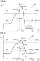
In einer bevorzugten Ausführungsform erfolgt die Unterscheidung zwischen der ersten Drucksituation und der zweiten Drucksituation auf Basis des ersten Messwertes und des zweiten Messwertes derart, dass zu einem ersten Zeitpunkt (
Sofern das gebildete Verhältnis (
Sofern das gebildete Verhältnis (
Der Vergleichswert (


Der zweite Zeitpunkt
Die nachfolgende Tabelle 4 zeigt für eine typische Atemfrequenz (RR, respiratory rate) von 12 Atemzyklen je Minute eines erwachsenen Menschen [RR= 12 min-1] bei einem typischen Inspirations- zu Exspirationsverhältnis (I:E-Ratio) von 1 zu 2 [I:E-Ratio = ½] beispielhafte typische Werte für
In einer weiter bevorzugten Ausführungsform erfolgt die Unterscheidung zwischen der ersten Drucksituation und der zweiten Drucksituation auf Basis des ersten Messwertes und des zweiten Messwertes derart, dass innerhalb der Beobachtungszeitdauer (
Anschließend wird aus dem ersten Messwert des Atemwegsdrucks (
Der dritte Zeitpunkt
Die Abschätzung des dritten Wert des Atemwegsdrucks (P3_estimate) zum dritten Zeitpunkt (
The estimation of the third value of the airway pressure (P3_estimate ) at the third time point (
Die nachfolgend angeführten Formeln 4 bis 6 beschreiben den Vergleich zur Unterscheidung zwischen der ersten und zweiten Drucksituation mit Hilfe der Abschätzung des Atemwegsdrucks (P3_estimate) zum dritten Zeitpunkt (


Die nachfolgende Tabelle 5 zeigt für eine typische Atemfrequenz (RR, respiratory rate) von 12 Atemzyklen je Minute eines erwachsenen Menschen [RR= 12 min-1] bei einem typischen Inspirations- zu Exspirationsverhältnis (I:E-Ratio) von 1 zu 2 [I:E-Ratio = ½] typische Werte für
In einer weiter bevorzugten Ausführungsform erfolgt die Unterscheidung zwischen der ersten Drucksituation und der zweiten Drucksituation auf Basis des ersten Messwertes und des zweiten Messwertes derart, dass innerhalb der Beobachtungszeitdauer (
Die nachfolgend angeführten Formeln 7 bis 9 beschreiben den Vergleich zur Unterscheidung zwischen der ersten und zweiten Drucksituation mit Hilfe der Abschätzung des Druck-Zeitprodukts (


Für Ausgestaltungen und Ausführungsformen zur Erfassung des Drucks im Atemsystem, bzw. des Atemwegdrucks
In einer besonderen Ausführungsform der Beatmungsvorrichtung wird der Druck im Atemsystem, bzw. des Atemwegdruck
In einer besonderen Ausführungsform der Beatmungsvorrichtung wird der wird der Druck im Atemsystem, bzw. des Atemwegdruck
In einer besonderen Ausführungsform der Beatmungsvorrichtung ist der Drucksensor als ein Messfühler nach einem Messprinzip eines Kolbenmanometers oder einer Druckwaage, eines Kompressions-Flüssigkeits-Manometers, einer Feder-Manometer, eines piezoelektrischen Messelements oder eines Dehnungs-Messelements ausgebildet.In a particular embodiment of the respiratory device, the pressure sensor is designed as a measuring sensor according to a measuring principle of a piston manometer or a pressure balance, a compression-liquid manometer, a spring-pressure gauge, a piezoelectric measuring element or a strain-measuring element.
Die beschriebenen Ausführungsformen stellen jeweils für sich, wie auch in Kombination oder Kombinationen miteinander besondere Ausgestaltungen der erfindungsgemäßen Beatmungsvorrichtung dar. Dabei sind auch sämtliche und mögliche durch Kombination oder Kombinationen mehrerer Ausführungsformen ergebende weitere Ausführungsformen und deren Vorteile gleichwohl vom Erfindungsgedanken mit erfasst, wenn auch nicht sämtliche Kombinationsmöglichkeiten von Ausführungsformen dazu im Detail jeweils ausgeführt sind.The embodiments described in each case constitute, as well as in combination or combinations with each other, special embodiments of the respiratory device according to the invention. All other possible embodiments and their advantages resulting from combinations or combinations of several embodiments are nevertheless also covered by the inventive concept, although not all Combination possibilities of embodiments thereof are executed in detail in each case.
Die vorliegende Erfindung wird nun mit Hilfe der folgenden Figuren und den zugehörigen Figurenbeschreibungen ohne Beschränkungen des allgemeinen Erfindungsgedankens näher erläutert. Es zeigen:
1 eine schematische Darstellung einer Beatmungsvorrichtung mit einem Sicherheitsventil,2 eine Darstellung einer Kontrolleinheit in der Beatmungsvorrichtung mit dem Sicherheitsventil,3a eine schematische Darstellung einer Drucksituation mit einer Aktivierung des Sicherheitsventils,3b eine schematische Darstellung einer Drucksituation ohne eine Aktivierung des Sicherheitsventils.
1 a schematic representation of a ventilation device with a safety valve,2 an illustration of a control unit in the ventilation device with the safety valve,3a a schematic representation of a pressure situation with an activation of the safety valve,3b a schematic representation of a pressure situation without activation of the safety valve.
Die
Alternativ zum Endo-Tracheal-Tubus können auch nicht-invasive Elemente zur Patientengaszuführung
Stromabwärts der Gasförderungs- und Dosiereinheit
Bei einer Druckerhöhung im pneumatischen Verbindungsystem
Die zweite Drucksituation
Im Falle, dass die zweite Drucksituation
In alternativen und besonderen und, an die Anwendung speziell angepassten Ausgestaltungen von Beatmungsgeräten
Solche Ausgestaltungen sind vom Gedanken der Erfindung mit umfasst, jedoch aus Gründen einer vereinfachten Darstellung und aus Gründen der Übersichtlichkeit nicht mit dargestellt. Die Messorte
Die
Das Sicherheitsventil
Mittels der Abschätzung führt das Überwachungsmodul
Dabei ist die erste Drucksituation
Dabei ist die zweite Drucksituation
Die Aktivierung des Sicherheitsventils
Die
Die
Die
Das Sicherheitsventil
BezugszeichenlisteLIST OF REFERENCE NUMBERS
- 11
- Medizingeräteanordnung, BeatmungsgerätMedical device assembly, respirator
- 33
- Patientpatient
- 55
- Patientengaszuführungsleitung (pneumatisches Verbindungssystem)Patient gas supply line (pneumatic connection system)
- 66
- Umgebung, AtmosphäreEnvironment, atmosphere
- 77
- Inspirationszweig (pneumatisches Verbindungssystem)Inspection branch (pneumatic connection system)
- 99
- Exspirationszweig (pneumatisches Verbindungssystem)Expiratory branch (pneumatic connection system)
- 1010
- Atemsystemrespiratory system
- 1111
- Messort der Patientendurchflussmenge, Y-Stück, VerbindungselementPlace of measurement of patient flow rate, Y-piece, connection element
- 1313
- Messort für Patientendruck, AtemwegsdruckLocation for patient pressure, airway pressure
- 1515
- Messort der inspiratorischen DurchflussmengePlace of measurement of the inspiratory flow rate
- 1717
- Messort der exspiratorischen DurchflussmengeSite of the expiratory flow rate
- 1919
- inspiratorischer Druck, Messortinspiratory pressure, location
- 2121
- exspiratorischer Druck, Messortexpiratory pressure, site
- 2323
- Gasförderungs- und DosiereinheitGas conveying and dosing unit
- 2424
- Sicherheitsventilsafety valve
- 2525
- Inspirationsventilinspiration valve
- 2626
- Exspirationsventilexpiratory
- 2727
- Kontrolleinheit, elektronische SteuerungControl unit, electronic control
- 2828
- Rückschlagventilecheck valves
- 2929
- Prozessoreinheitprocessor unit
- 3131
- DatenspeichereinheitData storage unit
- 4040
- Alarmierungseinheit, AlarmausgabeAlarm unit, alarm output
- 4141
- optisches Signalgabeelementoptical signaling element
- 4242
- akustisches Signalgabeelementacoustic signaling element
- 4343
- Eingabeeinheitinput unit
- 63, 67, 6963, 67, 69
- Signal-/Datenleitungen der DruckmessorteSignal / data lines of the pressure measuring points
- 83, 87, 89 83, 87, 89
- Signal-/Datenleitungen der Durchfluss-MessorteSignal / data lines of the flow measuring locations
- 9090
- Daten-/ SteuerleitungenData / control lines
- 9595
- Beatmungsbetrieb, GesamtfunktionVentilation mode, overall function
- 9797
- DurchflussmesswerteFlow measurements
- 9898
- Steuersignale zur Aktivierung / DeaktivierungControl signals for activation / deactivation
- 9999
- Messwerte des Drucks, DruckmesswerteMeasured values of pressure, pressure readings
- 150150
- Außerhalb des Gerätes angeordnete KomponentenComponents arranged outside the device
- 160160
- Innerhalb des Gerätes angeordnete KomponentenComponents arranged inside the device
- 181, 182, 183181, 182, 183
- Zeitpunkte
t1 ,t2 , ...t3 der Messwerterfassung307 timingst1 .t2 , ...t3 the measuredvalue acquisition 307 - 181', 182', 183'181 ', 182', 183 '
- Zeitpunkte
t1' ,t2' , ...t3' der Messwerterfassung307' timingst1 ' .t2 ' , ...t3 ' the measured value acquisition307 ' - 187187
- Beobachtungszeitdauer
twatch Period of observationtwatch - 188188
- zweiter Druckschwellenwert
PM second pressure thresholdPM - 189189
- erste Drucksituationfirst pressure situation
- 190190
- zweite Drucksituationsecond pressure situation
- 191, 192, 193191, 192, 193
- Druckmesswerte
P1 ,P2 , ...P3 zu Zeitpunktent1 ,t2 , ...t3 der Messwerterfassung307 Pressure readingsP1 .P2 , ...P3 at timest1 .t2 , ...t3 the measuredvalue acquisition 307 - 191', 192', 193'191 ', 192', 193 '
- Druckmesswerte
P1' ,P2' , ...P3' zu Zeitpunktent1' ,t2' , ...t3' der Messwerterfassung307' Pressure readingsP1 ' .P2 ' , ...P3 ' at timest1 ' .t2 ' , ...t3 ' the measured value acquisition307 ' - 255255
- Menge an AtemgasAmount of breathing gas
- 271271
- Regelungsmodulcontrol module
- 272272
- Messmodulmeasurement module
- 273273
- Überwachungsmodulmonitoring module
- 274274
- erstes Vergleichskriterium, erster Druckschwellenwert
Px first comparison criterion, first pressure thresholdpx - 274'274 '
- Zeitdauer Tx, zugehörig zum ersten DruckschwellenwertTime Tx associated with the first pressure threshold
- 275275
- zweites Vergleichskriteriumsecond comparison criterion
- 301301
- Druck-/ Zeitverlauf mit Aktivierung des SicherheitsventilsPressure / time curve with activation of the safety valve
- 303303
- Druck-/ Zeitverlauf ohne Aktivierung des SicherheitsventilsPressure / time curve without activation of the safety valve
- 305, 305'305, 305 '
- Ordinate mit Werten, Schwellenwerten des DrucksOrdinate with values, thresholds of pressure
- 307, 307'307, 307 '
- Abszisse mit Zeitverlauf und ZeitpunktenAbscissa with time and times
- 308, 308'308, 308 '
- Trendabschätzung (erste Drucksituation
189 )Trend estimation (first pressure situation189 ) - 309, 309'309, 309 '
- Trendabschätzung (zweite Drucksituation
190 )Trend estimation (second pressure situation190 )
ZITATE ENTHALTEN IN DER BESCHREIBUNG QUOTES INCLUDE IN THE DESCRIPTION
Diese Liste der vom Anmelder aufgeführten Dokumente wurde automatisiert erzeugt und ist ausschließlich zur besseren Information des Lesers aufgenommen. Die Liste ist nicht Bestandteil der deutschen Patent- bzw. Gebrauchsmusteranmeldung. Das DPMA übernimmt keinerlei Haftung für etwaige Fehler oder Auslassungen.This list of the documents listed by the applicant has been generated automatically and is included solely for the better information of the reader. The list is not part of the German patent or utility model application. The DPMA assumes no liability for any errors or omissions.
Zitierte PatentliteraturCited patent literature
- US 2904035 [0001]US 2904035 [0001]
- US 5400777 [0001]US 5400777 [0001]
- US 5937853 [0001]US 5937853 [0001]
- WO 2007/085110 A1 [0001]WO 2007/085110 A1 [0001]
- US 7882835 B2 [0001, 0002]US 7882835 B2 [0001, 0002]
- WO 2008/098382 A1 [0003]WO 2008/098382 A1 [0003]
- US 6571792 [0003]US 6571792 [0003]
- US 6553990 [0003]US 6553990 [0003]
- US 5596984 A [0005]US 5596984 A [0005]
- US 2007181125 AA [0006]US 2007181125 AA [0006]
Claims (10)
Translated fromGermanPriority Applications (1)
| Application Number | Priority Date | Filing Date | Title |
|---|---|---|---|
| DE102018003026.2ADE102018003026A1 (en) | 2018-04-13 | 2018-04-13 | Ventilation device with a safety valve |
Applications Claiming Priority (1)
| Application Number | Priority Date | Filing Date | Title |
|---|---|---|---|
| DE102018003026.2ADE102018003026A1 (en) | 2018-04-13 | 2018-04-13 | Ventilation device with a safety valve |
Publications (1)
| Publication Number | Publication Date |
|---|---|
| DE102018003026A1true DE102018003026A1 (en) | 2019-10-17 |
Family
ID=68052892
Family Applications (1)
| Application Number | Title | Priority Date | Filing Date |
|---|---|---|---|
| DE102018003026.2APendingDE102018003026A1 (en) | 2018-04-13 | 2018-04-13 | Ventilation device with a safety valve |
Country Status (1)
| Country | Link |
|---|---|
| DE (1) | DE102018003026A1 (en) |
Cited By (5)
| Publication number | Priority date | Publication date | Assignee | Title |
|---|---|---|---|---|
| DE102019120541A1 (en)* | 2019-07-30 | 2021-02-04 | Hamilton Medical Ag | System for regulating a ventilation variable of a ventilator, ventilator and method for regulating a ventilation variable of a ventilator |
| CN113350637A (en)* | 2020-03-06 | 2021-09-07 | 德尔格制造股份两合公司 | Breathing apparatus |
| DE102021113642A1 (en) | 2020-05-29 | 2021-12-02 | Drägerwerk AG & Co. KGaA | Connection arrangement with a volume flow sensor and a homogenization unit for artificial ventilation of a patient and a manufacturing method |
| CN115227924A (en)* | 2021-04-23 | 2022-10-25 | 德尔格制造股份两合公司 | Ventilators for mechanically administering artificial respiration to patients |
| CN118593847A (en)* | 2024-06-14 | 2024-09-06 | 广州蓝仕威克医疗科技有限公司 | A gas circuit design method, gas circuit structure and device for emergency transport ventilator |
Citations (13)
| Publication number | Priority date | Publication date | Assignee | Title |
|---|---|---|---|---|
| US2904035A (en) | 1957-01-29 | 1959-09-15 | Air Shields | Control apparatus for lung ventilators |
| US5400777A (en) | 1990-10-31 | 1995-03-28 | Siemens Aktiengesellschaft | Ventilator |
| US5596984A (en) | 1994-09-12 | 1997-01-28 | Puritan-Bennett Corporation | Lung ventilator safety circuit |
| US5937853A (en) | 1995-11-16 | 1999-08-17 | Siemens Elema Ab | Ventilator for respiratory treatment |
| US6553990B2 (en) | 2000-08-22 | 2003-04-29 | DRäGER MEDIZINTECHNIK GMBH | Process for changing the concentration in an anesthesia apparatus |
| US6571792B1 (en) | 1997-10-15 | 2003-06-03 | Datex-Ohmeda, Inc. | Smart modular anesthesia respiratory system |
| WO2007085110A1 (en) | 2006-01-30 | 2007-08-02 | Hamilton Medical Ag | O2-controller |
| US20070181125A1 (en) | 2005-04-28 | 2007-08-09 | Mulier Jan P | ventilator safety valve |
| WO2008098382A1 (en) | 2007-02-15 | 2008-08-21 | Hamilton Medical Ag | Blower for a medical ventilator and medical ventilator with such a blower |
| EP2066412A2 (en)* | 2006-09-11 | 2009-06-10 | RIC Investments, LLC. | Detecting ventilator system anomalies while in a speaking mode |
| US7882835B2 (en) | 2005-12-22 | 2011-02-08 | Dräger Medical GmbH | Device and method for determining leaks of a respirator |
| US20140053840A1 (en)* | 2011-12-30 | 2014-02-27 | Beijing Aeonmed Co., Ltd. | Human-Machine Synchronization Method And Device Of Invasive Ventilator Operating In Noninvasive Ventilation Mode |
| DE102016007336A1 (en)* | 2016-06-16 | 2017-12-21 | Drägerwerk AG & Co. KGaA | Medical device and method for alarm organization |
- 2018
- 2018-04-13DEDE102018003026.2Apatent/DE102018003026A1/enactivePending
Patent Citations (14)
| Publication number | Priority date | Publication date | Assignee | Title |
|---|---|---|---|---|
| US2904035A (en) | 1957-01-29 | 1959-09-15 | Air Shields | Control apparatus for lung ventilators |
| US5400777A (en) | 1990-10-31 | 1995-03-28 | Siemens Aktiengesellschaft | Ventilator |
| US5596984A (en) | 1994-09-12 | 1997-01-28 | Puritan-Bennett Corporation | Lung ventilator safety circuit |
| US5937853A (en) | 1995-11-16 | 1999-08-17 | Siemens Elema Ab | Ventilator for respiratory treatment |
| US6571792B1 (en) | 1997-10-15 | 2003-06-03 | Datex-Ohmeda, Inc. | Smart modular anesthesia respiratory system |
| US6553990B2 (en) | 2000-08-22 | 2003-04-29 | DRäGER MEDIZINTECHNIK GMBH | Process for changing the concentration in an anesthesia apparatus |
| US20070181125A1 (en) | 2005-04-28 | 2007-08-09 | Mulier Jan P | ventilator safety valve |
| US7882835B2 (en) | 2005-12-22 | 2011-02-08 | Dräger Medical GmbH | Device and method for determining leaks of a respirator |
| WO2007085110A1 (en) | 2006-01-30 | 2007-08-02 | Hamilton Medical Ag | O2-controller |
| EP2066412A2 (en)* | 2006-09-11 | 2009-06-10 | RIC Investments, LLC. | Detecting ventilator system anomalies while in a speaking mode |
| EP2066412B1 (en) | 2006-09-11 | 2016-11-16 | RIC Investments, LLC. | Detecting ventilator system anomalies while in a speaking mode |
| WO2008098382A1 (en) | 2007-02-15 | 2008-08-21 | Hamilton Medical Ag | Blower for a medical ventilator and medical ventilator with such a blower |
| US20140053840A1 (en)* | 2011-12-30 | 2014-02-27 | Beijing Aeonmed Co., Ltd. | Human-Machine Synchronization Method And Device Of Invasive Ventilator Operating In Noninvasive Ventilation Mode |
| DE102016007336A1 (en)* | 2016-06-16 | 2017-12-21 | Drägerwerk AG & Co. KGaA | Medical device and method for alarm organization |
Cited By (8)
| Publication number | Priority date | Publication date | Assignee | Title |
|---|---|---|---|---|
| DE102019120541A1 (en)* | 2019-07-30 | 2021-02-04 | Hamilton Medical Ag | System for regulating a ventilation variable of a ventilator, ventilator and method for regulating a ventilation variable of a ventilator |
| CN113350637A (en)* | 2020-03-06 | 2021-09-07 | 德尔格制造股份两合公司 | Breathing apparatus |
| US11925757B2 (en) | 2020-03-06 | 2024-03-12 | Drägerwerk AG & Co. KGaA | Ventilator |
| CN113350637B (en)* | 2020-03-06 | 2024-04-12 | 德尔格制造股份两合公司 | Breathing apparatus |
| DE102021113642A1 (en) | 2020-05-29 | 2021-12-02 | Drägerwerk AG & Co. KGaA | Connection arrangement with a volume flow sensor and a homogenization unit for artificial ventilation of a patient and a manufacturing method |
| US12409293B2 (en) | 2020-05-29 | 2025-09-09 | Drägerwerk AG & Co. KGaA | Connection with a volume flow sensor and a homogenization unit for artificial ventilation of a patient and manufacturing process |
| CN115227924A (en)* | 2021-04-23 | 2022-10-25 | 德尔格制造股份两合公司 | Ventilators for mechanically administering artificial respiration to patients |
| CN118593847A (en)* | 2024-06-14 | 2024-09-06 | 广州蓝仕威克医疗科技有限公司 | A gas circuit design method, gas circuit structure and device for emergency transport ventilator |
Similar Documents
| Publication | Publication Date | Title |
|---|---|---|
| DE102018003026A1 (en) | Ventilation device with a safety valve | |
| EP2298399B1 (en) | Anaesthetic device and method for operating same | |
| EP3653248B1 (en) | Respirators | |
| DE2927839A1 (en) | VENTILATOR | |
| WO2005075013A1 (en) | Respiratory device and method for controlling a respiratory device | |
| EP3903863B1 (en) | Method and device for detecting a leak in a ventilation circuit | |
| EP3156091B1 (en) | Device for monitoring a disconnection | |
| EP3536369B1 (en) | Respiratory apparatus with switching valve | |
| DE102007011924A1 (en) | Method and device for controlling a ventilator | |
| DE102007039004A1 (en) | Respiration parameter e.g. respiratory flow increase, capturing method for e.g. bi-level respirator assistance device, involves measuring respiratory gas flow, respiratory gas pressure, oxygen saturation or their combination as state value | |
| DE102016013140A1 (en) | A respiratory apparatus and method of operation for a ventilator with a determination of coughing attacks | |
| DE102016012824A1 (en) | Method and apparatus for adaptively controlling positive end-expiratory pressure (PEEP) | |
| DE102016013138B4 (en) | Medical device and method for determining operating situations in a medical device | |
| DE102016007336B4 (en) | Medical device and method for organizing alarms | |
| EP2989978A1 (en) | Artificial respiration device and method for same | |
| DE102010030324A1 (en) | Ventilation aid, ventilator, system and method for non-invasive ventilation of premature babies | |
| DE102018003027A1 (en) | breathing device | |
| EP3957347B1 (en) | Ventilator for high-flow oxygen therapy | |
| DE102007054390A1 (en) | Rebreathing gas portion determining method for use in respiration gas supply system, involves determining expiration and leakage volumes, and determining difference between expiration and leakage volumes as rebreathing portion | |
| EP4349388B1 (en) | Apparatus and method for detecting a leak during artificial respiration | |
| DE602004003409T2 (en) | Device for the determination of suction flow and suction time and for the extraction of dead space | |
| EP3964253B1 (en) | Computer program and device for automatically determining the target frequency of a breathing apparatus | |
| EP3524306B1 (en) | Artificial respiration device and test method | |
| DE102018008495A1 (en) | Valve module for a ventilation system, ventilation hose device, ventilation device, ventilation system and method for separating and establishing a fluid-communicating connection | |
| EP4238601B1 (en) | Apparatus for controlling gas flow |
Legal Events
| Date | Code | Title | Description |
|---|---|---|---|
| R163 | Identified publications notified | ||
| R012 | Request for examination validly filed | ||
| R084 | Declaration of willingness to licence |