DE102018000060A1 - Furniture with door hinged on both sides - Google Patents
Furniture with door hinged on both sidesDownload PDFInfo
- Publication number
- DE102018000060A1 DE102018000060A1DE102018000060.6ADE102018000060ADE102018000060A1DE 102018000060 A1DE102018000060 A1DE 102018000060A1DE 102018000060 ADE102018000060 ADE 102018000060ADE 102018000060 A1DE102018000060 A1DE 102018000060A1
- Authority
- DE
- Germany
- Prior art keywords
- pivoting
- holding
- axle
- furniture
- pivot
- Prior art date
- Legal status (The legal status is an assumption and is not a legal conclusion. Google has not performed a legal analysis and makes no representation as to the accuracy of the status listed.)
- Withdrawn
Links
- 238000010276constructionMethods0.000claimsdescription3
- 238000003860storageMethods0.000description8
- 238000003780insertionMethods0.000description5
- 230000037431insertionEffects0.000description5
- 230000007246mechanismEffects0.000description4
- 239000011324beadSubstances0.000description3
- 238000004519manufacturing processMethods0.000description2
- BUHVIAUBTBOHAG-FOYDDCNASA-N(2r,3r,4s,5r)-2-[6-[[2-(3,5-dimethoxyphenyl)-2-(2-methylphenyl)ethyl]amino]purin-9-yl]-5-(hydroxymethyl)oxolane-3,4-diolChemical compoundCOC1=CC(OC)=CC(C(CNC=2C=3N=CN(C=3N=CN=2)[C@H]2[C@@H]([C@H](O)[C@@H](CO)O2)O)C=2C(=CC=CC=2)C)=C1BUHVIAUBTBOHAG-FOYDDCNASA-N0.000description1
- 230000006978adaptationEffects0.000description1
- 238000005520cutting processMethods0.000description1
- 230000001419dependent effectEffects0.000description1
- 230000003993interactionEffects0.000description1
- 239000002184metalSubstances0.000description1
- 230000000284resting effectEffects0.000description1
- 238000007789sealingMethods0.000description1
- 238000007493shaping processMethods0.000description1
Images

Classifications
- E—FIXED CONSTRUCTIONS
- E05—LOCKS; KEYS; WINDOW OR DOOR FITTINGS; SAFES
- E05D—HINGES OR SUSPENSION DEVICES FOR DOORS, WINDOWS OR WINGS
- E05D7/00—Hinges or pivots of special construction
- E05D7/02—Hinges or pivots of special construction for use on the right-hand as well as the left-hand side; Convertible right-hand or left-hand hinges
- E—FIXED CONSTRUCTIONS
- E05—LOCKS; KEYS; WINDOW OR DOOR FITTINGS; SAFES
- E05D—HINGES OR SUSPENSION DEVICES FOR DOORS, WINDOWS OR WINGS
- E05D15/00—Suspension arrangements for wings
- E05D15/48—Suspension arrangements for wings allowing alternative movements
- E05D15/50—Suspension arrangements for wings allowing alternative movements for opening at either of two opposite edges
- E05D15/505—Suspension arrangements for wings allowing alternative movements for opening at either of two opposite edges by radial separation of the hinge parts at the hinge axis
- E—FIXED CONSTRUCTIONS
- E05—LOCKS; KEYS; WINDOW OR DOOR FITTINGS; SAFES
- E05Y—INDEXING SCHEME ASSOCIATED WITH SUBCLASSES E05D AND E05F, RELATING TO CONSTRUCTION ELEMENTS, ELECTRIC CONTROL, POWER SUPPLY, POWER SIGNAL OR TRANSMISSION, USER INTERFACES, MOUNTING OR COUPLING, DETAILS, ACCESSORIES, AUXILIARY OPERATIONS NOT OTHERWISE PROVIDED FOR, APPLICATION THEREOF
- E05Y2900/00—Application of doors, windows, wings or fittings thereof
- E05Y2900/20—Application of doors, windows, wings or fittings thereof for furniture, e.g. cabinets
Landscapes
- Engineering & Computer Science (AREA)
- Mechanical Engineering (AREA)
- Hinges (AREA)
- Wing Frames And Configurations (AREA)
Abstract
Translated fromGermanDescription
Translated fromGermanDie Erfindung betrifft ein Möbel mit einem ersten Gerätebauteil, beispielsweise einer Tür, und einem zweiten Gerätebauteil, beispielsweise einem Korpus, wobei das erste Gerätebauteil mittels einer Schwenkvorrichtung schwenkbar an dem zweiten Gerätebauteil angebracht ist und durch die Schwenkvorrichtung relativ zu dem zweiten Gerätebauteil um eine erste Schwenkachse und eine von der ersten verschiedene zweite Schwenkachse verschwenkbar gelagert ist, wobei jeder Schwenkachse zumindest ein an dem ersten Gerätebauteil angebrachtes Achselement zugeordnet ist, welches drehbar in der Schwenkvorrichtung gelagert ist.The invention relates to a piece of furniture with a first appliance component, for example a door, and a second appliance component, for example a carcass, wherein the first appliance component is pivotally attached to the second appliance component by means of a pivoting device and by the pivoting device relative to the second appliance component about a first pivot axis and one of the first different second pivot axis is pivotally mounted, wherein each pivot axis is associated with at least one attached to the first device component axle element, which is rotatably mounted in the pivoting device.
Es sind Möbel, gerade Schränke, bekannt, deren Tür beidseitig angeschlagen ist, sodass sich das Möbel, beispielsweise der Schrank, in zwei unterschiedliche Richtungen öffnen lässt. So lässt sich beispielsweise eine Schranktür durch eine vor ihr stehende Bedienperson von dieser aus betrachtet nach links und alternativ nach rechts öffnen oder aufschwenken. Damit soll beispielsweise bei beengten Raumverhältnissen ein flexibler Zugang zu dem Inhalt des Möbels erreicht werden, oder bestimmte Bereiche im Inneren des Möbels leichter zugänglich sein.There are furniture, just cabinets, known, the door is hinged on both sides, so that the furniture, such as the cabinet, can be opened in two different directions. Thus, for example, a cabinet door can be opened by an operator standing in front of her and viewed from this point open to the left or alternatively to the right or swing open. This is to be achieved, for example, in confined spaces a flexible access to the content of the furniture, or be more easily accessible areas inside the furniture.
Derartige Mechanismen sind bereits aus einer Reihe von Patenschriften, beispielsweise der
Es stellt sich somit die Aufgabe ein Möbel mit beidseitig angeschlagener Tür und vereinfachter Scharnier- oder Schwenkvorrichtung bereitzustellen.It thus sets itself the task to provide furniture with double-hinged door and simplified hinge or pivoting device.
Diese Aufgabe wird durch den Gegenstand des unabhängigen Patentanspruchs gelöst. Vorteilhafte Ausführungsformen und weitere Aspekte der Erfindung ergeben sich aus den abhängigen Patentansprüchen, der Beschreibung und den Figuren.This object is solved by the subject matter of the independent claim. Advantageous embodiments and further aspects of the invention will become apparent from the dependent claims, the description and the figures.
Ein Aspekt der Erfindung betrifft ein Möbel mit einem ersten Gerätebauteil und einem zweiten Gerätebauteil, wobei das erste Gerätebauteil bevorzugt eine Gerätetür oder ein Gerätekorpus ist und das zweite Gerätebauteil umgekehrt ein Gerätekorpus oder eine Gerätetür. Wenn also das erste Gerätebauteil eine Gerätetür ist, so ist das zweite Gerätebauteil ein Gerätekorpus; ist das erste Gerätebauteil der Gerätekorpus, so ist das zweite Gerätebauteil die Gerätetür. Dies liegt darin begründet, dass die im Folgenden erklärte Schwenkvorrichtung, welche synonym auch als Scharnier oder Scharniervorrichtung bezeichnet werden kann, auch invers, also umgekehrt genutzt werden kann um das zweite Gerätebauteil relativ zu dem ersten Gerätebauteil zu verschwenken.One aspect of the invention relates to a piece of furniture with a first device component and a second device component, wherein the first device component is preferably a device door or a device body, and the second device component is, conversely, a device body or a device door. Thus, if the first device component is a device door, then the second device component is a device body; If the first device component is the device body, then the second device component is the device door. This is due to the fact that the swivel device explained below, which can also be referred to as a hinge or hinge device, can also be used inversely, ie vice versa, in order to pivot the second device component relative to the first device component.
Das erste Gerätebauteil ist dabei mittels der Schwenkvorrichtung schwenkbar an dem zweiten Gerätebauteil angebracht (im Sinne von befestigt) und relativ zu dem zweiten Gerätebauteil um eine erste Schwenkachse und um eine von der ersten verschiedene, bevorzugt parallel zu dieser verlaufende, zweite Schwenkachse verschwenkbar. Die beiden Gerätebauteile sind also durch die Schwenkvorrichtung aneinander befestigt um zwei unterschiedliche Schwenkachsen gegeneinander verschwenkbar. Dabei ist jeder Schwenkachse zumindest ein an dem ersten Gerätebauteil angebrachten Achselement, beispielsweise eine Welle oder ein Zapfen, zugeordnet. Das Achselement ist somit unabhängig von der Schwenkvorrichtung an dem ersten Gerätebauteil, beispielsweise der Gerätetür, angebracht. Der Begriff „zugeordnet“ kann hier so zu verstehen sein, dass das jeweilige Achselement bei einem Drehen oder Verschwenken des ersten Gerätebauteils um die zugeordnete Schwenkachse in dieser zugeordneten Schwenkachse verläuft, das heißt die Schwenkachse und die Achse des Achselements zusammenfallen. Dabei sind die Achselemente drehbar in der Schwenkvorrichtung gelagert. Beispielsweise kann sich somit bei einem Verschwenken um die erste Schwenkachse das erste Achselement in der Schwenkvorrichtung drehen. Wie weiter unten noch ausgeführt kann so bei einem Verschwenken um die erste Schwenkachse beispielsweise das erste Achselement gemeinsam mit dem unten beschriebenen ersten Schwenkarmelement der Schwenkvorrichtung in dem entsprechenden ersten Halteelement gedreht werden. Dabei kann das zweite Achselement in dem ersten Schwenkarmelement ruhend mit dem ersten Schwenkarmelement um die erste Schwenkachse verschwenkt werden. Bei einem Verschwenken um die zweite Schwenkachse statt um die erste Schwenkachse kann mutatis mutandis das Gleiche gelten.The first device component is pivotally mounted on the second device component (in the sense of attached) and pivotable relative to the second device component about a first pivot axis and about one of the first different, preferably parallel to this, extending second pivot axis. The two device components are thus secured by the pivoting device to each other about two different pivot axes against each other. In this case, each swivel axis is assigned at least one axle element attached to the first device component, for example a shaft or a journal. The axle is thus independent of the pivoting device on the first device component, such as the door, mounted. The term "assigned" here can be understood to mean that the respective axle element runs in this associated pivot axis when the first device component is rotated or pivoted about the associated pivot axis, that is to say coincide with the pivot axis and the axis of the shaft element. The axle elements are rotatably mounted in the pivoting device. For example, upon pivoting about the first pivot axis, the first axle element can thus rotate in the pivoting device. As will be explained further below, during pivoting about the first pivot axis, for example, the first axle element can be rotated together with the first pivot arm element of the pivoting device described below in the corresponding first retaining element. In this case, the second axle element can be pivoted in the first swivel arm element in a resting manner with the first swivel arm element about the first swivel axis. When pivoting about the second pivot axis instead of the first pivot axis mutatis mutandis the same applies.
Die Schwenkvorrichtung weist dabei zumindest eine erste und zumindest eine zweite Schwenkeinheit auf, wobei die erste Schwenkeinheit ein bevorzugt unbeweglich an dem zweiten Gerätebauteil, beispielsweise dem Gerätekorpus, angebrachtes erstes Halteelement sowie ein um die erste Schwenkachse verschwenkbar an dem ersten Halteelement angebrachtes oder gelagertes erstes Schwenkarmelement aufweist und die zweite Schwenkeinheit entsprechend ein bevorzugt unbeweglich an dem zweiten Gerätebauteil angebrachtes zweites Halteelement sowie ein um die zweite Schwenkachse verschwenkbar an dem zweiten Halteelement angebrachtes oder gelagertes zweites Schwenkarmelement aufweist. Die Schwenkvorrichtung kann beispielsweise auch zwei erste und zwei zweite Schwenkeinheiten aufweisen. Bevorzugt sind diese dann an gegenüberliegenden Bereichen der beiden Gerätebauteile angeordnet, beispielsweise eine erste und eine zweite Schwenkvorrichtung an einem oberen Randbereich des ersten und zweiten Gerätebauteils und eine weitere erste und eine weitere zweite Schwenkvorrichtung an einem unteren Randbereich des ersten und zweiten Gerätebauteils. Dies ist analog für einseitig angeschlagene Türen allgemein bekannt. Oberer und unterer Rand sind hier bevorzugt durch die Orientierung des Möbels im Schwerefeld der Erde bei bestimmungsgemäßem Gebrauch bestimmt.The swiveling device has at least one first and at least one second swiveling unit, the first swiveling unit having a first holding element mounted immovably on the second appliance component, for example the appliance body, and a first swiveling arm element mounted or mounted pivotably on the first holding element about the first swiveling axis and the second pivot unit corresponding to a second, preferably immovably attached to the second apparatus component Has holding element and a pivotable about the second pivot axis attached to the second holding element or mounted second Schwenkarmelement. The pivoting device may for example also have two first and two second pivoting units. These are then preferably arranged on opposite regions of the two device components, for example a first and a second pivoting device on an upper edge region of the first and second device component and a further first and a further second pivoting device on a lower edge region of the first and second device component. This is analogous generally known for one-sided hinged doors. Upper and lower edge are here preferably determined by the orientation of the furniture in the gravitational field of the earth when used as intended.
Dabei ist das der ersten Schwenkachse zugeordnete erste Achselement drehbar in dem zweiten Schwenkarmelement gelagert, beispielsweise in einem Loch des zweiten Schwenkarmelementes, und das der zweiten Schwenkachse zugeordnete zweite Achselement drehbar in dem ersten Schwenkarmeelement gelagert, beispielsweise wiederum in einem Loch. Dabei kann sich das jeweilige Achselement in oder durch das jeweilige Loch erstrecken.In this case, the first axis of rotation associated with the first axis element is rotatably mounted in the second Schwenkarmelement, for example in a hole of the second Schwenkarmelementes, and the second pivot axis associated second axis element rotatably mounted in the first pivot arm element, for example, again in a hole. In this case, the respective axle element may extend into or through the respective hole.
Das erste Achselement ist in einem Achsabschnitt, also in einem Abschnitt des Achselementes entlang einer Längs- oder Drehachse des Achselementes bereichsweise von dem ersten Halteelement und/oder dem ersten Schwenkarmelement umgriffen. Alternativ (beispielsweise bei einer Offenstellung von Gerätetür und Gerätekorpus) oder ergänzend (beispielsweise bei einer Geschlossenstellung von Gerätetür und Gerätekorpus) ist das zweite Achselement bereichsweise von dem zweiten Halteelement und/oder dem ersten Schwenkarmelement umgriffen. Unter einem bereichsweisen Umgreifen kann hier ein radial umlaufendes Umgreifen um einen vorgegebenen Teilwinkelbereich, beispielsweise einen Teilwinkelbereich von 150 Grad oder mehr, beispielsweise bevorzugt 180 Grad verstanden werden. Das erste und/oder zweite Achselement kann also in einem Achsabschnitt in einer Aussparung des ersten beziehungsweise zweiten Halte- und/oder Schwenkarmelements angeordnet sein.The first axle element is encompassed by an area of the first retaining element and / or the first pivot arm element in an axial section, that is to say in a section of the axle element along a longitudinal or rotational axis of the axle element. Alternatively (for example in the case of an open position of the appliance door and appliance body) or in addition (for example in a closed position of the appliance door and appliance body), the second axle element is encompassed in regions by the second holding element and / or the first pivot arm element. Under an area-wise encompassing can be understood here a radially encircling around a predetermined partial angle range, for example, a partial angle range of 150 degrees or more, for example, preferably 180 degrees. The first and / or second axle element can therefore be arranged in an axle section in a recess of the first or second holding and / or pivoting arm element.
In der Ebene, welche durch die beiden Schwenkachsen aufgespannt ist, sind das erste und das zweite Achselement, welche auch als linkes und rechtes Achselement bezeichnet werden können, dabei bevorzugt in einem ersten (aus Sicht eines Nutzers bei bestimmungsgemäßen Gebrauch linken) und zweiten (aus Sicht eines Nutzers bei bestimmungsgemäßen Gebrauch rechten) Randbereich des ersten Gerätebauteils, beispielsweise der Gerätetür, angeordnet, welche durch einen Mittelbereich voneinander getrennt sind. Jeder der Randbereiche kann dabei beispielsweise 20 Prozent oder weniger, bevorzugt 10 Prozent oder weniger des ersten Gerätebauteils in einer senkrecht zu den Schwenkachsen verlaufenden Quererstreckung einnehmen. Diese genannten Angaben beziehen sich hier auf das erste und zweite Gerätebauteil im unverschwenkten Zustand, sprich auf ein Möbel mit geschlossener Tür („Geschlossenstellung“). Analog lässt sich für das erste Gerätebauteil, beispielsweise die Gerätetür auch ein oberer und unterer Randbereich definieren. Dabei kann das Elektrogerät die beschriebene Schwenkvorrichtung in oder an einem oberen Randbereich der beiden Gerätebauteile oder in einem unteren Randbereich der beiden Gerätebauteile oder aber in beiden Randbereichen aufweisen, wie oben anhand der weiteren ersten und zweiten Schwenkeinheiten bereits beschrieben. Die Ausführung einer jeweiligen Schwenkvorrichtung im oberen und unteren (Tür- oder Korpus-) Randbereich führt dabei zu einem besonders zuverlässigen Halten der beiden Gerätebauteile aneinander, bei welchen bei dem Schwenken die beiden Gerätebauteile besonders präzise zueinander geführt werden.In the plane which is spanned by the two pivot axes, the first and the second axle element, which can also be referred to as left and right axle element, thereby preferably in a first (from the user's perspective when used as intended left) and second (off View of a user when used properly right) edge region of the first device component, such as the door, arranged, which are separated by a central region. Each of the edge regions can take, for example, 20 percent or less, preferably 10 percent or less, of the first device component in a transverse extension running perpendicular to the pivot axes. These specifications refer here to the first and second device component in the untwisted state, ie a piece of furniture with a closed door ("closed position"). Analogously, for the first device component, for example the appliance door, an upper and lower edge region can also be defined. In this case, the electrical device may have the described pivoting device in or on an upper edge region of the two device components or in a lower edge region of the two device components or in both edge regions, as already described above with reference to the further first and second pivoting units. The execution of a respective pivoting device in the upper and lower (door or carcass) edge region leads to a particularly reliable holding the two device components together, in which when pivoting the two device components are performed particularly precisely to each other.
Die beschriebene Ausführungsform hat mehrere Vorteile. Einerseits kommt die beschriebene Schwenkvorrichtung mit sehr wenigen Bauteilen aus. Da nämlich bereits bei einem gewöhnlichen Möbel üblicherweise ein unbeweglich an dem Gerätekorpus angebrachtes Halteelement sowie ein durch dieses Halteelement verlaufendes Achselement erforderlich ist, wird nun lediglich ein zweites Achselement, ein weiteres Halteelement sowie die beiden Schwenkarme benötigt. Weitere Federn, Zahnräder oder gar elektrische oder elektronische Steuerkomponenten sind nicht erforderlich. Durch das bereichsweise Umgreifen des Achselements durch das jeweilige Halte- und/oder Schwenkarmelement in Kombination mit der Führung des jeweiligen Achselements durch das Schwenkarmelement wird verhindert, dass die Tür sich in unerwünschter Weise anders als um die beiden Schwenkachsen relativ zu dem Gerätekorpus bewegt. Dabei werden die Schwenkarmelemente lediglich auf Zug belastet, sodass an sie besonders geringe mechanische Anforderungen gestellt sind.The described embodiment has several advantages. On the one hand, the pivoting device described comes out with very few components. Since an already immovably mounted on the device body holding element and an extending through this holding element axle element is usually required for an ordinary furniture, now only a second axle element, another holding element and the two pivot arms is required. Other springs, gears or even electrical or electronic control components are not required. By partially gripping the axle element by the respective holding and / or Schwenkarmelement in combination with the leadership of the respective axis element by the Schwenkarmelement prevents the door moves in an undesirable manner other than the two pivot axes relative to the device body. In this case, the Schwenkarmelemente are charged only to train, so they are placed on particularly low mechanical requirements.
Durch das bereichsweise Umgreifen der beiden Achselemente durch die jeweiligen Schwenkarmelemente, das heißt des ersten Achselementes durch das erste Schwenkarmelement und des zweiten Achselementes durch das zweite Schwenkarmelement, wird bei einem Verdrehen des ersten Gerätebauteils um die erste Schwenkachse auch das erste Schwenkarmelement gegenüber dem ersten Halteelement verdreht, sodass ein automatisches Verriegeln durchgeführt werden kann, welches eine -sichere Führung des ersten Achselementes in der ersten Schwenkachse durch das erste Halteelement und das hierzu verschwenkte erste Schwenkarmelement sicherstellt.As a result of the region-wise encompassing of the two axle elements by the respective pivot arm elements, that is to say the first axle element through the first pivot arm element and the second axle element through the second pivot arm element, the first pivot arm element is also rotated relative to the first retaining element when the first device component is rotated about the first pivot axis so that an automatic locking can be performed, which is a -secure leadership of the first axle in the first pivot axis through the first holding element and the pivoted first Schwenkarmelement ensures.
Die Achselemente können hier auch (zumindest dem von Halte- und/oder Schwenkarmelement umgriffenen Abschnitt) einen in einer Ebene senkrecht zu den Schwenkachsen nicht-runden Querschnitt aufweisen. Insbesondere kann der Querschnitt an eine Form der Aussparung in Halte- und/oder Schwenkarmelement angepasst sein. Insbesondere ist das erste Achselement in dem ersten Schwenkarmelement nicht-drehbar gelagert und relativ zum ersten Halteelement nur mit dem ersten Schwenkarmelement gemeinsam drehbar. Dies gilt mutatis mutandis für das zweite Achselement. Damit kann in verschwenktem Zustand („Offenstellung“) ein Spiel des ersten beziehungsweise zweiten Achselements in dem ersten beziehungsweise zweiten Halte- und/oder Schwenkarmelement reduziert oder minimiert werden.The axle elements may also have (at least the section encompassed by the holding and / or swivel arm element) a cross-section which is non-round in a plane perpendicular to the swivel axes. In particular, the cross section can be adapted to a shape of the recess in holding and / or Schwenkarmelement. In particular, the first axle element is non-rotatably mounted in the first pivot arm element and rotatable relative to the first retaining element only with the first pivot arm element together. This applies mutatis mutandis for the second axis. Thus, in the pivoted state ("open position") a play of the first or second axle element can be reduced or minimized in the first and second holding and / or Schwenkarmelement.
Dabei kann das erste Halteelement zugleich auch einen Bereich des ersten Schwenkarmelementes umgreifen. Zwischen dem von dem ersten Halteelement bereichsweise umgriffenen Achsabschnitt des ersten Achselementes und dem ersten Halteelement kann somit zumindest bereichsweise ein Teil des ersten Schwenkarmelementes angeordnet sein. Entsprechend kann dies mutatis mutandis alternativ oder ergänzend auch für das zweite Halte-, Achs- und Schwenkarmelement gelten.At the same time, the first retaining element can also encompass a region of the first pivoting arm element. Between the region of the first axle element engaged by the first holding element and the first holding element, a part of the first pivoting arm element can thus be arranged at least in regions. Accordingly, this mutatis mutandis alternatively or additionally apply to the second holding, axle and Schwenkarmelement.
In einer vorteilhaften Ausführungsform ist hier vorgesehen dass, insbesondere bei geschlossenem Möbel („Geschlossenstellung“), das erste Achselement senkrecht zu einem durch das erste Achselement verlaufenden Radius um die zweite Schwenkachse verschiebbar in dem ersten Schwenkarmelement und/oder dem ersten Halteelement, insbesondere auch drehbar, angeordnet oder gehalten ist. Insbesondere ist das erste Achselement dabei zumindest in einem Abschnitt (entlang der Längsachse des Achselements) in einer jeweiligen Aussparung des Halteelements und/oder des Schwenkarmelementes angeordnet oder gehalten. Der Aussparung kann ein jeweiliger erster Haltebereich des ersten Halteelements und/oder des ersten Schwenkarmelementes, beispielsweise U-förmiger oder C-förmiger Haltebereich, zugeordnet werden. Der Haltebereich des Halteelements kann dabei insbesondere ein C-förmiger Haltebereich sein, der Haltebereich des Schwenkarmelementes insbesondere ein U-förmiger Haltebereich. Das erste Achselement kann also von dem ersten Haltebereich (des ersten Halteelements und/oder des ersten Schwenkarmelements) bereichsweise umlaufend von dem ersten Halteelement und/oder dem ersten Schwenkarmelement umgriffen sein.In an advantageous embodiment, it is provided here that, in particular when the furniture is closed ("closed position"), the first axle element can be displaced perpendicularly to a radius extending through the first axle element about the second pivot axis in the first pivot arm element and / or the first retaining element, in particular also rotatably , arranged or held. In particular, the first axle element is arranged or held at least in one section (along the longitudinal axis of the axle element) in a respective recess of the retaining element and / or the pivoting arm element. The recess may be associated with a respective first holding region of the first holding element and / or of the first pivoting arm element, for example a U-shaped or C-shaped holding region. The holding region of the holding element may in particular be a C-shaped holding region, the holding region of the pivoting arm element in particular a U-shaped holding region. Thus, the first axle element can be encompassed circumferentially by the first retaining element and / or the first pivoting arm element in certain areas of the first retaining region (of the first retaining element and / or of the first pivoting arm element).
Alternativ oder ergänzend kann auch das zweite Achselement senkrecht zu einem durch das zweite Achselement verlaufenden Radius um die erste Schwenkachse verschiebbar in dem zweiten Schwenkarmelement und/oder dem zweiten Halteelement, insbesondere auch drehbar, angeordnet sein. Insbesondere ist das zweite Achselement dabei zumindest in einem Abschnitt (entlang der Längsachse des Achselements) in einer jeweiligen Aussparung des Halteelements und/oder des Schwenkarmelementes angeordnet oder gehalten. Der jeweiligen Aussparung kann ein jeweiliger zweiter Haltebereich des zweiten Halteelements und/oder des zweiten Schwenkarmelementes, beispielsweise U-förmiger oder C-förmiger Haltebereich, zugeordnet werden. Der Haltebereich des Halteelements kann dabei insbesondere ein C-förmiger Haltebereich sein, der Haltebereich des Schwenkarmelementes insbesondere ein U-förmiger Haltebereich. Das zweite Achselement kann also von dem zweiten Haltebereich (des zweiten Halteelements und/oder des zweiten Schwenkarmelements) bereichsweise umlaufend von dem zweiten Halteelement und/oder dem zweiten Schwenkarmelement umgriffen sein.Alternatively or additionally, the second axis element perpendicular to a radius extending through the second axis element about the first pivot axis slidably in the second Schwenkarmelement and / or the second holding element, in particular also rotatably arranged. In particular, the second axle element is arranged or held at least in one section (along the longitudinal axis of the axle element) in a respective recess of the retaining element and / or the pivoting arm element. The respective recess can be associated with a respective second holding region of the second holding element and / or the second pivoting arm element, for example a U-shaped or C-shaped holding region. The holding region of the holding element may in particular be a C-shaped holding region, the holding region of the pivoting arm element in particular a U-shaped holding region. Thus, the second axle element can be encompassed circumferentially by the second retaining element and / or the second pivot arm element by the second retaining region (of the second retaining element and / or of the second pivoting arm element).
Insbesondere sind hier die jeweils identischen Achsabschnitte von ersten oder zweiten Achselement durch erstes beziehungsweise zweites Halte- und Schwenkarmelement umgriffen. In diesem Fall ist also zumindest bereichsweise das jeweilige (erste oder zweite) Schwenkarmelement räumlich zwischen (ersten beziehungsweise zweiten) Achselement und (ersten oder zweiten) Halteelement angeordnet. Der insbesondere C- beziehungsweise U-förmige Haltebereich dient dabei jeweils dem Einführen des Achselementes senkrecht zur Längsachse des Achselements in den jeweiligen Haltebereich, der auch als Lagerbereich bezeichnet werden kann, aus einer durch die Öffnung des C beziehungsweise des U bestimmten Einführungsrichtung.In particular, the respectively identical shaft sections of the first or second axle element are encompassed by first and second holding and swivel arm elements. In this case, therefore, the respective (first or second) Schwenkarmelement is spatially arranged between (first or second) axis element and (first or second) holding element at least partially. The particular C- or U-shaped holding area serves in each case the insertion of the axle element perpendicular to the longitudinal axis of the axle element in the respective holding area, which can also be referred to as a storage area, from a certain through the opening of the C or U insertion direction.
Das hat den Vorteil, dass eine besonders zuverlässige Verriegelung des ersten Achselements bei Verschwenken um die erste Schwenkachse und des zweiten Achselementes bei Verschwenken um die zweite Schwenkachse erreicht wird. Dabei werden für das Verriegeln keinerlei zusätzliche Bauteile benötigt, vielmehr kann durch die entsprechende Formgebung der bereits vorhandenen Komponenten diese Funktion zuverlässig von den beschriebenen Elementen übernommen werden.This has the advantage that a particularly reliable locking of the first axle element is achieved when pivoting about the first pivot axis and the second axle element when pivoting about the second pivot axis. In this case, no additional components are required for locking, but this function can be reliably taken over by the described elements by the appropriate shaping of the existing components.
In einer weiteren vorteilhaften Ausführungsform ist vorgesehen, dass sich bei geschlossenem Möbel („Geschlossenstellung“), also bei weder um die erste noch um die zweite Schwenkachse gegeneinander verschwenkten ersten und zweiten Gerätebauteilen, die dem (insbesondere C-förmigen) Haltebereich des ersten Halteelements zugeordnete (erste) Aussparung des ersten Halteelements und die dem (insbesondere U-förmigen) Haltebereich des ersten Schwenkarmelements zugeordnete (erste) Aussparung des ersten Schwenkarmelements in einer Orthogonalprojektion auf eine senkrecht zur ersten Schwenkachse verlaufenden Ebene gleichorientiert überlappen, sodass bei einem Verschwenken der Gerätetür und damit des ersten Achselementes um die zweite Schwenkachse, also bei einem Öffnen der Gerätetür um die zweite Schwenkachse, das erste Achselement aus den (ersten) Aussparungen gleitet oder gleiten kann. Alternativ oder ergänzend kann in der Geschlossenstellung auch eine dem (insbesondere C-förmigen) zweiten Haltebereich des zweiten Halteelements zugeordnete (zweite) Aussparung des zweiten Halteelements und eine dem (insbesondere U-förmigen) zweiten Haltebereich des zweiten Schwenkarmelementes zugeordnete Aussparung des zweiten Schwenkarmelementes in einer Orthogonalprojektion auf eine senkrecht zur ersten oder zweiten Schwenkachse verlaufenden Ebene gleichorientiert überlappen, sodass bei einem Verschwenken der Gerätetür und damit des zweiten Achselementes um die erste Schwenkachse, also bei einem Öffnen der Gerätetür um die erste Schwenkachse das zweite Achselement aus den (zweiten) Aussparungen gleitet oder gleiten kann.In a further advantageous embodiment, it is provided that, when the furniture is closed ("closed position"), that is, neither the first nor the second pivot axis pivoted against each other first and second device components associated with the (in particular C-shaped) holding portion of the first support member (first) recess of the first holding element and the the (in particular U-shaped) holding region of the first Schwenkarmelements assigned ( first) recess of the first Schwenkarmelements in an orthogonal projection overlap equally oriented on a plane perpendicular to the first pivot axis, so that upon pivoting of the door and thus the first axis element about the second pivot axis, so when opening the door to the second pivot axis, the first axis element from the (first) recesses can slide or slide. Alternatively or additionally, in the closed position, a (second) recess of the second holding element associated with the second holding element and in particular a U-shaped second holding region of the second pivoting arm element can also be formed in a recess of the second pivoting arm element Orthogonalprojektion overlap equally oriented on a perpendicular to the first or second pivot axis extending plane, so that upon pivoting of the door and thus the second axis element about the first pivot axis, so when opening the door to the first pivot axis, the second axle element from the (second) recesses slides or can slide.
Das hat den Vorteil, dass sich die Tür des Möbels besonders leicht um beide Schwenkachsen gegenüber dem Gerätekorpus verschwenken lässt und dennoch eine zuverlässige Verriegelung erreicht werden kann.This has the advantage that the door of the furniture can be particularly easy to pivot about both pivot axes relative to the device body and yet a reliable locking can be achieved.
In einer weiteren vorteilhaften Ausführungsform ist vorgesehen, dass bei geöffnetem Möbel mit um die erste Schwenkachse verschwenktem Gerätebauteil („Offenstellung“) sich die dem ersten Haltebereich des ersten Halteelements zugeordnete Aussparung des ersten Halteelements und die dem ersten Haltebereich des ersten Schwenkarmelements zugeordnete Aussparung des ersten Schwenkarmelements in einer Orthogonalprojektion auf eine senkrecht zur ersten oder zweiten Schwenkachse verlaufenden Ebene verdreht überlappen, sodass das erste Achselement in den Aussparungen von erstem Halteelement und erstem Schwenkarmelement fixiert ist. Die Orientierung beziehungsweise Verdrehung der beiden Aussparungen wird dabei durch die Orientierung der durch die genaue Form der jeweiligen Aussparung bestimmten Einführungsrichtung des Achselementes in die jeweilige Aussparung vorgegeben. Sind die Aussparungen gleich orientiert, so verlaufen die beiden Einführungsrichtungen parallel und in die gleiche Richtung. Sind die Aussparungen verdreht, so verlaufen die Einführungsrichtungen soweit verdreht, dass sich das Achselement in der senkrecht zur Schwenkachse verlaufenden Ebene nicht mehr gleichzeitig in die beiden Aussparungen einführen lässt. Alternativ oder ergänzend ist dabei vorgesehen, dass bei geöffnetem Möbel mit um die zweite Schwenkachse verschwenkten Gerätebauteil („Offenstellung“) die dem zweiten Haltebereich des zweiten Halteelements zugeordnete Aussparung des zweiten Halteelements und die dem zweiten Haltebereich zugeordnete Aussparung des zweiten Schwenkarmelements in der Orthogonalprojektion auf die senkrecht zur ersten oder zweiten Schwenkachse verlaufenden Ebene verdreht überlappen, sodass das zweite Achselement in den beiden Aussparungen von zweitem Halteelement und zweitem Schwenkarmelement fixiert ist. Das Achselement kann also in der Ebene der Orthogonalprojektion nicht mehr aus diesen heraus oder in diese hineingeschoben werden.In a further advantageous embodiment, it is provided that, when the furniture is open, with the device component pivoted about the first pivot axis ("open position"), the recess of the first holding element associated with the first holding area of the first holding element and the recess of the first pivoting arm element associated with the first holding area of the first pivoting arm element overlap in an orthogonal projection twisted on a perpendicular to the first or second pivot axis extending plane, so that the first axle element is fixed in the recesses of the first holding member and the first Schwenkarmelement. The orientation or rotation of the two recesses is predetermined by the orientation of the specific shape of the respective recess specific insertion direction of the axle in the respective recess. If the recesses are oriented the same way, the two insertion directions are parallel and in the same direction. If the recesses are twisted, the insertion directions are twisted so far that the axle element in the plane perpendicular to the pivot axis can no longer be introduced simultaneously into the two recesses. Alternatively or additionally, it is provided that when the furniture is open with the device pivoted about the second pivot axis ("open position") the second holding area of the second holding element associated recess of the second holding element and the second holding area associated recess of the second Schwenkarmelements in the orthogonal projection on the overlap twisted perpendicular to the first or second pivot axis extending plane, so that the second axle element is fixed in the two recesses of the second holding element and the second Schwenkarmelement. The axis element can therefore no longer be pushed out of or into the plane of the orthogonal projection.
Das hat den Vorteil, dass auf besonders einfache Weise ein Verriegelungsmechanismus realisiert wird, welcher bei dem üblichen, dem bestimmungsgemäßen Gebrauch entsprechenden Öffnen und Schließen des Möbels betätigt wird, ohne dass hier weitere sich bewegende Teile erforderlich wären.This has the advantage that a locking mechanism is realized in a particularly simple manner, which is actuated in the usual, the intended use corresponding opening and closing of the furniture without further moving parts would be required here.
In einer weiteren vorteilhaften Ausführungsform ist vorgesehen, dass durch das erste Schwenkarmelement das zweite Achselement in einem konstanten, also bei bestimmungsgemäßen Gebrauch unveränderlichen, Abstand zu der ersten Schwenkachse gehalten wird und/oder durch das zweite Schwenkarmelement das erste Achselement in einem konstanten, also bei bestimmungsgemäßen Gebrauch unveränderlichen Abstand zu der zweiten Schwenkachse gehalten wird.In a further advantageous embodiment, it is provided that the second axle element is held by the first pivot arm element in a constant, ie intended use unchangeable distance to the first pivot axis and / or by the second Schwenkarmelement the first axis element in a constant, that is intended Use is held constant distance to the second pivot axis.
Das hat den Vorteil, dass bei geschlossener Gerätetür („Geschlossenstellung“) verhindert wird, dass die Tür sich anders als um eine der beiden Schwenkachsen schwenkend relativ zu dem Gerätekorpus bewegt, beispielsweise als Ganzes parallel zu der von den beiden Schwenkachsen aufgespannten Ebene von dem Korpus entfernt wird.This has the advantage that, when the door is closed ("closed position"), the door is prevented from pivoting relative to the device body, unlike one of the two pivot axes, for example as a whole parallel to the plane defined by the two pivot axes of the carcass Will get removed.
In einer weiteren vorteilhaften Ausführungsform ist vorgesehen, dass das erste Gerätebauteil eine Gerätetür und das zweite Gerätebauteil ein Gerätekörper ist oder umfasst. Alternativ kann vorgesehen sein, dass das erste Gerätebauteil ein Gerätekörper und das zweite Gerätebauteil eine Gerätetür ist oder umfasst.In a further advantageous embodiment, it is provided that the first device component is a device door and the second device component is or comprises a device body. Alternatively, it may be provided that the first device component is a device body and the second device component is or comprises a device door.
Das hat den Vorteil, dass das Möbel besonders ähnlich zu den bekannten Aufbauten ist, bei welchen im Allgemeinen ein Halte- oder Lagerelement fest an dem Gerätekorpus angeordnet ist und ein entsprechendes Achselement an der entsprechenden Gerätetür. Dies ist beispielsweise auch von Kühlschränken bekannt, bei welchen üblicherweise die Achselement in der Tür befestigt sind und die Halteelemente am Gerätekorpus. Daher kann so ein bestehender Herstellungsprozess mit wenig Aufwand an das vorgeschlagene Möbel angepasst werden.This has the advantage that the furniture is particularly similar to the known structures, in which in general a holding or bearing element is fixedly arranged on the device body and a corresponding axle element on the corresponding appliance door. This is for example also known from refrigerators, in which usually the axle are fixed in the door and the holding elements on the device body. Therefore, such an existing manufacturing process can be adapted to the proposed furniture with little effort.
In einer weiteren vorteilhaften Ausführungsform ist vorgesehen, dass die Schwenkeinheiten je baugleich sind. Das hat den Vorteil, dass der technische Aufbau weiter vereinfacht wird, da nur wenige Baugruppen erforderlich sind. So kann beispielsweise das Halteelement in einer einzigen, bevorzugt geschröpften, Bauform hergestellt und verbaut werden und entsprechend das Schwenkarmelement ebenso. Bei geschröpftem Halteelement sind die Ebene mit dem Haltebereich oder der Aussparung für das Achselement und die Ebene mit einer Befestigungsmöglichkeit zum Befestigen des Halteelements an dem Möbel parallel zueinander versetzt. Beispielsweise kann das Halteelement ein zweimal gebogenes Blech aufweisen oder sein. Im Vergleich zu den aus dem Stand der Technik bekannten Ausführungsformen, müssen somit lediglich zwei neue Bauteile hergestellt werden, nämlich das passende Halteelement und das passenden Schwenkarmelement. In a further advantageous embodiment, it is provided that the pivot units are each identical in construction. This has the advantage that the technical structure is further simplified, since only a few modules are required. Thus, for example, the retaining element can be manufactured and installed in a single, preferably cranked, construction and correspondingly the swivel arm element as well. When geschröpftem retaining element, the plane with the holding portion or the recess for the axle and the plane level with a mounting option for attaching the retaining element to the furniture are offset in parallel. For example, the holding element may comprise or be a twice bent sheet metal. Compared to the known from the prior art embodiments, thus only two new components must be made, namely the matching holding element and the matching Schwenkarmelement.
Besonders vorteilhaft ist auch, die Schwenkarmelemente je einstückig auszuführen. Die Schwenkarmelemente können (ob einstückig oder nicht) jeweils das einzige Bauteil der Schwenkeinheiten sein, welches bei dem Verschwenken der beiden Gerätebauteile zueinander verschwenkt oder bewegt wird. Damit kann eine besonders einfache Herstellung und Montage sowie eine geringe Fehleranfälligkeit der Schwenkeinheit erreicht werden.It is also particularly advantageous to design the pivoting arm elements in one piece. The Schwenkarmelemente can (whether in one piece or not) each be the only component of the pivoting units, which is pivoted or moved to each other during the pivoting of the two device components. Thus, a particularly simple manufacture and assembly and a low susceptibility to error of the pivot unit can be achieved.
Die erste und die zweite Schwenkeinheit kann auch jeweils aus dem jeweiligen (ersten beziehungsweise zweiten) Schwenkarmelement und dem jeweiligen (ersten beziehungsweise zweiten) Halteelement bestehen, was einen besonders einfachen Aufbau mit sich bringt.The first and the second pivoting unit can also each consist of the respective (first or second) Schwenkarmelement and the respective (first and second) holding element, which brings a particularly simple structure with it.
In einer weiteren besonders vorteilhaften Ausführungsform ist vorgesehen, dass das erste Achselement (bevorzugt spielfrei) drehbar in einem Loch, insbesondere in einem Rundloch, in dem zweiten Schwenkarmelement gelagert ist, und insbesondere das erste Achselement in einem Achselementabschnitt, welcher an dem zweitem Schwenkarmelement anliegt, rund ist. Alternativ oder ergänzend kann vorgesehen sein, dass das zweite Achselement (bevorzugt spielfrei) drehbar in einem weiteren Loch, insbesondere einem weiteren Rundloch, in dem ersten Schwenkarmelement gelagert ist und insbesondere das zweite Achselement einem Achselementabschnitt, welcher an dem ersten Schwenkarmelement anliegt, rund ist.In a further particularly advantageous embodiment it is provided that the first axle element (preferably backlash-free) is rotatably mounted in a hole, in particular in a round hole, in the second pivot arm element, and in particular the first axle element in an axle element section which bears against the second pivot arm element, is round. Alternatively or additionally, it may be provided that the second axle element (preferably free of play) is rotatably mounted in a further hole, in particular a further round hole, in the first pivot arm element and in particular the second axle element is round a shaft element section which bears against the first pivot arm element.
Das hat den Vorteil, dass das erste Gerätebauteil besonders genau und präzise geführt wird, und zuverlässig in den gewünschten Positionen gehalten und um die beiden Schwenkachsen verschwenkbar ist.This has the advantage that the first device component is guided in a particularly accurate and precise manner, and reliably held in the desired positions and can be pivoted about the two pivot axes.
In einer weiteren vorteilhaften Ausführungsform ist vorgesehen, dass das erste Achselement (mit dem ersten Schwenkarmelement) drehbar in dem ersten Halteelement gelagert ist und in einem Achselementabschnitt, welcher insbesondere bei geöffnetem Möbel an dem ersten Halteelement anliegt, zwei unterschiedliche Durchmesser aufweist. Die Durchmesser werden dabei in unterschiedlicher Querschnittsrichtung gemessen, das Achselement kann also beispielsweise in dem Achselementabschnitt einen ovalen Querschnitt aufweisen oder einen viereckigen Querschnitt. Dabei entspricht insbesondere der kleinere Durchmesser einem Abstand der beiden Bogenspitzen des C-förmigen Haltebereichs des ersten Haltelements oder einer minimalen Breite der Aussparung in dem Haltebereich des ersten Haltelements, sodass das Achselement an den Bogenspitzen oder dem Bereich der Aussparung mit der minimalen Breite vorbei in die Aussparung geschoben werden kann. Der größere Durchmesser entspricht insbesondere einem maximalen Innendurchmesser der Aussparungen bei verdrehten Aussparungen von erstem Halteelement und erstem Schwenkarmelement, sodass das Achselement bei geöffnetem Möbel durch das erste Halteelement und das erste Schwenkarmelement spielfrei gehalten ist.In a further advantageous embodiment, provision is made for the first axle element (with the first pivot arm element) to be rotatably mounted in the first retaining element and to have two different diameters in an axle element section, which rests against the first retaining element, in particular when the furniture is open. The diameters are in this case measured in different cross-sectional direction, that is, the axle element can thus have, for example, an oval cross section in the axle element section or a quadrangular cross section. In particular, the smaller diameter corresponds to a distance of the two arc tips of the C-shaped holding portion of the first holding element or a minimum width of the recess in the holding portion of the first holding element, so that the axle element at the bow tips or the region of the recess with the minimum width in the past Recess can be pushed. The larger diameter corresponds in particular to a maximum inner diameter of the recesses in the case of twisted recesses of the first retaining element and the first pivoting arm element, so that the axle element is held without play by the first retaining element and the first pivoting arm element when the furniture is open.
Alternativ und/oder ergänzend kann hier vorgesehen sein, dass das zweite Achselement (mit dem zweiten Schwenkarmelement) drehbar in dem zweiten Halteelement gelagert ist und in einem Achselementabschnitt, welcher insbesondere bei geöffnetem Möbel an dem zweiten Halteelement anliegt, zwei unterschiedliche Durchmesser aufweist. Dabei entspricht insbesondere der kleinere Durchmesser einem Abstand der beiden Bogenspitzen des C-förmigen Haltebereichs des zweiten Haltelements oder einer minimalen Breite der Aussparung in dem Haltebereich des zweiten Haltelements, sodass das Achselement an den Bogenspitzen oder dem Bereich der Aussparung mit der minimalen Breite vorbei in die Aussparung geschoben werden kann. Der größere Durchmesser entspricht insbesondere einem maximalen Innendurchmesser der Aussparungen bei verdrehten Aussparungen von zweitem Halteelement und zweitem Schwenkarmelement, sodass das Achselement bei geöffnetem Möbel durch das zweite Halteelement und das zweite Schwenkarmelement spielfrei gehalten ist.Alternatively and / or additionally, it can be provided here that the second axle element (with the second pivoting arm element) is rotatably mounted in the second retaining element and has two different diameters in a shaft element section, which rests against the second retaining element, in particular when the furniture is open. In particular, the smaller diameter corresponds to a distance between the two arc tips of the C-shaped holding portion of the second holding element or a minimum width of the recess in the holding portion of the second holding element, so that the axle element at the bow tips or the area of the recess with the minimum width in the past Recess can be pushed. The larger diameter corresponds in particular to a maximum inner diameter of the recesses in the case of twisted recesses of the second retaining element and the second pivot arm element, so that the axle element is held without play by the second retaining element and the second pivot arm element when the furniture is open.
Ist das erste (und/oder zweite) Achselement nicht nur in dem genannten Achselementabschnitt, sondern auch in einem weiteren Achselementabschnitt, der an dem zweiten (oder ersten) Schwenkarmelement anliegt, beispielsweise also durchgängig mit unterschiedlichen Durchmessern versehen, so ist vorteilhafterweise das Lager, beispielsweise das Rundloch, in dem zweiten (oder ersten) Schwenkarmelement an den größeren Durchmesser angepasst.If the first (and / or second) axle element is provided not only in the mentioned axle element section but also in a further axle element section which bears against the second (or first) pivoting arm element, for example thus provided with different diameters throughout, the bearing is advantageously, for example the round hole, in the second (or first) Schwenkarmelement adapted to the larger diameter.
Das hat den Vorteil, dass die Achselemente in dem Haltebereich von Halteelement und Schwenkarmelement in Drehrichtung formschlüssig koppelbar sind, was eine besonders zuverlässige Verriegelung des jeweiligen Achselementes in dem Haltelement beziehungsweise in dem Schwenkarmelement nach sich zieht, sodass Gerätetür und Gerätekorpus besonders zuverlässig und genau schwenkbar aneinander gekoppelt sind. This has the advantage that the axle elements in the holding region of the holding element and Schwenkarmelement are positively coupled in the direction of rotation, resulting in a particularly reliable locking of the respective axle element in the holding element or in the Schwenkarmelement entails, so that the appliance door and device body particularly reliable and precisely pivotable together are coupled.
In einer weiteren vorteilhaften Ausführungsform ist das Möbel als Schrank, insbesondere als Hängeschrank und/oder Stehschrank und/oder Oberschrank und/oder Unterschrank ausgeführt. In diesen Anwendungsbereichen ist eine beidseitig angeschlagene Tür besonders vorteilhaft. Es kann dabei auch vorgesehen sein, dass sich die Schwenkvorrichtung außerhalb eines bei geschlossenem Möbel vorhandenen Aufbewahrungsraums befindet. Dies ist insofern besonders vorteilhaft, als das beispielsweise Abdichtmechanismen und dergleichen nicht extra an die neuartige Schwenkvorrichtung angepasst werden müssen. Nicht unter einem Möbel zu verstehen sind beispielsweise Elektro-Haushaltsgeräte.In a further advantageous embodiment, the furniture is designed as a cabinet, in particular as a wall unit and / or standing cabinet and / or wall unit and / or cabinet. In these applications, a door hinged on both sides is particularly advantageous. It may also be provided that the pivoting device is located outside of a storage space provided with the furniture closed. This is particularly advantageous insofar as, for example, sealing mechanisms and the like do not have to be specially adapted to the novel pivoting device. For example, household appliances are not to be understood as furniture.
Ein weiterer Aspekt der Erfindung betrifft auch einen Nachrüst-Satz oder Nachrüst-Kit für ein Möbel, insbesondere für einen Schrank, mit zumindest einer, bevorzugt zwei Schwenkvorrichtungen. Die jeweiligen Schwenkvorrichtungen weisen dabei jeweils eine erste und eine zweite Schwenkeinheit auf, welche je ein bevorzugt unbeweglich, beispielsweise mittels Schrauben, an dem zweiten Gerätebauteil anzubringendes oder anbringbares Halteelement sowie ein um eine jeweilige Schwenkachse verschwenkbar an dem Halteelement angebrachtes oder gelagertes Schwenkarmelement aufweisen. Die Schwenkarmelemente weisen dabei jeweils eine Lagervorrichtung, beispielsweise ein Loch, für ein Achselement, welches an dem ersten Gerätebauteil anbringbar oder angebracht ist, auf. Dabei können die Schwenkarmelemente wie die Halteelemente auch jeweils Aussparungen für ein weiteres Achselement aufweisen. Der Nachrüstsatz kann zusätzlich auch ein an dem ersten Gerätebauteil anbringbares Achselement oder zwei an diesem anbringbare Achselemente aufweisen.Another aspect of the invention also relates to a retrofit kit or retrofit kit for a piece of furniture, in particular for a cabinet, with at least one, preferably two pivoting devices. The respective pivoting devices each have a first and a second pivoting unit, which each have a preferably immovable, for example by means of screws, to be attached to the second device component or attachable holding element and about a respective pivot axis pivotally mounted on the holding element or mounted Schwenkarmelement. The swivel arm elements each have a bearing device, for example a hole, for an axle element which can be attached or attached to the first device component. In this case, the swivel arm elements as well as the holding elements may each have recesses for a further axle element. The retrofit kit may additionally have an attachable to the first device component axle or two attachable to this axle elements.
Das hat den Vorteil, dass auch bereits produzierte oder bereits ausgelieferte Möbel, beispielsweise Schränke, nachgerüstet werden können und so mit einer beidseitig angeschlagenen Tür mit dem entsprechenden Flexibilitätsgewinn versehen werden können.This has the advantage that already produced or already delivered furniture, such as cabinets, can be retrofitted and can be provided with a double-hinged door with the corresponding gain in flexibility.
Dabei gelten die für das Möbel beschriebenen bevorzugten Ausführungsformen und Vorteile entsprechend auch für den Nachrüstsatz. Wird hier bei dem Möbel konkret auf Komponenten, beispielsweise auf die Achselemente des Möbels Bezug genommen, so können im Nachrüstsatz entsprechend modellspezifisch für unterschiedliche Ausführungsformen von Möbeln entsprechende Anpassungen vorgenommen werden, oder aber entsprechende Ersatzkomponenten wie beispielsweise passende Ersatz-Achselemente mitgeliefert werden.The described for the furniture preferred embodiments and advantages apply accordingly also for the retrofit kit. If specific reference is made here to components in the furniture, for example to the axle elements of the furniture, appropriate adaptations can be made in the retrofit kit correspondingly to specific models for different embodiments of furniture, or appropriate replacement components such as, for example, suitable replacement axle elements can be supplied.
Die vorstehend in der Beschreibung genannten Merkmale und Merkmalskombinationen, sowie die nachfolgend in der Figurenbeschreibung genannten und/oder in den Figuren alleine gezeigten Merkmale und Merkmalskombinationen sind nicht nur in der jeweils angegebenen Kombination, sondern auch in anderen Kombinationen verwendbar, ohne den Rahmen der Erfindung zu verlassen. Es sind somit auch Ausführungen von der Erfindung als umfasst und offenbart anzusehen, die in den Figuren nicht explizit gezeigt und erläutert sind, jedoch durch separierte Merkmalskombinationen aus den erläuterten Ausführungen hervorgehen und erzeugbar sind. Es sind auch Ausführungen und Merkmalskombinationen als offenbart anzusehen, die somit nicht alle Merkmale eines ursprünglich formulierten unabhängigen Anspruchs aufweisen. Es sind darüber hinaus Ausführungen und Merkmalskombinationen, insbesondere durch die oben dargelegten Ausführungen, als offenbart anzusehen, die über die in den Rückbezügen der Ansprüche dargelegten Merkmalskombinationen hinausgehen oder von diesen abweichen.The features and feature combinations mentioned above in the description, as well as the features and feature combinations mentioned below in the description of the figures and / or shown alone in the figures, can be used not only in the respectively specified combination but also in other combinations without the scope of the invention leave. Thus, embodiments of the invention are to be regarded as encompassed and disclosed, which are not explicitly shown and explained in the figures, however, emerge and can be produced by separated combinations of features from the embodiments explained. Embodiments and combinations of features are also to be regarded as disclosed, which thus do not have all the features of an originally formulated independent claim. Moreover, embodiments and combinations of features, in particular by the embodiments set out above, are to be regarded as disclosed which go beyond the feature combinations set out in the back references of the claims or deviate therefrom.
Im Folgenden sind Ausführungsbeispiele der Erfindung beschrieben. Hierzu zeigt:
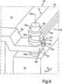
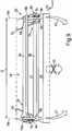
1 eine Draufsicht einer beispielhaften Ausführungsform einer Schwenkeinheit;2 eine Schnittansicht der Schwenkeinheit von1 ;3 eine Seitenansicht der Schwenkeinheit von1 ;4 eine weitere Schnittansicht eines Teilbereichs der Schwenkeinheit von1 ;5 eine Schrägansicht des Halteelements der Schwenkeinheit von1 ;6 eine Schrägansicht des Schwenkarmelements der in1 gezeigten Schwenkeinheit;7 die Schwenkeinheit aus1 aus der gleichen Perspektive wie in1 in einem verschwenkten Zustand;8 eine Schrägansicht eines Details einer beispielhaften Ausführungsform eines Möbels, anhand welchem das Zusammenspiel von einem ersten Achselement mit einem ersten Halteelement, einem erstem Schwenkarmelement und einem zweitem Schwenkarmelement erläutert wird;9 eine Schrägansicht eines weiteren beispielhaften Möbels mit einer Schwenkvorrichtung, welche eine erste Schwenkeinheit und eine zweite Schwenkeinheit aufweist.
1 a plan view of an exemplary embodiment of a pivoting unit;2 a sectional view of the pivoting unit of1 ;3 a side view of the pivot unit of1 ;4 a further sectional view of a portion of the pivot unit of1 ;5 an oblique view of the retaining element of the pivoting unit of1 ;6 an oblique view of the Schwenkarmelements the in1 shown pivot unit;7 the swivel unit off1 from the same perspective as in1 in a pivoted state;8th an oblique view of a detail of an exemplary embodiment of a piece of furniture, based on which the interaction of a first axle element with a first holding element, a first pivot arm member and a second pivot arm member is explained;9 an oblique view of another exemplary furniture with a pivoting device, which has a first pivot unit and a second pivot unit.
Bei den im Folgenden erläuterten Ausführungsbeispielen handelt es sich um bevorzugte Ausführungsformen der Erfindung. Bei den Ausführungsbeispielen stellen die beschriebenen Komponenten der Ausführungsformen jeweils einzelne, unabhängig voneinander zu betrachtende Merkmale der Erfindung dar, welche die Erfindung jeweils auch unabhängig voneinander weiterbilden und damit auch einzeln oder in einer anderen als der gezeigten Kombination als Bestandteil der Erfindung anzusehen sind. Des Weiteren sind die beschriebenen Ausführungsformen auch durch weitere der bereits beschriebenen Merkmale der Erfindung ergänzbar.The exemplary embodiments explained below are preferred embodiments of the invention. In the exemplary embodiments, the described components of the embodiments each represent individual features of the invention, which are to be considered independently of one another, which each further develop the invention independently of one another and thus also individually or in a different combination than the one shown as part of the invention. Furthermore, the described embodiments can also be supplemented by further features of the invention already described.
In den Figuren sind funktionsgleiche Elemente jeweils mit denselben Bezugszeichen versehen.In the figures, functionally identical elements are each provided with the same reference numerals.
In
Das Schwenkarmelement
Das Halteelement
In
In
Dies ist auch in
Dabei erfolgt das Umgreifen ausschließlich der Aussparung
Zur Verdeutlichung ist das Halteelement
In
Zur verbesserten Führung in der y-Richtung ist dabei im vorliegenden Beispiel der runde Führungsabschnitt
In
In
Das der ersten Schwenkachse
In
Soll das erste Gerätebauteil
Umgekehrt wird bei einem Verschwenken des ersten Gerätebauteils
Ein gleichzeitiges nach vorne Wegziehen des beispielsweise als Gerätetür ausgeführten ersten Gerätebauteils
ZITATE ENTHALTEN IN DER BESCHREIBUNG QUOTES INCLUDE IN THE DESCRIPTION
Diese Liste der vom Anmelder aufgeführten Dokumente wurde automatisiert erzeugt und ist ausschließlich zur besseren Information des Lesers aufgenommen. Die Liste ist nicht Bestandteil der deutschen Patent- bzw. Gebrauchsmusteranmeldung. Das DPMA übernimmt keinerlei Haftung für etwaige Fehler oder Auslassungen.This list of the documents listed by the applicant has been generated automatically and is included solely for the better information of the reader. The list is not part of the German patent or utility model application. The DPMA assumes no liability for any errors or omissions.
Zitierte PatentliteraturCited patent literature
- US 2904823 [0003]US 2904823 [0003]
- US 4811518 [0003]US 4811518 [0003]
- US 4947583 [0003]US 4947583 [0003]
- US 5530992 [0003]US 5530992 [0003]
Claims (10)
Translated fromGermanPriority Applications (2)
| Application Number | Priority Date | Filing Date | Title |
|---|---|---|---|
| DE102018000060.6ADE102018000060A1 (en) | 2018-01-05 | 2018-01-05 | Furniture with door hinged on both sides |
| PCT/EP2019/050071WO2019134926A1 (en) | 2018-01-05 | 2019-01-03 | Domestic appliance with door which is fixed on both sides |
Applications Claiming Priority (1)
| Application Number | Priority Date | Filing Date | Title |
|---|---|---|---|
| DE102018000060.6ADE102018000060A1 (en) | 2018-01-05 | 2018-01-05 | Furniture with door hinged on both sides |
Publications (1)
| Publication Number | Publication Date |
|---|---|
| DE102018000060A1true DE102018000060A1 (en) | 2019-07-11 |
Family
ID=66995169
Family Applications (1)
| Application Number | Title | Priority Date | Filing Date |
|---|---|---|---|
| DE102018000060.6AWithdrawnDE102018000060A1 (en) | 2018-01-05 | 2018-01-05 | Furniture with door hinged on both sides |
Country Status (1)
| Country | Link |
|---|---|
| DE (1) | DE102018000060A1 (en) |
Citations (4)
| Publication number | Priority date | Publication date | Assignee | Title |
|---|---|---|---|---|
| US2904823A (en) | 1955-09-21 | 1959-09-22 | Perrill Harlan Knox | Double hung door mounting, latching and opening means |
| US4811518A (en) | 1986-11-28 | 1989-03-14 | Ladisa Nicholas F | Door |
| US4947583A (en) | 1988-05-10 | 1990-08-14 | Sharp Kabushiki Kaisha | Opening/closing device of a door member |
| US5530992A (en) | 1993-08-27 | 1996-07-02 | Baermann; Eckhard | Double-sided hinges |
- 2018
- 2018-01-05DEDE102018000060.6Apatent/DE102018000060A1/ennot_activeWithdrawn
Patent Citations (4)
| Publication number | Priority date | Publication date | Assignee | Title |
|---|---|---|---|---|
| US2904823A (en) | 1955-09-21 | 1959-09-22 | Perrill Harlan Knox | Double hung door mounting, latching and opening means |
| US4811518A (en) | 1986-11-28 | 1989-03-14 | Ladisa Nicholas F | Door |
| US4947583A (en) | 1988-05-10 | 1990-08-14 | Sharp Kabushiki Kaisha | Opening/closing device of a door member |
| US5530992A (en) | 1993-08-27 | 1996-07-02 | Baermann; Eckhard | Double-sided hinges |
Similar Documents
| Publication | Publication Date | Title |
|---|---|---|
| DE10362318B4 (en) | Door hinge for a door of a household appliance and household appliance with at least one door hinge | |
| EP3622154A1 (en) | Guide system for guiding a door leaf | |
| DE102008005463A1 (en) | Retaining element for adjusting a lid of a piece of furniture | |
| EP2730734B1 (en) | Bidirectional retraction device for a middle sliding door | |
| DE102010002098A1 (en) | Hinge device, domestic appliance with a door and method for retrofitting a damper | |
| EP2353436B1 (en) | Fitting for a corner cupboard and corner cupboard | |
| EP0769600B1 (en) | Door check structurally combined with a door hinge | |
| DE102015206576A1 (en) | Household appliance with a retractable in a storage space door with specific storage unit | |
| EP1820422A1 (en) | Sliding guide for furniture parts sliding out of the body of a piece of furniture | |
| DE102013200850A1 (en) | Device for bending strand-shaped workpieces | |
| DE19944817A1 (en) | Holding device for a beverage container | |
| EP3387328B1 (en) | Domestic-appliance hinge and domestic appliance | |
| DE102018000046B3 (en) | Electric household appliance with door hinged on both sides | |
| EP3737816B1 (en) | Furniture hinge, furniture panel, and furniture body | |
| DE102018000060A1 (en) | Furniture with door hinged on both sides | |
| WO2006119856A1 (en) | Cupboard | |
| DE19738931C1 (en) | Hinge for container covers and esp for kitchen furniture | |
| DE102017121844A1 (en) | Guide fitting for a sliding door furniture and sliding door furniture | |
| DE102013012232A1 (en) | lever handle | |
| DE3217104C2 (en) | ||
| EP1163863B1 (en) | Rotary shelf mechanism for a corner cupboard | |
| DE212016000246U1 (en) | drawer wall | |
| DE202006010515U1 (en) | Concealed 180-degree hinge | |
| WO2019134926A1 (en) | Domestic appliance with door which is fixed on both sides | |
| DE20122827U1 (en) | Furniture hinge with opening mechanism, especially for furniture doors |
Legal Events
| Date | Code | Title | Description |
|---|---|---|---|
| R086 | Non-binding declaration of licensing interest | ||
| R082 | Change of representative | Representative=s name:PFENNING, MEINIG & PARTNER MBB PATENTANWAELTE, DE | |
| R119 | Application deemed withdrawn, or ip right lapsed, due to non-payment of renewal fee |