DE102017223682A1 - Control device for a charging device and method for controlling the charging device - Google Patents
Control device for a charging device and method for controlling the charging deviceDownload PDFInfo
- Publication number
- DE102017223682A1 DE102017223682A1DE102017223682.5ADE102017223682ADE102017223682A1DE 102017223682 A1DE102017223682 A1DE 102017223682A1DE 102017223682 ADE102017223682 ADE 102017223682ADE 102017223682 A1DE102017223682 A1DE 102017223682A1
- Authority
- DE
- Germany
- Prior art keywords
- signal
- charging
- battery
- control device
- communication
- Prior art date
- Legal status (The legal status is an assumption and is not a legal conclusion. Google has not performed a legal analysis and makes no representation as to the accuracy of the status listed.)
- Withdrawn
Links
Images


Classifications
- B—PERFORMING OPERATIONS; TRANSPORTING
- B60—VEHICLES IN GENERAL
- B60L—PROPULSION OF ELECTRICALLY-PROPELLED VEHICLES; SUPPLYING ELECTRIC POWER FOR AUXILIARY EQUIPMENT OF ELECTRICALLY-PROPELLED VEHICLES; ELECTRODYNAMIC BRAKE SYSTEMS FOR VEHICLES IN GENERAL; MAGNETIC SUSPENSION OR LEVITATION FOR VEHICLES; MONITORING OPERATING VARIABLES OF ELECTRICALLY-PROPELLED VEHICLES; ELECTRIC SAFETY DEVICES FOR ELECTRICALLY-PROPELLED VEHICLES
- B60L53/00—Methods of charging batteries, specially adapted for electric vehicles; Charging stations or on-board charging equipment therefor; Exchange of energy storage elements in electric vehicles
- B60L53/60—Monitoring or controlling charging stations
- B—PERFORMING OPERATIONS; TRANSPORTING
- B60—VEHICLES IN GENERAL
- B60L—PROPULSION OF ELECTRICALLY-PROPELLED VEHICLES; SUPPLYING ELECTRIC POWER FOR AUXILIARY EQUIPMENT OF ELECTRICALLY-PROPELLED VEHICLES; ELECTRODYNAMIC BRAKE SYSTEMS FOR VEHICLES IN GENERAL; MAGNETIC SUSPENSION OR LEVITATION FOR VEHICLES; MONITORING OPERATING VARIABLES OF ELECTRICALLY-PROPELLED VEHICLES; ELECTRIC SAFETY DEVICES FOR ELECTRICALLY-PROPELLED VEHICLES
- B60L53/00—Methods of charging batteries, specially adapted for electric vehicles; Charging stations or on-board charging equipment therefor; Exchange of energy storage elements in electric vehicles
- B60L53/10—Methods of charging batteries, specially adapted for electric vehicles; Charging stations or on-board charging equipment therefor; Exchange of energy storage elements in electric vehicles characterised by the energy transfer between the charging station and the vehicle
- B60L53/14—Conductive energy transfer
- B60L53/16—Connectors, e.g. plugs or sockets, specially adapted for charging electric vehicles
- B—PERFORMING OPERATIONS; TRANSPORTING
- B60—VEHICLES IN GENERAL
- B60L—PROPULSION OF ELECTRICALLY-PROPELLED VEHICLES; SUPPLYING ELECTRIC POWER FOR AUXILIARY EQUIPMENT OF ELECTRICALLY-PROPELLED VEHICLES; ELECTRODYNAMIC BRAKE SYSTEMS FOR VEHICLES IN GENERAL; MAGNETIC SUSPENSION OR LEVITATION FOR VEHICLES; MONITORING OPERATING VARIABLES OF ELECTRICALLY-PROPELLED VEHICLES; ELECTRIC SAFETY DEVICES FOR ELECTRICALLY-PROPELLED VEHICLES
- B60L53/00—Methods of charging batteries, specially adapted for electric vehicles; Charging stations or on-board charging equipment therefor; Exchange of energy storage elements in electric vehicles
- B60L53/10—Methods of charging batteries, specially adapted for electric vehicles; Charging stations or on-board charging equipment therefor; Exchange of energy storage elements in electric vehicles characterised by the energy transfer between the charging station and the vehicle
- B60L53/14—Conductive energy transfer
- B60L53/18—Cables specially adapted for charging electric vehicles
- B—PERFORMING OPERATIONS; TRANSPORTING
- B60—VEHICLES IN GENERAL
- B60L—PROPULSION OF ELECTRICALLY-PROPELLED VEHICLES; SUPPLYING ELECTRIC POWER FOR AUXILIARY EQUIPMENT OF ELECTRICALLY-PROPELLED VEHICLES; ELECTRODYNAMIC BRAKE SYSTEMS FOR VEHICLES IN GENERAL; MAGNETIC SUSPENSION OR LEVITATION FOR VEHICLES; MONITORING OPERATING VARIABLES OF ELECTRICALLY-PROPELLED VEHICLES; ELECTRIC SAFETY DEVICES FOR ELECTRICALLY-PROPELLED VEHICLES
- B60L53/00—Methods of charging batteries, specially adapted for electric vehicles; Charging stations or on-board charging equipment therefor; Exchange of energy storage elements in electric vehicles
- B60L53/30—Constructional details of charging stations
- B60L53/305—Communication interfaces
- B—PERFORMING OPERATIONS; TRANSPORTING
- B60—VEHICLES IN GENERAL
- B60L—PROPULSION OF ELECTRICALLY-PROPELLED VEHICLES; SUPPLYING ELECTRIC POWER FOR AUXILIARY EQUIPMENT OF ELECTRICALLY-PROPELLED VEHICLES; ELECTRODYNAMIC BRAKE SYSTEMS FOR VEHICLES IN GENERAL; MAGNETIC SUSPENSION OR LEVITATION FOR VEHICLES; MONITORING OPERATING VARIABLES OF ELECTRICALLY-PROPELLED VEHICLES; ELECTRIC SAFETY DEVICES FOR ELECTRICALLY-PROPELLED VEHICLES
- B60L53/00—Methods of charging batteries, specially adapted for electric vehicles; Charging stations or on-board charging equipment therefor; Exchange of energy storage elements in electric vehicles
- B60L53/30—Constructional details of charging stations
- B60L53/31—Charging columns specially adapted for electric vehicles
- H—ELECTRICITY
- H02—GENERATION; CONVERSION OR DISTRIBUTION OF ELECTRIC POWER
- H02J—CIRCUIT ARRANGEMENTS OR SYSTEMS FOR SUPPLYING OR DISTRIBUTING ELECTRIC POWER; SYSTEMS FOR STORING ELECTRIC ENERGY
- H02J7/00—Circuit arrangements for charging or depolarising batteries or for supplying loads from batteries
- H02J7/0013—Circuit arrangements for charging or depolarising batteries or for supplying loads from batteries acting upon several batteries simultaneously or sequentially
- H—ELECTRICITY
- H04—ELECTRIC COMMUNICATION TECHNIQUE
- H04B—TRANSMISSION
- H04B3/00—Line transmission systems
- H04B3/54—Systems for transmission via power distribution lines
- H04B3/548—Systems for transmission via power distribution lines the power on the line being DC
- H—ELECTRICITY
- H02—GENERATION; CONVERSION OR DISTRIBUTION OF ELECTRIC POWER
- H02J—CIRCUIT ARRANGEMENTS OR SYSTEMS FOR SUPPLYING OR DISTRIBUTING ELECTRIC POWER; SYSTEMS FOR STORING ELECTRIC ENERGY
- H02J2310/00—The network for supplying or distributing electric power characterised by its spatial reach or by the load
- H02J2310/40—The network being an on-board power network, i.e. within a vehicle
- H02J2310/48—The network being an on-board power network, i.e. within a vehicle for electric vehicles [EV] or hybrid vehicles [HEV]
- H—ELECTRICITY
- H02—GENERATION; CONVERSION OR DISTRIBUTION OF ELECTRIC POWER
- H02J—CIRCUIT ARRANGEMENTS OR SYSTEMS FOR SUPPLYING OR DISTRIBUTING ELECTRIC POWER; SYSTEMS FOR STORING ELECTRIC ENERGY
- H02J7/00—Circuit arrangements for charging or depolarising batteries or for supplying loads from batteries
- H02J7/00032—Circuit arrangements for charging or depolarising batteries or for supplying loads from batteries characterised by data exchange
- H02J7/00034—Charger exchanging data with an electronic device, i.e. telephone, whose internal battery is under charge
- H—ELECTRICITY
- H04—ELECTRIC COMMUNICATION TECHNIQUE
- H04B—TRANSMISSION
- H04B2203/00—Indexing scheme relating to line transmission systems
- H04B2203/54—Aspects of powerline communications not already covered by H04B3/54 and its subgroups
- H04B2203/5462—Systems for power line communications
- H04B2203/547—Systems for power line communications via DC power distribution
- Y—GENERAL TAGGING OF NEW TECHNOLOGICAL DEVELOPMENTS; GENERAL TAGGING OF CROSS-SECTIONAL TECHNOLOGIES SPANNING OVER SEVERAL SECTIONS OF THE IPC; TECHNICAL SUBJECTS COVERED BY FORMER USPC CROSS-REFERENCE ART COLLECTIONS [XRACs] AND DIGESTS
- Y02—TECHNOLOGIES OR APPLICATIONS FOR MITIGATION OR ADAPTATION AGAINST CLIMATE CHANGE
- Y02T—CLIMATE CHANGE MITIGATION TECHNOLOGIES RELATED TO TRANSPORTATION
- Y02T10/00—Road transport of goods or passengers
- Y02T10/60—Other road transportation technologies with climate change mitigation effect
- Y02T10/70—Energy storage systems for electromobility, e.g. batteries
- Y—GENERAL TAGGING OF NEW TECHNOLOGICAL DEVELOPMENTS; GENERAL TAGGING OF CROSS-SECTIONAL TECHNOLOGIES SPANNING OVER SEVERAL SECTIONS OF THE IPC; TECHNICAL SUBJECTS COVERED BY FORMER USPC CROSS-REFERENCE ART COLLECTIONS [XRACs] AND DIGESTS
- Y02—TECHNOLOGIES OR APPLICATIONS FOR MITIGATION OR ADAPTATION AGAINST CLIMATE CHANGE
- Y02T—CLIMATE CHANGE MITIGATION TECHNOLOGIES RELATED TO TRANSPORTATION
- Y02T10/00—Road transport of goods or passengers
- Y02T10/60—Other road transportation technologies with climate change mitigation effect
- Y02T10/7072—Electromobility specific charging systems or methods for batteries, ultracapacitors, supercapacitors or double-layer capacitors
- Y—GENERAL TAGGING OF NEW TECHNOLOGICAL DEVELOPMENTS; GENERAL TAGGING OF CROSS-SECTIONAL TECHNOLOGIES SPANNING OVER SEVERAL SECTIONS OF THE IPC; TECHNICAL SUBJECTS COVERED BY FORMER USPC CROSS-REFERENCE ART COLLECTIONS [XRACs] AND DIGESTS
- Y02—TECHNOLOGIES OR APPLICATIONS FOR MITIGATION OR ADAPTATION AGAINST CLIMATE CHANGE
- Y02T—CLIMATE CHANGE MITIGATION TECHNOLOGIES RELATED TO TRANSPORTATION
- Y02T90/00—Enabling technologies or technologies with a potential or indirect contribution to GHG emissions mitigation
- Y02T90/10—Technologies relating to charging of electric vehicles
- Y02T90/12—Electric charging stations
- Y—GENERAL TAGGING OF NEW TECHNOLOGICAL DEVELOPMENTS; GENERAL TAGGING OF CROSS-SECTIONAL TECHNOLOGIES SPANNING OVER SEVERAL SECTIONS OF THE IPC; TECHNICAL SUBJECTS COVERED BY FORMER USPC CROSS-REFERENCE ART COLLECTIONS [XRACs] AND DIGESTS
- Y02—TECHNOLOGIES OR APPLICATIONS FOR MITIGATION OR ADAPTATION AGAINST CLIMATE CHANGE
- Y02T—CLIMATE CHANGE MITIGATION TECHNOLOGIES RELATED TO TRANSPORTATION
- Y02T90/00—Enabling technologies or technologies with a potential or indirect contribution to GHG emissions mitigation
- Y02T90/10—Technologies relating to charging of electric vehicles
- Y02T90/14—Plug-in electric vehicles
- Y—GENERAL TAGGING OF NEW TECHNOLOGICAL DEVELOPMENTS; GENERAL TAGGING OF CROSS-SECTIONAL TECHNOLOGIES SPANNING OVER SEVERAL SECTIONS OF THE IPC; TECHNICAL SUBJECTS COVERED BY FORMER USPC CROSS-REFERENCE ART COLLECTIONS [XRACs] AND DIGESTS
- Y02—TECHNOLOGIES OR APPLICATIONS FOR MITIGATION OR ADAPTATION AGAINST CLIMATE CHANGE
- Y02T—CLIMATE CHANGE MITIGATION TECHNOLOGIES RELATED TO TRANSPORTATION
- Y02T90/00—Enabling technologies or technologies with a potential or indirect contribution to GHG emissions mitigation
- Y02T90/10—Technologies relating to charging of electric vehicles
- Y02T90/16—Information or communication technologies improving the operation of electric vehicles
Landscapes
- Engineering & Computer Science (AREA)
- Power Engineering (AREA)
- Transportation (AREA)
- Mechanical Engineering (AREA)
- Computer Networks & Wireless Communication (AREA)
- Signal Processing (AREA)
- Charge And Discharge Circuits For Batteries Or The Like (AREA)
- Electric Propulsion And Braking For Vehicles (AREA)
Abstract
Translated fromGerman
Description
Translated fromGermanDie vorliegende Erfindung betrifft eine Steuervorrichtung für eine Ladeeinrichtung zum Laden von Batterien für Elektrofahrzeuge sowie ein Verfahren zum Steuern einer solchen Ladeeinrichtung.The present invention relates to a control device for a charging device for charging batteries for electric vehicles, and a method for controlling such a charging device.
Zum Aufladen einer Batterie eines Elektrofahrzeugs wird das Elektrofahrzeug häufig an eine Ladeeinrichtung, die oft auch als „Ladestation“ bezeichnet wird, angeschlossen. Die Ladeeinrichtung kann dann die Batterie mit elektrischem Strom versorgen und aufladen. Es gibt Ladeeinrichtungen, die die Batterie des angeschlossenen Elektrofahrzeugs in unterschiedlichen Modi aufladen können. Diese Modi umfassen beispielsweise Wechselstromaufladungen sowie Gleichstromaufladungen mit jeweils unterschiedlichen Leistungen und/oder Phasen. Zur Auswahl der Modi kann gewünscht sein, dass die Ladeeinrichtung mit dem Elektrofahrzeug kommuniziert, z.B. über eine Steuervorrichtung. Hierzu wurden zum Beispiel die Standards IEC 61851 und ISO 15118 entwickelt. Es besteht ein Bedarf, mit einer einzigen Ladestation gleichzeitig mehrere Batterien für Elektrofahrzeuge aufzuladen.To charge a battery of an electric vehicle, the electric vehicle is often connected to a charging device, which is often referred to as a "charging station". The charger can then provide the battery with electrical power and charge. There are charging devices that can charge the battery of the connected electric vehicle in different modes. These modes include, for example, AC charging and DC charging, each with different powers and / or phases. To select the modes, it may be desired that the charging device communicate with the electric vehicle, e.g. via a control device. For example, the standards IEC 61851 and ISO 15118 have been developed. There is a need to simultaneously charge multiple batteries for electric vehicles with a single charging station.
Vor diesem Hintergrund besteht eine Aufgabe der vorliegenden Erfindung darin, eine verbesserte Steuervorrichtung für eine Ladeeinrichtung zum Laden von Batterien für Elektrofahrzeuge zu schaffen. Eine weitere Aufgabe besteht darin, ein verbessertes Verfahren zum Steuern einer Ladeeinrichtung zum Laden von Batterien für Elektrofahrzeuge zu schaffen.Against this background, an object of the present invention is to provide an improved control device for a charging device for charging batteries for electric vehicles. Another object is to provide an improved method of controlling a charging device for charging batteries for electric vehicles.
Gemäß einem ersten Aspekt wird eine Steuervorrichtung für eine Ladeeinrichtung zum Laden von Batterien für Elektrofahrzeuge vorgeschlagen. Die Steuervorrichtung umfasst:
- eine Signalerzeugungseinrichtung zum Erzeugen eines ersten Signals mit einer ersten Frequenz und eines zweiten Signals mit einer zweiten Frequenz, welche höher als die erste Frequenz ist;
- eine erste Kommunikationsleitung zum Übertragen des ersten Signals von der Signalerzeugungseinrichtung an mehrere Ladepunkte;
- eine zweite Kommunikationsleitung zum Übertragen des zweiten Signals von der Signalerzeugungseinrichtung an die mehreren Ladepunkte; und
- mehrere Ladepunkte, wobei jeder Ladepunkt eingerichtet ist, zum Erzeugen eines Kommunikationssignals das zweite Signal mit dem ersten Signal kapazitiv zu koppeln, wobei jeder Ladepunkt einen Anschluss zum Anschließen einer Batterie für ein Elektrofahrzeug und zum Übertragen des Kommunikationssignals an die an dem Anschluss angeschlossene Batterie umfasst, und wobei jeder Ladepunkt einen vorbestimmten Widerstand mit einem vorbestimmten Wert zum Anpassen einer Spannung des ersten Signals aufweist.
- signal generating means for generating a first signal having a first frequency and a second signal having a second frequency higher than the first frequency;
- a first communication line for transmitting the first signal from the signal generating means to a plurality of charging points;
- a second communication line for transmitting the second signal from the signal generating means to the plurality of charging points; and
- a plurality of charging points, each charging point configured to capacitively couple the second signal to the first signal to generate a communication signal, each charging point including a terminal for connecting a battery for an electric vehicle and for transmitting the communication signal to the battery connected to the terminal, and wherein each charging point has a predetermined resistance of a predetermined value for adjusting a voltage of the first signal.
Das Elektrofahrzeug, im Folgenden auch „Fahrzeug“, ist insbesondere ein Verkehrsmittel, das mit elektrischer Energie angetrieben werden kann. Das Elektrofahrzeug kann dabei zum Beispiel ein Kraftfahrzeug, insbesondere ein Elektroauto oder ein Elektromotorrad, ein Schienenfahrzeug, ein Wasserfahrzeug und/oder ein Luftfahrzeug sein. Das Elektrofahrzeug kann einen Elektromotor aufweisen, der eine zum Antrieb des Elektrofahrzeugs notwendige Energie aus der Batterie des Elektrofahrzeugs zieht, um dieses anzutreiben.The electric vehicle, hereinafter also "vehicle", is in particular a means of transport which can be powered by electrical energy. The electric vehicle may be, for example, a motor vehicle, in particular an electric car or an electric motorcycle, a rail vehicle, a watercraft and / or an aircraft. The electric vehicle may include an electric motor that draws a power necessary to drive the electric vehicle from the battery of the electric vehicle to drive it.
Die Batterie für Elektrofahrzeuge, im Folgenden auch nur „Batterie“, ist insbesondere eine Traktionsbatterie. Unter einer Batterie für Elektrofahrzeuge kann ein Energiespeicher verstanden werden, der zum Antrieb von Elektrofahrzeugen dient. Die Batterie kann mehrere zusammengeschaltete Batteriezellen aufweisen. Die Batterie kann ferner ein Batterielademodul bzw. eine Batteriesteuerung aufweisen, mit welcher die Ladeeinrichtung kommuniziert und/oder einen Ladevorgang steuert. Anhand des Batterielademoduls kann die Batterie eigenständig, also ohne dass sie mit dem Elektrofahrzeug gekoppelt ist, aufgeladen werden.The battery for electric vehicles, hereinafter also referred to as "battery", is in particular a traction battery. Under a battery for electric vehicles, an energy storage can be understood, which is used to drive electric vehicles. The battery may have a plurality of interconnected battery cells. The battery may further comprise a battery charging module or battery controller, with which the charging device communicates and / or controls a charging process. With the help of the battery charging module, the battery can be charged independently, ie without being coupled to the electric vehicle.
Die Ladeeinrichtung, auch „Ladestation“, ist insbesondere geeignet, mehrere Batterien gleichzeitig aufzuladen. Hierzu kann die Ladeeinrichtung die Batterien mit elektrischem Strom versorgen. Zum Aufladen einer Batterie kann diese aus dem Fahrzeug herausgenommen werden oder innerhalb des Fahrzeugs gelassen werden. Die Batterie kann in dem Fahrzeug fest eingebettet sein, weshalb auch von Aufladen von Fahrzeugen gesprochen wird. Insbesondere ist die Ladeeinrichtung geeignet, mehrere Fahrzeuge gleichzeitig aufzuladen.The charging device, also called "charging station", is particularly suitable for charging several batteries at the same time. For this purpose, the charging device can supply the batteries with electric current. To charge a battery, it can be removed from the vehicle or left inside the vehicle. The battery can be firmly embedded in the vehicle, which is why talking about charging vehicles. In particular, the charging device is suitable to charge several vehicles at the same time.
Die Ladeeinrichtung weist insbesondere mehrere Ladepunkte auf. An jeden Ladepunkt kann z.B. eine Batterie und/oder ein Fahrzeug angeschlossen und aufgeladen werden. Die maximale Anzahl an Batterien, die zeitgleich angeschlossen/aufgeladen werden können, kann der Anzahl an Ladepunkten der Ladeeinrichtung entsprechen. Es ist auch möglich, dass an der Ladeeinrichtung zu einem vorbestimmten Zeitpunkt z.B. keine oder nur eine einzige Batterie angeschlossen/aufgeladen wird.The charging device has in particular several charging points. At each charging point, e.g. a battery and / or a vehicle are connected and charged. The maximum number of batteries that can be connected / charged at the same time can correspond to the number of charging points of the charging device. It is also possible that at the charging device at a predetermined time, e.g. no or only a single battery is connected / charged.
Die Steuervorrichtung ist insbesondere Teil der Ladeeinrichtung. Sie kann dazu dienen, eine Kommunikation zwischen der Ladeeinrichtung und einer angeschlossenen Batterie bzw. einem angeschlossenem Elektrofahrzeug herzustellen. Unter der Kommunikation zwischen der Ladeeinrichtung und der Batterie/dem Elektrofahrzeug ist insbesondere das Übertragen von Ladedaten zwischen der Ladeeinrichtung und der Batteriesteuerung zu verstehen. Das Übertragen der Ladedaten kann mit Hilfe des ersten Signals, des zweiten Signals und des Kommunikationssignals erfolgen. Diese Kommunikation kann dazu dienen, der Batterie oder der Batteriesteuerung oder dem Elektrofahrzeug eine Ladeinformation von der Ladeeinrichtung bereitzustellen. Es kann im Rahmen der Kommunikation auch eine Ladeinformation von dem Elektrofahrzeug/der Batteriesteuerung an die Ladeeinrichtung übertragen werden. Diese Ladeinformation umfasst beispielsweise eine Angabe über die Bereitschaft des Fahrzeugs, Energie bzw. elektrischen Strom aufzunehmen. Sie kann auch dazu dienen, Ladeparameter (z.B. eine maximale Spannung des lieferbaren elektrischen Stroms oder einen Ladezustand der Batterie) zu bestimmen und/oder zu ändern sowie eine Authentifizierung des Fahrzeugs und/oder eine Zertifikatsüberprüfung durchzuführen.The control device is in particular part of the charging device. It can serve to establish communication between the charging device and a connected battery or a connected electric vehicle. Under the Communication between the charging device and the battery / the electric vehicle is to be understood in particular as the transfer of charging data between the charging device and the battery control. The transfer of the charge data can be carried out with the aid of the first signal, the second signal and the communication signal. This communication may serve to provide the battery or the battery controller or the electric vehicle with charging information from the charging device. It is also possible in the context of communication to transfer charging information from the electric vehicle / battery control to the charging device. This charging information includes, for example, an indication of the readiness of the vehicle to absorb energy or electric current. It may also serve to determine and / or change charging parameters (eg a maximum voltage of the deliverable electrical current or a state of charge of the battery) as well as to perform an authentication of the vehicle and / or a certificate check.
Die Ladeinformation kann der Batterie/dem Elektrofahrzeug mit Hilfe des Kommunikationssignals über den Anschluss des Ladepunkts übermittelt werden. Der Anschluss des Ladepunkts dient insbesondere nur zur Übertragung des Kommunikationssignals. Zum Aufladen der Batterie kann z.B. ein separater Ladeanschluss oder Ladepin an dem Ladepunkt vorgesehen sein, durch welchen elektrischer Strom an die Batterie übertragen werden kann.The charging information may be communicated to the battery / electric vehicle via the communication signal via the charging point connection. The connection of the charging point is used in particular only for the transmission of the communication signal. For charging the battery, e.g. a separate charging port or charging pin may be provided at the charging point, through which electrical power can be transmitted to the battery.
Unter dem Erzeugen des Kommunikationssignals wird insbesondere ein Aufmodulieren des zweiten Signals auf das erste Signal verstanden. Das Kommunikationssignal ist insbesondere eine Überlagerung des ersten und des zweiten Signals. Das erste Signal ist insbesondere ein Wechselspannungssignal. Zum Erzeugen des Kommunikationssignals kann das zweite Signal in jedem der Ladepunkte kapazitiv mit dem ersten Signal gekoppelt werden. Hierzu kann jeder Ladepunkt einen Kondensator aufweisen, der die erste Kommunikationsleitung und die zweite Kommunikationsleitung miteinander verbindet. Der Kondensator ist insbesondere ein Kopplungskondensator, der für Hochfrequenzsignale, z.B. für das zweite Signal, durchlässig ist aber für Niederfrequenzsignal, zum Beispiel für das erste Signal, undurchlässig ist. Der Kondensator kann derart gewählt werden, dass er das zweite Signal durchlässt, aber das erste Signal nicht.The generation of the communication signal is understood in particular to be a modulation of the second signal onto the first signal. The communication signal is in particular a superposition of the first and the second signal. The first signal is in particular an AC signal. To generate the communication signal, the second signal in each of the charging points can be capacitively coupled to the first signal. For this purpose, each charging point may have a capacitor which connects the first communication line and the second communication line with each other. The capacitor is in particular a coupling capacitor suitable for high frequency signals, e.g. for the second signal, but is permeable to low frequency signal, for example for the first signal, is impermeable. The capacitor may be chosen to pass the second signal but not the first signal.
Die erste und die zweite Kommunikationsleitung können Kabel sein, die jeweils das erste und das zweite Signal von der Signalerzeugungseinrichtung, die diese Signale erzeugt, an die jeweiligen Ladepunkte übertragen.The first and second communication lines may be cables which respectively transmit the first and second signals from the signal generating means which generates these signals to the respective charging points.
Jeder Ladepunkt weist eine vorbestimmte Impedanz auf, die durch den vorbestimmten Widerstand erzeugt wird. Dieser vorbestimmte Widerstand ist insbesondere seriell entlang der ersten Kommunikationsleitung geschaltet, um die Spannung des ersten Signals anzupassen.Each charging point has a predetermined impedance generated by the predetermined resistance. In particular, this predetermined resistor is connected in series along the first communication line to adjust the voltage of the first signal.
In Ausführungsformen ist der vorbestimmte Widerstand eingerichtet, die Spannung des ersten Signals bei Anschließen einer Batterie/eines Fahrzeugs an den Anschluss zu Reduzieren. Unter dem Anpassen der Spannung des ersten Signals wird insbesondere ein Reduzieren der Spannung des ersten Signals bei Anschließen einer Batterie/eines Fahrzeugs an den Anschluss gemeint. Der vorbestimmte Widerstand ist insbesondere zum Anpassen der Impedanz einer Spannungsquelle des ersten Signals geeignet.In embodiments, the predetermined resistance is configured to reduce the voltage of the first signal when connecting a battery / vehicle to the port. By adjusting the voltage of the first signal is meant, in particular, reducing the voltage of the first signal when connecting a battery / vehicle to the terminal. The predetermined resistance is particularly suitable for adjusting the impedance of a voltage source of the first signal.
Der vorbestimmte Wert des vorbestimmten Widerstands ist insbesondere durch einen Standard für die Kommunikation zwischen der Ladeeinrichtung und der Batterie/des Elektrofahrzeugs vorgegeben. Dieser Standard kann der Standard IEC 61851, insbesondere die Version IEC 61851-1, 3. Auflage, Februar 2017, sein. Dieser Standard schreibt insbesondere vor, dass die Spannung des ersten Signals durch einen Widerstand mit einem vorgegebenen Wert belastet werden muss. In der beschriebenen Steuervorrichtung wird dieser standardgemäße Widerstand insbesondere in jedem einzelnen Ladepunkt vorgesehen, indem in jedem Ladepunkt ein vorbestimmter Widerstand angeordnet wird. Der vorbestimmte Widerstand kann dabei dem standardkonformen Widerstand entsprechen. Dadurch wird insbesondere erreicht, dass mehrere Fahrzeuge an einer einzigen standardkonformen Ladeeinrichtung aufgeladen werden können. Der vorbestimmte Widerstand kann z.B. ein 1kΩ-Widerstand sein.Specifically, the predetermined value of the predetermined resistance is predetermined by a standard for the communication between the charging device and the battery / the electric vehicle. This standard may be the standard IEC 61851, in particular the version IEC 61851-1, 3rd edition, February 2017. This standard stipulates in particular that the voltage of the first signal must be loaded by a resistor with a predetermined value. In the described control device, this standard resistance is provided in particular in each individual charging point by arranging a predetermined resistance in each charging point. The predetermined resistance can correspond to the standard-compliant resistance. This achieves in particular that several vehicles can be charged to a single standard compliant charging device. The predetermined resistance may be e.g. be a 1kΩ resistor.
In der beschriebenen Steuervorrichtung sind insbesondere mehrere Ladepunkte an einer einzigen Signalerzeugungseinrichtung vorgesehen. Dadurch kann erreicht werden, dass sowohl das erste als auch das zweite Signal nur einmalig erzeugt werden muss. Das erste und das zweite Signal können durch mehrere Ladepunkte als ein Kommunikationssignal an mehrere Batterien/Elektrofahrzeuge übertragen werden. Die Ladeeinrichtung kann dadurch insbesondere mit mehreren Batterien/Elektrofahrzeugen gleichzeitig kommunizieren.In the described control device, in particular a plurality of charging points are provided on a single signal generating device. It can thereby be achieved that both the first and the second signal only have to be generated once. The first and second signals may be transmitted through multiple charging points as a communication signal to a plurality of batteries / electric vehicles. The charging device can thereby communicate in particular with several batteries / electric vehicles at the same time.
Somit kann die Steuervorrichtung die Kommunikation bzw. den Datenaustausch mit mehreren Batterien/Elektrofahrzeugen gleichzeitig unterstützen, ohne für jeden Ladepunkt eine eigene Signalerzeugungseinrichtung vorzusehen. Dieses ist vorteilhaft, weil die Signalerzeugungseinrichtung häufig ein komplexes Bauteil ist, das einen Mikrocontroller umfasst. Dadurch, dass die Steuervorrichtung eine einzige Signalerzeugungseinrichtung umfasst kann die Steuervorrichtung einfacher und kostengünstiger hergestellt werden.Thus, the control device can simultaneously support the communication or the data exchange with a plurality of batteries / electric vehicles without providing a separate signal generating device for each charging point. This is advantageous because the signal generation device is often a complex component that includes a microcontroller. Because of that Control device comprises a single signal generating device, the control device can be made easier and cheaper.
Mikrocontroller sind nicht nur aufwendig herzustellen, sondern auch nicht so hitzebeständig wie Widerstände, Kondensatoren und elektrische Leitungen. Tatsächlich sind Mikrocontroller wegen des PN-Übergangs im Silizium nur bis circa 105°C beständig. Aufgrund des elektrischen Stroms kann es in den Ladepunkten jedoch zu höheren Temperaturen kommen, weshalb es nicht erwünscht ist, den Mikrocontroller in den Ladepunkten vorzusehen. Die Bauteile, die in der beschriebenen Steuervorrichtung Teil des Ladepunkts sind, insbesondere der Kondensator zum kapazitiven Koppeln des zweiten Signals mit dem ersten Signal, der vorbestimmte Widerstand und die elektrischen Leitungen zum Leiten der Signale, sind auch bis Temperaturen von 200°C beständig. Indem der Mikrocontroller entfernt von den Ladepunkten vorgesehen wird, kann verhindert werden, dass dieser bei zu hohen Temperaturen geschädigt wird.Microcontrollers are not only expensive to produce, but also less resistant to heat than resistors, capacitors and electrical cables. In fact, because of the PN junction in silicon, microcontrollers are only stable up to about 105 ° C. However, due to the electric current, higher temperatures may occur in the charging points, and it is therefore undesirable to provide the microcontroller in the charging points. The components which are part of the charging point in the described control device, in particular the capacitor for capacitively coupling the second signal to the first signal, the predetermined resistance and the electrical lines for conducting the signals, are also resistant to temperatures of 200 ° C. By providing the microcontroller away from the charging points, it can be prevented from being damaged at too high temperatures.
Der vorbestimmte Widerstand ist insbesondere derart nahe am Fahrzeug angeordnet, dass eine Unterdrückung von unerwünschten Störungen in der Signalübertragung erfolgen kann. Wäre der vorbestimmte Widerstand im Bereich der Signalerzeugungseinrichtung vorgesehen, würden wegen der Länge der ersten und zweiten Kommunikationsleitungen häufig Störungen in den übertragenen Signalen auftreten. Die Störungen können z.B. durch eine Stromversorgungsleitung eingekoppelt werden. Da ein Abstand zwischen dem Ladepunkt und der Batterie kleiner als ein Abstand zwischen der Signalerzeugungseinrichtung und der Batterie ist, ist es vorteilhaft, den vorbestimmten Widerstand in den jeweiligen Ladepunkten vorzusehen. Dadurch können Störungen reduziert werden.The predetermined resistance is arranged in particular so close to the vehicle that a suppression of unwanted disturbances in the signal transmission can take place. If the predetermined resistance were provided in the region of the signal generating device, because of the length of the first and second communication lines, interference would frequently occur in the transmitted signals. The disturbances can e.g. be coupled by a power supply line. Since a distance between the charging point and the battery is smaller than a distance between the signal generating device and the battery, it is advantageous to provide the predetermined resistance in the respective charging points. This can reduce interference.
Anders ausgedrückt, kann die Strecke mit einer hohen Impedanz, also die Strecke zwischen dem vorbestimmten Widerstand und dem Fahrzeug, kurz gehalten werden, weil der vorbestimmte Widerstand in den jeweiligen Ladepunkten vorgesehen ist. Dadurch können die Störungen klein gehalten werden. Die Strecke mit einer niedrigen Impedanz, also die Strecke zwischen der Signalerzeugungseinrichtung und den jeweiligen vorbestimmten Widerständen, kann dabei groß bleiben.In other words, because the predetermined resistance is provided in the respective charging points, the high impedance route, that is, the distance between the predetermined resistance and the vehicle, can be kept short. As a result, the disturbances can be kept small. The route with a low impedance, ie the distance between the signal generating device and the respective predetermined resistances, can remain large.
Gemäß einer Ausführungsform umfasst jeder Ladepunkt ein Belastungselement, welches dazu eingerichtet ist, das zweite Signal derart zu belasten, dass ein Pegel des zweiten Signals unabhängig davon, ob die Batterie an dem Ladepunkt angeschlossen ist oder nicht, konstant bleibt.According to one embodiment, each charging point comprises a loading element which is adapted to load the second signal such that a level of the second signal remains constant regardless of whether the battery is connected to the charging point or not.
Der Pegel des zweiten Signals bei angeschlossener Batterie ist somit insbesondere derselbe, wie wenn keine Batterie angeschlossen ist. Anders ausgedrückt, bleibt ein Pegel des zweiten Signals konstant. Dieses führt dazu, dass Vorgänge an einem Ladepunkt, z.B. das Koppeln/Entkoppeln einer Batterie, keine Rückwirkungen auf die anderen Ladepunkte und/oder keine Rückwirkungen auf die Signalerzeugungseinrichtung haben. Das zweite Signal bleibt insbesondere dasselbe, unabhängig davon, wie viele Batterien an der Ladeeinrichtung gekoppelt sind.The level of the second signal when the battery is connected is thus in particular the same as when no battery is connected. In other words, a level of the second signal remains constant. This results in events at a charging point, e.g. the coupling / decoupling of a battery, have no repercussions on the other charging points and / or no repercussions on the signal generating device. In particular, the second signal remains the same regardless of how many batteries are coupled to the charger.
Das Belastungselement kann das zweite Signal genauso stark belasten, wie ein üblicher interner Widerstand der Batterie/des Elektrofahrzeugs. Bei dem internen Widerstand handelt es sich insbesondere um einen Widerstand der Batterie/der Fahrzeugs, der auf einer Kommunikationsseite der Batterie/des Fahrzeugs und nicht auf einer Leistungsseite der Batterie/der Fahrzeugs liegt. Das Belastungselement kann beispielsweise ein Dämpfungselement, insbesondere ein Widerstand sein. Es kann sich dabei um einen veränderlichen Widerstand handeln, welcher insbesondere an die Leitung des zweiten Signals zuschaltbar ist.The loading element may load the second signal as much as a common internal resistance of the battery / electric vehicle. In particular, the internal resistance is a resistance of the battery / vehicle that is located on a communication side of the battery / vehicle and not on a power side of the battery / vehicle. The loading element may for example be a damping element, in particular a resistor. It may be a variable resistor, which can be connected in particular to the line of the second signal.
In Ausführungsformen weist jeder Ladepunkt einen zuschaltbaren Widerstand auf, der zwischen der zweiten Kommunikationsleitung und Masse schaltbar ist. Der zuschaltbare Widerstand ist dabei insbesondere ein Belastungselement. Der zuschaltbare Widerstand beträgt insbesondere denselben Wert, wie der übliche interne Widerstand der Batterie/des Elektrofahrzeugs. Der Wert des zuschaltbaren Widerstands kann z.B. 50Ω betragen. Der zuschaltbare Widerstand wird insbesondere in einem Zustand, in dem keine Batterie/kein Fahrzeug an dem Ladepunkt angeschlossen ist, zwischen der zweiten Kommunikationsleitung und Masse zugeschaltet. Der zuschaltbare Widerstand belastet dabei das zweite Signal insbesondere genauso stark wie es der interne Widerstand einer angeschlossenen Batterie/eines angeschlossenen Fahrzeugs belasten würde.In embodiments, each charging point has a switchable resistor that is switchable between the second communication line and ground. The switchable resistor is in particular a load element. The switchable resistor is in particular the same value as the usual internal resistance of the battery / the electric vehicle. The value of the switchable resistor can be e.g. 50Ω. The switchable resistor is connected between the second communication line and ground, in particular in a state in which no battery / vehicle is connected to the charging point. The switchable resistor loads the second signal in particular just as much as it would burden the internal resistance of a connected battery / a connected vehicle.
Es ist auch denkbar, das zweite Signal aus dem Kommunikationssignal auszukoppeln und das ausgekoppelte Signal zu belasten, insbesondere mit einem zuschaltbaren Widerstand zu belasten.It is also conceivable to decouple the second signal from the communication signal and to load the decoupled signal, in particular to load a switchable resistor.
Gemäß einer weiteren Ausführungsform sind die Signalerzeugungseinrichtung und die mehreren Ladepunkte physikalisch, insbesondere räumlich, voneinander getrennte Einrichtungen. Das heißt z.B., dass die Signalerzeugungseinrichtung von den mehreren Ladepunkten trennbar ist. Insbesondere sind die Ladepunkte distanziert von der Signalerzeugungseinrichtung angeordnet.According to a further embodiment, the signal generating device and the plurality of charging points are physically, in particular spatially, separate devices. That is, for example, that the signal generating means is separable from the plurality of charging points. In particular, the charging points are arranged at a distance from the signal generating device.
Gemäß einer weiteren Ausführungsform ist das erste Signal ein pulsweitenmoduliertes Signal (PWM-Signal) und/oder das zweite Signal ist ein Power Line Communication Signal (PLC-Signal).According to a further embodiment, the first signal is a pulse width modulated signal (PWM signal) and / or the second signal is a power line communication signal (PLC signal).
Das erste Signal, das zweite Signal und das Kommunikationssignal können zum Übertragen von Daten verwendet werden. Das PWM-Signal ist insbesondere ein Wechselspannungssignal mit einer ±12V-Spannung und einer 1.000Hz-Frequenz. Das PWM-Signal kann ein Rechtecksignal sein. Das Tastverhältnis des PWM-Signals kann dabei die in dem Standard IEC 61851 bestimmte Bedeutung annehmen.The first signal, the second signal, and the communication signal may be used to transmit data. In particular, the PWM signal is an AC signal with a ± 12V voltage and a 1,000 Hz frequency. The PWM signal may be a square wave signal. The duty cycle of the PWM signal can assume the meaning defined in the IEC 61851 standard.
Das zweite Signal kann ein Hochfrequenzkommunikationssignal, z.B. ein PLC-Signal sein. Das PLC-Signal hat beispielsweise eine ±3V Spannung, und eine zweite Frequenz, die bedeutend höher als die erste Frequenz des ersten Signals ist. Die zweite Frequenz beträgt z.B. 2 bis 20MHz. Das PLC-Signal kann an eine bestimmte Batterie oder an ein bestimmtes Elektrofahrzeug, das an einem bestimmten Ladepunkt angeschlossen ist, adressiert sein. Das PLC-Signal wird beispielsweise gemäß einem Internet-Protokoll übertragen. Das PLC-Signal kann in einem Headerabschnitt angeben, für welchen Ladepunkt es bestimmt ist. Das Elektrofahrzeug oder das Batterielademodul kann anhand des Headerabschnitts bestimmen, ob das auf den Headerabschnitt folgende Signal für das Elektrofahrzeug oder das Batterielademodul bestimmt ist und dieses ggf. auslesen/berücksichtigen. Falls erkannt wird, dass das auf den Headerabschnitt folgende Signal für einen anderen Empfänger bestimmt ist, wird es beispielsweise ignoriert. Insbesondere kann das auf den Headerabschnitt folgende Signal verschlüsselt vorliegen.The second signal may be a high frequency communication signal, e.g. be a PLC signal. For example, the PLC signal has a ± 3V voltage, and a second frequency that is significantly higher than the first frequency of the first signal. The second frequency is e.g. 2 to 20MHz. The PLC signal may be addressed to a particular battery or to a particular electric vehicle connected at a particular charging point. The PLC signal is transmitted, for example, according to an internet protocol. The PLC signal may indicate in a header section for which charging point it is intended. Based on the header section, the electric vehicle or the battery charging module can determine whether the signal following the header section is intended for the electric vehicle or the battery charging module and, if necessary, read out / take this into account. For example, if it is detected that the signal following the header portion is destined for another receiver, it is ignored. In particular, the signal following the header section can be encrypted.
Das Kommunikationssignal, dass durch das Aufmodulieren des PLC-Signals auf das PWM-Signal erzeugt wird, ist im Wesentlichen ein ±12V Rechtecksignal mit einer ersten Frequenz, auf welches ein ±3V-Signal mit einer zweiten Frequenz, die höher als die erste Frequenz ist, aufaddiert ist.The communication signal generated by modulating the PLC signal onto the PWM signal is essentially a ± 12V square wave signal having a first frequency to which a ± 3V signal having a second frequency higher than the first frequency , is added up.
Gemäß einer weiteren Ausführungsform ist jeder Ladepunkt eingerichtet, das Kommunikationssignal gemäß dem Standard IEC 61851 (insbesondere IEC 61851-1, 3. Auflage, Februar 2017),
Gemäß einer weiteren Ausführungsform beträgt der vorbestimmte Wert des vorbestimmten Widerstands zwischen 0,8 und 1,2kΩ. In Ausführungsformen beträgt der Wert der Gesamtimpedanz genau 1kΩ und entspricht somit dem Standard IEC 61851.According to another embodiment, the predetermined value of the predetermined resistance is between 0.8 and 1.2kΩ. In embodiments, the value of the total impedance is exactly 1kΩ and thus complies with the IEC 61851 standard.
Gemäß einer weiteren Ausführungsform belastet das Belastungselement das zweite Signal mit einem Belastungswiderstand mit einem Wert zwischen 30 und 70 Ω, insbesondere zwischen 40 und 60 Ω. Bei dem Belastungswiderstand kann es sich um den zuschaltbaren Widerstand handeln.According to a further embodiment, the loading element loads the second signal with a load resistor having a value between 30 and 70 Ω, in particular between 40 and 60 Ω. The load resistance may be the switchable resistor.
Gemäß einer weiteren Ausführungsform ist jeder Ladepunkt eingerichtet, in einem Zustand, in dem keine Batterie an dem Ladepunkt angeschlossen ist, das Belastungselement zwischen der zweiten Kommunikationsleitung und Masse zuzuschalten.According to another embodiment, each charging point is arranged to switch on the loading element between the second communication line and ground in a state in which no battery is connected to the charging point.
Gemäß einer weiteren Ausführungsform ist jeder Ladepunkt als Teil eines Ladekabels und/oder eines Steckers zum Laden von Batterien für Elektrofahrzeuge ausgebildet. Jeder Ladepunkt kann in einem Ladekabel oder in einem Stecker, z.B. in einem Stecker des Typs
Gemäß einer weiteren Ausführungsform ist der Anschluss ein Control-Pilot-Kontakt/Pin einer Steckdose für das Laden von Batterien für Elektrofahrzeuge, insbesondere einer Typ-
Gemäß einer weiteren Ausführungsform weist jeder Ladepunkt ferner zumindest einen Stromversorgungsanschluss zum Versorgen der angeschlossenen Batterie mit elektrischem Strom auf. Die Stromversorgungsleitung zum Versorgen der Batterie mit elektrischem Strom verläuft insbesondere parallel zu den ersten und zweiten Kommunikationsleitungen und kann in einem selben Ladekabel wie diese vorgesehen sein.According to a further embodiment, each charging point further comprises at least one power supply connection for supplying the connected battery with electric current. The power supply line for supplying the battery with electric current runs in particular parallel to the first and second communication lines and may be provided in a same charging cable as this.
Gemäß einer weiteren Ausführungsform umfasst zumindest ein Ladepunkt eine Detektionseinrichtung mit einer Spannungsmesseinrichtung, die dazu eingerichtet ist, unter Berücksichtigung einer gemessenen Spannung des Kommunikationssignals zu bestimmen, ob eine Batterie für Elektrofahrzeuge an dem Anschluss angeschlossen ist oder nicht.According to a further embodiment, at least one charging point comprises a detection device with a voltage measuring device, which is set up to determine whether a battery for electric vehicles is connected to the connection or not, taking into account a measured voltage of the communication signal.
Die Spannungsmesseinrichtung kann insbesondere eine Spannung des Kommunikationssignals, das der Batterie über den Anschluss bereitgestellt wird, messen. Die Spannungsmesseinrichtung kann beispielsweise als ein Fenster-Discriminator ausgebildet sein. Die Spannungsmesseinrichtung kann z.B. das Zuschalten des zuschaltbaren Widerstands steuern.In particular, the voltage measuring device may measure a voltage of the communication signal provided to the battery via the terminal. The voltage measuring device can be designed, for example, as a window discriminator. The tension measuring device can eg control the connection of the switchable resistor.
Gemäß einer weiteren Ausführungsform ist das erste Signal ein PWM-Signal mit einer Spannung zwischen ±11V und ±13V, insbesondere mit einer Spannung von ±12V, und einer Frequenz zwischen 900 und 1100Hz, insbesondere von 1000Hz.According to a further embodiment, the first signal is a PWM signal with a voltage between ± 11V and ± 13V, in particular with a voltage of ± 12V, and a frequency between 900 and 1100Hz, in particular of 1000Hz.
Gemäß einem zweiten Aspekt wird ein Verfahren zum Steuern einer Ladeeinrichtung zum Laden von Batterien für Elektrofahrzeuge mit einer Steuereinrichtung gemäß dem ersten Aspekt oder gemäß einer Ausführungsform des ersten Aspekts vorgeschlagen.According to a second aspect, a method for controlling a charging device for charging batteries for electric vehicles with a control device according to the first aspect or according to an embodiment of the first aspect is proposed.
Die für die vorgeschlagene Steuervorrichtung beschriebenen Ausführungsformen und Merkmale gelten für das vorgeschlagene Verfahren entsprechend.The embodiments and features described for the proposed control device apply correspondingly to the proposed method.
Das Verfahren umfasst insbesondere die Schritte:
- Erzeugen eines ersten Signals mit einer ersten Frequenz und eines zweiten Signals mit einer zweiten Frequenz, welche höher als die erste Frequenz ist (mit einer Signalerzeugungseinrichtung);
- Übertragen des ersten Signals (von der Signalerzeugungseinrichtung) an mehrere Ladepunkte über eine erste Kommunikationsleitung;
- Übertragen des zweiten Signals (von der Signalerzeugungseinrichtung) an die mehreren Ladepunkte über eine zweite Kommunikationsleitung;
- kapazitives Koppeln des zweiten Signals mit dem ersten Signal zum Erzeugen eines Kommunikationssignals in den jeweiligen Ladepunkten, wobei jeder Ladepunkt einen Anschluss zum Anschließen einer Batterie für ein Elektrofahrzeug und zum Übertragen des Kommunikationssignals an die an dem Anschluss angeschlossene Batterie umfasst, und wobei jeder Ladepunkt einen vorbestimmten Widerstand mit einem vorbestimmten Wert zum Anpassen einer Spannung des ersten Signals aufweist.
- Generating a first signal having a first frequency and a second signal having a second frequency which is higher than the first frequency (with signal generating means);
- Transmitting the first signal (from the signal generating means) to a plurality of charging points via a first communication line;
- Transmitting the second signal (from the signal generating means) to the plurality of charging points via a second communication line;
- capacitively coupling the second signal to the first signal to generate a communication signal in the respective charging points, each charging point including a terminal for connecting a battery for an electric vehicle and transmitting the communication signal to the battery connected to the terminal, and wherein each charging point has a predetermined one Resistor having a predetermined value for adjusting a voltage of the first signal.
Gemäß einem dritten Aspekt wird ein Computerprogrammprodukt vorgeschlagen, welches auf einer programmgesteuerten Einrichtung die Durchführung des Verfahrens gemäß dem zweiten Aspekt oder gemäß einer Ausführungsform des zweiten Aspekts veranlasst. Die programmgesteuerte Einrichtung ist insbesondere die Steuervorrichtung gemäß dem ersten Aspekt oder gemäß einer Ausführungsform des ersten Aspekts.According to a third aspect, a computer program product is proposed, which causes the execution of the method according to the second aspect or according to an embodiment of the second aspect on a program-controlled device. The program-controlled device is in particular the control device according to the first aspect or according to an embodiment of the first aspect.
Ein Computerprogrammprodukt, wie z.B. ein Computerprogramm-Mittel, kann beispielsweise als Speichermedium, wie z.B. Speicherkarte, USB-Stick, CD-ROM, DVD, oder auch in Form einer herunterladbaren Datei von einem Server in einem Netzwerk bereitgestellt oder geliefert werden. Dies kann zum Beispiel in einem drahtlosen Kommunikationsnetzwerk durch die Übertragung einer entsprechenden Datei mit dem Computerprogrammprodukt oder dem Computerprogramm-Mittel erfolgen.A computer program product, such as a computer program means may, for example, be used as a storage medium, e.g. Memory card, USB stick, CD-ROM, DVD, or even in the form of a downloadable file provided by a server in a network or delivered. This can be done, for example, in a wireless communication network by transmitting a corresponding file with the computer program product or the computer program means.
Gemäß einem vierten Aspekt wird eine Ladeeinrichtung zum Laden von Batterien für Elektrofahrzeuge, welche die Steuervorrichtung gemäß dem ersten Aspekt oder gemäß einer Ausführungsform des ersten Aspekts umfasst.According to a fourth aspect, a charging device for charging electric vehicle batteries, which includes the control device according to the first aspect or according to an embodiment of the first aspect.
Weitere mögliche Implementierungen der Erfindung umfassen auch nicht explizit genannte Kombinationen von zuvor oder im Folgenden bezüglich der Ausführungsbeispiele beschriebenen Merkmale oder Ausführungsformen. Dabei wird der Fachmann auch Einzelaspekte als Verbesserungen oder Ergänzungen zu der jeweiligen Grundform der Erfindung hinzufügen.Further possible implementations of the invention also include not explicitly mentioned combinations of features or embodiments described above or below with regard to the exemplary embodiments. The skilled person will also add individual aspects as improvements or additions to the respective basic form of the invention.
Weitere vorteilhafte Ausgestaltungen und Aspekte der Erfindung sind Gegenstand der Unteransprüche sowie der im Folgenden beschriebenen Ausführungsbeispiele. Im Weiteren wird die Erfindung anhand von bevorzugten Ausführungsformen unter Bezugnahme auf die beigelegten Figuren näher erläutert.
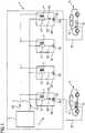
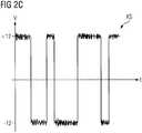
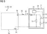
1 zeigt eine Steuervorrichtung für eine Ladeeinrichtung gemäß einer ersten Ausführungsform;2A ,2B und2C zeigen Beispiele für einen zeitlichen Ablauf eines ersten Signals, eines zweiten Signals und eines Kommunikationssignals;3 zeigt eine Steuervorrichtung für eine Ladeeinrichtung gemäß einer zweiten Ausführungsform;4 zeigt eine Steuervorrichtung für eine Ladeeinrichtung gemäß einer dritten Ausführungsform; und5 zeigt ein Beispiel für einen Schaltkreis, der ein Elektrofahrzeug und eine Steuervorrichtung gemäß der ersten, zweiten oder dritten Ausführungsform umfasst.
1 shows a control device for a charging device according to a first embodiment;2A .2 B and2C show examples of a timing of a first signal, a second signal and a communication signal;3 shows a control device for a charging device according to a second embodiment;4 shows a control device for a charging device according to a third embodiment; and5 shows an example of a circuit comprising an electric vehicle and a control device according to the first, second or third embodiment.
In den Figuren sind gleiche oder funktionsgleiche Elemente mit denselben Bezugszeichen versehen worden, sofern nichts anderes angegeben ist.In the figures, the same or functionally identical elements have been given the same reference numerals, unless stated otherwise.
Die
In der
Jeder Anschluss
Die Steuervorrichtung
Das zweite Signal
Die Steuervorrichtung
Das Kommunikationssignal KS enthält eine Ladeinformation, die von der Signalerzeugungseinrichtung
Der Kondensator
Das PWM-Signal
Dadurch, dass die jeweiligen vorbestimmten Widerstände
Die in der
Die
In der
Ferner weist jeder Ladepunkt
Falls eine Batterie
In einem zweiten Zustand, in dem keine Batterie
In der
Jeder Ladepunkt
Falls eine Batterie
Die
Der Ladepunkt
Die
In dem Fahrzeug
Der interne Widerstand
Beim Anschließen der Batterie
Obwohl die vorliegende Erfindung anhand von Ausführungsbeispielen beschrieben wurde, ist sie vielfältig modifizierbar. Die Anzahl an Ladepunkten
ZITATE ENTHALTEN IN DER BESCHREIBUNG QUOTES INCLUDE IN THE DESCRIPTION
Diese Liste der vom Anmelder aufgeführten Dokumente wurde automatisiert erzeugt und ist ausschließlich zur besseren Information des Lesers aufgenommen. Die Liste ist nicht Bestandteil der deutschen Patent- bzw. Gebrauchsmusteranmeldung. Das DPMA übernimmt keinerlei Haftung für etwaige Fehler oder Auslassungen.This list of the documents listed by the applicant has been generated automatically and is included solely for the better information of the reader. The list is not part of the German patent or utility model application. The DPMA assumes no liability for any errors or omissions.
Zitierte Nicht-PatentliteraturCited non-patent literature
- ISO 15118 [0031]ISO 15118 [0031]
- ISO 15118-1 [0031]ISO 15118-1 [0031]
Claims (14)
Translated fromGermanPriority Applications (2)
| Application Number | Priority Date | Filing Date | Title |
|---|---|---|---|
| DE102017223682.5ADE102017223682A1 (en) | 2017-12-22 | 2017-12-22 | Control device for a charging device and method for controlling the charging device |
| PCT/EP2018/078487WO2019120684A1 (en) | 2017-12-22 | 2018-10-18 | Control device for a charging apparatus and method for controlling the charging apparatus |
Applications Claiming Priority (1)
| Application Number | Priority Date | Filing Date | Title |
|---|---|---|---|
| DE102017223682.5ADE102017223682A1 (en) | 2017-12-22 | 2017-12-22 | Control device for a charging device and method for controlling the charging device |
Publications (1)
| Publication Number | Publication Date |
|---|---|
| DE102017223682A1true DE102017223682A1 (en) | 2019-06-27 |
Family
ID=64024005
Family Applications (1)
| Application Number | Title | Priority Date | Filing Date |
|---|---|---|---|
| DE102017223682.5AWithdrawnDE102017223682A1 (en) | 2017-12-22 | 2017-12-22 | Control device for a charging device and method for controlling the charging device |
Country Status (2)
| Country | Link |
|---|---|
| DE (1) | DE102017223682A1 (en) |
| WO (1) | WO2019120684A1 (en) |
Cited By (2)
| Publication number | Priority date | Publication date | Assignee | Title |
|---|---|---|---|---|
| CN111591163A (en)* | 2020-05-19 | 2020-08-28 | 南京苏谷电气技术有限公司 | Intelligent power supply control system |
| DE102022205708A1 (en) | 2022-06-03 | 2023-12-14 | Mahle International Gmbh | Loading device |
Citations (11)
| Publication number | Priority date | Publication date | Assignee | Title |
|---|---|---|---|---|
| US8025526B1 (en)* | 2010-04-21 | 2011-09-27 | Coulomb Technologies, Inc. | Self powered electric vehicle charging connector locking system |
| DE102011008674A1 (en)* | 2011-01-15 | 2012-07-19 | Daimler Ag | Method for charging vehicle battery, involves providing power connection of appropriate power connector and control unit by load management unit based on charging curve transmitted from control unit |
| DE102012203852A1 (en)* | 2012-03-13 | 2013-09-19 | Bayerische Motoren Werke Aktiengesellschaft | Device for charging an energy store of one or more electrically operated vehicles |
| DE202013104982U1 (en)* | 2013-09-16 | 2013-12-18 | Hse-Electronics Gmbh | Test device for testing electric vehicles and / or electric vehicle charging stations |
| EP2782063A1 (en)* | 2011-11-15 | 2014-09-24 | Kabushiki Kaisha Toshiba | Billing system and electric vehicle charging system |
| DE112013001926T5 (en)* | 2012-04-05 | 2014-12-18 | Mitsubishi Electric Corp. | Charging communication system, charging control unit and charging station |
| DE102013212221A1 (en)* | 2013-06-26 | 2014-12-31 | Bayerische Motorenwerke Aktiengesellschaft | Charging port detection |
| EP2835912A1 (en)* | 2012-04-04 | 2015-02-11 | Sumitomo Electric Industries, Ltd. | Communication device and communication system |
| DE102013226444A1 (en)* | 2013-12-18 | 2015-06-18 | Bayerische Motoren Werke Aktiengesellschaft | Standby circuit for wallboxes |
| US20160288658A1 (en)* | 2015-04-02 | 2016-10-06 | Volkswagen Ag | Adapter for a connectivity system |
| DE102015208786A1 (en)* | 2015-05-12 | 2016-11-17 | Bayerische Motoren Werke Aktiengesellschaft | Communication module for charging a vehicle |
Family Cites Families (5)
| Publication number | Priority date | Publication date | Assignee | Title |
|---|---|---|---|---|
| WO2012176832A1 (en)* | 2011-06-21 | 2012-12-27 | 住友電気工業株式会社 | Communication system and communication device |
| US9000721B2 (en)* | 2011-06-29 | 2015-04-07 | General Electric Company | Systems and methods for charging |
| EP2733861A4 (en)* | 2011-07-13 | 2016-07-13 | Sumitomo Electric Industries | COMMUNICATION SYSTEM AND DEVICE |
| JP5931928B2 (en)* | 2012-01-10 | 2016-06-08 | 住友電気工業株式会社 | Power receiving connector and communication system |
| KR20160104349A (en)* | 2015-02-26 | 2016-09-05 | 엘지이노텍 주식회사 | Power line communication cable |
- 2017
- 2017-12-22DEDE102017223682.5Apatent/DE102017223682A1/ennot_activeWithdrawn
- 2018
- 2018-10-18WOPCT/EP2018/078487patent/WO2019120684A1/ennot_activeCeased
Patent Citations (12)
| Publication number | Priority date | Publication date | Assignee | Title |
|---|---|---|---|---|
| US8025526B1 (en)* | 2010-04-21 | 2011-09-27 | Coulomb Technologies, Inc. | Self powered electric vehicle charging connector locking system |
| DE102011008674A1 (en)* | 2011-01-15 | 2012-07-19 | Daimler Ag | Method for charging vehicle battery, involves providing power connection of appropriate power connector and control unit by load management unit based on charging curve transmitted from control unit |
| EP2782063A1 (en)* | 2011-11-15 | 2014-09-24 | Kabushiki Kaisha Toshiba | Billing system and electric vehicle charging system |
| DE102012203852A1 (en)* | 2012-03-13 | 2013-09-19 | Bayerische Motoren Werke Aktiengesellschaft | Device for charging an energy store of one or more electrically operated vehicles |
| EP2835912A1 (en)* | 2012-04-04 | 2015-02-11 | Sumitomo Electric Industries, Ltd. | Communication device and communication system |
| EP2835912B1 (en) | 2012-04-04 | 2017-08-16 | Sumitomo Electric Industries, Ltd. | Communication device and communication system |
| DE112013001926T5 (en)* | 2012-04-05 | 2014-12-18 | Mitsubishi Electric Corp. | Charging communication system, charging control unit and charging station |
| DE102013212221A1 (en)* | 2013-06-26 | 2014-12-31 | Bayerische Motorenwerke Aktiengesellschaft | Charging port detection |
| DE202013104982U1 (en)* | 2013-09-16 | 2013-12-18 | Hse-Electronics Gmbh | Test device for testing electric vehicles and / or electric vehicle charging stations |
| DE102013226444A1 (en)* | 2013-12-18 | 2015-06-18 | Bayerische Motoren Werke Aktiengesellschaft | Standby circuit for wallboxes |
| US20160288658A1 (en)* | 2015-04-02 | 2016-10-06 | Volkswagen Ag | Adapter for a connectivity system |
| DE102015208786A1 (en)* | 2015-05-12 | 2016-11-17 | Bayerische Motoren Werke Aktiengesellschaft | Communication module for charging a vehicle |
Non-Patent Citations (3)
| Title |
|---|
| ISO 15118 |
| ISO 15118-1 |
| Norm DIN IEC 61851-1 Entwurf Dezember 2008. Konduktive Ladesysteme für Elektrofahrzeuge - Teil 1: Allgemeine Anforderungen* |
Cited By (2)
| Publication number | Priority date | Publication date | Assignee | Title |
|---|---|---|---|---|
| CN111591163A (en)* | 2020-05-19 | 2020-08-28 | 南京苏谷电气技术有限公司 | Intelligent power supply control system |
| DE102022205708A1 (en) | 2022-06-03 | 2023-12-14 | Mahle International Gmbh | Loading device |
Also Published As
| Publication number | Publication date |
|---|---|
| WO2019120684A1 (en) | 2019-06-27 |
Similar Documents
| Publication | Publication Date | Title |
|---|---|---|
| DE102014016620B4 (en) | Method for operating an energy storage device in a motor vehicle and motor vehicle | |
| DE102016214050B4 (en) | Arrangement of a motor vehicle and a connecting means, motor vehicle and connecting means | |
| DE102015116453A1 (en) | Apparatus and method for controlling a charging current | |
| DE102013200763A1 (en) | SYSTEM AND METHOD FOR VEHICLE ENERGY MANAGEMENT | |
| DE102012210253A1 (en) | Method for monitoring a battery | |
| DE102014013870A1 (en) | Mobile test system for automotive charging stations | |
| DE102017123457A1 (en) | Charger and vehicle with multiple charging interfaces | |
| DE102009026936A1 (en) | Device for connection to an electrical energy supply network and transport system | |
| DE102013010774A1 (en) | Method for operating a charging station | |
| DE102012202754A1 (en) | Battery sensor data transmission unit and a method for transmitting battery sensor data | |
| DE102011088027B4 (en) | System and method for charging a vehicle battery | |
| EP2815451B1 (en) | Method for monitoring a battery | |
| EP4444570A2 (en) | Device and method for controlling the charge power when charging a device to be charged using an intelligent charging cable | |
| DE102017215116A1 (en) | Communication with charging cable of a battery electric vehicle | |
| DE102012202751A1 (en) | Battery sensor data transmission unit and a method for transmitting battery sensor data | |
| DE102016222271B4 (en) | Circuit arrangement for controlling a charging socket of an electric or hybrid vehicle and charging plug | |
| DE102017223682A1 (en) | Control device for a charging device and method for controlling the charging device | |
| DE102011086620A1 (en) | Method for monitoring a battery | |
| DE102017123071A1 (en) | Supply of low-voltage on-board networks of vehicles with electric drive | |
| EP3669199B1 (en) | Apparatus and method of calibrating a battery simulator | |
| DE112012006861B4 (en) | Battery charging system and method for wirelessly charging a battery | |
| DE102018208357B4 (en) | Adapter for electrically charging a battery of a device and charging system therefor | |
| EP3696010A1 (en) | Charging connector for charging an electricity storage device, system comprising a charging connector and method for processing electrical parameters for a charging connector | |
| DE102018111403A1 (en) | Method for operating a charging device and charging device for charging an energy storage device for electric vehicles | |
| DE102019201962A1 (en) | Device for controlling a charging process for an electric vehicle, charging park for electric vehicles and method for preparing a charging process |
Legal Events
| Date | Code | Title | Description |
|---|---|---|---|
| R012 | Request for examination validly filed | ||
| R016 | Response to examination communication | ||
| R119 | Application deemed withdrawn, or ip right lapsed, due to non-payment of renewal fee |