DE102017200279A1 - Device for balancing a gate - Google Patents
Device for balancing a gateDownload PDFInfo
- Publication number
- DE102017200279A1 DE102017200279A1DE102017200279.4ADE102017200279ADE102017200279A1DE 102017200279 A1DE102017200279 A1DE 102017200279A1DE 102017200279 ADE102017200279 ADE 102017200279ADE 102017200279 A1DE102017200279 A1DE 102017200279A1
- Authority
- DE
- Germany
- Prior art keywords
- spring
- gate
- transmission
- gear
- blocking
- Prior art date
- Legal status (The legal status is an assumption and is not a legal conclusion. Google has not performed a legal analysis and makes no representation as to the accuracy of the status listed.)
- Pending
Links
- 230000005540biological transmissionEffects0.000claimsabstractdescription47
- 238000010276constructionMethods0.000claimsabstractdescription14
- 230000000903blocking effectEffects0.000claimsdescription32
- 230000008878couplingEffects0.000claimsdescription21
- 238000010168coupling processMethods0.000claimsdescription21
- 238000005859coupling reactionMethods0.000claimsdescription21
- 239000004033plasticSubstances0.000claimsdescription7
- 230000000750progressive effectEffects0.000claimsdescription6
- 230000007704transitionEffects0.000claimsdescription6
- 239000004952PolyamideSubstances0.000claimsdescription5
- 229920002647polyamidePolymers0.000claimsdescription5
- 230000006835compressionEffects0.000claimsdescription3
- 238000007906compressionMethods0.000claimsdescription3
- 238000004891communicationMethods0.000claimsdescription2
- 239000000463materialSubstances0.000claimsdescription2
- 238000013461designMethods0.000description4
- 229910052782aluminiumInorganic materials0.000description2
- XAGFODPZIPBFFR-UHFFFAOYSA-NaluminiumChemical compound[Al]XAGFODPZIPBFFR-UHFFFAOYSA-N0.000description2
- 238000000429assemblyMethods0.000description2
- 230000000712assemblyEffects0.000description2
- 230000001419dependent effectEffects0.000description2
- 230000000694effectsEffects0.000description2
- 239000007769metal materialSubstances0.000description2
- 238000011161developmentMethods0.000description1
- 230000018109developmental processEffects0.000description1
- 238000002474experimental methodMethods0.000description1
- 238000003780insertionMethods0.000description1
- 230000037431insertionEffects0.000description1
- 238000009413insulationMethods0.000description1
- 238000012423maintenanceMethods0.000description1
- 229910052751metalInorganic materials0.000description1
- 239000002184metalSubstances0.000description1
- 238000000034methodMethods0.000description1
- 238000012986modificationMethods0.000description1
- 230000004048modificationEffects0.000description1
Images


Classifications
- E—FIXED CONSTRUCTIONS
- E05—LOCKS; KEYS; WINDOW OR DOOR FITTINGS; SAFES
- E05D—HINGES OR SUSPENSION DEVICES FOR DOORS, WINDOWS OR WINGS
- E05D13/00—Accessories for sliding or lifting wings, e.g. pulleys, safety catches
- E05D13/10—Counterbalance devices
- E05D13/12—Counterbalance devices with springs
- E05D13/1207—Counterbalance devices with springs with tension springs
- E05D13/1215—Counterbalance devices with springs with tension springs specially adapted for overhead wings
- E—FIXED CONSTRUCTIONS
- E05—LOCKS; KEYS; WINDOW OR DOOR FITTINGS; SAFES
- E05Y—INDEXING SCHEME ASSOCIATED WITH SUBCLASSES E05D AND E05F, RELATING TO CONSTRUCTION ELEMENTS, ELECTRIC CONTROL, POWER SUPPLY, POWER SIGNAL OR TRANSMISSION, USER INTERFACES, MOUNTING OR COUPLING, DETAILS, ACCESSORIES, AUXILIARY OPERATIONS NOT OTHERWISE PROVIDED FOR, APPLICATION THEREOF
- E05Y2201/00—Constructional elements; Accessories therefor
- E05Y2201/60—Suspension or transmission members; Accessories therefor
- E05Y2201/622—Suspension or transmission members elements
- E05Y2201/71—Toothed gearing
- E—FIXED CONSTRUCTIONS
- E05—LOCKS; KEYS; WINDOW OR DOOR FITTINGS; SAFES
- E05Y—INDEXING SCHEME ASSOCIATED WITH SUBCLASSES E05D AND E05F, RELATING TO CONSTRUCTION ELEMENTS, ELECTRIC CONTROL, POWER SUPPLY, POWER SIGNAL OR TRANSMISSION, USER INTERFACES, MOUNTING OR COUPLING, DETAILS, ACCESSORIES, AUXILIARY OPERATIONS NOT OTHERWISE PROVIDED FOR, APPLICATION THEREOF
- E05Y2800/00—Details, accessories and auxiliary operations not otherwise provided for
- E05Y2800/20—Combinations of elements
- E05Y2800/23—Combinations of elements of elements of different categories
- E05Y2800/238—Combinations of elements of elements of different categories of springs and transmissions
- E—FIXED CONSTRUCTIONS
- E05—LOCKS; KEYS; WINDOW OR DOOR FITTINGS; SAFES
- E05Y—INDEXING SCHEME ASSOCIATED WITH SUBCLASSES E05D AND E05F, RELATING TO CONSTRUCTION ELEMENTS, ELECTRIC CONTROL, POWER SUPPLY, POWER SIGNAL OR TRANSMISSION, USER INTERFACES, MOUNTING OR COUPLING, DETAILS, ACCESSORIES, AUXILIARY OPERATIONS NOT OTHERWISE PROVIDED FOR, APPLICATION THEREOF
- E05Y2900/00—Application of doors, windows, wings or fittings thereof
- E05Y2900/10—Application of doors, windows, wings or fittings thereof for buildings or parts thereof
- E05Y2900/106—Application of doors, windows, wings or fittings thereof for buildings or parts thereof for garages
Landscapes
- Engineering & Computer Science (AREA)
- Mechanical Engineering (AREA)
- Power-Operated Mechanisms For Wings (AREA)
Abstract
Translated fromGermanDescription
Translated fromGermanTechnisches GebietTechnical area
Die vorliegende Erfindung betrifft eine Vorrichtung für einen Gewichtsausgleich eines Tors, eine Torkonstruktion für ein Tor, insbesondere für ein Garagentor oder Industrietor, sowie ein eine erfindungsgemäße Torkonstruktion aufweisendes Tor.The present invention relates to a device for weight balance of a gate, a gate construction for a goal, in particular for a garage door or industrial gate, as well as a gate construction according to the invention comprising a gate.
Die angesprochenen Tore können einzelne Torglieder oder Sektionen umfassen, wobei die Tore zumindest einen Torflügel aufweisen. Dabei sind die einzelnen Sektionen beispielsweise bei Sektionaltoren seitlich in Schienen geführt und können aus einer vertikalen Schließstellung in eine Öffnungsstellung bewegt werden.The addressed goals may include individual door members or sections, the doors having at least one gate. The individual sections are guided laterally in rails, for example in sectional doors and can be moved from a vertical closed position to an open position.
Tore dieser Art können zum Verschließen unterschiedlicher Eingänge bzw. Durchgänge verwendet werden. Dies betrifft im Besonderen Eingänge von Gebäuden im privaten oder gewerblichen Bereich. So können entsprechende Tore eingesetzt werden, um beispielsweise Laderampenöffnungen einer Lagerhalle zu verschließen. Weitere Anwendungsgebiete sind Tore für Industriehallen, Lagerhallen, landwirtschaftliche Hallen, Einzelgaragen, Doppelgaragen, Sammelgaragen. Auch weitere Einsatzgebiete sind an dieser Stelle denkbar.Gates of this type can be used to close different entrances or passages. This applies in particular to entrances to buildings in the private or commercial sector. Thus, corresponding gates can be used to close, for example, loading ramp openings of a warehouse. Further areas of application are gates for industrial halls, warehouses, agricultural halls, single garages, double garages, collective garages. Other applications are conceivable at this point.
Stand der TechnikState of the art
Torflügel oder Sektionen eines Torflügels gemäß dem Stand der Technik bestehen beispielsweise aus Aluminiumträgerprofilen, in die eine Verglasung oder ein Paneel eingesetzt werden kann. So ergeben die Träger ein Traggerüst, welches dann entsprechend den Kundenwünschen mit Paneelen versehen werden kann. Zur besseren Wärmeisolierung können die Aluminiumprofile thermisch isoliert werden. Entsprechend der jeweiligen Ausstattungsvariante des Torflügels, oder der Sektionen des Torflügels, kann das Gewicht des Torflügels erheblich sein.Gate leaves or sections of a door leaf according to the prior art, for example, consist of aluminum support profiles, in which a glazing or a panel can be used. Thus, the carrier give a support framework, which can then be provided according to customer requirements with panels. For better thermal insulation, the aluminum profiles can be thermally insulated. According to the respective equipment variant of the gate, or the sections of the gate, the weight of the gate can be significant.
Entsprechend besteht allgemein das Problem bei derartigen Toren, dass bei einer Öffnungsbewegung des Torflügels von einer Schließstellung in eine Öffnungsstellung ein relativ hohes Gewicht angehoben werden muss. Hierzu werden für gewöhnlich Gewichtsausgleichsanaordnungen in Form von Zug- oder Torsionsfedern eingesetzt, die bei einer Schließbewegung, bei der die Torflügelbewegung abgebremst werden muss, gespannt werden, so dass die in den Federn gespeicherte Energie dann zum Unterstützten der Öffnungsbewegung zur Verfügung steht. Die Verbindung der Zug- oder Torsionsfedern an den Torflügel erfolgt üblicherweise über als Drahtseil ausgeführtes Tragmittel, die an den Torflügel gekoppelt bzw. daran befestigt werden.Accordingly, there is generally the problem with such gates that when opening the door leaf from a closed position to an open position, a relatively high weight must be raised. For this purpose, usually weight balance arrangements in the form of tension or torsion springs are used, which are tensioned during a closing movement in which the door leaf movement must be braked, so that the energy stored in the springs is then available for assisting the opening movement. The connection of the tension or torsion springs to the gate is usually carried out as a wire rope carrying means that are coupled to the gate or attached thereto.
Die Torflügel von Sektionaltoren umfassen eine Vielzahl von in Torflügelbewegungsrichtung hintereinander angeordneten und über senkrecht zur Bewegungsrichtung verlaufende Gelenkachsen aufweisende Gelenke, insbesondere Scharniere, gelenkig miteinander verbundenen Torflügelsektionen. Die Bewegung des Torflügels wird bei diesen Toren in der Regel mit Hilfe von Führungsschienen geführt.The leaves of sectional doors comprise a plurality of hinges arranged in succession in the door leaf movement direction and having joints extending perpendicularly to the direction of movement, in particular hinges, articulated door wing sections connected in an articulated manner. The movement of the gate is usually performed at these gates using guide rails.
Bei derartigen Toren können Torsionsfedern für die Gewichtsausgleichsvorrichtung zum Einsatz kommen. Hierbei ist ein Ende der Torsionsfeder bezüglich der Laibung der mit dem Torflügel zu verschließenden Öffnung feststehend angebracht, während das andere Ende der Torsionsfeder an eine drehbar gelagerte Torsionsfederwelle gekoppelt ist. Bei einer Schließbewegung des Torflügels wird die Tosionsfederwelle um ihre Wellenachse gedreht und die Torsionsfeder so gespannt. Die somit gespeicherte Energie steht dann wie bereits vorher beschreiben zur Unterstützung der Öffnungsbewegung bereit.In such doors torsion springs can be used for the weight compensation device. In this case, one end of the torsion spring with respect to the reveal of the opening to be closed with the gate opening is fixedly mounted, while the other end of the torsion spring is coupled to a rotatably mounted Torsionsfederwelle. During a closing movement of the door leaf the Tosionsfederwelle is rotated about its shaft axis and the torsion spring so tense. The energy thus stored is then ready to support the opening movement as previously described.
Da jedoch bei Toren das Gewicht des Torflügels mehrere hundert Kilogramm betragen kann, ist es notwendig, die Torsionsfeder und die Tragseile, an denen der Torflügel hängt, entsprechend zugfest zu dimensionieren. Das führt dazu, dass ein erhöhter Seildurchmesser notwendig ist, was eine verminderte Biegsamkeit der Drahtseile, bzw. größere Umlenkradien bedingt. Was die Handhabbarkeit der Gewichtsausgleichs-vorrichtung verschlechtert.However, since the weight of the door leaf can be several hundred kilograms in gates, it is necessary to dimension the torsion spring and the support cables to which the door leaf depends, tensile strength accordingly. The result is that an increased rope diameter is necessary, which causes a reduced flexibility of the wire ropes, or larger deflection radii. Which degrades the handleability of the counterbalance device.
Ferner besteht beispielsweise bei Sektionaltoren mit einer bestimmten Anzahl von Sektionen das Problem, dass sich die Gewichtskraft des Sektionaltors, die auf das Tragseil und somit auf die Federn der Gewichtsausgleichsvorrichtung wirkt, schrittweise ändert. Bei Sektionaltoren ist in der Regel ein in etwa horizontal verlaufender Abschnitt (über Kopf) der Führungsschienen über einen bogenförmigen Abschnitt mit einem in etwa vertikal verlaufenden zweiten Abschnitt verbunden. Hierbei kann das Sektionaltor von der geschlossenen Stellung, wobei das Sektionaltor sich in dem vertikal verlaufenden zweiten Abschnitt befindet, in eine geöffnete Stellung, in der das Sektionaltor sich in dem horizontal verlaufenden ersten Abschnitt befindet, gebracht werden.Further, for example, in sectional doors having a certain number of sections, there is the problem that the weight of the sectional door acting on the supporting rope and thus on the springs of the counterbalancing device gradually changes. In sectional doors, an approximately horizontally extending section (overhead) of the guide rails is usually connected via an arcuate section to an approximately vertical second section. Here, the sectional door may be brought from the closed position with the sectional door in the vertically extending second section to an open position in which the sectional door is located in the horizontally extending first section.
Gelangt nun die erste Laufrolle, mit der das Sektionaltor in der Führungsschiene geführt wird, aus dem bogenförmigen Abschnitt in den vertikalen Abschnitt, ändert sich die Belastung der Gewichtsausgleichsvorrichtung durch die Gewichtskraft des Sektionaltors schrittweise. Entsprechendes gilt für die Situation, dass die zweite Laufrolle und jede weitere Laufrolle von dem bogenförmigen Abschnitt in den vertikalen Abschnitt übergeht. Bei den bekannten Systemen führt dies dazu, dass insbesondere die Schließbewegung nicht gleichmäßig bzw. nicht stetig erfolgt. Dies ist insbesondere bei Toren mit einer geringen Anzahl an Sektionen (z.B. zwei Sektionen) nochmals verstärkt ausgeprägt, da die Verlagerung der Gewichtskraft nur an wenigen Punkten erfolgt. Ferner ist der Unterschied zwischen der Gewichtskraft, die von der ersten und letzten Laufrolle aufgenommen werden muss, wesentlich geringer wie die Gewichtskraft, die von den dazwischen liegenden Laufrollen aufgenommen werden muss.Now, if the first roller, with which the sectional door is guided in the guide rail, from the arcuate portion in the vertical portion, the load of the counterbalancing device changes gradually by the weight of the sectional door. The same applies to the situation that the second roller and each other roller from the arcuate portion merges into the vertical portion. In the known systems, this leads to the fact that in particular the closing movement is not uniform or not continuous. This is especially with gates with a small number of sections (for example, two sections) again pronounced pronounced, since the shift of the weight only occurs at a few points. Further, the difference between the weight to be taken up by the first and last rollers is much less than the weight that has to be absorbed by the intermediate rollers.
Gegenstand der ErfindungSubject of the invention
Ziel der vorliegenden Erfindung ist es, eine Vorrichtung für einen Gewichtsausgleich eines Torflügels eines Tors, insbesondere Sektionen eines Torflügels, eine eine solche Vorrichtung aufweisende Torkonstruktion, ein eine solche Torkonstruktion aufweisendes Tor sowie ein Verfahren zum Gewichtsausgleich eines Torflügels bereitzustellen, wobei die Handhabbarkeit bei der Montage verbessert und/oder die Wartungskosten reduziert werden können.The aim of the present invention is to provide a device for weight balance of a door leaf of a gate, in particular sections of a gate, a door having such a gate construction, a door having such a gate construction and a method for weight balance of a gate, wherein the handling during assembly improved and / or the maintenance costs can be reduced.
Ferner kann die Schließ- und Öffnungscharakteristik verbessert werden, womit eine gleichmäßigere Schließ- und Öffnungsgeschwindigkeit und/oder -bewegung realisierbar ist. Ebenfalls können der notwendige Bauraum sowie die Anzahl der benötigten Bauelemente bzw. Baugruppen reduziert werdenFurthermore, the closing and opening characteristics can be improved, whereby a more uniform closing and opening speed and / or movement can be realized. Also, the necessary space and the number of required components or assemblies can be reduced
Die Aufgabe wird gelöst durch eine Vorrichtung nach Anspruch 1, eine Torkonstruktion nach Anspruch 19 sowie ein Tor nach Anspruch 20. Bevorzugte Weiterbildungen der Erfindung sind in den abhängigen Ansprüchen gegeben.The object is achieved by a device according to
Einer der Kerngedanken der vorliegenden Erfindung ist es, eine Vorrichtung bereitzustellen, die es anhand eines Getriebes, das zur (funktionalen oder kraftübertragenden) Verbindung der Federanordnung und des Torflügels zwischen der Federanordnung und dem Torflügel zwischengeschaltet ist, ermöglicht wird, trotz des hohen Gewichts des Torflügels die Verbindungseinrichtung gewichts- und platzsparend auszulegen.One of the core concepts of the present invention is to provide a device which is made possible by means of a transmission which is interposed for the (functional or force-transmitting) connection of the spring arrangement and the gate between the spring arrangement and the gate, despite the high weight of the gate to design the connecting device weight and space saving.
Hierzu stellt die vorliegende Erfindung eine Vorrichtung für einen Gewichtsausgleich eines Torflügels eines Tors, insbesondere Sektionen eines Torflügels, bereit, bei der der Torflügel zwischen einer Schließstellung, in der der Torflügel etwa in einer vertikalen Ebene angeordnet ist, und einer Öffnungsstellung, in der der Torflügel über Kopf, vorzugsweise etwa in einer horizontalen Ebene, angeordnet ist, bewegbar ist. Hierbei weist die Vorrichtung auf: eine Federanordnung, die dazu eingerichtet ist, eine Gewichtskraft des Torflügels auszugleichen und gegebenenfalls eine Öffnungsbewegung des Torflügels zu unterstützen, und eine Verbindungseinrichtung, zum kraftübertragenden Verbinden der Federanordnung mit dem Torflügel, wobei (bspw. in der Verbindungseinrichtung, in diese eingefügt oder als Teil dieser) zwischen der Federanordnung und dem Torflügel ein Getriebe zwischengeschalten ist.To this end, the present invention provides a device for balancing a gate of a gate, in particular sections of a gate, in which the gate between a closed position, in which the gate is arranged approximately in a vertical plane, and an open position, in which the gate is arranged above the head, preferably approximately in a horizontal plane, is movable. Here, the device comprises: a spring arrangement which is adapted to compensate for a weight force of the gate and optionally to assist an opening movement of the gate, and a connecting device for force-transmitting connecting the spring arrangement with the gate, wherein (for example. In the connecting device, in this inserted or as part of this) between the spring assembly and the gate a gear is interposed.
Insbesondere kann ein zweiter Verbindungsabschnitt der Verbindungseinrichtung an einer ersten Kopplungseinrichtung des Getriebes angebracht sein, bevorzugt aufgewickelt sein, und/oder ein erster Verbindungsabschnitt der Verbindungseinrichtung kann an einer zweiten Kopplungseinrichtung des Getriebes angebracht sein, bevorzugt aufgewickelt sein.In particular, a second connecting portion of the connecting device may be attached to a first coupling device of the transmission, preferably wound up, and / or a first connecting portion of the connecting device may be attached to a second coupling device of the transmission, preferably wound up.
Gemäß einer bevorzugten Ausführungsform ist es vorgesehen, dass die mindestens eine Feder an einem Ende ortsfest fixiert ist und mit dem anderen Ende mit der Verbindungseinrichtung verbunden ist, wobei die Verbindungseinrichtung bevorzugt in Form eines Drahtseils oder einer Kette ausgebildet ist. Bevorzugt sind mehrere Federn in einer Federanordnung (einem Federpacket) zusammengefasst.According to a preferred embodiment, it is provided that the at least one spring is fixed in place at one end and is connected to the other end with the connecting device, wherein the connecting device is preferably formed in the form of a wire rope or a chain. Preferably, a plurality of springs are combined in a spring arrangement (a spring package).
Ferner ist es bevorzugt, dass das Getriebe ein Übersetzungsverhältnis aufweist, sodass ein Federweg der Federanordnung kürzer ist als eine Hubbewegung des Torflügels, wobei das Getriebe bevorzugt ein Übersetzungsverhältnis von 1:2 aufweist. Auf diese Weise ist es möglich, den Spannweg (Federweg) der Federanordnung zu verkürzen und somit Platz einzusparen.Further, it is preferred that the transmission has a gear ratio, so that a spring travel of the spring assembly is shorter than a stroke movement of the gate, wherein the transmission preferably has a transmission ratio of 1: 2. In this way it is possible to shorten the tension travel (spring travel) of the spring arrangement and thus to save space.
Hierdurch kann der Platzbedarf der Federanordnung reduziert werden. Ferner kann durch die mittels des Getriebes erzielten, kompakten Bauweise an einem Torsturz, in einer Torleibung und in einem hinteren Einschubbereich Bauraum eingespart werden. Ferner kann aufgrund der kompakten Bauweise die Anzahl der zu montierenden Bauelemente bzw. Baugruppen reduziert werden, wodurch Montagezeiten bzw. Montagekosten und Lager- und Logistikosten reduziert werden können.As a result, the space requirement of the spring arrangement can be reduced. Furthermore, can be saved by the achieved by means of the transmission, compact design to a lintel, in a goal resignation and in a rear insertion area space. Furthermore, due to the compact design, the number of components to be mounted or assemblies can be reduced, whereby assembly times and assembly costs and storage and logistics costs can be reduced.
Dabei kann das Getriebe in Form eines Zahnradgetriebes, eines Riemengetriebes, insbesondere eines Keilriemengetriebes oder eines Zahnriemengetriebes, oder eines Kettengetriebes ausgebildet sein.In this case, the transmission in the form of a gear transmission, a belt transmission, in particular a V-belt transmission or a toothed belt transmission, or a chain transmission may be formed.
Des Weiteren ist es möglich, anhand des Getriebes unterschiedliche Federkennlinien abzubilden, wobei die unterschiedlichen Federkennlinien insbesondere durch Seiltrommeln, die mehrere Wirkdurchmesser aufweisen, realisiert werden. Hiermit ist es möglich, die Federkennlinie der Federanordnung an die positionsabhängige Gewichtskraft des Torflügels, die auf die Federanordnung wirkt, anzupassen.Furthermore, it is possible to represent different spring characteristics based on the transmission, wherein the different spring characteristics in particular by cable drums having a plurality of effective diameters are realized. This makes it possible to adapt the spring characteristic of the spring arrangement to the position-dependent weight force of the door leaf, which acts on the spring arrangement.
Gemäß einer weiteren Ausführungsform der vorliegenden Erfindung umfasst die Federanordnung mindestens eine Feder, insbesondere eine Zugfeder, eine Druckfeder oder eine Gasdruckfeder, wobei die Federanordnung bevorzugt derart eingerichtet ist, dass sie eine progressive Federkennlinie aufweist.According to a further embodiment of the present invention, the spring arrangement comprises at least one spring, in particular a tension spring, a compression spring or a gas pressure spring, wherein the spring arrangement is preferably arranged such that it has a progressive spring characteristic.
Wird die Federanordnung z.B. in Form einer Zugfeder realisiert, können hierdurch Folgekosten im Service reduziert werden. Dies ist insbesondere der Fall, da die Federanordnung, insbesondere die Zugfeder, einfach ausgetauscht werden kann.If the spring arrangement is e.g. realized in the form of a tension spring, thereby follow-up costs can be reduced in the service. This is particularly the case, since the spring arrangement, in particular the tension spring, can be easily replaced.
Des Weiteren ist es vorteilhaft, wenn die progressive Federkennlinie der Federanordnung mittels einer progressiven Federcharakteristik der mindestens einen Feder und/oder anhand von mindestens zwei Federn realisiert ist.Furthermore, it is advantageous if the progressive spring characteristic of the spring arrangement is realized by means of a progressive spring characteristic of the at least one spring and / or by means of at least two springs.
Es kann eine torflügelseitige Bodenkonsole mit Fangvorrichtung vorgesehen sein, anhand der die Verbindungseinrichtung an den Torflügel, insbesondere an eine unterste Sektion eines Torflügels, anbindbar ist, und die unter der Wirkung der Federkraft der Federanordnung in einem gelösten Zustand gehalten wird, wobei insbesondere das Getriebe zwischengeschaltet ist, also im Kraftfluss zwischen Federanordnung und Torflügel angeordnet ist.It can be provided with safety device, a gate leaf-side base console, by means of which the connecting device to the gate, in particular to a lowermost section of a gate, is connected, and is held under the action of the spring force of the spring assembly in a dissolved state, in particular the transmission interposed is, that is arranged in the power flow between the spring assembly and gate.
Ferner ist es bevorzugt, dass die Bodenkonsole mit Fangvorrichtung eine Bodenkonsole aufweist, anhand der die Bodenkonsole mit Fangvorrichtung an dem Türflügel, insbesondere an der untersten Sektion eines Torflügels, befestigbar ist, wobei bevorzugt ein an der Bodenkonsole drehbar gelagertes Halteblech vorgesehen ist, an dem die Verbindungseinrichtung angebunden ist.Further, it is preferred that the ground console with safety gear has a base console, based on the ground console with safety gear on the door, especially at the lowest section of a gate, can be fastened, preferably provided on the bottom console rotatably mounted holding plate, on which the Connecting device is connected.
Gemäß einer Ausführungsform ist es vorgesehen, dass das Halteblech mittels mindestens einer Bremsfeder gegen die Federkraft der Federanordnung vorgespannt ist, und die Kraft der Bremsfeder bevorzugt so eingestellt ist, dass das Halteblech unter der Wirkung der Federkraft der Federanordnung gegen einen Anschlag gedrückt wird, wodurch eine Bremsvorrichtung, die zur Bodenkonsole mit Fangvorrichtung des Torflügels dient, im gelösten Zustand gehalten wird.According to one embodiment, it is provided that the retaining plate is biased by means of at least one brake spring against the spring force of the spring assembly, and the force of the brake spring is preferably adjusted so that the retaining plate is pressed under the action of the spring force of the spring assembly against a stop, whereby a Braking device, which serves to the ground console with safety gear of the gate, is kept in the released state.
Des Weiteren ist es bevorzugt, die Bodenkonsole mit Fangvorrichtung derart auszubilden, dass im Falle eines Versagens eines ersten Verbindungsabschnitts der Verbindungseinrichtung, der zwischen dem Torflügel und dem Getriebe angeordnet ist, insbesondere im Falle eines Seilbruchs, die Federkraft der Bremsfeder auf die Bremseinrichtung wirkt, wodurch diese in eine Bremsstellung bringbar ist.Furthermore, it is preferable to design the ground console with safety gear such that in the event of a failure of a first connecting portion of the connecting device, which is arranged between the door leaf and the transmission, in particular in the case of a cable break, the spring force of the brake spring acts on the braking device, thereby this can be brought into a braking position.
Die Bremsvorrichtung kann als Schneiddorn ausgebildet sein, mit dem eine besonders sichere Bremswirkung erzielbar ist.The braking device may be formed as a cutting mandrel, with a particularly safe braking effect can be achieved.
Ferner ist es bevorzugt, wenn das Getriebe umfasst: ein, bevorzugt größeres, erstes Zahnrad, das fest mit einer ersten Kopplungseinrichtung verbunden ist, mittels der die Federkraft der Federanordnung in das Getriebe einleitbar ist, und ein, bevorzugt kleineres, zweites Zahnrad, das fest mit einer zweiten Kopplungseinrichtung verbunden ist, mittels der die Gewichtskraft des Torflügels, insbesondere der Sektionen des Torflügels, in das Getriebe einleitbar ist, wobei das erste Zahnrad mit dem zweiten Zahnrad in Eingriff steht. Dadurch kann die Federkraft der Federanordnung gegen die Gewichtskraft des Torflügels wirken.Furthermore, it is preferred if the transmission comprises: a, preferably larger, first gear, which is fixedly connected to a first coupling device, by means of which the spring force of the spring assembly can be introduced into the transmission, and a, preferably smaller, second gear fixed is connected to a second coupling means, by means of which the weight of the door leaf, in particular the sections of the door leaf, is introduced into the transmission, wherein the first gear is in engagement with the second gear. As a result, the spring force of the spring arrangement can act against the weight of the door leaf.
Gemäß einer weiteren Ausführungsform ist zumindest eines der Zahnräder, bevorzugt das erste Zahnrad, zumindest abschnittsweise aus einem Kunststoffmaterial, insbesondere aus Polyamid, weiter bevorzugt Gusspolyamid, gefertigt. Somit kann eine Gewichtseinsparung erreicht und somit die Montage erleichtert werden. Ferner können Laufgeräusche deutlich reduziert werden.According to a further embodiment, at least one of the gears, preferably the first gear, at least partially made of a plastic material, in particular made of polyamide, more preferably cast polyamide. Thus, a weight saving can be achieved and thus the assembly can be facilitated. Furthermore, running noise can be significantly reduced.
Das zweite Zahnrad ist bevorzugt aus einem metallischen Werkstoff gefertigt.The second gear is preferably made of a metallic material.
Des Weiteren ist es bevorzugt, die erste und zweite Kopplungseinrichtung als eine Seiltrommel auszubilden, wobei bevorzugt der Wirkdurchmesser der zweiten Kopplungseinrichtung größer ausgebildet ist als der Wirkdurchmesser der ersten Kopplungseinrichtung.Furthermore, it is preferred to form the first and second coupling device as a cable drum, wherein preferably the effective diameter of the second coupling device is formed larger than the effective diameter of the first coupling device.
Ferner kann die Seiltrommel der ersten Kopplungseinrichtung mindestens zwei, bevorzugt drei, unterschiedliche Wirkdurchmesser aufweisen, die sich bevorzugt von einem kleinsten Wirkdurchmesser zu einem größten Wirkdurchmesser aneinanderreihen, insbesondere von einem Rand der Seiltrommel zum anderen Rand der Seiltrommel.Furthermore, the cable drum of the first coupling device can have at least two, preferably three, different effective diameters, which preferably line up from a smallest effective diameter to a maximum effective diameter, in particular from one edge of the cable drum to the other edge of the cable drum.
Des Weiteren kann die Seiltrommel der zweiten Kopplungseinrichtung mindestens zwei, bevorzugt drei, unterschiedliche Wirkdurchmesser aufweisen, die sich bevorzugt von einer Mitte der Seiltrommel zu einem Rand der Seiltrommel hin von einem kleinsten Wirkdurchmesser zu einem größten Wirkdurchmesser aneinanderreihen. Hierbei können, insbesondere von der Mitte der Seiltrommel aus gesehen, an zwei Hälften der Seiltrommel drei unterschiedliche Wirkdurchmesser ausgebildet sein.Furthermore, the cable drum of the second coupling device can have at least two, preferably three, different effective diameters, which preferably line up from a center of the cable drum to an edge of the cable drum from a smallest effective diameter to a maximum effective diameter. In this case, seen in particular from the middle of the cable drum, two different effective diameters can be formed on two halves of the cable drum.
Gemäß einer weiteren Ausbildungsform gehen die unterschiedlichen Wirkdurchmesser der Seiltrommeln spiralförmig ineinander über, wobei die Seiltrommeln bevorzugt Führungsrillen zur Führung der aufgenommenen Verbindungseinrichtung aufweisen.According to a further embodiment, the different effective diameters of the cable drums spiral into one another, wherein the cable drums preferably have guide grooves for guiding the accommodated connecting device.
Des Weiteren ist es bevorzugt, dass Übergänge der einzelnen Wirkdurchmesser der Seiltrommeln derart ausgebildet sind, dass die Übergänge jeweils mit einem Übergang einer Führungsrolle einer Vielzahl von Führungsrollen, anhand der Sektionen des Torflügels in Führungsschienen geführt werden, aus einem in etwa horizontalen Führungsbereich in einen in etwa vertikalen Bereich, zusammenfallen.Furthermore, it is preferred that transitions of the individual effective diameters of the cable drums are designed such that the transitions each coincide with a transition of a guide roller of a plurality of guide rollers, are guided by the sections of the gate in guide rails, from an approximately horizontal guide area in an approximately vertical area coincide.
Ferner kann eine federanordnungsseitige Absturzsicherung vorgesehen sein, anhand der das Getriebe, insbesondere ein erstes Zahnrad des Getriebes, das kraftübertragend mit der Federanordnung in Verbindung steht, blockierbar ist, wenn ein zweiter Verbindungsabschnitt der Verbindungseinrichtung, der zwischen dem Getriebe und der Federanordnung angeordnet ist, versagt, insbesondere im Falle eines Seilbruchs eines Drahtseils.Further, a spring assembly-side fall protection can be provided, based on the transmission, in particular a first gear of the transmission, which is force-transmitting with the spring assembly in communication, is blocked if a second connecting portion of the connecting device, which is arranged between the transmission and the spring assembly, fails in particular in the case of a cable break of a wire rope.
Ebenfalls ist es bevorzugt, dass die federanordnungsseitige Absturzsicherung umfasst: eine Seilrolle, insbesondere eine Kunststoffseilrolle, die über ein Hebelsystem mit einem Blockierelement, insbesondere mit einem Blockierkeil, verbunden ist. Dabei kann das Hebelsystem durch eine Blockierfeder bevorzugt derart beaufschlagbar sein, dass, wenn der zweite Verbindungsabschnitt der Verbindungseinrichtung versagt, das Blockierelement aus einer Ruhestellung in eine Blockierstellung bringbar ist. Auf diese Weise wird die Sicherheit der Vorrichtung auf effektive Weise erhöht.It is likewise preferred that the spring arrangement-side fall protection comprises: a pulley, in particular a plastic pulley, which is connected via a lever system with a blocking element, in particular with a blocking wedge. In this case, the lever system can preferably be acted upon by a blocking spring such that when the second connecting portion of the connecting device fails, the blocking element can be brought from a rest position into a blocking position. In this way, the safety of the device is effectively increased.
Es ist ferner bevorzugt, dass die Seilrolle der Absturzsicherung anhand einer Spannung im zweiten Verbindungsabschnitt der Verbindungseinrichtung gegen eine Spannkraft der Blockierfeder auslenkbar ist, wodurch über das Hebelsystem das Blockierelement in einer Ruhestellung gehalten werden kann. Wenn der zweite Verbindungsabschnitt der Verbindungseinrichtung versagen sollte, würde die Spannung im zweiten Verbindungsabschnitt abfallen und damit das Hebelsystem, insbesondere das Blockierelement in die Blockierstellung, durch die Blockierfeder in eine Blockierstellung überführen.It is further preferred that the pulley of the fall protection is deflected by a voltage in the second connecting portion of the connecting device against a clamping force of the blocking spring, whereby the blocking element can be held in a rest position via the lever system. If the second connecting portion of the connecting device should fail, the voltage in the second connecting portion would drop and thus convert the lever system, in particular the blocking element into the blocking position, by the blocking spring in a blocking position.
Ferner betrifft die Erfindung eine Torkonstruktion für ein Tor, insbesondere für ein Garagentor oder Industrietor, sowie ein eine erfindungsgemäße Torkonstruktion aufweisendes Tor. Auch wird die Verwendung der Vorrichtung, der Torkonstruktion und/oder des Tors zum Öffnen und Schließen umfasst.Furthermore, the invention relates to a door construction for a gate, in particular for a garage door or industrial door, as well as a goal construction according to the invention gate having. Also included is the use of the device, the gate construction and / or the door for opening and closing.
Figurenlistelist of figures
1a und1b zeigen schematisch eine bekannte Vorrichtung,1a and1b show schematically a known device,2 zeigt eine Übersichtsansicht einer Ausführungsform einer Vorrichtung gemäß der vorliegenden Erfindung,2 shows an overview view of an embodiment of a device according to the present invention,3a und3b zeigen jeweils Abschnitte einer Verbindungseinrichtung gemäß der in2 gezeigten Ausführungsform,3a and3b each show sections of a connecting device according to the in2 shown embodiment,4 ist eine Detailansicht, die vergrößert die Bodenkonsole mit Fangvorrichtung gemäß der in2 gezeigten Ausführungsform zeigt,4 is a detail view that enlarges the ground console with safety gear according to the in2 shown embodiment shows5a und5b sind Detailansichten, die weitere Details der in4 gezeigten, Bodenkonsole mit Fangvorrichtung zeigen,5a and5b are detail views, the more details of in4 shown, ground console with safety gear show6a und6b zeigen eine Vorder- und eine Seitenansicht eines Getriebes gemäß einer Ausführungsform der vorliegenden Erfindung,6a and6b show a front and a side view of a transmission according to an embodiment of the present invention,7 ist eine Detailansicht, die vergrößert eine federanordnungsseitige Absturzsicherung gemäß der in2 gezeigten Ausführungsform zeigt,7 is a detail view that enlarges a spring assembly side fall protection according to the in2 shown embodiment shows8 ist eine Detailansicht, die weitere Details der in7 gezeigten, federanordnungsseitigen Absturzsicherung zeigt.8th is a detail view that further details the in7 shown, spring assembly side fall protection shows.
Detaillierte Beschreibung der bevorzugten AusführungsformenDetailed Description of the Preferred Embodiments
Nachfolgend werden anhand der beigefügten Figuren bevorzugte Ausführungsformen der vorliegenden Erfindung im Detail beschrieben. Weitere in diesem Zusammenhang genannte Modifikationen bestimmter Merkmale können jeweils einzeln miteinander kombiniert werden, um neue Ausführungsformen auszubilden.Hereinafter, preferred embodiments of the present invention will be described in detail with reference to the accompanying drawings. Other modifications of certain features mentioned in this context can each be combined individually to form new embodiments.
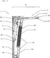
In
In
Für den Gewichtsausgleich ist der Torflügel
Wie der
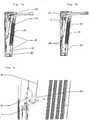
Wie den
Wie der
An dem unteren Ende der Federanordnung
In
Ferner weist die Bodenkonsole mit Fangvorrichtung
Versagt nun die Verbindungseinrichtung
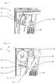
In den
Das Getriebe
Versuche haben gezeigt, dass der Verschleiß des aus Kunststoff gefertigten Zahnrads
Gemäß einer weiteren Ausführungsform können auch beide Zahnräder des Getriebes
In der dargestellten Ausführungsform ist die erste Kopplungseinrichtung
Die zweite Kopplungseinrichtung
Wie der Vorderansicht
Wie den
Wie ferner der Seitenansicht
In den
Das Hebelsystem
Durch die Spannung in dem Drahtseil
Versagt nun der erste Verbindungsabschnitt
Claims (20)
Translated fromGermanPriority Applications (2)
| Application Number | Priority Date | Filing Date | Title |
|---|---|---|---|
| DE102017200279.4ADE102017200279A1 (en) | 2017-01-10 | 2017-01-10 | Device for balancing a gate |
| EP18150994.4AEP3346081B1 (en) | 2017-01-10 | 2018-01-10 | Device for compensating the weight of a gate |
Applications Claiming Priority (1)
| Application Number | Priority Date | Filing Date | Title |
|---|---|---|---|
| DE102017200279.4ADE102017200279A1 (en) | 2017-01-10 | 2017-01-10 | Device for balancing a gate |
Publications (1)
| Publication Number | Publication Date |
|---|---|
| DE102017200279A1true DE102017200279A1 (en) | 2018-07-12 |
Family
ID=60954891
Family Applications (1)
| Application Number | Title | Priority Date | Filing Date |
|---|---|---|---|
| DE102017200279.4APendingDE102017200279A1 (en) | 2017-01-10 | 2017-01-10 | Device for balancing a gate |
Country Status (2)
| Country | Link |
|---|---|
| EP (1) | EP3346081B1 (en) |
| DE (1) | DE102017200279A1 (en) |
Cited By (1)
| Publication number | Priority date | Publication date | Assignee | Title |
|---|---|---|---|---|
| DE202019100171U1 (en)* | 2019-01-14 | 2020-04-15 | DOCO International B.V. NL | gate |
Citations (4)
| Publication number | Priority date | Publication date | Assignee | Title |
|---|---|---|---|---|
| US4914780A (en)* | 1988-08-02 | 1990-04-10 | Schlegel Corporation | Compound counterbalance and winding systems with zero torque spirals |
| WO1998051899A1 (en)* | 1996-05-09 | 1998-11-19 | Kelley Company, Inc. | Roll-up door |
| WO2005042895A2 (en)* | 2003-10-20 | 2005-05-12 | Altimore Larry J | Door operating mechanism and method of using same |
| DE102015106912A1 (en)* | 2015-05-04 | 2016-11-10 | Carl Stahl Kromer Gmbh | Spring tension with a compression spring |
Family Cites Families (6)
| Publication number | Priority date | Publication date | Assignee | Title |
|---|---|---|---|---|
| US1416071A (en)* | 1919-02-03 | 1922-05-16 | Variety Mfg Company | Closure operator |
| US1722250A (en)* | 1926-06-28 | 1929-07-23 | James H Mckee | Overhead garage door |
| US6189266B1 (en)* | 1999-05-31 | 2001-02-20 | Arthur A. Mihalcheon | Safety brake mechanism for overhead sectional door |
| US7296607B2 (en)* | 2004-10-27 | 2007-11-20 | Overhead Door Corporation | Side mount counterbalance system for upward acting door |
| DE202011001511U1 (en)* | 2011-01-14 | 2011-04-28 | Käuferle GmbH & Co. KG | door construction |
| ITMI20120440A1 (en)* | 2012-03-21 | 2013-09-22 | Metallurg Luigi Pessina Acciai S P A | BALANCING DEVICE FOR DOOR LIFTING SYSTEMS |
- 2017
- 2017-01-10DEDE102017200279.4Apatent/DE102017200279A1/enactivePending
- 2018
- 2018-01-10EPEP18150994.4Apatent/EP3346081B1/enactiveActive
Patent Citations (4)
| Publication number | Priority date | Publication date | Assignee | Title |
|---|---|---|---|---|
| US4914780A (en)* | 1988-08-02 | 1990-04-10 | Schlegel Corporation | Compound counterbalance and winding systems with zero torque spirals |
| WO1998051899A1 (en)* | 1996-05-09 | 1998-11-19 | Kelley Company, Inc. | Roll-up door |
| WO2005042895A2 (en)* | 2003-10-20 | 2005-05-12 | Altimore Larry J | Door operating mechanism and method of using same |
| DE102015106912A1 (en)* | 2015-05-04 | 2016-11-10 | Carl Stahl Kromer Gmbh | Spring tension with a compression spring |
Cited By (1)
| Publication number | Priority date | Publication date | Assignee | Title |
|---|---|---|---|---|
| DE202019100171U1 (en)* | 2019-01-14 | 2020-04-15 | DOCO International B.V. NL | gate |
Also Published As
| Publication number | Publication date |
|---|---|
| EP3346081B1 (en) | 2022-05-25 |
| EP3346081A1 (en) | 2018-07-11 |
Similar Documents
| Publication | Publication Date | Title |
|---|---|---|
| DE19713458B4 (en) | Gate with a Zugseileinrichtung | |
| EP1264065B1 (en) | Rolling door | |
| DE102012111611A1 (en) | Roller shutter with a door leaf in the form of a flexible curtain | |
| DE3508175C2 (en) | ||
| WO2015140302A1 (en) | Elevator comprising balance rope tensioning device | |
| EP3346081B1 (en) | Device for compensating the weight of a gate | |
| EP2476838B1 (en) | Door construction | |
| EP3658734A1 (en) | Door system | |
| EP2045425B1 (en) | Single-leaf overhead gate and pre-tensioning device therefor | |
| DE102017123493A1 (en) | Lower door member with folding roll holder | |
| DE102012210584A1 (en) | sliding door system | |
| EP3464766A2 (en) | Overhead folding system and locking device, drive device and frame therefor | |
| DE102007050053A1 (en) | Drive mechanism for opening and closing garage door, includes drive rope wound on drive drum, with door-operating ropes wound on drums carried by common torsion shaft | |
| DE10101560A1 (en) | Door of interlinked elements running along sectional guide rail including curved section, traction mechanism, counterweight, pre-tensioning arrangement and deflector. | |
| DE102015200633A1 (en) | door construction | |
| DE10150000A1 (en) | Single-panel swing door, with an up-and-over overhead opening movement, has a single torsion spring for the hollow spring torsion shaft for weight compensation and a spring for the safety pawl tensed by rotation of its coils | |
| DE202012011518U1 (en) | Bauaufzug | |
| EP1671917A1 (en) | Elevator system with shaftdoor and locking device | |
| DE1584241C (en) | Weight compensation device for a gate wing that can be swiveled overhead into an open position close to the ceiling | |
| EP4382704A1 (en) | Assembly for mounting gates | |
| DE1584241B1 (en) | Weight compensation device for a door leaf that can be pivoted overhead into an open position close to the ceiling | |
| DE102017000231A1 (en) | Drive system for a door leaf | |
| DE10325236A1 (en) | Sectional door for installation in e.g. garages and industrial buildings, has tappets provided on sides of each door section and each motorized pulling unit installed within curvature of each door side rail | |
| DE102012107286B4 (en) | Rolling door with a counterweight compensation device | |
| EP4279697A1 (en) | Door with drive device |
Legal Events
| Date | Code | Title | Description |
|---|---|---|---|
| R163 | Identified publications notified | ||
| R012 | Request for examination validly filed |