DE102017125678A1 - Magnetic field applicator for magnetic field treatment of persons on a treatment couch and / or a treatment chair - Google Patents
Magnetic field applicator for magnetic field treatment of persons on a treatment couch and / or a treatment chairDownload PDFInfo
- Publication number
- DE102017125678A1 DE102017125678A1DE102017125678.4ADE102017125678ADE102017125678A1DE 102017125678 A1DE102017125678 A1DE 102017125678A1DE 102017125678 ADE102017125678 ADE 102017125678ADE 102017125678 A1DE102017125678 A1DE 102017125678A1
- Authority
- DE
- Germany
- Prior art keywords
- treatment
- magnetic field
- magnetic
- field applicator
- magnetic coil
- Prior art date
- Legal status (The legal status is an assumption and is not a legal conclusion. Google has not performed a legal analysis and makes no representation as to the accuracy of the status listed.)
- Withdrawn
Links
- 238000011282treatmentMethods0.000titleclaimsabstractdescription105
- 238000006073displacement reactionMethods0.000claimsdescription17
- 238000004804windingMethods0.000description9
- 230000000638stimulationEffects0.000description5
- 238000011161developmentMethods0.000description3
- 238000013461designMethods0.000description2
- 230000000694effectsEffects0.000description2
- 238000000034methodMethods0.000description2
- 210000002027skeletal muscleAnatomy0.000description2
- BUHVIAUBTBOHAG-FOYDDCNASA-N(2r,3r,4s,5r)-2-[6-[[2-(3,5-dimethoxyphenyl)-2-(2-methylphenyl)ethyl]amino]purin-9-yl]-5-(hydroxymethyl)oxolane-3,4-diolChemical compoundCOC1=CC(OC)=CC(C(CNC=2C=3N=CN(C=3N=CN=2)[C@H]2[C@@H]([C@H](O)[C@@H](CO)O2)O)C=2C(=CC=CC=2)C)=C1BUHVIAUBTBOHAG-FOYDDCNASA-N0.000description1
- 206010053236Mixed incontinenceDiseases0.000description1
- 206010046543Urinary incontinenceDiseases0.000description1
- 230000036982action potentialEffects0.000description1
- 230000005540biological transmissionEffects0.000description1
- 244000309466calfSpecies0.000description1
- 230000007423decreaseEffects0.000description1
- 208000037265diseases, disorders, signs and symptomsDiseases0.000description1
- 239000003814drugSubstances0.000description1
- 238000005516engineering processMethods0.000description1
- 238000011156evaluationMethods0.000description1
- 230000004907fluxEffects0.000description1
- 230000036541healthEffects0.000description1
- 238000011835investigationMethods0.000description1
- 238000002653magnetic therapyMethods0.000description1
- 208000024714major depressive diseaseDiseases0.000description1
- 230000007246mechanismEffects0.000description1
- 210000003205muscleAnatomy0.000description1
- 230000037191muscle physiologyEffects0.000description1
- 210000003903pelvic floorAnatomy0.000description1
- 210000004197pelvisAnatomy0.000description1
- 210000001428peripheral nervous systemAnatomy0.000description1
- 230000035479physiological effects, processes and functionsEffects0.000description1
- 230000001144postural effectEffects0.000description1
- 230000001850reproductive effectEffects0.000description1
- 230000001225therapeutic effectEffects0.000description1
- 238000002560therapeutic procedureMethods0.000description1
- 238000011491transcranial magnetic stimulationMethods0.000description1
- 238000002604ultrasonographyMethods0.000description1
Images


Classifications
- A—HUMAN NECESSITIES
- A61—MEDICAL OR VETERINARY SCIENCE; HYGIENE
- A61N—ELECTROTHERAPY; MAGNETOTHERAPY; RADIATION THERAPY; ULTRASOUND THERAPY
- A61N2/00—Magnetotherapy
- A61N2/004—Magnetotherapy specially adapted for a specific therapy
- A—HUMAN NECESSITIES
- A61—MEDICAL OR VETERINARY SCIENCE; HYGIENE
- A61N—ELECTROTHERAPY; MAGNETOTHERAPY; RADIATION THERAPY; ULTRASOUND THERAPY
- A61N2/00—Magnetotherapy
- A61N2/02—Magnetotherapy using magnetic fields produced by coils, including single turn loops or electromagnets
Landscapes
- Health & Medical Sciences (AREA)
- Engineering & Computer Science (AREA)
- Biomedical Technology (AREA)
- Nuclear Medicine, Radiotherapy & Molecular Imaging (AREA)
- Radiology & Medical Imaging (AREA)
- Life Sciences & Earth Sciences (AREA)
- Animal Behavior & Ethology (AREA)
- General Health & Medical Sciences (AREA)
- Public Health (AREA)
- Veterinary Medicine (AREA)
- Magnetic Treatment Devices (AREA)
- Accommodation For Nursing Or Treatment Tables (AREA)
Abstract
Translated fromGerman
Description
Translated fromGermanDie Erfindung betrifft einen Magnetfeldapplikator zur Magnetfeldbehandlung von Personen auf einer Behandlungsliege und/oder einem Behandlungsstuhl mit mindestens einer Magnetspule.The invention relates to a magnetic field applicator for magnetic field treatment of persons on a treatment table and / or a treatment chair with at least one magnetic coil.
Der Einsatz hochintensiver dynamischer Magnetfelder zur Erzeugung von Aktionspotentialen im zentralen aber auch peripheren Nervensystem ist in der Medizin von wachsendem Interesse. So ist die Transkranielle Magnetstimulation TMS bereits ein anerkanntes Verfahren in der Behandlung therapieresistenter Major Depressions. Mit der Transpelvinen Magnetstimulation TPM zeichnet sich eine wirksame Therapieoption in der Behandlung von Harninkontinenzen bis hin zur reproduktiven Beckengesundheit und von Haltungsschäden ab.The use of high-intensity dynamic magnetic fields to generate action potentials in the central but also peripheral nervous system is of increasing interest in medicine. Transcranial magnetic stimulation TMS is already a recognized procedure in the treatment of therapy-resistant major depressions. The Transpelvinen Magnetic Stimulation TPM is an effective treatment option for the treatment of urinary incontinence, reproductive pelvic health and postural disorders.
Zur Durchführung der Transpelvinen Magnetstimulation TPM steht ein Medizintechniksystem (PelviCenter) zur Verfügung, welches sich z.B. seit Frühjahr 2010 im Beckenbodenzentrum der Chirurgischen Klinik Bogenhausen in der studienmäßigen Evaluierung befindet. Das PelviCenter knüpft dabei an das grundsätzliche Wirkprinzip einer Magnetstimulation des Beckens an, zu dem die Datenbank Pubmed (Medline) schon über 50 klinische Studien mit teilweise starken Therapieeffekten in der Behandlung einer Stress-, Drang- oder Mischinkontinenz indexiert. Auffällig ist dabei, das sich die jeweiligen Studiendesigns zur Reizkonfiguration weitgehend ähneln und Erkenntnisse zur Trainingsphysiologie der Skelettmuskulatur offensichtlich nicht berücksichtigt wurden. Da es sich bei der komplexen Schichtarchitektur des Beckenbodens aber um Skelettmuskeln handelt, erscheint es notwendig, Stimulationseffekte im Hinblick auf den Einsatz optimaler Reizparameter zu quantifizieren. Die Prof. Dr. Fischer AG hat deshalb eine Grundlagenstudie an der Universität der Bundeswehr in München-Neubiberg, Institut für Sportwissenschaften und Sport1, durchführen lassen, denen bereits Untersuchungen der magnetstimulatorischen Reizschwelle an der Wadenmuskulatur unter Ultraschallkontrolle vorausgegangen waren.For the implementation of the transpelvirus magnetic stimulation TPM, a medical technology system (PelviCenter) is available which can be used e.g. since spring 2010 in the pelvic floor center of the surgical clinic Bogenhausen in the study-based evaluation is located. The PelviCenter is based on the principle of magnetic stimulation in the pelvis, to which the Pubmed database (Medline) already indexes more than 50 clinical trials, some of which have strong therapeutic effects in the treatment of stress, urgency or mixed incontinence. It is striking that the respective study designs for the stimulus configuration are largely similar and findings on the physiology of skeletal muscle physiology obviously were not taken into account. However, as the complex layer architecture of the pelvic floor is skeletal muscle, it seems necessary to quantify stimulation effects with regard to the use of optimal stimulus parameters. The Prof. Dr. Fischer AG has therefore carried out a baseline study at the University of the Federal Armed Forces in Munich-Neubiberg, Institute of Sports Science and Sport1, which had already been preceded by investigations of the magnetic stimulation threshold on the calf muscles under ultrasound control.
Eine Behandlungsliege zur Magnettherapie ist beispielsweise mit dem Gegenstand der
Die
Problem bei Hochstrom-Magnetbehandlungen ist, dass bisher aus Kostengründen nur eine einzige Magnetspule verwendet werden konnte, die in der Regel in der Sitzfläche des Behandlungsstuhls oder im Mittenbereich einer Behandlungsliege angeordnet war, was mit dem Nachteil verbunden ist, dass der Einsatzbereich und die Reichweite des verwendeten Magnetfeldes beschränkt war. Es war beispielsweise nicht möglich, gezielt den Beinbereich der Person oder den Oberkörperbereich der Person zu behandeln, weil die bisher bekannten Magnetspulen ortsunveränderbar im Behandlungsstuhl oder der Behandlungsliege angeordnet waren.The problem with high-current magnetic treatments is that, for cost reasons, only a single magnetic coil could be used, which was usually arranged in the seat of the treatment chair or in the middle of a treatment couch, which is associated with the disadvantage that the application area and the range of used magnetic field was limited. For example, it was not possible to specifically treat the leg area of the person or the upper body area of the person because the previously known magnetic coils were arranged in the treatment chair or the treatment table so that they could not be changed in place.
Der Erfindung liegt deshalb die Aufgabe zugrunde, einen Magnetfeldapplikator der eingangs genannten Art so weiterzubilden, dass der Anwendungsbereich des Magnetfeldapplikators über die gesamte Länge der Behandlungsliege oder des Behandlungsstuhls gegeben ist.The invention is therefore based on the object, a magnetic field applicator of the type mentioned in such a way that the scope of the magnetic field applicator over the entire length of the treatment table or the treatment chair is given.
Zur Lösung der gestellten Aufgabe ist die Erfindung durch die technische Lehre des Anspruches 1 gekennzeichnet.To solve the problem, the invention is characterized by the technical teaching of
Merkmal der Erfindung ist, dass lediglich eine Magnetspule vorhanden ist, die mindestens teilweise über die Länge der Behandlungsliege und/oder des Behandlungsstuhls längsverschiebbar ausgebildet ist.A feature of the invention is that only a magnetic coil is provided, which is at least partially longitudinally displaceable over the length of the treatment couch and / or the treatment chair.
Der Gegenstand des Anspruches 1 betrifft demnach einen Magnetfeldapplikator, bei dem eine ortsveränderbare Magnetspule vorhanden ist, die mindestens teilweise über die Länge der Behandlungsliege und/oder des Behandlungsstuhls längsverschiebbar ausgebildet ist. Dies bedeutet in einer ersten Ausführungsform, dass die Magnetspule beispielsweise im Mittenbereich der Behandlungsliege und/oder des Behandlungsstuhls angeordnet ist und dort (nur) im Mittenbereich auch verschiebbar ist.The subject matter of
Nach einer anderen Ausführung ist vorgesehen, dass eine solche Magnetspule (nur) im Kopfbereich und/oder im Beinbereich der Behandlungsliege oder des Behandlungsstuhls angeordnet ist und nur auf diesem Bereich längsverschiebbar ist.According to another embodiment, it is provided that such a magnet coil (only) is arranged in the head area and / or in the leg area of the treatment bed or the treatment chair and is longitudinally displaceable only in this area.
Dieser allgemeine Erfindungsgedanke beansprucht demnach die Verschiebbarkeit einer Magnetspule in bestimmten Bereichen einer Behandlungsliege und/oder eines Behandlungsstuhls.This general concept of the invention therefore claims the displaceability of a magnetic coil in certain areas of a treatment couch and / or a treatment chair.
Der erstgenannte Erfindungsgedanke kann deshalb auch mehrere Magnetspulen betreffen, wobei jede der Magnetspulen in ihrem Bereich (z.B. Mittenbereich oder im Kopfbereich) längsverschiebbar angeordnet ist.The former inventive idea can therefore also relate to a plurality of magnetic coils, each of the magnetic coils being arranged so as to be longitudinally displaceable in its region (for example center region or in the head region).
In einer Weiterbildung dieses Erfindungsgegenstandes ist nach den Gegenständen der Ansprüche 2 und 3 jedoch vorgesehen, dass nur eine einzige Magnetspule vorhanden ist, die über die gesamte Länge der Behandlungsliege und/oder des Behandlungsstuhls längsverschiebbar ausgebildet ist. In a development of this subject invention, however, according to the objects of
Anstatt der Verwendung einer einzigen Magnetspule, die nur in einem bestimmten Bereich der Behandlungsliege oder des Behandlungsstuhls längsverschiebbar ist oder auch anstatt der weiteren Ausführungsform, dass mehrere Magnetspulen nach dem Gegenstand des Anspruches 1 verwendet werden, die jedoch auch nur in den ihnen zugeordneten Bereich längsverschiebbar sind, beansprucht nunmehr der Erfindungsgegenstand nach dem Ansprüchen 2 und 3, dass eine einzige Magnetspule vorhanden ist, die über die gesamte Länge der Behandlungsliege und/oder des Behandlungsstuhls längsverschiebbar ausgebildet ist.Instead of using a single magnetic coil which is longitudinally displaceable only in a certain area of the treatment couch or the treatment chair or instead of the further embodiment that a plurality of magnetic coils are used according to the subject of
Damit ist es erstmals möglich, eine Hochstrom-Behandlung mit einem einzigen Generator für eine einzige Magnetfeldspule vorzusehen, deren Anwendungsbereich sich über die gesamte Länge der Behandlungsliege erstreckt.This makes it possible for the first time to provide a high-current treatment with a single generator for a single magnetic field coil, the scope of which extends over the entire length of the treatment couch.
Der Begriff „gesamte Länge“ muss nicht identisch sein mit der Länge der Behandlungsliege oder der wirksamen Länge des Behandlungsstuhls, weil es nur darauf ankommt, möglichst alle Körperbereiche der zu behandelnden Person von dem Magnetfeld durchsetzen zu lassen. Daher kann die Verschiebungslänge der Magnetspule kürzer sein als die „gesamte Länge der Behandlungsliege“, weil es ausreicht, die Verschiebungslänge der Magnetspule so zu wählen, dass sichergestellt ist, dass alle zu beaufschlagenden Körperteile der zu behandelnden Person auch von dem Magnetfeld der einzigen Magnetspule durchdrungen werden.The term "total length" need not be identical to the length of the treatment couch or the effective length of the treatment chair, because it is important only to allow all body areas of the person to be treated to be penetrated by the magnetic field. Therefore, the displacement length of the solenoid coil can be shorter than the "entire length of the treatment couch", because it is sufficient to choose the displacement length of the solenoid so as to ensure that all body parts of the person to be treated are also penetrated by the magnetic field of the single solenoid coil become.
Die Flussdichte des Magnetfeldes nimmt sehr stark mit dem Abstand von der magnetfelderzeugenden Oberfläche der Spule ab.The flux density of the magnetic field decreases very much with the distance from the magnetic field generating surface of the coil.
Daher wird es in einer Weiterführung der Erfindung vorgeschlagen, dass die Oberkante der Magnetspule mit der Ebene der Liegefläche annähernd fluchtet, so dass stets dafür gesorgt ist, dass die zu behandelnde Person praktisch mit ihrer der Liegefläche zugewandten Körperoberfläche auf der Oberseite der Magnetspule aufliegt.Therefore, it is proposed in a continuation of the invention that the upper edge of the magnetic coil is approximately flush with the plane of the lying surface, so that it is always ensured that the person to be treated practically rests with its lying surface facing the body surface on the top of the solenoid.
Es kann sogar vorgesehen sein, dass die Liegefläche durchbrochen ist und im Bereich dieses Durchbruchs die längenverschiebbare Magnetspule angeordnet ist, um einen möglichst dichten Kontakt der Magnetspule mit den Körperoberflächen der darauf liegenden Person zu ermöglichen.It can even be provided that the lying surface is pierced and in the region of this opening the length-displaceable magnetic coil is arranged in order to allow the closest possible contact of the magnetic coil with the body surfaces of the person lying on it.
Mit der Verwendung einer einzigen Magnetspule, die mit einem einzigen Generator zusammenarbeitet, ist eine kostengünstige Behandlung aller Körperteile einer auf der Behandlungsliege liegenden oder einer auf dem Behandlungsstuhl sitzenden Person möglich, weil erfindungsgemäß vorgesehen ist, dass die Magnetspule über den gesamten Behandlungsbereich der Behandlungsliege oder des Behandlungsstuhls verschiebbar ausgebildet ist.With the use of a single solenoid coil, which cooperates with a single generator, a cost-effective treatment of all body parts of lying on the treatment table or a person sitting on the chair is possible because the invention provides that the magnetic coil over the entire treatment area of the treatment couch or the Dental chair is designed to be displaceable.
Ab einem ersten Lösungsvorschlag der Erfindung ist es vorgesehen, dass die Längsverschiebung der Magnetspule mit einer drehend angetriebenen Spindelstange erfolgt, deren Längsachse parallel zur Mittenlängsachse der Liege oder des Stuhls ausgerichtet ist und die mindestens eine Spindelmutter durchgreift, die mit der Magnetspule verbunden ist.From a first proposed solution of the invention, it is provided that the longitudinal displacement of the solenoid takes place with a rotationally driven spindle rod whose longitudinal axis is aligned parallel to the central longitudinal axis of the deck or the chair and which passes through at least one spindle nut which is connected to the magnetic coil.
Mit der Drehung der Spindelstange wird damit die Magnetspule, welche mit der Spindelmutter verbunden ist, entlang der Spindelstange in Längsrichtung der Liege oder des Stuhls bewegt, und auf diese Weise kann die Magnetspule an jede beliebige Stelle der Liege oder des Behandlungsstuhls verbracht werden.With the rotation of the spindle rod so that the solenoid, which is connected to the spindle nut, along the spindle rod in the longitudinal direction of the deck or the chair moves, and in this way the magnetic coil can be spent at any point of the bed or the treatment chair.
In einer bevorzugten Ausgestaltung ist die Magnetspule in einer Kassette angeordnet, und die Spindelmutter ist an der Kassette angeordnet, so dass eine kompakte Anordnung gewährleistet ist.In a preferred embodiment, the magnetic coil is arranged in a cassette, and the spindle nut is arranged on the cassette, so that a compact arrangement is ensured.
In einer anderen Ausgestaltung der Erfindung kann es vorgesehen sein, dass die Längsverschiebung der Magnetspule (oder der Kassette, in der die Magnetspule angeordnet ist) mit einem in der Länge veränderbaren Zugseil erfolgt.In another embodiment of the invention, it may be provided that the longitudinal displacement of the magnetic coil (or the cassette in which the magnetic coil is arranged) takes place with a traction cable which is variable in length.
In einer dritten Ausgestaltung kann es vorgesehen sein, dass die Längsverschiebung der Magnetspule mit einem Antriebsmotor erfolgt, der in der die Magnetspule aufnehmenden Kassette angeordnet ist und der beidseitig angeordnete Ritzel antreibt, welche sich auf den mit Zahnstangen versehenen Führungsschienen an der Behandlungsliege abwälzen.In a third embodiment, it may be provided that the longitudinal displacement of the solenoid takes place with a drive motor which is arranged in the magnetic coil receiving cassette and drives the pinion arranged on both sides, which roll on the provided with racks guide rails on the treatment couch.
Bei allen Ausführungsformen ist es bevorzugt, wenn die Behandlungsliege aus mehreren Teilen besteht, die gegeneinander abklappbar sind. Somit kann die Behandlungsliege in einen Behandlungsstuhl und umgekehrt umgewandelt werden.In all embodiments, it is preferred if the treatment couch consists of several parts which are hinged against each other. Thus, the treatment couch can be converted into a treatment chair and vice versa.
In einer bevorzugten Ausgestaltung bestehen die Behandlungsliege und/oder der Behandlungsstuhl aus mindestens einem schwenkbaren Kopfteil, das mit einem Mittelteil schwenkbar verbunden ist, wobei ein Mittelteil ein Fußteil schwenkbar ansetzt.In a preferred embodiment, the treatment couch and / or the treatment chair consist of at least one pivotable head part, which is pivotally connected to a central part, wherein a central part attaches a foot part pivotally.
Erfindungsgemäß soll die verschiebbar angetriebene Magnetspule alle Teile dieser Behandlungsliege oder des Behandlungsstuhls erreichen und ist somit erfindungsgemäß sowohl in dem Kopfteil, als auch in dem Mittelteil, als auch in dem Fußteil verschiebbar angetrieben.According to the invention, the displaceably driven magnetic coil should reach all parts of this treatment couch or the treatment chair and is thus according to the invention driven displaceably both in the head part, as well as in the middle part, as well as in the foot part.
Die Erfindung ist nicht auf die Längsverschiebbarkeit einer oder mehrerer Magnetspulen beschränkt. Es kann in einer Weiterbildung vorgesehen sein, dass die Magnetspulen auch querverschiebbar und/oder drehbar ausgebildet sind.The invention is not limited to the longitudinal displacement of one or more magnetic coils. It may be provided in a development that the magnetic coils are also designed to be transversely displaceable and / or rotatable.
Ebenso ist es in einer Weiterbildung vorgesehen, dass die eine oder mehreren Magnetspulen um eine horizontale Schwenkachse herum abklappbar ausgebildet sind.Likewise, it is provided in a development that the one or more magnetic coils are designed hinged around a horizontal pivot axis.
Bei der Verwendung eines Magnetfeldapplikators in Form eines Behandlungsstuhls kann es durch eine geeignete Mechanik zusätzlich vorgesehen sein, dass beim Herunterfahren des Fußteiles der Behandlungsstuhl vorne automatisch hoch gefahren wird, damit das Fußteil länger gemacht werden kann.When using a magnetic field applicator in the form of a dental chair, it may be additionally provided by a suitable mechanism that is automatically raised when driving down the foot of the chair front, so that the foot can be made longer.
Der Erfindungsgegenstand der vorliegenden Erfindung ergibt sich nicht nur aus dem Gegenstand der einzelnen Patentansprüche, sondern auch aus der Kombination der einzelnen Patentansprüche untereinander.The subject of the present invention results not only from the subject matter of the individual claims, but also from the combination of the individual claims with each other.
Alle in den Unterlagen, einschließlich der Zusammenfassung offenbarten Angaben und Merkmale, insbesondere die in den Zeichnungen dargestellte räumliche Ausbildung, werden als erfindungswesentlich beansprucht, soweit sie einzeln oder in Kombination gegenüber dem Stand der Technik neu sind.All information and features disclosed in the documents, including the abstract, in particular the spatial design shown in the drawings, are claimed to be essential to the invention insofar as they are novel individually or in combination with respect to the prior art.
Im Folgenden wird die Erfindung anhand von lediglich einen Ausführungsweg darstellenden Zeichnungen näher erläutert. Hierbei gehen aus den Zeichnungen und ihrer Beschreibung weitere erfindungswesentliche Merkmale und Vorteile der Erfindung hervor.In the following the invention will be explained in more detail with reference to drawings showing only one embodiment. Here are from the drawings and their description further features essential to the invention and advantages of the invention.
Es zeigen:
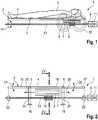
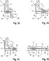
1 : schematisiert die Seitenansicht einer ersten Ausführungsform eines Magnetfeldapplikators in der Art einer Behandlungsliege2 : schematisiert die Seitenansicht der Behandlungsliege nach1 mit Darstellung weiterer Einzelheiten3 : die Draufsicht auf die Behandlungsliege nach2 4 : der Schnitt durch die Behandlungsliege nach IV-IV nach2 und3 5 : eine gegenüber4 abgewandelte Ausführungsform6 : eine weitere gegenüber4 und5 abgewandelte Ausführungsform7 : eine vierte Ausführungsform einer Behandlungsliege oder eines Behandlungsstuhls im Schnitt gemäß VII-VII in8 8 : die Draufsicht auf die Anordnung nach7 9-11 : die Darstellung der verschiedenen Schwenkpositionen einer Behandlungsliege oder eines Behandlungsstuhls mit unterschiedlichen Verschiebungsorten der Magnetspule12-15 : piktogramm-artige Darstellung der verschiedenen Verschiebepositionen der Spule in Verbindung mit verschiedenen Schwenklagen der Behandlungsliege
1 : Schematically illustrates the side view of a first embodiment of a magnetic field applicator in the manner of a treatment couch2 : schematizes the side view of the treatment table1 with further details3 : the top view of the treatment table after2 4 : the section through the treatment couch after IV-IV after2 and3 5 : one opposite4 modified embodiment6 : another opposite4 and5 modified embodiment7 a fourth embodiment of a treatment couch or a treatment chair in section according to VII-VII in8th 8th : the top view of the arrangement after7 9-11 : the representation of the various pivotal positions of a treatment couch or a treatment chair with different displacement locations of the magnetic coil12-15 : pictogram-like representation of the various displacement positions of the coil in conjunction with different pivoting positions of the treatment table
In
Die Liegefläche
Die Behandlungsliege
Somit ist der Kopfteil
An der Unterseite des Rahmens, welcher die Liegefläche
Als Beispiel ist angegeben, dass der Magnetspule ein den Körper der Person durchsetzendes Magnetfeld
Der längsverschiebbare Antrieb der Kassette
Das eine Ende der Spindelstange
Auf diese Weise ist die Spindelstange
Gemäß
Die Spindelstange
Die Abknickung sollte jedoch erst dann erfolgen, wenn die Kassette
Gleiches gilt auch für den Verschiebeantrieb der Kassette
Die Ausführungsform nach
Eine solche Ausführung ist in Draufsicht in
Die Kassette
Ansonsten gelten für die gleichen Teile die gleichen Bezugszeichen.Otherwise, the same reference numerals apply to the same parts.
Die
Ebenso ist dargestellt, dass eine einzige, mittige Spindelstange
In Abweichung vom Ausführungsbeispiel nach
Die
Auf diese Weise kann auf Zugmittel verzichtet werden, weil der Kassette
Die
Dort ist erkennbar, dass an der die Magnetspule
Jede der Wickelwellen
Somit erfolgt eine Bewegung der Kassette
Anstatt der Anordnung von zwei Motor-Getriebeanordnungen
Es ist auch noch dargestellt, dass die Kassette
Die Laufflächen
Wie eingangs ausgeführt, kann eine solche Führungsanordnung auch in Verbindung mit dem autonomen Fahrantrieb der Kassette
Die
In der Behandlungssituation nach
Bei einer Längsverschiebung der Kassette
In analoger Weise kann aufgrund des längsverschieblichen Antriebes der Kassette
In der vorstehenden Beschreibung wurde lediglich eine Längsverschiebung der Kassette
In einer Weiterbildung der Erfindung kann es auch vorgesehen sein, dass die Kassette
Ebenso kann es vorgesehen sein, die Magnetspule und/oder die Kassette, welche die Magnetspule aufnimmt, um eine vertikale Achse herum drehbar zu gestalten.It may also be provided to make the magnetic coil and / or the cassette which accommodates the magnetic coil rotatable about a vertical axis.
Es wurde bei der Durchführung von Doppelblindstudien festgestellt, dass Personen, die mit dem Magnetfeldapplikator
Um derartige Doppelblindstudien objektiv zu gestalten, kann es vorgesehen sein, dass die Magnetspule
Die Abklappbarkeit der Magnetspule
Die
In
Die Kassette
Es kann vorgesehen sein, dass die Kassette
In
In diesem Fall ist es möglich, die Kassette
Auch in diesem Fall kann somit die Kassette
Die
Die
BezugszeichenlisteLIST OF REFERENCE NUMBERS
- 11
- MagnetfeldapplikatorMagnetic field
- 22
- Behandlungsliegetreatment table
- 33
- Personperson
- 44
- Liegeflächelying area
- 55
- Gelenk (Fuß-)Joint (foot)
- 66
- Gelenk (Kopf-)Joint (head)
- 77
- Kassettecassette
- 88th
- Magnetspulesolenoid
- 99
- Getriebetransmission
- 1010
- MagnetfeldapplikatorMagnetic field
- 1111
- Motorengine
- 1212
- Behandlungsliegetreatment table
- 1313
- Spindelstangespindle rod
- 1414
- Pfeilrichtungarrow
- 1515
- Spindelmutterspindle nut
- 1616
- Stützesupport
- 1717
- Kopfteilheadboard
- 1818
- Mittelteilmidsection
- 1919
- Fußteilfootboard
- 2020
- Pfeilrichtungarrow
- 2121
- Pfeilrichtungarrow
- 2222
- Lagerwarehouse
- 2323
- Lagerwarehouse
- 2424
- Knickstellekink
- 2525
- Pfeilrichtungarrow
- 2626
- Pfeilrichtungarrow
- 2727
- Spindelmutterspindle nut
- 2828
- Spindelstangespindle rod
- 2929
- Abstanddistance
- 3030
- Magnetfeldmagnetic field
- 3131
- Stützesupport
- 3232
- Rollerole
- 3434
- Stützwinkelsupport bracket
- 3535
- Laufflächetread
- 3636
- Wellewave
- 3737
- Wickelwellewinding shaft
- 3838
- Wickeltrommelwinding drum
- 3939
- Zugseilrope
- 4040
- Pfeilrichtung
40' arrow40 ' - 4141
- Lagerwarehouse
- 4242
- Behandlungsstuhldental chair
- 4343
- Antriebsmotordrive motor
- 4444
- Antriebswelledrive shaft
- 4545
- Ritzelpinion
- 4646
- Zahnstangerack
- 4747
- Führungsschieneguide rail
ZITATE ENTHALTEN IN DER BESCHREIBUNG QUOTES INCLUDE IN THE DESCRIPTION
Diese Liste der vom Anmelder aufgeführten Dokumente wurde automatisiert erzeugt und ist ausschließlich zur besseren Information des Lesers aufgenommen. Die Liste ist nicht Bestandteil der deutschen Patent- bzw. Gebrauchsmusteranmeldung. Das DPMA übernimmt keinerlei Haftung für etwaige Fehler oder Auslassungen.This list of the documents listed by the applicant has been generated automatically and is included solely for the better information of the reader. The list is not part of the German patent or utility model application. The DPMA assumes no liability for any errors or omissions.
Zitierte PatentliteraturCited patent literature
- DE 10110365 B4 [0004]DE 10110365 B4 [0004]
- DE 102012012149 A1 [0004]DE 102012012149 A1 [0004]
- DE 102014001185 A1 [0004]DE 102014001185 A1 [0004]
- DE 102013014913 B4 [0005]DE 102013014913 B4 [0005]
Claims (12)
Translated fromGermanPriority Applications (3)
| Application Number | Priority Date | Filing Date | Title |
|---|---|---|---|
| DE102017125678.4ADE102017125678A1 (en) | 2017-11-03 | 2017-11-03 | Magnetic field applicator for magnetic field treatment of persons on a treatment couch and / or a treatment chair |
| ES18203733TES2829387T3 (en) | 2017-11-03 | 2018-10-31 | Device for the magnetic field treatment of people on a treatment table and / or a treatment chair |
| EP18203733.3AEP3479872B1 (en) | 2017-11-03 | 2018-10-31 | Device for magnetic field treatment of people in a treatment bed and/or treatment chair |
Applications Claiming Priority (1)
| Application Number | Priority Date | Filing Date | Title |
|---|---|---|---|
| DE102017125678.4ADE102017125678A1 (en) | 2017-11-03 | 2017-11-03 | Magnetic field applicator for magnetic field treatment of persons on a treatment couch and / or a treatment chair |
Publications (1)
| Publication Number | Publication Date |
|---|---|
| DE102017125678A1true DE102017125678A1 (en) | 2019-05-09 |
Family
ID=64048940
Family Applications (1)
| Application Number | Title | Priority Date | Filing Date |
|---|---|---|---|
| DE102017125678.4AWithdrawnDE102017125678A1 (en) | 2017-11-03 | 2017-11-03 | Magnetic field applicator for magnetic field treatment of persons on a treatment couch and / or a treatment chair |
Country Status (3)
| Country | Link |
|---|---|
| EP (1) | EP3479872B1 (en) |
| DE (1) | DE102017125678A1 (en) |
| ES (1) | ES2829387T3 (en) |
Cited By (9)
| Publication number | Priority date | Publication date | Assignee | Title |
|---|---|---|---|---|
| US12029905B2 (en) | 2020-05-04 | 2024-07-09 | Btl Healthcare Technologies A.S. | Device and method for unattended treatment of a patient |
| US12064163B2 (en) | 2021-10-13 | 2024-08-20 | Btl Medical Solutions A.S. | Methods and devices for aesthetic treatment of biological structures by radiofrequency and magnetic energy |
| US12076576B2 (en) | 2019-04-11 | 2024-09-03 | Btl Medical Solutions A.S. | Methods and devices for aesthetic treatment of biological structures by radiofrequency and magnetic energy |
| US12109427B2 (en) | 2016-07-01 | 2024-10-08 | Btl Medical Solutions A.S. | Aesthetic method of biological structure treatment by magnetic field |
| US12109426B2 (en) | 2016-05-10 | 2024-10-08 | Btl Medical Solutions A.S. | Aesthetic method of biological structure treatment by magnetic field |
| US12115365B2 (en) | 2021-11-03 | 2024-10-15 | Btl Healthcare Technologies A.S. | Device and method for unattended treatment of a patient |
| US12156689B2 (en) | 2019-04-11 | 2024-12-03 | Btl Medical Solutions A.S. | Methods and devices for aesthetic treatment of biological structures by radiofrequency and magnetic energy |
| US12274494B2 (en) | 2016-08-16 | 2025-04-15 | Btl Healthcare Technologies A.S. | Treatment device |
| US12427307B2 (en) | 2020-05-04 | 2025-09-30 | Btl Healthcare Technologies A.S. | Device and method for unattended treatment of a patient |
Families Citing this family (4)
| Publication number | Priority date | Publication date | Assignee | Title |
|---|---|---|---|---|
| CA3161576A1 (en)* | 2019-12-04 | 2021-06-04 | Kenneth Paulus | Magnetic nerve stimulator |
| EP3988164A1 (en) | 2020-10-21 | 2022-04-27 | Storz Medical AG | Magnetic field therapy device for pelvic floor stimulation |
| DE102021111627A1 (en) | 2021-05-05 | 2022-11-10 | Prof. Dr. Fischer AG | Device for magnetic field stimulation of a user's body tissue |
| WO2023011503A1 (en)* | 2021-08-03 | 2023-02-09 | 南京伟思医疗科技股份有限公司 | Dual-posture smar seat for pelvic floor magnetic stimulation |
Citations (9)
| Publication number | Priority date | Publication date | Assignee | Title |
|---|---|---|---|---|
| WO1991015263A1 (en)* | 1990-04-02 | 1991-10-17 | Holcomb Medical Corporation | Electromagnetic treatment device |
| US5984854A (en)* | 1996-02-15 | 1999-11-16 | Nihon Kohden Corporation | Method for treating urinary incontinence and an apparatus therefor |
| US6213933B1 (en)* | 1998-09-10 | 2001-04-10 | Vernon Wen-Hau Lin | Apparatus and method for functional magnetic stimulation |
| DE102011014291A1 (en)* | 2011-03-17 | 2012-09-20 | Magic Race Llc | Device for extracorporeal magnetic innervation |
| DE10110365B4 (en) | 2001-03-03 | 2013-05-16 | Quanten-Medicine Ag | Device for detecting effects of pulsed magnetic fields on an organism |
| DE102012012149A1 (en) | 2012-06-20 | 2013-12-24 | Quantenmedicine AG | Method and device for machine-assisted pelvic floor training |
| DE102014001185A1 (en) | 2014-01-30 | 2015-07-30 | QRS International AG | Magnetic field application with slotted laminated core for magnetic stimulation of body tissue |
| DE102013014913B4 (en) | 2013-09-03 | 2017-06-08 | QRS International AG | Magnetic field applicator for magnetic stimulation of body tissue |
| DE102016116399A1 (en)* | 2016-09-01 | 2018-03-01 | Iskra Medical D.O.O. | Sitting or lying device for a magnetic field therapy |
Family Cites Families (3)
| Publication number | Priority date | Publication date | Assignee | Title |
|---|---|---|---|---|
| DE3137455A1 (en)* | 1981-09-21 | 1983-03-24 | Walter 7440 Nürtingen Weiler | Device for sound-magnetic field therapy |
| CA2006319C (en)* | 1989-11-24 | 1995-01-24 | Dragon Susic | Magnetic massage therapy device |
| DE102008029415B4 (en)* | 2008-06-23 | 2014-05-22 | Axel Muntermann | Device for magnetic field therapy |
- 2017
- 2017-11-03DEDE102017125678.4Apatent/DE102017125678A1/ennot_activeWithdrawn
- 2018
- 2018-10-31EPEP18203733.3Apatent/EP3479872B1/enactiveActive
- 2018-10-31ESES18203733Tpatent/ES2829387T3/enactiveActive
Patent Citations (9)
| Publication number | Priority date | Publication date | Assignee | Title |
|---|---|---|---|---|
| WO1991015263A1 (en)* | 1990-04-02 | 1991-10-17 | Holcomb Medical Corporation | Electromagnetic treatment device |
| US5984854A (en)* | 1996-02-15 | 1999-11-16 | Nihon Kohden Corporation | Method for treating urinary incontinence and an apparatus therefor |
| US6213933B1 (en)* | 1998-09-10 | 2001-04-10 | Vernon Wen-Hau Lin | Apparatus and method for functional magnetic stimulation |
| DE10110365B4 (en) | 2001-03-03 | 2013-05-16 | Quanten-Medicine Ag | Device for detecting effects of pulsed magnetic fields on an organism |
| DE102011014291A1 (en)* | 2011-03-17 | 2012-09-20 | Magic Race Llc | Device for extracorporeal magnetic innervation |
| DE102012012149A1 (en) | 2012-06-20 | 2013-12-24 | Quantenmedicine AG | Method and device for machine-assisted pelvic floor training |
| DE102013014913B4 (en) | 2013-09-03 | 2017-06-08 | QRS International AG | Magnetic field applicator for magnetic stimulation of body tissue |
| DE102014001185A1 (en) | 2014-01-30 | 2015-07-30 | QRS International AG | Magnetic field application with slotted laminated core for magnetic stimulation of body tissue |
| DE102016116399A1 (en)* | 2016-09-01 | 2018-03-01 | Iskra Medical D.O.O. | Sitting or lying device for a magnetic field therapy |
Cited By (11)
| Publication number | Priority date | Publication date | Assignee | Title |
|---|---|---|---|---|
| US12109426B2 (en) | 2016-05-10 | 2024-10-08 | Btl Medical Solutions A.S. | Aesthetic method of biological structure treatment by magnetic field |
| US12151120B2 (en) | 2016-05-10 | 2024-11-26 | Btl Medical Solutions A.S. | Aesthetic method of biological structure treatment by magnetic field |
| US12109427B2 (en) | 2016-07-01 | 2024-10-08 | Btl Medical Solutions A.S. | Aesthetic method of biological structure treatment by magnetic field |
| US12274494B2 (en) | 2016-08-16 | 2025-04-15 | Btl Healthcare Technologies A.S. | Treatment device |
| US12076576B2 (en) | 2019-04-11 | 2024-09-03 | Btl Medical Solutions A.S. | Methods and devices for aesthetic treatment of biological structures by radiofrequency and magnetic energy |
| US12156689B2 (en) | 2019-04-11 | 2024-12-03 | Btl Medical Solutions A.S. | Methods and devices for aesthetic treatment of biological structures by radiofrequency and magnetic energy |
| US12029905B2 (en) | 2020-05-04 | 2024-07-09 | Btl Healthcare Technologies A.S. | Device and method for unattended treatment of a patient |
| US12311170B2 (en) | 2020-05-04 | 2025-05-27 | Btl Healthcare Technologies A.S. | Device and method for unattended treatment of a patient |
| US12427307B2 (en) | 2020-05-04 | 2025-09-30 | Btl Healthcare Technologies A.S. | Device and method for unattended treatment of a patient |
| US12064163B2 (en) | 2021-10-13 | 2024-08-20 | Btl Medical Solutions A.S. | Methods and devices for aesthetic treatment of biological structures by radiofrequency and magnetic energy |
| US12115365B2 (en) | 2021-11-03 | 2024-10-15 | Btl Healthcare Technologies A.S. | Device and method for unattended treatment of a patient |
Also Published As
| Publication number | Publication date |
|---|---|
| EP3479872A1 (en) | 2019-05-08 |
| EP3479872B1 (en) | 2020-08-12 |
| ES2829387T3 (en) | 2021-05-31 |
Similar Documents
| Publication | Publication Date | Title |
|---|---|---|
| DE102017125678A1 (en) | Magnetic field applicator for magnetic field treatment of persons on a treatment couch and / or a treatment chair | |
| DE602004006866T2 (en) | DEVICE WITH A MOVABLE LAY FOR STUDYING PERSONS | |
| EP1711227B1 (en) | Device for treating using magnetic fields | |
| DE69133318T2 (en) | Device for treating a body organ using magnetic field therapy | |
| DE60215380T2 (en) | MEDICAL IMAGING SYSTEM | |
| DE68918678T2 (en) | Bed with lying surface, at least partly in the form of a keyboard. | |
| EP2296754B1 (en) | Apparatus for magnetic field therapy | |
| EP2686064A1 (en) | Device for extracorporeal magnetic innervation | |
| DE8620535U1 (en) | Patient positioning table | |
| DE3305692A1 (en) | Adjustable bed | |
| EP2515999A1 (en) | Treatment device using magnetic fields | |
| DE2010121A1 (en) | Sickbed | |
| DE9213188U1 (en) | Muscle training device | |
| DE19538175C2 (en) | Operating table for animals, especially large animals | |
| DE102011051937A1 (en) | A pelvic support device for receiving at least one tension, and the use thereof, and a pad with a pelvic support device for receiving at least one tension, and their use, and method for distracting at least one lower extremity by at least one tension | |
| DE102015122637A1 (en) | Apparatus and method for exercising | |
| DE102018104515B4 (en) | Device for transcranial magnetic stimulation | |
| AT526745B1 (en) | massage table | |
| DE9112809U1 (en) | Device to promote blood circulation in the legs | |
| DE7621395U1 (en) | REMEDIAL GYMNASTICS AND MASSAGE APPARATUS | |
| DE202009008083U1 (en) | Training device for four-legged animals | |
| DE10032814C2 (en) | Whole body treatment device for magnetic therapy | |
| DE4113038A1 (en) | Gymnastic or physiotherapy apparatus - imposes tensile force on spinal column in order to relax it | |
| DE60216732T2 (en) | Device for treating a human body part by means of an electromagnetic field | |
| DE102023130956A1 (en) | Improved massage machine |
Legal Events
| Date | Code | Title | Description |
|---|---|---|---|
| R163 | Identified publications notified | ||
| R119 | Application deemed withdrawn, or ip right lapsed, due to non-payment of renewal fee |