DE102017122704A1 - Device for load transfer - Google Patents
Device for load transferDownload PDFInfo
- Publication number
- DE102017122704A1 DE102017122704A1DE102017122704.0ADE102017122704ADE102017122704A1DE 102017122704 A1DE102017122704 A1DE 102017122704A1DE 102017122704 ADE102017122704 ADE 102017122704ADE 102017122704 A1DE102017122704 A1DE 102017122704A1
- Authority
- DE
- Germany
- Prior art keywords
- trailer
- transfer station
- continuous conveyor
- contact
- trailerzuganhängers
- Prior art date
- Legal status (The legal status is an assumption and is not a legal conclusion. Google has not performed a legal analysis and makes no representation as to the accuracy of the status listed.)
- Withdrawn
Links
- 238000009434installationMethods0.000description6
- 210000000056organAnatomy0.000description4
- 230000013011matingEffects0.000description3
- 238000010276constructionMethods0.000description2
- 230000005611electricityEffects0.000description2
- 238000000034methodMethods0.000description2
- BUHVIAUBTBOHAG-FOYDDCNASA-N(2r,3r,4s,5r)-2-[6-[[2-(3,5-dimethoxyphenyl)-2-(2-methylphenyl)ethyl]amino]purin-9-yl]-5-(hydroxymethyl)oxolane-3,4-diolChemical compoundCOC1=CC(OC)=CC(C(CNC=2C=3N=CN(C=3N=CN=2)[C@H]2[C@@H]([C@H](O)[C@@H](CO)O2)O)C=2C(=CC=CC=2)C)=C1BUHVIAUBTBOHAG-FOYDDCNASA-N0.000description1
- LKJPSUCKSLORMF-UHFFFAOYSA-NMonolinuronChemical compoundCON(C)C(=O)NC1=CC=C(Cl)C=C1LKJPSUCKSLORMF-UHFFFAOYSA-N0.000description1
- 238000004891communicationMethods0.000description1
- 210000003205muscleAnatomy0.000description1
- 210000000689upper legAnatomy0.000description1
Images


Classifications
- B—PERFORMING OPERATIONS; TRANSPORTING
- B60—VEHICLES IN GENERAL
- B60P—VEHICLES ADAPTED FOR LOAD TRANSPORTATION OR TO TRANSPORT, TO CARRY, OR TO COMPRISE SPECIAL LOADS OR OBJECTS
- B60P1/00—Vehicles predominantly for transporting loads and modified to facilitate loading, consolidating the load, or unloading
- B60P1/36—Vehicles predominantly for transporting loads and modified to facilitate loading, consolidating the load, or unloading using endless chains or belts thereon
- B60P1/38—Vehicles predominantly for transporting loads and modified to facilitate loading, consolidating the load, or unloading using endless chains or belts thereon forming the main load-transporting element or part thereof
- B—PERFORMING OPERATIONS; TRANSPORTING
- B65—CONVEYING; PACKING; STORING; HANDLING THIN OR FILAMENTARY MATERIAL
- B65G—TRANSPORT OR STORAGE DEVICES, e.g. CONVEYORS FOR LOADING OR TIPPING, SHOP CONVEYOR SYSTEMS OR PNEUMATIC TUBE CONVEYORS
- B65G65/00—Loading or unloading
- B—PERFORMING OPERATIONS; TRANSPORTING
- B60—VEHICLES IN GENERAL
- B60R—VEHICLES, VEHICLE FITTINGS, OR VEHICLE PARTS, NOT OTHERWISE PROVIDED FOR
- B60R16/00—Electric or fluid circuits specially adapted for vehicles and not otherwise provided for; Arrangement of elements of electric or fluid circuits specially adapted for vehicles and not otherwise provided for
- B60R16/02—Electric or fluid circuits specially adapted for vehicles and not otherwise provided for; Arrangement of elements of electric or fluid circuits specially adapted for vehicles and not otherwise provided for electric constitutive elements
- B60R16/03—Electric or fluid circuits specially adapted for vehicles and not otherwise provided for; Arrangement of elements of electric or fluid circuits specially adapted for vehicles and not otherwise provided for electric constitutive elements for supply of electrical power to vehicle subsystems or for
- B60R16/033—Electric or fluid circuits specially adapted for vehicles and not otherwise provided for; Arrangement of elements of electric or fluid circuits specially adapted for vehicles and not otherwise provided for electric constitutive elements for supply of electrical power to vehicle subsystems or for characterised by the use of electrical cells or batteries
- B—PERFORMING OPERATIONS; TRANSPORTING
- B65—CONVEYING; PACKING; STORING; HANDLING THIN OR FILAMENTARY MATERIAL
- B65G—TRANSPORT OR STORAGE DEVICES, e.g. CONVEYORS FOR LOADING OR TIPPING, SHOP CONVEYOR SYSTEMS OR PNEUMATIC TUBE CONVEYORS
- B65G37/00—Combinations of mechanical conveyors of the same kind, or of different kinds, of interest apart from their application in particular machines or use in particular manufacturing processes
- B65G37/005—Combinations of mechanical conveyors of the same kind, or of different kinds, of interest apart from their application in particular machines or use in particular manufacturing processes comprising two or more co-operating conveying elements with parallel longitudinal axes
- B—PERFORMING OPERATIONS; TRANSPORTING
- B65—CONVEYING; PACKING; STORING; HANDLING THIN OR FILAMENTARY MATERIAL
- B65G—TRANSPORT OR STORAGE DEVICES, e.g. CONVEYORS FOR LOADING OR TIPPING, SHOP CONVEYOR SYSTEMS OR PNEUMATIC TUBE CONVEYORS
- B65G65/00—Loading or unloading
- B65G65/005—Control arrangements
- B—PERFORMING OPERATIONS; TRANSPORTING
- B60—VEHICLES IN GENERAL
- B60P—VEHICLES ADAPTED FOR LOAD TRANSPORTATION OR TO TRANSPORT, TO CARRY, OR TO COMPRISE SPECIAL LOADS OR OBJECTS
- B60P1/00—Vehicles predominantly for transporting loads and modified to facilitate loading, consolidating the load, or unloading
- B60P1/52—Vehicles predominantly for transporting loads and modified to facilitate loading, consolidating the load, or unloading using rollers in the load-transporting element
- B—PERFORMING OPERATIONS; TRANSPORTING
- B62—LAND VEHICLES FOR TRAVELLING OTHERWISE THAN ON RAILS
- B62D—MOTOR VEHICLES; TRAILERS
- B62D53/00—Tractor-trailer combinations; Road trains
- B62D53/005—Combinations with at least three axles and comprising two or more articulated parts
- B—PERFORMING OPERATIONS; TRANSPORTING
- B65—CONVEYING; PACKING; STORING; HANDLING THIN OR FILAMENTARY MATERIAL
- B65G—TRANSPORT OR STORAGE DEVICES, e.g. CONVEYORS FOR LOADING OR TIPPING, SHOP CONVEYOR SYSTEMS OR PNEUMATIC TUBE CONVEYORS
- B65G2203/00—Indexing code relating to control or detection of the articles or the load carriers during conveying
- B65G2203/04—Detection means
- B65G2203/042—Sensors
- B—PERFORMING OPERATIONS; TRANSPORTING
- B65—CONVEYING; PACKING; STORING; HANDLING THIN OR FILAMENTARY MATERIAL
- B65G—TRANSPORT OR STORAGE DEVICES, e.g. CONVEYORS FOR LOADING OR TIPPING, SHOP CONVEYOR SYSTEMS OR PNEUMATIC TUBE CONVEYORS
- B65G2814/00—Indexing codes relating to loading or unloading articles or bulk materials
- B65G2814/03—Loading or unloading means
- B65G2814/0347—Loading or unloading means for cars or linked car-trains with individual load-carriers
- B65G2814/0352—Feeding or discharging devices operated by cars
Landscapes
- Engineering & Computer Science (AREA)
- Mechanical Engineering (AREA)
- Transportation (AREA)
- Intermediate Stations On Conveyors (AREA)
Abstract
Translated fromGermanDescription
Translated fromGermanDie Erfindung betrifft eine Vorrichtung, umfassend eine ortsfeste Übernahmestation und einen mindestens einen Trailerzuganhänger umfassenden Trailerzug zur Übergabe von Lasten von dem Trailerzuganhänger in die ortsfeste Übernahmestation, wobei der Trailerzuganhänger mit einem von einem Motor angetriebenen Stetigförderer zur Aufnahme der Last versehen ist.The invention relates to a device comprising a stationary transfer station and at least one Trailerzuganhänger comprehensive trailer train for transferring loads from the Trailerzuganhänger in the stationary transfer station, the Trailerzuganhänger is provided with a motor driven by a continuous conveyor for receiving the load.
Für den werksinternen Transport von Lasten, beispielsweise Paletten oder Gitterboxen zur Aufnahme von Ladungen, werden in zunehmendem Umfang Trailerzüge eingesetzt, deren Trailerzuganhänger von einem Zugfahrzeug zu den gewünschten Übernahmestationen verfahren werden.For the internal transport of loads, such as pallets or lattice boxes for receiving cargoes, trailer trains are increasingly being used whose trailer train trailer are moved by a towing vehicle to the desired transfer stations.
Aus der
Aus der
Sofern auch an der Übernahmestation ein von einem weiteren Motor angetriebener weiterer Stetigförderer zur Aufnahme der Last angeordnet ist, ist dieser bei bekannten gattungsgemäßen Vorrichtungen zur elektrischen Anbindung an ein Stromnetz eines Gebäudes angeschlossen, in der die Übernahmestation aufgestellt ist.If a further continuous motor driven by a further motor for receiving the load is arranged at the transfer station, this is connected in known generic devices for electrical connection to a power grid of a building in which the transfer station is set up.
Die Versorgung des weiteren Motors der Übernahmestation, der den Stetigförderer der Übernahmestation antreibt, an das Stromnetz eines Gebäudes, führt jedoch zu dem Nachteil, dass bei einer Veränderung des Aufstellungsortes der ortsfesten Übernahmestation, auch an den neuen Aufstellungsort der ortsfesten Übernahmestation ein Stromanschluss gelegt werden muss, um den Motor des Stetigförderers der ortsfesten Übernahmestation mit dem Stromnetz des Gebäudes verbinden zu können. Dies führt bei der Veränderung des Aufstellungsortes der ortsfesten Übernahmestation zu einem hohen Installationsaufwand für den Stromanschluss des Motors des Stetigförderers der Übernahmestation.The supply of the further engine of the transfer station, which drives the continuous conveyor of the transfer station to the power network of a building, however, leads to the disadvantage that when changing the site of the stationary transfer station, also at the new site of the stationary transfer station a power connection must be placed in order to be able to connect the motor of the continuous conveyor of the stationary transfer station with the power network of the building. This results in the change of the site of the stationary transfer station to a high installation cost for the power connection of the motor of the continuous conveyor of the transfer station.
Der vorliegenden Erfindung liegt die Aufgabe zugrunde, eine Vorrichtung der eingangs genannten Gattung zur Verfügung zu stellen, bei der der Aufstellungsort der ortsfesten Übernahmestation verändert werden kann ohne Installationsaufwand für den Stromanschluss des Motors des Stetigförderers der Übernahmestation zu verursachen.The present invention has for its object to provide a device of the type mentioned, in which the site of the stationary transfer station can be changed without installation effort for the power connection of the motor of the continuous conveyor of the transfer station to cause.
Diese Aufgabe wird erfindungsgemäß dadurch gelöst, dass der Motor des Stetigförderers des Trailerzuganhängers von einer Batterie des Trailerzuges versorgt ist und dass an der Übernahmestation ein von einem weiteren Motor angetriebener weiterer Stetigförderer zur Aufnahme der Last angeordnet ist, wobei der weitere Motor des weiterer Stetigförderers an der Übernahmestation in einer vorbestimmten Umschlagposition von der Batterie des Trailerzugs versorgt ist. Durch die erfindungsgemäße elektrische Anbindung des weiteren Motors des weiteren Stetigförderers der ortsfesten Übernahmestation an die Batterie des Trailerzuges ist keine elektrische Anbindung und somit kein Stromanschluss des weiteren Motors des weiteren Stetigförderers der ortsfesten Übernahmestation an ein Stromnetz des Gebäudes erforderlich, so dass keine elektrische Anbindung der Übernahmestation an ein Stromnetz des Gebäudes erforderlich ist. Der Aufstellungsort der ortsfesten Übernahmestation kann somit mit geringem Bauaufwand verändert werden, da an dem neuen Aufstellungsort der ortsfesten Übernahmestation kein Stromanschluss mit dem Stromnetz des Gebäudes und somit kein Installationsaufwand für einen Stromanschluss des Motors des Stetigförderers der Übernahmestation an das Stromnetz des Gebäudes erforderlich ist.This object is achieved in that the engine of the continuous conveyor of Trailerzuganhängers is powered by a battery of the trailer train and that at the transfer station driven by another motor further continuous conveyor for receiving the load is arranged, wherein the further motor of the further continuous conveyor on the Transfer station is supplied in a predetermined envelope position of the battery of the trailer train. Due to the inventive electrical connection of the further motor of the other continuous conveyor of the stationary transfer station to the battery of the trailer train is no electrical connection and thus no power connection of the other motor of further continuous conveyor of the stationary transfer station to a power grid of the building required, so that no electrical connection to the transfer station to a power grid of the building is required. The site of the stationary transfer station can thus be changed with low construction costs, as at the new site of the stationary transfer station there is no power connection to the power network of the building and thus no installation effort is required for a power connection of the engine of the continuous conveyor of the transfer station to the power network of the building.
Gemäß einer vorteilhaften Ausgestaltungsform der Erfindung ist an der Übernahmestation mindestens ein Kontakt vorgesehen, an dem in der vorbestimmten Umschlagposition mindestens ein mit der Batterie des Trailerzugs in Verbindung stehender Kontakt, insbesondere ein Schaltkontakt, des Trailerzuganhängers in Verbindung bringbar ist und dadurch einen Stromkreis zur Spannungsversorgung des weiteren Motors des weiterer Stetigförderers an der Übernahmestation schließt. Mit mindestens einem Kontakt am Trailerzuganhänger, der mit der Batterie des Trailerzugs in Verbindung steht, und einem entsprechenden Gegenkontakt an der ortsfesten Übernahmestation kann auf einfache Weise bei Erreichen der Umschlagposition der mit der Batterie des Trailerzuges in Verbindung stehende Kontakt des Trailerzuganhängers mit dem Kontakt an der Übernahmestation in Verbindung gelangen und eine Verbindung von der Batterie des Trailerzugs zu dem Motor an der Übernahmestation hergestellt werden, um den Motor des Stetigförderers der Übernahmestation zur elektrischen Versorgung mit der Batterie des Trailerzugs zu verbinden.According to an advantageous embodiment of the invention, at least one contact is provided at the transfer station, in which at least one contact with the battery of the trailer train, in particular a switching contact, of the Trailerzuganhängers can be brought into connection in the predetermined envelope position and thereby a circuit for supplying power to the further engine of the further continuous conveyor at the transfer station closes. With at least one contact on Trailerzuganhänger, which is connected to the battery of the trailer train in conjunction, and a corresponding mating contact to the stationary transfer station can easily on reaching the envelope position of the standing in contact with the battery of the trailer train contact the Trailerzuganhängers with the contact on the Transfer terminal and connect a connection from the battery of the trailer train to the engine at the transfer station to connect the engine of the continuous conveyor of the transfer station for electrical supply with the battery of the trailer train.
Vorteilhafterweise ist an der Übernahmestation eine Sensoreinrichtung zum Erkennen der vorbestimmten Umschlagposition des Trailerzuganhängers vorgesehen. Mit einer Sensoreinrichtung kann auf einfache Weise die vorbestimmte Umschlagposition des Trailerzuganhängers an der Übernahmestation erkannt werden.Advantageously, a sensor device for detecting the predetermined envelope position of the Trailerzuganhängers is provided at the transfer station. With a sensor device can be detected at the transfer station in a simple manner, the predetermined envelope position of the Trailerzuganhängers.
Die Batterie des Trailerzugs kann von einer Batterie gebildet sein, die am Trailerzuganhänger angeordnet ist.The battery of the trailer train may be formed by a battery located on the trailer trailer.
Besondere Vorteile ergeben sich, wenn gemäß einer Ausgestaltungsform der Erfindung der Trailerzug ein Zugfahrzeug aufweist und eine Batterie des Zugfahrzeugs die Versorgung des Motors des Stetigförderers des Trailerzuganhängers und die Versorgung des weiteren Motors des weiteren Stetigförderers an der Übernahmestation übernimmt. Eine Batterie des Zugfahrzeugs weist eine entsprechend große Kapazität auf, um den Motor des Stetigförderers des Trailerzuganhängers und den weiteren Motor des weiteren Stetigförderers an der Übernahmestation zu versorgen und kann auf einfache Weise wieder aufgeladen werden. Hierzu ist lediglich an dem Trailerzug eine entsprechende Verbindung der Batterie des Zugfahrzeugs mit den entsprechenden Trailerzuganhängern erforderlich, die einfach mit einem entsprechenden Verbindungskabel hergestellt werden kann.Particular advantages arise when, according to an embodiment of the invention, the trailer train has a towing vehicle and a battery of the towing vehicle takes over the supply of the engine of the continuous conveyor of Trailerzuganhängers and the supply of the further motor of the further continuous conveyor at the transfer station. A battery of the towing vehicle has a correspondingly large capacity to supply the engine of the continuous conveyor of Trailerzuganhängers and the other engine of the other continuous conveyor at the transfer station and can be easily recharged. For this purpose, a corresponding connection of the battery of the towing vehicle with the corresponding Trailerzuganhängern is required only on the trailer train, which can be easily made with a corresponding connection cable.
Gemäß einer vorteilhaften Ausführungsform ist der Kontakt der Übernahmestation auf dem Boden angeordnet. Dies ergibt einen einfachen Installationsaufwand für den Kontakt der Übernahmestation.According to an advantageous embodiment, the contact of the transfer station is arranged on the floor. This results in a simple installation effort for the contact of the transfer station.
Gemäß einer vorteilhaften Ausführungsform ist der Kontakt der Übernahmestation an einer ortsfesten Schiene angebracht. Dies ergibt einen einfachen Installationsaufwand für den Kontakt der Übernahmestation.According to an advantageous embodiment, the contact of the transfer station is mounted on a stationary rail. This results in a simple installation effort for the contact of the transfer station.
Zweckmäßigerweise ist die Sensoreinrichtung ebenfalls an der ortsfesten Schiene angebracht.Conveniently, the sensor device is also attached to the stationary rail.
Besondere Vorteile ergeben sich, wenn der Kontakt der Übernahmestation direkt an der Übernahmestation angebracht ist. Der Kontakt kann beispielsweise formschlüssig an der Übernahmestation angebracht und befestigt sein. Dies ermöglicht eine besonders einfache Veränderung des Aufstellungsortes der ortsfesten Übernahmestation, da die Übernahmestation zusammen mit dem Kontakt an einem neuen Aufstellungsort aufgestellt werden kann, ohne den Kontakt separat auf dem Boden befestigen zu müssen.Special advantages arise when the contact of the transfer station is attached directly to the transfer station. The contact may for example be mounted and secured in a form-fitting manner at the transfer station. This allows a particularly simple change of the site of the stationary transfer station, since the transfer station can be set up together with the contact at a new site without having to attach the contact separately on the ground.
Besondere Vorteile ergeben sich, wenn der Trailerzuganhänger mit zwei horizontal voneinander beabstandeten Kontakten versehen ist, die zur Drehrichtungsumkehr des weiteren Motors des Stetigförderers der Übernahmestation umpolbar sind. Dadurch kann der weitere Stetigförderer der ortsfesten Übernahmestation auf einfache Weise entweder den Entladevorgang oder in umgekehrter Richtung den Beladevorgang ausführen.Particular advantages arise when the Trailerzuganhänger is provided with two horizontally spaced contacts, which are umpolbar to reverse the direction of rotation of the other motor of the continuous conveyor of the transfer station. As a result, the further continuous conveyor of the stationary transfer station can easily perform either the unloading process or the loading process in the reverse direction.
Vorteilhafterweise ist der von dem Motor angetriebene Stetigförderer des Trailerzuganhängers in der Umschlagposition höhengleich zu dem weiteren Stetigförderer der ortsfesten Übernahmestation ausgerichtet. Dadurch kann eine Last auf einfache und sichere Weise höhengleich von dem Trailerzuganhänger auf die ortsfeste Übernahmestation und von der ortsfesten Übernahmestation auf den Trailerzuganhänger bewegt werden.Advantageously, the driven by the motor continuous conveyor of Trailerzuganhängers in the envelope position is aligned equal in height to the other continuous conveyor of the stationary transfer station. As a result, a load can be moved in the same height from the Trailerzuganhänger on the fixed transfer station and from the stationary transfer station on the Trailerzuganhänger in a simple and secure manner.
Der Stetigförderer des Trailerzuganhängers kann als Bandförderer oder als Rollenbahn oder als Kettenförderer ausgebildet sein. Der weitere Stetigförderer der Übernahmestation kann als Bandförderer oder als Rollenbahn oder als Kettenförderer ausgebildet sein. Mit einem Bandförderer oder einer Rollenbahn oder einem Kettenförderer kann eine Last, beispielsweise eine Palette oder eine Gitterbox, auf einfache Weise quer zur Fahrtrichtung des Fahrzeugs des Trailerzuganhängers bewegt werden.The continuous conveyor of Trailerzuganhängers can be designed as a belt conveyor or as a roller conveyor or as a chain conveyor. The further continuous conveyor of the transfer station can be designed as a belt conveyor or as a roller conveyor or as a chain conveyor. With a belt conveyor or a roller conveyor or a chain conveyor, a load, for example a pallet or a lattice box, can be moved in a simple way transversely to the direction of travel of the vehicle of the Trailerzuganhängers.
Gemäß einer vorteilhaften Ausgestaltungsform der Erfindung weist der Trailerzuganhänger einen Hubtisch auf, der mit dem Stetigförderer versehen ist. Mit einem Hubtisch, an dem der Stetigförderer angeordnet ist, kann auf einfache Weise eine höhengleiche Ausrichtung des Stetigförderers des Trailerzuganhängers zu dem weiteren Stetigförderer der ortsfesten Übernahmestation erzielt werden, insbesondere wenn mehrere Übernahmestationen mit unterschiedlichen Höhenniveaus der weiteren Stetigförderer vorhanden sind.According to an advantageous embodiment of the invention, the Trailerzuganhänger a lifting table, which with the continuous conveyor is provided. With a lifting table on which the continuous conveyor is arranged, can be achieved in a simple manner a same height alignment of the continuous conveyor of Trailerzuganhängers to the other continuous conveyor of stationary transfer station, especially if several transfer stations with different height levels of other continuous conveyors are available.
Vorteilhafterweise ist der Hubtisch weiterhin mit dem Kontakt versehen. Durch Absenken des Hubtisches, um den Stetigförderer des Hubtisches höhengleich zu dem weiteren Stetigförderer der Übernahmestation auszurichten, kann somit auch der mit der Batterie des Trailerzugs verbundene Kontakt an dem Hubtisch mit dem Kontakt der ortsfesten Übernahmestation verbunden werden, um den Motor des weiteren Stetigförderers der Übernahmestation mit Strom aus der Batterie des Trailerzugs anzutreiben.Advantageously, the lift table is still provided with the contact. By lowering the lift table to align the continuous conveyor of the lift table height equal to the other continuous conveyor the transfer station, thus connected to the battery of the trailer train contact can be connected to the lift table with the contact of the stationary transfer station to the engine of the other continuous conveyor the transfer station powered by electricity from the battery of the trailer train.
Bevorzugt ist der Hubtisch mittels eines Huborgans relativ zu einem Fahrwerk des Trailerzuganhängers höhenverstellbar ist.Preferably, the lifting table is height adjustable by means of a lifting member relative to a chassis of the Trailerzuganhängers.
Vorteile ergeben sich hierbei, wenn in der vorbestimmten Umschlagposition beim Absenken des Hubtisches der mit der Batterie des Trailerzugs in Verbindung stehende Kontakt des Trailerzuganhängers an dem Kontakt der Übernahmestation anschlägt. In der vorbestimmten Umschlagposition kann somit beim Absenken des Hubtisches in eine Übergabestellung mindestens ein mit der Batterie des Trailerzugs in Verbindung stehender Kontakt, insbesondere ein Schaltkontakt, des Trailerzuganhängers an dem Kontakt der Übernahmestation anschlagen und dadurch den Stromkreis zur Spannungsversorgung des weiteren Motors des weiterer Stetigförderers an der Übernahmestation schließen. Mit mindestens einem Kontakt am Hubtisch des Trailerzuganhängers, der mit der Batterie des Trailerzugs in Verbindung steht, und einem entsprechenden Gegenkontakt an der ortsfesten Übernahmestation kann auf einfache Weise bei Erreichen der Umschlagposition und Absenken des Hubtisches der mit der Batterie des Trailerzuges in Verbindung stehende Kontakt am Hubtisch des Trailerzuganhängers mit dem Kontakt an der Übernahmestation in Verbindung gelangen und eine Verbindung von der Batterie des Trailerzugs zu dem Motor an der Übernahmestation hergestellt werden, um den Motor des Stetigförderers der Übernahmestation zur elektrischen Versorgung mit der Batterie des Trailerzugs zu verbinden.Benefits arise here, if in the predetermined envelope position when lowering the lifting table of standing in contact with the battery of the trailer train in contact with the Trailerzuganhängers abuts the contact of the transfer station. In the predetermined envelope position, therefore, when the lifting table is lowered into a transfer position, at least one contact associated with the battery of the trailer train, in particular a switching contact, of the trailer trailer trailer can strike against the contact of the transfer station and thereby supply the power supply circuit to the further motor of the further continuous conveyor Close the transfer station. With at least one contact on the lift table of the Trailerzuganhängers, which is in contact with the battery of the trailer train, and a corresponding mating contact on the stationary transfer station can easily on reaching the envelope position and lowering the lift table in contact with the battery of the trailer train in contact The trailer lift trailer lift table contacts the pickup station contact and a connection is made from the trailer train battery to the engine at the transfer station to connect the engine of the continuous conveyor to the takeover station for powering the trailer train battery.
Der Trailerzuganhänger hat gemäß einer vorteilhaften Ausführungsform der Erfindung einen den Hubtisch bildenden oder diesen aufnehmenden Tragrahmen. Der Hubtisch kann somit auf einem Tragrahmen angeordnet sein oder direkt von dem Tragrahmen des Trailerzuganhängers gebildet sein.The Trailerzuganhänger has according to an advantageous embodiment of the invention, a lifting table forming or receiving this support frame. The lifting table can thus be arranged on a support frame or be formed directly from the support frame of the Trailerzuganhängers.
Gemäß einer vorteilhaften Ausgestaltungsform der Erfindung weist der Trailerzuganhänger einen mit einem Fahrwerk versehenen Tragrahmen auf, der mit dem Stetigförderer versehen ist. Der Trailerzuganhänger ist somit als starrer Anhänger ohne Hubtisch ausgebildet, der einen besonders einfachen Aufbau aufweist. Mit einem derartigen Trailerzuganhänger kann auf einfache Weise eine höhengleiche Ausrichtung des Stetigförderers des Trailerzuganhängers zu dem weiteren Stetigförderer der ortsfesten Übernahmestation erzielt werden, insbesondere wenn mehrere Übernahmestationen mit jeweils gleichem Höhenniveau der weiteren Stetigförderer vorhanden sind.According to an advantageous embodiment of the invention, the trailer trailer on a provided with a chassis support frame, which is provided with the continuous conveyor. The Trailerzuganhänger is thus designed as a rigid trailer without lifting table, which has a particularly simple structure. With such a Trailerzuganhänger can be achieved in a simple way a height equal orientation of the continuous conveyor of Trailerzuganhängers to the other continuous conveyor of the stationary transfer station, especially if several transfer stations each with the same height level of the other continuous conveyor are available.
Vorteilhaferweise ist hierbei der Kontakt an dem Tragrahmen höhenverstellbar angeordnet und mittels eines Huborgans relativ zum Tragrahmen des Trailerzuganhängers höhenverstellbar. Durch Absenken des Kontaktes relativ zu dem mit dem Stetigförderer versehen Tragrahmen kann somit auf einfache Weise der mit der Batterie des Trailerzugs verbundene Kontakt des Trailerzuganhängers mit dem Kontakt der ortsfesten Übernahmestation verbunden werden, um den Motor des weiteren Stetigförderers der Übernahmestation mit Strom aus der Batterie des Trailerzugs anzutreiben. In der vorbestimmten Umschlagposition kann somit beim Absenken des Kontaktes der mit der Batterie des Trailerzugs in Verbindung stehender Kontakt, insbesondere ein Schaltkontakt, des Trailerzuganhängers an dem Kontakt der Übernahmestation anschlagen und dadurch den Stromkreis zur Spannungsversorgung des weiteren Motors des weiterer Stetigförderers an der Übernahmestation schließen. Mit mindestens einem höhenverstellbar am Tragrahmen angeordneten Kontakt des Trailerzuganhängers, der mit der Batterie des Trailerzugs in Verbindung steht, und einem entsprechenden Gegenkontakt an der ortsfesten Übernahmestation kann somit auf einfache Weise bei Erreichen der Umschlagposition und Absenken des Kontaktes der mit der Batterie des Trailerzuges in Verbindung stehende Kontakt des Trailerzuganhängers mit dem Kontakt an der Übernahmestation in Verbindung gelangen und eine Verbindung von der Batterie des Trailerzugs zu dem Motor an der Übernahmestation hergestellt werden, um den Motor des Stetigförderers der Übernahmestation zur elektrischen Versorgung mit der Batterie des Trailerzugs zu verbinden.Advantageously, in this case the contact on the support frame is arranged vertically adjustable and height adjustable by means of a lifting member relative to the support frame of the Trailerzuganhängers. By lowering the contact relative to the support frame provided with the continuous conveyor can thus be easily connected to the battery of the Trailerzugs contact the Trailerzuganhängers with the contact of the stationary transfer station to the engine of the other continuous conveyor the transfer station with power from the battery Drive trailer train. In the predetermined envelope position can thus abut when lowering the contact of standing in contact with the battery of the trailer train contact, especially a switching contact, the Trailerzuganhängers at the contact of the transfer station and thereby close the circuit for powering the other motor of the other continuous conveyor at the transfer station. With at least one height adjustable arranged on the support frame contact of Trailerzuganhängers that is in communication with the battery of the trailer train, and a corresponding mating contact to the stationary transfer station can thus easily on reaching the envelope position and lowering the contact with the battery of the trailer train in combination standing contact of the Trailerzuganhängers come into contact with the contact at the transfer station and a connection made by the battery of the trailer train to the engine at the transfer station to connect the engine of the continuous conveyor of the transfer station for electrical supply to the battery of the trailer train.
Gemäß einer vorteilhaften Weiterbildung der Erfindung ist der Kontakt an einem mittels des Huborgans höhenverstellbaren Träger angeordnet, der mit einer Abstützvorrichtung, insbesondere einer Stützrolle, zum Abstützen des Trailerzuganhängers auf dem Boden versehen ist. Mit der Abstützvorrichtung kann durch deren Absenken auf den Boden insbesondere ein als Einachsanhänger ausgebildeter Trailerzuganhänger, dessen Achse im Wesentlichen mittig angeordnet ist, in der Umschlagposition auf einfache Weise stabilisiert werden.According to an advantageous embodiment of the invention, the contact is arranged on a height-adjustable by means of the lifting member carrier, which is provided with a supporting device, in particular a support roller for supporting the Trailerzuganhängers on the ground. With the support device can by lowering to the ground in particular designed as Einachsanhänger Trailerzuganhänger whose axis substantially is arranged centrally, are stabilized in the envelope position in a simple manner.
Weitere Vorteile ergeben sich, wenn der Träger seitlich an dem Stetigförderer angeordnet ist und in der angehobenen Stellung das Höhenniveau des Stetigförderers überragt. Der Träger bildet somit in der angehobenen Stellung zusätzlich die Funktion eines seitlichen Anschlags, mit dem eine auf dem Stetigförderers des Trailerzuganhängers befindliche Last während der Fahrt des Trailerzugs gegen seitliches Rutschen gesichert werden kann.Further advantages result if the carrier is arranged laterally on the continuous conveyor and projects beyond the height level of the continuous conveyor in the raised position. The carrier thus forms in the raised position additionally the function of a lateral stop, with which a load located on the continuous conveyor of the Trailerzuganhängers can be secured while driving the trailer train against lateral slipping.
Weitere Vorteile und Einzelheiten der Erfindung werden anhand der in den schematischen Figuren dargestellten Ausführungsbeispiele näher erläutert. Hierbei zeigt
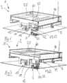
1 eine schematische Frontalansicht einer ersten Ausführungsform einer erfindungsgemäßen Vorrichtung,2 die perspektivische Schrägansicht einer Anlage mit hier vier hintereinander angeordneten Übernahmestationen gemäß der ersten Ausführungsform der erfindungsgemäßen Vorrichtung,3 in vergrößerter Darstellung eine Übernahmevorrichtung gemäß der ersten Ausführungsform der erfindungsgemäßen Vorrichtung ohne Last,4 in vergrößerter Ansicht einen Teil eines Trailerzuganhängers der ersten Ausführungsform der erfindungsgemäßen Vorrichtung in der Umschlagposition bei geöffneten Kontakten,5 eine der4 entsprechende Darstellung mit geschlossenen Kontakten,6 einen Trailerzuganhänger gemäß einer zweiten Ausführungsform der erfindungsgemäßen Vorrichtung mit geöffneten Kontakten,7 einen Trailerzuganhänger gemäß der6 mit geschlossenen Kontakten,8 einen Ausschnitt der6 in einer vergrößerten Darstellung,9 einen Ausschnitt der7 in einer vergrößerten Darstellung,10 eine schematische Frontalansicht der zweiten Ausführungsform der erfindungsgemäßen Vorrichtung mit geöffneten Kontakten und11 eine schematische Frontalansicht der zweiten Ausführungsform der erfindungsgemäßen Vorrichtung mit geschlossenen Kontakten.
1 a schematic frontal view of a first embodiment of a device according to the invention,2 the perspective oblique view of a plant with here four successively arranged transfer stations according to the first embodiment of the device according to the invention,3 in an enlarged view, a transfer device according to the first embodiment of the device according to the invention without load,4 in an enlarged view a part of a Trailerzuganhängers the first embodiment of the device according to the invention in the envelope position with opened contacts,5 one of the4 corresponding representation with closed contacts,6 a Trailerzuganhänger according to a second embodiment of the device according to the invention with opened contacts,7 a Trailerzuganhänger according to the6 with closed contacts,8th a section of the6 in an enlarged view,9 a section of the7 in an enlarged view,10 a schematic frontal view of the second embodiment of the device according to the invention with opened contacts and11 a schematic front view of the second embodiment of the device according to the invention with closed contacts.
Die in den
Der Trailerzug
Wie das Ausführungsbeispiel der
Der Tragrahmen
Der Tragrahmen
Der elektrische Motor
Die ortsfeste Übernahmestation
In dem Ausführungsbeispiel der
Bei dem Trailerzuganhänger
Die Huborgane
Zur elektrischen Versorgung des elektrischen Motors
An der ortsfesten Übernahmestation
Der Trailerzuganhänger
Auf dem horizontalen Schenkel
Die Kontakte
Wenn der Trailerzuganhänger
Für die Abgabe einer L von dem Trailerzuganhänger
Wenn die Sensoren
Der Tragrahmen
In dem Ausführungsbeispiel der
In dem Ausführungsbeispiel der
Der Trailerzuganhänger
Der Kontakt
Das Huborgan ist bevorzugt als elektrisches Huborgan ausgebildet, das von der Batterie
Zur elektrischen Versorgung des elektrischen Motors
Die ortsfeste Übernahmestation des Ausführungsbeispiels der
Der Kontakt
Der Träger
Der Kontakt
Wenn der Trailerzuganhänger
Bei dem Ausführungsbeispiel der
Für die Abgabe einer
Wenn die Sensoren
Mit der Erfindung ergeben sich besondere Vorteile:The invention results in particular advantages:
Dadurch dass der weitere Motor
ZITATE ENTHALTEN IN DER BESCHREIBUNG QUOTES INCLUDE IN THE DESCRIPTION
Diese Liste der vom Anmelder aufgeführten Dokumente wurde automatisiert erzeugt und ist ausschließlich zur besseren Information des Lesers aufgenommen. Die Liste ist nicht Bestandteil der deutschen Patent- bzw. Gebrauchsmusteranmeldung. Das DPMA übernimmt keinerlei Haftung für etwaige Fehler oder Auslassungen.This list of the documents listed by the applicant has been generated automatically and is included solely for the better information of the reader. The list is not part of the German patent or utility model application. The DPMA assumes no liability for any errors or omissions.
Zitierte PatentliteraturCited patent literature
- DE 202013102199 U1 [0003]DE 202013102199 U1 [0003]
- DE 202015105184 U1 [0004]DE 202015105184 U1 [0004]
Claims (21)
Translated fromGermanPriority Applications (9)
| Application Number | Priority Date | Filing Date | Title |
|---|---|---|---|
| DE102017122704.0ADE102017122704A1 (en) | 2017-09-29 | 2017-09-29 | Device for load transfer |
| SI201830955TSI3687855T1 (en) | 2017-09-29 | 2018-08-21 | Device for load transfer |
| MX2020001194AMX2020001194A (en) | 2017-09-29 | 2018-08-21 | Device for load transfer. |
| PL18759913.9TPL3687855T3 (en) | 2017-09-29 | 2018-08-21 | Device for load transfer |
| EP18759913.9AEP3687855B1 (en) | 2017-09-29 | 2018-08-21 | Device for load transfer |
| PCT/EP2018/072500WO2019063201A1 (en) | 2017-09-29 | 2018-08-21 | CHARGE TRANSFER DEVICE |
| ES18759913TES2955287T3 (en) | 2017-09-29 | 2018-08-21 | Load transfer device |
| US16/651,967US11364833B2 (en) | 2017-09-29 | 2018-08-21 | Device for load transfer |
| HUE18759913AHUE063087T2 (en) | 2017-09-29 | 2018-08-21 | Device for load transfer |
Applications Claiming Priority (1)
| Application Number | Priority Date | Filing Date | Title |
|---|---|---|---|
| DE102017122704.0ADE102017122704A1 (en) | 2017-09-29 | 2017-09-29 | Device for load transfer |
Publications (1)
| Publication Number | Publication Date |
|---|---|
| DE102017122704A1true DE102017122704A1 (en) | 2019-04-04 |
Family
ID=63405199
Family Applications (1)
| Application Number | Title | Priority Date | Filing Date |
|---|---|---|---|
| DE102017122704.0AWithdrawnDE102017122704A1 (en) | 2017-09-29 | 2017-09-29 | Device for load transfer |
Country Status (9)
| Country | Link |
|---|---|
| US (1) | US11364833B2 (en) |
| EP (1) | EP3687855B1 (en) |
| DE (1) | DE102017122704A1 (en) |
| ES (1) | ES2955287T3 (en) |
| HU (1) | HUE063087T2 (en) |
| MX (1) | MX2020001194A (en) |
| PL (1) | PL3687855T3 (en) |
| SI (1) | SI3687855T1 (en) |
| WO (1) | WO2019063201A1 (en) |
Cited By (3)
| Publication number | Priority date | Publication date | Assignee | Title |
|---|---|---|---|---|
| DE102019118710A1 (en)* | 2019-07-10 | 2021-01-14 | Henrik Bernhard Bennewitz | Method and loading system for loading load carriers in a warehouse |
| AT526695A1 (en)* | 2022-10-31 | 2024-05-15 | Vanilla Automation Consulting Gmbh | Arrangement, transport device, assembly device and method |
| US12017716B2 (en) | 2019-07-16 | 2024-06-25 | Creative Innovations Ag | Vehicle configurator |
Families Citing this family (2)
| Publication number | Priority date | Publication date | Assignee | Title |
|---|---|---|---|---|
| DE102020110257A1 (en)* | 2020-04-15 | 2021-10-21 | Lr Intralogistik Gmbh | System comprising a tugger train and at least one stationary transfer station |
| USD999700S1 (en)* | 2023-04-19 | 2023-09-26 | Feng Cheng | Wheel for cargo lift |
Citations (2)
| Publication number | Priority date | Publication date | Assignee | Title |
|---|---|---|---|---|
| DE202013102199U1 (en) | 2013-05-21 | 2013-06-06 | Lr Intralogistik Gmbh | Trailerzuganhänger |
| DE202015105184U1 (en) | 2015-10-01 | 2016-03-17 | Lr Intralogistik Gmbh | Device for load transfer |
Family Cites Families (26)
| Publication number | Priority date | Publication date | Assignee | Title |
|---|---|---|---|---|
| US3322913A (en)* | 1965-02-17 | 1967-05-30 | Gen Electric | Power coupling mechanism |
| US3998343A (en)* | 1974-12-30 | 1976-12-21 | Fors Vernen E | Cargo moving apparatus for trucks |
| US4286911A (en)* | 1978-02-28 | 1981-09-01 | Litton Systems, Inc. | Semi-automated warehousing system |
| US4541768A (en)* | 1983-10-13 | 1985-09-17 | Fmc Corporation | Container trailer |
| US4792995A (en)* | 1987-08-19 | 1988-12-20 | Caterpillar Industrial Inc. | Bidirectional roller deck control for a self guided vehicle |
| US4944357A (en) | 1989-04-27 | 1990-07-31 | Caterpillar Industrial Inc. | Power transferring arrangement |
| US5202832A (en)* | 1991-01-29 | 1993-04-13 | R. R. Donnelley & Sons Co. | Material handling automation system using portable transfer module |
| US5482425A (en)* | 1991-07-18 | 1996-01-09 | Podd, Jr.; Victor I. | Conveyor sheet cargo container and method |
| KR100191130B1 (en)* | 1992-10-01 | 1999-06-15 | 이도 스스므 | Article transportation system |
| KR970054461U (en)* | 1996-03-26 | 1997-10-13 | LCD Glass Carrying Manual Balance | |
| ITMI20061341A1 (en)* | 2006-07-11 | 2008-01-12 | Fata Spa | SHUTTLE INSILATION TROLLEY AND CONTAINER HANDLING AND STORAGE SYSTEM |
| DE102009016743B4 (en)* | 2009-04-09 | 2014-05-08 | Landtechnisches Lohnunternehmen Ebbecke Gmbh & Co. Kg | Industrial transport vehicle |
| JP5721980B2 (en)* | 2010-09-03 | 2015-05-20 | 株式会社日立製作所 | Automated guided vehicle and travel control method |
| US8509981B2 (en)* | 2011-05-25 | 2013-08-13 | Toyota Motor Engineering & Manufacturing North America, Inc. | Docking stations for automated guided vehicles |
| DE102013003849A1 (en)* | 2013-03-06 | 2014-09-25 | Airbus Operations Gmbh | System for moving loads |
| CN105705441B (en)* | 2013-09-13 | 2018-04-10 | 西姆伯蒂克有限责任公司 | Autonomous transport car, the method for storing and fetching system and selection face being transmitted in the system |
| DE202014101510U1 (en)* | 2014-03-31 | 2015-01-22 | Lr Intralogistik Gmbh | Trailer trailer with support frame for a transport cart |
| DE202015104465U1 (en)* | 2015-08-24 | 2015-10-08 | Lr Intralogistik Gmbh | Trailer trailer with lifting device |
| US10230315B2 (en)* | 2016-05-02 | 2019-03-12 | Kamran Ramezani | Use of battery as the DC power source in portable/expandable or fixed conveyors to drive DC motors |
| DE102016113972A1 (en)* | 2016-07-28 | 2018-02-01 | Lr Intralogistik Gmbh | Tugger trailer and transport system as well as transport methods |
| US10449886B2 (en)* | 2016-11-29 | 2019-10-22 | Revolutionary Truck Systems | Container transfer system |
| DE102017110862A1 (en)* | 2017-05-18 | 2018-11-22 | Lr Intralogistik Gmbh | Tugger trailer for a tugger train |
| US10787108B2 (en)* | 2018-06-29 | 2020-09-29 | Mark Chris Vollmering | Trailer bed mounted load plow system |
| US11235931B2 (en)* | 2019-04-05 | 2022-02-01 | The Raymond Corporation | Conveyor cart alignment systems and methods |
| US11273748B2 (en)* | 2019-09-06 | 2022-03-15 | Meyer Manufacturing Corporation | High throughput forage reloader |
| US11578464B2 (en)* | 2020-06-24 | 2023-02-14 | B & B Metals, Inc. | Tie plate dispenser and method therefore |
- 2017
- 2017-09-29DEDE102017122704.0Apatent/DE102017122704A1/ennot_activeWithdrawn
- 2018
- 2018-08-21ESES18759913Tpatent/ES2955287T3/enactiveActive
- 2018-08-21PLPL18759913.9Tpatent/PL3687855T3/enunknown
- 2018-08-21SISI201830955Tpatent/SI3687855T1/enunknown
- 2018-08-21WOPCT/EP2018/072500patent/WO2019063201A1/ennot_activeCeased
- 2018-08-21USUS16/651,967patent/US11364833B2/enactiveActive
- 2018-08-21EPEP18759913.9Apatent/EP3687855B1/enactiveActive
- 2018-08-21MXMX2020001194Apatent/MX2020001194A/enunknown
- 2018-08-21HUHUE18759913Apatent/HUE063087T2/enunknown
Patent Citations (2)
| Publication number | Priority date | Publication date | Assignee | Title |
|---|---|---|---|---|
| DE202013102199U1 (en) | 2013-05-21 | 2013-06-06 | Lr Intralogistik Gmbh | Trailerzuganhänger |
| DE202015105184U1 (en) | 2015-10-01 | 2016-03-17 | Lr Intralogistik Gmbh | Device for load transfer |
Cited By (4)
| Publication number | Priority date | Publication date | Assignee | Title |
|---|---|---|---|---|
| DE102019118710A1 (en)* | 2019-07-10 | 2021-01-14 | Henrik Bernhard Bennewitz | Method and loading system for loading load carriers in a warehouse |
| US12017716B2 (en) | 2019-07-16 | 2024-06-25 | Creative Innovations Ag | Vehicle configurator |
| EP3999378B1 (en)* | 2019-07-16 | 2024-11-06 | Creative Innovations AG | Vehicle configurator |
| AT526695A1 (en)* | 2022-10-31 | 2024-05-15 | Vanilla Automation Consulting Gmbh | Arrangement, transport device, assembly device and method |
Also Published As
| Publication number | Publication date |
|---|---|
| PL3687855T3 (en) | 2024-04-08 |
| MX2020001194A (en) | 2020-03-20 |
| EP3687855B1 (en) | 2023-06-14 |
| WO2019063201A1 (en) | 2019-04-04 |
| US11364833B2 (en) | 2022-06-21 |
| US20200254916A1 (en) | 2020-08-13 |
| ES2955287T3 (en) | 2023-11-29 |
| SI3687855T1 (en) | 2023-09-29 |
| HUE063087T2 (en) | 2023-12-28 |
| EP3687855A1 (en) | 2020-08-05 |
Similar Documents
| Publication | Publication Date | Title |
|---|---|---|
| DE102017122704A1 (en) | Device for load transfer | |
| EP3150522B9 (en) | Device for load transfer | |
| DE202013102199U1 (en) | Trailerzuganhänger | |
| EP2440431A1 (en) | Heavy-duty ground transportation vehicle, in particular an unmanned heavy-duty transportation vehicle for iso containers | |
| DE102016113972A1 (en) | Tugger trailer and transport system as well as transport methods | |
| DE102014213831A1 (en) | Charging device for an electrically rechargeable vehicle | |
| EP3031658A1 (en) | Charging method for an energy storage device of a vehicle | |
| EP3357741A1 (en) | Device for charging an electrical energy storage device of a vehicle with an electrical drive | |
| DE102012000008A1 (en) | Rail-bound transport equipment for shifting and positioning e.g. steel component used in bridge construction site, has hydraulic shifter for shifting and positioning load accommodation desk along preset direction | |
| DE102016121095A1 (en) | Routenzuganhänger | |
| DE102019129419A1 (en) | Device and method for conductive charging | |
| EP3464019A1 (en) | Verification of the integrity of a train of vehicles | |
| EP3357740B1 (en) | Device for charging an electrical energy storage device of a vehicle with an electrical drive | |
| DE202009005662U1 (en) | Lifting device for lifting loads, in particular vehicles | |
| DE102021108419B4 (en) | AGV based transport logistic module | |
| WO2019224111A1 (en) | Vehicle with a driving module and a load module | |
| DE102015008684A1 (en) | Support frame for a traction battery and holding arrangement of such a traction battery to a body of a vehicle | |
| DE102008024572A1 (en) | Current collecting carriage for use with e.g. container stack crane, has positioning units attached to contact element of carriage such that contact element is positioned to contact element of vehicle for establishing electrical connection | |
| DE102016207988A1 (en) | Transport system and trolley for a transport system | |
| DE102017104751A1 (en) | transport device | |
| EP2433834A1 (en) | Device for securing cargo on a cargo vehicle | |
| DE102012201641A1 (en) | Conveying device e.g. trolley for transporting sheet or plate-like goods such as corrugated board, has drive motor that is arranged in support frames and is connected with conveying elements supported in support construction | |
| EP3357739B1 (en) | Device for charging an electrical energy storage device of a vehicle with an electrical drive | |
| DE102015104611B3 (en) | Device for supporting a load | |
| DE102011121573A1 (en) | Industrial truck for transporting components e.g. motor car component, has line which is provided for supplying electrical power and/or control signals to lifting device, and plug element is arranged by decoupling device |
Legal Events
| Date | Code | Title | Description |
|---|---|---|---|
| R005 | Application deemed withdrawn due to failure to request examination |