DE102017115750A1 - Dysgnathic bone positioning device with separation tool guide device / section - Google Patents
Dysgnathic bone positioning device with separation tool guide device / sectionDownload PDFInfo
- Publication number
- DE102017115750A1 DE102017115750A1DE102017115750.6ADE102017115750ADE102017115750A1DE 102017115750 A1DE102017115750 A1DE 102017115750A1DE 102017115750 ADE102017115750 ADE 102017115750ADE 102017115750 A1DE102017115750 A1DE 102017115750A1
- Authority
- DE
- Germany
- Prior art keywords
- positioning device
- bone positioning
- base body
- bone
- cutting tool
- Prior art date
- Legal status (The legal status is an assumption and is not a legal conclusion. Google has not performed a legal analysis and makes no representation as to the accuracy of the status listed.)
- Withdrawn
Links
- 210000000988bone and boneAnatomy0.000titleclaimsabstractdescription32
- 238000000926separation methodMethods0.000titledescription6
- 238000005299abrasionMethods0.000claimsdescription4
- 230000002265preventionEffects0.000claimsdescription4
- 238000009434installationMethods0.000claimsdescription2
- 238000003801millingMethods0.000description4
- 210000004195gingivaAnatomy0.000description2
- 238000003780insertionMethods0.000description2
- 230000037431insertionEffects0.000description2
- 238000004519manufacturing processMethods0.000description2
- 239000000463materialSubstances0.000description2
- 241000309551Arthraxon hispidusSpecies0.000description1
- 239000000654additiveSubstances0.000description1
- 230000000996additive effectEffects0.000description1
- 230000009286beneficial effectEffects0.000description1
- 238000006243chemical reactionMethods0.000description1
- 230000003247decreasing effectEffects0.000description1
- 239000004053dental implantSubstances0.000description1
- 239000012634fragmentSubstances0.000description1
- 229920001296polysiloxanePolymers0.000description1
- 239000011347resinSubstances0.000description1
- 229920005989resinPolymers0.000description1
Images
Classifications
- A—HUMAN NECESSITIES
- A61—MEDICAL OR VETERINARY SCIENCE; HYGIENE
- A61C—DENTISTRY; APPARATUS OR METHODS FOR ORAL OR DENTAL HYGIENE
- A61C5/00—Filling or capping teeth
- A61C5/007—Dental splints; teeth or jaw immobilisation devices; stabilizing retainers bonded to teeth after orthodontic treatments
- A—HUMAN NECESSITIES
- A61—MEDICAL OR VETERINARY SCIENCE; HYGIENE
- A61B—DIAGNOSIS; SURGERY; IDENTIFICATION
- A61B17/00—Surgical instruments, devices or methods
- A61B17/14—Surgical saws
- A61B17/15—Guides therefor
- A61B17/151—Guides therefor for corrective osteotomy
- A—HUMAN NECESSITIES
- A61—MEDICAL OR VETERINARY SCIENCE; HYGIENE
- A61B—DIAGNOSIS; SURGERY; IDENTIFICATION
- A61B17/00—Surgical instruments, devices or methods
- A61B17/16—Instruments for performing osteoclasis; Drills or chisels for bones; Trepans
- A61B17/17—Guides or aligning means for drills, mills, pins or wires
- A61B17/1739—Guides or aligning means for drills, mills, pins or wires specially adapted for particular parts of the body
- A61B17/176—Guides or aligning means for drills, mills, pins or wires specially adapted for particular parts of the body for the jaw
- A—HUMAN NECESSITIES
- A61—MEDICAL OR VETERINARY SCIENCE; HYGIENE
- A61B—DIAGNOSIS; SURGERY; IDENTIFICATION
- A61B17/00—Surgical instruments, devices or methods
- A61B17/16—Instruments for performing osteoclasis; Drills or chisels for bones; Trepans
- A61B2017/1602—Mills
Landscapes
- Health & Medical Sciences (AREA)
- Life Sciences & Earth Sciences (AREA)
- Surgery (AREA)
- Oral & Maxillofacial Surgery (AREA)
- Dentistry (AREA)
- Veterinary Medicine (AREA)
- General Health & Medical Sciences (AREA)
- Public Health (AREA)
- Animal Behavior & Ethology (AREA)
- Engineering & Computer Science (AREA)
- Nuclear Medicine, Radiotherapy & Molecular Imaging (AREA)
- Orthopedic Medicine & Surgery (AREA)
- Biomedical Technology (AREA)
- Heart & Thoracic Surgery (AREA)
- Medical Informatics (AREA)
- Molecular Biology (AREA)
- Epidemiology (AREA)
- Surgical Instruments (AREA)
- Dental Tools And Instruments Or Auxiliary Dental Instruments (AREA)
Abstract
Translated fromGerman
Description
Translated fromGermanDie Erfindung betrifft eine Knochenpositioniervorrichtung zum Einsatz in der Dysgnathie bei Neupositionierung von Knochenabschnitten zueinander. Solche Knochenabschnitte sind dann üblicherweise Bestandteile eines Oberkiefers oder eines Unterkiefers. Diese Knochenabschnitte sind dann an einer Stelle, an welcher ein Trennwerkzeug eine Trennung vorgenommen hat, vollständig von dem Restknochen getrennt. Die Knochenpositioniervorrichtung weist einen Grundkörper auf, der eine dem Unterkiefer zugewandte Unterseite besitzt, auf der Vertiefungen zum Aufnehmen von unterkieferfesten Navigierhilfen, wie Zähnen oder Gingiva-Abschnitten, vorhanden sind, und weist auch eine gegenüberliegende, dem Oberkiefer zugewandte Oberseite auf, auf der ebenfalls Vertiefungen zum Aufnehmen von oberkieferfesten Navigierhilfen, wie Zähnen oder Gingiva-Abschnitten vorhanden sind. Solche Knochenpositioniervorrichtungen werden von den Fachleuten auch als Splint bezeichnet. Solche Splinte oder Knochenpositioniervorrichtungen sind üblicherweise Kunststoffschienen, mit der intraoperativ, also während der Operation, Ober- und Unterkiefer miteinander verbunden werden, um deren Lage, die angestrebte Verzahnung, sowie die Position der Kondylen / Kiefergelenksköpfchen zu sichern. Um den Unterkiefer in die gewünschte Position zu verbringen wird häufig eine sagittale Osteotomie durchgeführt. Dabei wird jedoch die Trennung frei und ungeführt vorgenommen. Dies führt teilweise dann leider zu einem ungenauen Positionsschnitt.The invention relates to a bone positioning device for use in the Dysgnathie in repositioning of bone sections to each other. Such bone sections are then usually components of an upper jaw or a lower jaw. These bone sections are then completely separated from the residual bone at a location where a separation tool has made a separation. The bone positioning device has a base body which has a bottom side facing the lower jaw, on which recesses for receiving mandibular navigation aids, such as teeth or gingiva sections, are present, and also has an opposite, the upper jaw-facing top, on the wells also for holding upright navigation aids, such as teeth or gingiva sections. Such bone positioning devices are also referred to as splint by those skilled in the art. Such cotter pins or bone positioning devices are usually plastic splints with which intraoperatively, ie during the operation, upper and lower jaws are connected to one another in order to secure their position, the desired toothing and the position of the condylar / mandibular joint heads. In order to place the lower jaw in the desired position, a sagittal osteotomy is often performed. However, the separation is done freely and unguided. Unfortunately, this sometimes leads to an inaccurate positional section.
Es ist dabei die Aufgabe der vorliegenden Erfindung eine Operation schneller, erfolgversprechender und genauer durchzuführen. Insbesondere sollen auch die aus dem Stand der Technik bekannten Nachteile behoben werden. Eine vorzustellende Lösung soll kostengünstig sein, einfach einzusetzen sein und sich im Markt gut durchsetzen können.It is the object of the present invention to perform an operation faster, more promising and more accurate. In particular, the disadvantages known from the prior art should also be eliminated. A solution to be presented should be cost-effective, easy to use and able to prevail in the market well.
Diese Aufgabe wird bei einer gattungsgemäßen Knochenpositioniervorrichtung erfindungsgemäß dadurch gelöst, dass am Grundkörper wenigstens eine Trennwerkzeugführungsvorrichtung angebracht ist, die vorbereitet ist, um ein Trennwerkzeug entlang des gewünschten Positionsschnittes exakt entlang zu führen.This object is achieved in a generic bone positioning according to the invention that at least one separating tool guide device is mounted on the base body, which is prepared to guide a cutting tool along the desired position section exactly along.
Es wird somit am Splint für die Okklusion des Oberkiefers zum Unterkiefer eine seitliche Sägeführung vorgehalten, die im Dysgnathie-Bereich einsetzbar ist. Ein sagittaler Schnitt kann dann nachvollziehbar mit einem Fräser oder einem anderen gewünschten Schnittwerkzeug durchgeführt werden. Dieser Schnitt ist dann präzise.It is thus kept on the splint for the occlusion of the upper jaw to the lower jaw a lateral Sägeführung, which is used in the Dysgnathie area. A sagittal cut can then be made comprehensibly with a milling cutter or another desired cutting tool. This cut is then precise.
Vorteilhafte Ausführungsformen sind in den Unteransprüchen beansprucht und werden nachfolgend näher erläutert.Advantageous embodiments are claimed in the subclaims and are explained in more detail below.
So ist es von Vorteil, wenn die Trennwerkzeugführungsvorrichtung nach außen und/oder innen absteht. Bei einer Vielzahl von Trennwerkzeugführungsvorrichtungen kann eine bestimmte Anzahl nach außen abstehen und eine bestimmte Anzahl nach innen abstehen. Bevorzugt ist es aber, wenn alle Trennwerkzeugführungsvorrichtungen nach außen oder nach innen abstehen. Die Trennwerkzeugführungsvorrichtung soll einen Führungsbereich besitzen, der das Einlegen / Anlegen eines Trennwerkzeuges, wie eines Fräsers oder einer Säge, ermöglicht, um einen 1 mm +/- 20 % starken Schlitz zu fertigen. Die Richtung, kann mit einem Fräser, mit Hilfe des Splints, übertragen werden und die Osteotomie markiert werden. Ausgeführt wird die Osteotomie dann ebenfalls mit einem Fräser. Es kann derselbe Fräser sein.Thus, it is advantageous if the cutting tool guide device projects outwards and / or inwards. In a plurality of cutting tool guide devices, a certain number may protrude outward and protrude inward a certain number. It is preferred, however, if all Trennwerkzeugführungsvorrichtungen protrude outward or inward. The cutting tool guiding device is intended to have a guiding area which allows the insertion / application of a cutting tool, such as a mill or saw, to make a 1 mm +/- 20% slot. The direction can be transferred with a router, with the help of the splint, and the osteotomy can be marked. The osteotomy is then also performed with a milling cutter. It can be the same router.
Wenn die Trennwerkzeugführungsvorrichtung eine Strecke vorgibt, entlang der ein Trennwerkzeug, wie der Fräser oder die Säge, zwangsgeführt ist, so wird ein Verlaufen oder Verrutschen des Trennwerkzeuges wirkungsvoll ausgeschlossen.If the cutting tool guide device specifies a distance along which a cutting tool, such as the milling cutter or the saw, is forcibly guided, running or slipping of the cutting tool is effectively precluded.
Um möglichst schnell den Knochen durchtrennen zu können, ist es von Vorteil, wenn die Strecke vollständig oder abschnittsweise linear / gerade ausgestaltet ist, wobei die Alternative einer kurvigen Ausgestaltung der Strecke ebenfalls denkbar ist, insbesondere um kritische Areale auszusparen. Es ist denkbar, dass die Strecke abschnittsweise linear gestaltet ist und abschnittsweise kurvig ausgestaltet ist. Bei einer kurvigen Ausgestaltung kann eine gleichbleibende Krümmung, eine zunehmende oder abnehmende Krümmung, oder eine Kombination dieser Ausgestaltungen eingesetzt sein.In order to be able to sever the bone as quickly as possible, it is advantageous if the route is completely or partially linear / straight, whereby the alternative of a curved configuration of the route is likewise conceivable, in particular in order to avoid critical areas. It is conceivable that the route is designed in sections linear and is partially curvy configured. In a curved configuration, a constant curvature, an increasing or decreasing curvature, or a combination of these configurations can be used.
Es hat sich bewährt, wenn die Trennwerkzeugführungsvorrichtung einen hufeisenförmigen, U-, C- oder L-förmigen Querschnitt besitzt. Das Einlegen eines Werkzeuges zum Geführt sein in mehreren Raumrichtungen, vorzugsweise drei Raumrichtungen, ist dann die Folge. Während bei den hufeisen-, U-, C- oder L-förmigen Querschnitten immer eine offene Struktur eingesetzt ist, kann jedoch auch eine geschlossene Struktur, etwa nach Art eines Hohlzylinders angedacht werden. Insbesondere ein Hohlzylinder mit einer polygonartigen, elliptischen oder gar kreisrunden Innen- bzw. Außenkontur ist denkbar.It has proven useful if the cutting tool guide device has a horseshoe-shaped, U-, C- or L-shaped cross section. The insertion of a tool to be guided in several spatial directions, preferably three spatial directions, is then the result. While in the horseshoe, U, C or L-shaped cross sections always an open structure is used, however, a closed structure, such as a hollow cylinder may be considered. In particular, a hollow cylinder with a polygonal, elliptical or even circular inner or outer contour is conceivable.
Es hat sich ferner bewährt, wenn ein Vektor entlang der Strecke quer durch eine gedachte Ebene durch die Oberseite und/oder die Unterseite des Grundkörpers verläuft.It has also proven useful when a vector runs along the path across an imaginary plane through the top and / or the bottom of the body.
Ein vorteilhaftes Ausführungsbeispiel ist auch dadurch gekennzeichnet, dass zwei Trennwerkzeugführungsvorrichtungen beiderseits des Grundkörpers vorhanden sind. Eine vollständige Trennung des zu verlagernden Unterkieferbereiches vom Restunterkiefer kann dann schnell geschaffen werden. Für den Oberkiefer gilt dies im übertragenen Sinne. Für die Fertigung ist es zuträglich, wenn die Trennwerkzeugführungsvorrichtung integral / einstückig / einmaterialig mit dem Grundkörper verbunden ist oder aber lösbar, etwa form- und/oder kraftschlüssig mit dem Grundkörper verbunden ist. Im ersten Fall kann ein vollständiges Werkzeug geschaffen werden, das nicht mehr weiter vorbereitet werden muss, wohingegen im zweiten Fall eine bessere Handhabbarkeit die Folge ist. An advantageous embodiment is also characterized in that two Trennwerkzeugführungsvorrichtungen are present on both sides of the body. A complete separation of the mandibular area to be relocated from the lower jaw can then be created quickly. This applies to the upper jaw in the figurative sense. For manufacturing, it is beneficial if the cutting tool guide device is integrally / integrally / einmaterialig connected to the base body or releasably, as positively and / or non-positively connected to the base body. In the first case, a complete tool can be created, which does not need to be further prepared, whereas in the second case better handling is the result.
Wenn zwischen der Trennwerkzeugführungsvorrichtung und dem Grundkörper eine Soll-Bruchstelle vorhanden / ausgebildet ist, so ergeben sich operativ mehr Möglichkeiten des Einsatzes.If a predetermined breaking point is present / formed between the separating tool guiding device and the main body, this results in more operational possibilities for use.
Ebenfalls hat es sich bewährt, wenn am Grundkörper ein Sockel, etwa ein Vier-Kant-Sockel, vorhanden ist, auf den eine gegengleiche Aufnahme an der / in der Trennwerkzeugführungsvorrichtung eingesetzt / angepasst ist.It has also proven useful if a base, such as a four-edge socket, is provided on the base body, on which a counter-identical receptacle on / in the cutting tool guide device is used / adapted.
Es ist von Vorteil, wenn im Bereich einer geplanten Trennwerkzeuganlage ein Abriebverhinderungseinsatz vorhanden ist. Die Präzision des Einsatzes während der Operation wird dadurch erhöht.It is advantageous if an abrasion prevention insert is present in the area of a planned cutting tool installation. The precision of the insert during the operation is thereby increased.
Auch ist es von Vorteil, wenn die Abriebverhinderungseinrichtung aus härterem Material, zumindest oberflächlich / an einem Abschnitt der Oberfläche, aufgebaut ist, als der Grundkörper bzw. der Rest der Trennwerkzeugführungsvorrichtung.It is also advantageous if the abrasion prevention device is made of a harder material, at least superficially / on a portion of the surface, than the main body or the remainder of the separating tool guiding device.
Ein vorteilhaftes Ausführungsbeispiel ist auch dadurch gekennzeichnet, dass der Abriebverhinderungseinsatz in/auf die/den Trennwerkzeugführungsvorrichtung oder in/auf den Grundkörper aufgeclipst oder ein- / aufgeklebt ist.An advantageous embodiment is also characterized in that the abrasion prevention insert is clipped in / on the cutting tool guide device or in / on the base body or glued on /.
Letztlich betrifft die Erfindung also auch den Einsatz der Knochenpositioniervorrichtung derart, dass die Trennwerkzeugführungsvorrichtung als Kulisse wirkt.Ultimately, therefore, the invention also relates to the use of bone positioning such that the cutting tool guide device acts as a backdrop.
Die Erfindung kann auch dadurch weitergebildet werden, dass beim Grundkörper und/oder der Trennwerkzeugführungsvorrichtung Harz / Silikone und/oder ähnliche Werkstoffe eingesetzt ist/sind. Dabei können generative / additive Fertigungsverfahren eingesetzt werden.The invention can also be further developed by using resin / silicones and / or similar materials in the base body and / or the separating tool guiding device. In this case, generative / additive manufacturing processes can be used.
Die dem Trennwerkzeug zugewandte Oberfläche der Trennwerkzeugführungsvorrichtung kann nach Art einer Treppenstufe oder eines rechten Winkels ausgebildet sein oder diese / diesen umfassen. Die Ausrichtung der Trennwerkzeugführungsvorrichtung, insbesondere des der bereits erläuterten Strecke zugeordneten Vektors, wird im Rahmen der virtuellen Planung bereits festgelegt. Somit wird schon während der virtuellen Planung die Ausrichtung vorbestimmt.The cutting tool facing surface of the cutting tool guide device may be formed in the manner of a step or a right angle or include this / these. The orientation of the separating tool guiding device, in particular of the vector associated with the route already explained, is already defined in the context of the virtual planning. Thus, the orientation is already predetermined during the virtual planning.
Als Hintergrund sei an dieser Stelle noch erläutert, dass üblicherweise mehrere Knochenpositioniervorrichtungen eingesetzt werden. Üblicherweise wird im Rahmen der Operation bei noch fehlerhafter Knochenstellung ein so genannter Ist-Zustand-Splint eingesetzt. Auf diesen bezieht sich die vorliegende Erfindung. Der danach eingesetzte Intermediate-Splint oder der danach eingesetzte Final-Splint kann genauso - aber üblicherweise doch anders - gefertigt sein, da hier keine Fräsvorgänge bzw. Trennvorgänge mehr vonnöten sind. Ergo kann die Trennwerkzeugführungsvorrichtung bei diesem Intermediate-Splint oder dem Final-Splint fehlen.As background it should be explained at this point that usually several bone positioning devices are used. Usually, a so-called actual state splint is used in the context of the operation with still faulty bone position. The present invention relates to this. The subsequently used intermediate splint or the subsequently used final splint can be produced in exactly the same way, but usually in a different way, since no more milling processes or separation processes are required here. Ergo, the parting tool guide device may be missing from this intermediate splint or final split pin.
Vorteilhafte Ausführungsformen sind in den Unteransprüchen beansprucht und werden nachfolgend näher erläutert.Advantageous embodiments are claimed in the subclaims and are explained in more detail below.
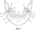
In der einzigen
Die Figur ist lediglich schematischer Natur und dient nur dem Verständnis der Erfindung.The figure is merely schematic in nature and is only for understanding the invention.
In der
Die Knochenpositioniervorrichtung
Auf beiden Seiten des Grundkörpers
BezugszeichenlisteLIST OF REFERENCE NUMBERS
- 11
- Knochenpositioniervorrichtung / Ist-Zustand-SplintBone Positioning Device / Actual State Splint
- 22
- Grundkörperbody
- 33
- Unterseitebottom
- 44
- Oberseitetop
- 55
- Vertiefungdeepening
- 66
- NavigierhilfeNavigierhilfe
- 77
- Unterkieferlower jaw
- 88th
- TrennwerkzeugführungsvorrichtungCutting tool guide apparatus
- 99
- Innenseiteinside
- 1010
- Anlageflächecontact surface
Claims (10)
Translated fromGermanPriority Applications (9)
| Application Number | Priority Date | Filing Date | Title |
|---|---|---|---|
| DE102017115750.6ADE102017115750A1 (en) | 2017-07-13 | 2017-07-13 | Dysgnathic bone positioning device with separation tool guide device / section |
| AU2018300033AAU2018300033B2 (en) | 2017-07-13 | 2018-07-12 | Bone positioning device for dysgnathia having a cutting-tool guide device/section |
| JP2020501139AJP2020526324A (en) | 2017-07-13 | 2018-07-12 | Bone positioning device for mandibular dysgenesis with cutting tool guide device / part |
| PCT/EP2018/068955WO2019012048A1 (en) | 2017-07-13 | 2018-07-12 | BONE POSITIONING DEVICE FOR DYSGNATHY WITH SEPARATE TOOL GUIDE / SECTION |
| RU2020106679ARU2771466C2 (en) | 2017-07-13 | 2018-07-12 | Positioning device for positioning bone in dysgnathia, having guiding device/guiding section for guiding cutting tool |
| EP18742753.9AEP3651681A1 (en) | 2017-07-13 | 2018-07-12 | Bone positioning device for dysgnathia having a cutting-tool guide device/section |
| BR112020000703-0ABR112020000703B1 (en) | 2017-07-13 | 2018-07-12 | BONE POSITIONING DEVICE FOR DYSGNATHY SHOWING A CUTTING TOOL GUIDE DEVICE/SECTION |
| US16/629,704US11357520B2 (en) | 2017-07-13 | 2018-07-12 | Bone positioning device for dysgnathia having a cutting-tool guide |
| CN201880045747.5ACN110891519A (en) | 2017-07-13 | 2018-07-12 | Bone positioning device with separate tool guides/segments for dental malformations |
Applications Claiming Priority (1)
| Application Number | Priority Date | Filing Date | Title |
|---|---|---|---|
| DE102017115750.6ADE102017115750A1 (en) | 2017-07-13 | 2017-07-13 | Dysgnathic bone positioning device with separation tool guide device / section |
Publications (1)
| Publication Number | Publication Date |
|---|---|
| DE102017115750A1true DE102017115750A1 (en) | 2019-01-17 |
Family
ID=62952069
Family Applications (1)
| Application Number | Title | Priority Date | Filing Date |
|---|---|---|---|
| DE102017115750.6AWithdrawnDE102017115750A1 (en) | 2017-07-13 | 2017-07-13 | Dysgnathic bone positioning device with separation tool guide device / section |
Country Status (9)
| Country | Link |
|---|---|
| US (1) | US11357520B2 (en) |
| EP (1) | EP3651681A1 (en) |
| JP (1) | JP2020526324A (en) |
| CN (1) | CN110891519A (en) |
| AU (1) | AU2018300033B2 (en) |
| BR (1) | BR112020000703B1 (en) |
| DE (1) | DE102017115750A1 (en) |
| RU (1) | RU2771466C2 (en) |
| WO (1) | WO2019012048A1 (en) |
Citations (4)
| Publication number | Priority date | Publication date | Assignee | Title |
|---|---|---|---|---|
| US20040166469A1 (en)* | 2002-01-22 | 2004-08-26 | Tremont Timothy J. | Method and apparatus to assist in orthognathic surgery |
| DE102006043204A1 (en)* | 2006-09-11 | 2008-03-27 | Zinser, Jochen Max, Dr. | Method for producing surgical splints, in particular for computer-assisted maxillofacial operations and remodeling osteotomies |
| US20110059413A1 (en)* | 2007-04-20 | 2011-03-10 | Medicim Nv | Method for deriving shape information |
| CH710871A2 (en)* | 2015-03-05 | 2016-09-15 | Lucera Invest Sagl | Bite. |
Family Cites Families (19)
| Publication number | Priority date | Publication date | Assignee | Title |
|---|---|---|---|---|
| US4306866A (en) | 1979-08-27 | 1981-12-22 | Ipco Corporation | Adjustable dental drill guide |
| US7014461B2 (en)* | 2003-01-23 | 2006-03-21 | Tactile Technologies Llc | Hard tissue surface geometry determination |
| JP2008073440A (en)* | 2006-09-25 | 2008-04-03 | Imagunooshisu Kk | Manufacturing method for implant raising guide and guiding block |
| US20110311941A1 (en)* | 2008-11-03 | 2011-12-22 | Tae-Kyoung Yi | Stent including elastic part using for surgical operation of implant |
| US8764441B2 (en)* | 2010-07-21 | 2014-07-01 | John W. Polley | Method and internal apparatus for determining final position of dentate skeleton in orthognathic surgery |
| ES2823723T3 (en)* | 2011-05-26 | 2021-05-10 | Viax Dental Tech Llc | Dental tool and guiding devices |
| US8968321B2 (en)* | 2011-06-30 | 2015-03-03 | Depuy (Ireland) | Patella resection guide with locating features and method of using the same |
| US9361410B2 (en)* | 2012-05-03 | 2016-06-07 | DePuy Synthes Products, Inc. | Surgical guides from scanned implant data |
| CN203089328U (en)* | 2013-03-04 | 2013-07-31 | 张英泽 | Calcar femorale bone cutting locator |
| GB2513148A (en)* | 2013-04-17 | 2014-10-22 | Digital Srl | Surgical guide |
| US10282488B2 (en)* | 2014-04-25 | 2019-05-07 | Biomet Manufacturing, Llc | HTO guide with optional guided ACL/PCL tunnels |
| CN104771231B (en)* | 2015-04-27 | 2016-10-12 | 四川大学 | Guider for orthognathic surgery bone piece displacement and preparation method thereof |
| CN204863356U (en) | 2015-05-07 | 2015-12-16 | 王旭东 | Plastic of chin bone cuts bone conduction board |
| KR101719576B1 (en)* | 2015-06-05 | 2017-04-04 | 연세대학교 산학협력단 | Bimaxillary Orthognathic Y-splint, Manufacturing Method Thereof, Recording Medium Therefor, Manufacturing Apparatus Therefor |
| CN105078586B (en)* | 2015-09-28 | 2017-04-12 | 四川大学 | Digitized template used for orthognathic surgery and manufacturing method thereof |
| CN105686886B (en) | 2016-01-08 | 2018-07-13 | 四川大学 | Subapical osteotomy positioning guide plate and preparation method thereof |
| DE102017202817B3 (en)* | 2017-02-22 | 2018-02-08 | Frank Zastrow | Device for guiding a dental surgical hollow cutter |
| US11007035B2 (en)* | 2017-03-16 | 2021-05-18 | Viax Dental Technologies Llc | System for preparing teeth for the placement of veneers |
| US11504210B2 (en)* | 2018-07-13 | 2022-11-22 | National Dentex, Llc | Dental bone foundation guide with palatal or lingual side gap and freehand surgical guide |
- 2017
- 2017-07-13DEDE102017115750.6Apatent/DE102017115750A1/ennot_activeWithdrawn
- 2018
- 2018-07-12USUS16/629,704patent/US11357520B2/enactiveActive
- 2018-07-12WOPCT/EP2018/068955patent/WO2019012048A1/ennot_activeCeased
- 2018-07-12CNCN201880045747.5Apatent/CN110891519A/enactivePending
- 2018-07-12BRBR112020000703-0Apatent/BR112020000703B1/ennot_activeIP Right Cessation
- 2018-07-12JPJP2020501139Apatent/JP2020526324A/enactivePending
- 2018-07-12EPEP18742753.9Apatent/EP3651681A1/ennot_activeWithdrawn
- 2018-07-12RURU2020106679Apatent/RU2771466C2/enactive
- 2018-07-12AUAU2018300033Apatent/AU2018300033B2/ennot_activeCeased
Patent Citations (4)
| Publication number | Priority date | Publication date | Assignee | Title |
|---|---|---|---|---|
| US20040166469A1 (en)* | 2002-01-22 | 2004-08-26 | Tremont Timothy J. | Method and apparatus to assist in orthognathic surgery |
| DE102006043204A1 (en)* | 2006-09-11 | 2008-03-27 | Zinser, Jochen Max, Dr. | Method for producing surgical splints, in particular for computer-assisted maxillofacial operations and remodeling osteotomies |
| US20110059413A1 (en)* | 2007-04-20 | 2011-03-10 | Medicim Nv | Method for deriving shape information |
| CH710871A2 (en)* | 2015-03-05 | 2016-09-15 | Lucera Invest Sagl | Bite. |
Also Published As
| Publication number | Publication date |
|---|---|
| AU2018300033A1 (en) | 2020-01-30 |
| RU2020106679A3 (en) | 2021-10-20 |
| BR112020000703A2 (en) | 2020-07-14 |
| RU2020106679A (en) | 2021-08-13 |
| RU2771466C2 (en) | 2022-05-04 |
| US11357520B2 (en) | 2022-06-14 |
| EP3651681A1 (en) | 2020-05-20 |
| WO2019012048A1 (en) | 2019-01-17 |
| BR112020000703B1 (en) | 2022-12-27 |
| JP2020526324A (en) | 2020-08-31 |
| US20210085344A1 (en) | 2021-03-25 |
| AU2018300033B2 (en) | 2023-07-13 |
| CN110891519A (en) | 2020-03-17 |
Similar Documents
| Publication | Publication Date | Title |
|---|---|---|
| EP1476084B1 (en) | Saw jig for medical purposes | |
| DE10233808B3 (en) | Bone-cutter for correcting ostetomy has bearing parts each containing a duct, slots meeting at acute angle and holding p iece of bone | |
| EP1901671B1 (en) | Osteosynthesis plate comprising through-openings which are inclined in relation to the plane of the plate | |
| DE4328690B4 (en) | Intervertebral implant for vertebral body blocking and implantation instrument for positioning the intervertebral implant | |
| DE2901962C2 (en) | ||
| DE102015107484A1 (en) | Orthogonal sawing and positioning implant | |
| WO2012140218A1 (en) | Intervertebral implant and insertion device | |
| DE10224005A1 (en) | System for the fixation and reconstruction of bone fractures, especially at the lower jaw, has tools for the right and left hands to bend and cut the bone plates, together with a trocar and screwdriver | |
| DE20309361U1 (en) | Osteosynthesis, especially an angle-stable radius plate, for the surgical treatment of bone fractures | |
| DE2238071B2 (en) | DENTAL JAW IMPLANT | |
| DE202013007361U1 (en) | Instrument set for inserting a basket into the disc space between two vertebral bodies | |
| WO2009146923A1 (en) | Chip-removing tool | |
| EP2964112B1 (en) | Medical tool system | |
| EP2617382B1 (en) | Dental curette | |
| DE102017115750A1 (en) | Dysgnathic bone positioning device with separation tool guide device / section | |
| DE2628929A1 (en) | INTERNAL DENTAL IMPLANT | |
| EP2712571A1 (en) | Hollow reamer for dental purposes | |
| DE9215541U1 (en) | Dental bone splitting and spreading tool | |
| DE102005047097B4 (en) | Surgical profile element, set of surgical profile elements and surgical container to | |
| DE102007045886B4 (en) | Foot surgery bone plate, a wrapping system and fixation system | |
| WO2005077307A1 (en) | Intervertebral implant | |
| DE102010012960A1 (en) | Sleeve-guided tool system for preparing implant bed for positioning implant of teeth of patient, has positioning sleeve inserted and locked in guiding sleeve, and tool retained and guided in guiding sleeve in longitudinally movable manner | |
| DE20304367U1 (en) | Dental implant | |
| EP2606848A1 (en) | Device for positioning holes for an implant | |
| DE102015014795A1 (en) | Saw gauge for introducing at least one saw cut into a bone and use of the saw jig |
Legal Events
| Date | Code | Title | Description |
|---|---|---|---|
| R163 | Identified publications notified | ||
| R005 | Application deemed withdrawn due to failure to request examination |