Movatterモバイル変換


[0]ホーム

URL:


DE102017115024A1 - Drive arrangement for a flap of a motor vehicle - Google Patents

Drive arrangement for a flap of a motor vehicle
Download PDF

Info

Publication number
DE102017115024A1
DE102017115024A1DE102017115024.2ADE102017115024ADE102017115024A1DE 102017115024 A1DE102017115024 A1DE 102017115024A1DE 102017115024 ADE102017115024 ADE 102017115024ADE 102017115024 A1DE102017115024 A1DE 102017115024A1
Authority
DE
Germany
Prior art keywords
drive
spindle drives
spindle
adjustment information
drive control
Prior art date
Legal status (The legal status is an assumption and is not a legal conclusion. Google has not performed a legal analysis and makes no representation as to the accuracy of the status listed.)
Pending
Application number
DE102017115024.2A
Other languages
German (de)
Inventor
Sebastian Schödel
Current Assignee (The listed assignees may be inaccurate. Google has not performed a legal analysis and makes no representation or warranty as to the accuracy of the list.)
Brose Fahrzeugteile SE and Co KG
Original Assignee
Brose Fahrzeugteile SE and Co KG
Priority date (The priority date is an assumption and is not a legal conclusion. Google has not performed a legal analysis and makes no representation as to the accuracy of the date listed.)
Filing date
Publication date
Application filed by Brose Fahrzeugteile SE and Co KGfiledCriticalBrose Fahrzeugteile SE and Co KG
Priority to DE102017115024.2ApriorityCriticalpatent/DE102017115024A1/en
Publication of DE102017115024A1publicationCriticalpatent/DE102017115024A1/en
Pendinglegal-statusCriticalCurrent

Links

Images

Classifications

Landscapes

Abstract

Translated fromGerman

Die Erfindung betrifft eine Antriebsanordnung für eine Klappe (2) eines Kraftfahrzeugs (3), wobei die Antriebsanordnung (1) zwei Spindelantriebe (4a, 4b) mit jeweils einem Antriebsmotor (M1, M2) und eine Antriebssteuerung (6) zur Ansteuerung der Spindelantriebe (4a, 4b) aufweist, wobei die Spindelantriebe (4a, 4b) im montierten Zustand antriebstechnisch mit der Klappe (2) gekoppelt sind. Es wird vorgeschlagen, dass in der Antriebssteuerung (6) für beide Spindelantriebe (4a, 4b) jeweils ein Zustandsmodell (11a, 11b) abgelegt ist, das den Zusammenhang zwischen mindestens einem Betriebsparameter des betreffenden Spindelantriebs (4a, 4b), insbesondere dem Motorstrom und/oder der Motorspannung, und einer Verstellinformation, insbesondere einem Verstellweg, des betreffenden Spindelantriebs (4a, 4b) repräsentiert, dass die Antriebssteuerung (6) fortlaufend mittels mindestens einer Messanordnung (12a, 12b) für beide Spindelantriebe (4a, 4b) jeweils mindestens einen Betriebsparameter misst, dass die Antriebssteuerung (6) für beide Spindelantriebe (4a, 4b) jeweils eine Schätzeinrichtung (13a, 13b) aufweist, die fortlaufend aus einer Folge gemessener Betriebsparameter und aus dem Zustandsmodell (11a, 11b) basierend auf einer Schätzvorschrift (14a, 14b) die jeweilige Verstellinformation schätzt unddass die Antriebssteuerung (6) die beiden Spindelantriebe (4a, 4b) basierend auf der jeweils geschätzten Verstellinformation im Hinblick auf ein Synchronisierungskriterium miteinander synchronisiert.

Figure DE102017115024A1_0000
The invention relates to a drive arrangement for a flap (2) of a motor vehicle (3), wherein the drive arrangement (1) comprises two spindle drives (4a, 4b) each having a drive motor (M1, M2) and a drive control (6) for controlling the spindle drives ( 4a, 4b), wherein the spindle drives (4a, 4b) in the mounted state are drivingly coupled to the flap (2). It is proposed that in the drive control (6) for both spindle drives (4a, 4b) in each case a state model (11a, 11b) is stored, the relationship between at least one operating parameter of the respective spindle drive (4a, 4b), in particular the motor current and / or the motor voltage, and an adjustment, in particular an adjustment of the respective spindle drive (4a, 4b) represents that the drive control (6) continuously by means of at least one measuring arrangement (12a, 12b) for both spindle drives (4a, 4b) each at least one Operating parameter measures that the drive control (6) for both spindle drives (4a, 4b) in each case has an estimating device (13a, 13b), which continuously from a sequence of measured operating parameters and from the state model (11a, 11b) based on an estimation rule (14a, 14b) estimates the respective adjustment information and that the drive control (6) bases the two spindle drives (4a, 4b) synchronized with each other on the respectively estimated adjustment information with regard to a synchronization criterion.
Figure DE102017115024A1_0000

Description

Translated fromGerman

Die Erfindung betrifft eine Antriebsanordnung für eine Klappe eines Kraftfahrzeugs gemäß Anspruch 1.The invention relates to a drive arrangement for a flap of a motor vehicle according toclaim 1.

Die in Rede stehende Antriebsanordnung kommt im Rahmen der Komfortsteigerung in Kraftfahrzeugen zunehmend zum Einsatz. Hierbei geht es darum, die Klappe des Kraftfahrzeugs motorisch zwischen einer Schließstellung und einer Offenstellung zu verstellen.The drive assembly in question is increasingly used in the context of increasing the comfort in motor vehicles. In this case, it is important to adjust the flap of the motor vehicle between a closed position and an open position.

Der Begriff „Klappe“ ist vorliegend weit zu verstehen. Er umfasst Heckklappen, Heckdeckel, Motorhauben, Türen, insbesondere Seitentüren, o. dgl. eines Kraftfahrzeugs.The term "flap" is to be understood in the present case. It includes tailgates, trunk lids, hoods, doors, especially side doors, o. The like. A motor vehicle.

Bei der bekannten Antriebsanordnung (DE 10 2007 043 372 A1), von der die Erfindung ausgeht, sind zwei Spindelantriebe mit jeweils einem Antriebsmotor vorgesehen, die von einer Antriebssteuerung angesteuert werden. Den Spindelantrieben ist jeweils ein Hall-Sensor zugeordnet, so dass eine synchronisierte Ansteuerung der beiden Spindelantriebe auf robuste Weise möglich ist. Heute sind die Hall-Sensoren oftmals als Doppel-Hall-Sensoren ausgestaltet, mit denen auch eine Richtungserkennung möglich ist.In the known drive arrangement ( DE 10 2007 043 372 A1 ), from which the invention proceeds, two spindle drives, each with a drive motor are provided, which are controlled by a drive control. The spindle drives are each assigned a Hall sensor, so that a synchronized control of the two spindle drives is possible in a robust manner. Today, the Hall sensors are often designed as double-Hall sensors, with which a direction detection is possible.

Nachteilig bei der bekannten Antriebsanordnung ist die Tatsache, dass für jeden Spindelantrieb ein eigener Hall-Sensor vorgesehen sein muss, um die synchronisierte Ansteuerung gewährleisten zu können. Solche Hall-Sensoren sind speziell bei der Verwendung von Doppel-Hall-Sensoren vergleichsweise kostspielig und bauraumtechnisch nicht immer leicht zu integrieren.A disadvantage of the known drive arrangement is the fact that for each spindle drive a separate Hall sensor must be provided in order to ensure the synchronized control can. Such Hall sensors are not particularly easy to integrate, especially with the use of double Hall sensors comparatively expensive and space.

Der Erfindung liegt das Problem zu Grunde, die bekannte Antriebsanordnung derart auszugestalten und weiterzubilden, dass sich eine kosten- und bauraumoptimierte Anordnung ergibt.The invention is based on the problem to design the known drive arrangement such and further, that results in a cost and space-optimized arrangement.

Das obige Problem wird bei einer Antriebsanordnung gemäß dem Oberbegriff von Anspruch 1 durch die Merkmale des kennzeichnenden Teils von Anspruch 1 gelöst.The above problem is solved in a drive assembly according to the preamble ofclaim 1 by the features of the characterizing part ofclaim 1.

Wesentlich ist die grundsätzliche Überlegung, dass für die hier zu ermittelnde Verstellinformation, bei der es sich beispielsweise um einen Verstellweg des Spindelantriebs handeln kann, nicht notwendigerweise ein separater Sensor vorgesehen sein muss. Vielmehr ist erkannt worden, dass aus den meist ohnehin vorliegenden Betriebsparametern wie dem Motorstrom oder der Motorspannung eine Schätzung der betreffenden Verstellinformation mit hinreichender Genauigkeit vorgenommen werden kann. Der Begriff „Schätzen“ ist ganz allgemein im mathematischen Sinne so zu verstehen, dass eine Schätzung nach einer Schätzvorschrift vorgenommen wird, um aus gemessenen, empirischen Werten eine Information über an sich unbekannte Größen zu erhalten.Essential is the fundamental consideration that for the here to be determined adjustment information, which may be, for example, an adjustment of the spindle drive, not necessarily a separate sensor must be provided. Rather, it has been recognized that an estimation of the relevant adjustment information can be made with sufficient accuracy from the operating parameters, which are generally present anyway, such as the motor current or the motor voltage. The term "estimating" is to be understood generally in the mathematical sense that an estimate is made according to an estimation rule in order to obtain information about unknown quantities from measured, empirical values.

Von besonderer Bedeutung für die vorschlagsgemäße Lösung ist nun, dass die beiden Spindelantriebe basierend auf der jeweils geschätzten Verstellinformation im Hinblick auf ein Synchronisierungskriterium miteinander synchronisiert werden. Es hat sich überraschenderweise gezeigt, dass die Synchronisierung der beiden Spindelantriebe nahezu schwingungsfrei möglich ist, obwohl die Synchronisierung „nur“ auf geschätzten Verstellinformationen beruht.Of particular importance for the proposed solution is now that the two spindle drives are synchronized based on the respective estimated adjustment information with respect to a synchronization criterion with each other. It has surprisingly been found that the synchronization of the two spindle drives almost vibration-free is possible, although the synchronization is based "only" on estimated Verstellinformationen.

Im Einzelnen wird weiter vorgeschlagen, dass in der Antriebssteuerung für beide Spindelantriebe jeweils ein Zustandsmodell abgelegt ist, das den Zusammenhang zwischen mindestens einem Betriebsparameter des betreffenden Spindelantriebs und einer Verstellinformation des betreffenden Spindelantriebs repräsentiert. Dadurch, dass die Antriebssteuerung fortlaufend mittels mindestens einer Messanordnung für beide Spindelantriebe jeweils mindestens einen obigen Betriebsparameter misst, kann von dem jeweils gemessenen Betriebsparameter über das Zustandsmodell auf die interessierende Verstellinformation geschlossen werden. Allerdings ist es so, dass die gemessenen Betriebsparameter, bei denen es sich hier und vorzugsweise um den Motorstrom und die Motorspannung handelt, beträchtlichen Fehlern unterworfen sind, so dass eine Synchronisierung der beiden Spindelantriebe allein basierend auf diesen Werten nicht möglich wäre.Specifically, it is further proposed that in each case a state model is stored in the drive control for both spindle drives, which represents the relationship between at least one operating parameter of the respective spindle drive and an adjustment of the relevant spindle drive. Due to the fact that the drive control continuously measures at least one above operating parameter for each spindle drive by means of at least one measuring arrangement, it is possible to infer the adjustment information of interest from the respectively measured operating parameter via the state model. However, the measured operating parameters, which are preferably the motor current and the motor voltage, are subject to considerable errors, so that it would not be possible to synchronize the two spindle drives based on these values alone.

Daher ist es vorschlagsgemäß vorgesehen, dass die Antriebssteuerung für beide Spindelantriebe jeweils eine Schätzeinrichtung aufweist, die für beide Spindelantriebe die Verstellinformation schätzt Diese Schätzung nimmt die Schätzeinrichtung fortlaufend aus einer Folge gemessener Betriebsparameter und aus dem Zustandsmodell, basierend auf einer Schätzvorschrift, vor. Die damit für beide Spindelantriebe vorliegende, geschätzte Verstellinformation kann nun zur Synchronisierung der beiden Spindelantriebe genutzt werden.Therefore, it is proposed that the drive control for both spindle drives each have an estimation device that estimates the adjustment information for both spindle drives. This estimation is performed by the estimator continuously from a sequence of measured operating parameters and from the state model based on an estimation rule. The thus present for both spindle drives, estimated adjustment information can now be used to synchronize the two spindle drives.

Bemerkenswert ist, dass die vorschlagsgemäße Lösung ohne einen separaten Sensor für die Erfassung der Verstellinformation auskommt. Dies führt zu einer insgesamt kosten- und bauraumoptimierten Anordnung.It is noteworthy that the proposed solution works without a separate sensor for the detection of the adjustment information. This leads to a total cost and space-optimized arrangement.

Vorschlagsgemäß sind, wie oben angesprochen, zwei Schätzeinrichtungen vorgesehen, die jeweils einem der beiden Spindelantriebe zugeordnet sind. Daher ist es gemäß Anspruch 3 möglich, dass die Schätzvorschrift und/oder das Zustandsmodell für die beiden Spindelantriebe unterschiedlich parametriert ist, bzw. sind. Dies kann den ggf. unterschiedlichen, hardwaretechnischen Gegebenheiten Rechnung tragen.According to the proposal, as mentioned above, two estimation means are provided, each associated with one of the two spindle drives. Therefore, it is possible according toclaim 3, that the estimation rule and / or the state model for the two spindle drives are parameterized differently, or are. This can take into account the possibly different, hardware-technical circumstances.

Ganz allgemein dient das vorschlagsgemäße Schätzen der Verstellinformation dafür, eine der tatsächlichen Verstellinformation mit möglichst hoher Wahrscheinlichkeit nahekommende, geschätzte Verstellinformation zu ermitteln. Im Einzelnen besteht für mindestens einen der Spindelantriebe die Schätzvorschrift vorzugsweise darin, dass bei einer vorgegebenen Varianz des gemessenen Betriebsparameters die geschätzte Verstellinformation mit einer Mindest-Grenzwahrscheinlichkeit der tatsächlichen Verstellinformation entspricht. Die Varianz ist vorliegend im aus der Stochastik üblichen Sinne als Maß für die Streuung der Wahrscheinlichkeitsverteilung einer Zufallsvariablen, hier des jeweiligen Betriebsparameters, zu verstehen. Je größer die Varianz der Zufallsvariablen, umso wahrscheinlicher ist es, dass der gemessene Betriebsparameter von dem tatsächlichen Betriebsparameter abweicht. Diese Abweichung kann bei der Messung von Motorstrom und Motorspannung insbesondere auf Signalrauschen zurückgehen.Quite generally, the proposed estimation of the adjustment information serves to determine one of the actual adjustment information with as high a probability as possible approaching estimated adjustment information. Specifically, for at least one of the spindle drives, the estimation rule preferably consists in that, given a predetermined variance of the measured operating parameter, the estimated adjustment information corresponds to a minimum limit probability of the actual adjustment information. In the present case, the variance is to be understood in the sense customary in stochastics as a measure of the scattering of the probability distribution of a random variable, here the respective operating parameter. The greater the variance of the random variables, the more likely it is that the measured operating parameter deviates from the actual operating parameter. This deviation can be due in particular to signal noise in the measurement of motor current and voltage.

Gemäß Anspruch 4 wird wie oben angesprochen, davon ausgegangen, dass die Varianz des gemessenen Betriebsparameters vorgegeben ist. Die Varianz kann beispielsweise auf vorangegangene Messreihen, also auf Erfahrungswerte, zurückgehen.According to claim 4, as mentioned above, it is assumed that the variance of the measured operating parameter is predetermined. The variance can, for example, be based on previous measurement series, ie empirical values.

Bei der besonders bevorzugten Ausgestaltung gemäß Anspruch 5 findet eine Schätzeinrichtung nach Art eines Kalman-Filters Anwendung, das als solches bekannt ist. Die Verwendung eines solchen Kalman-Filters hat bei der vorschlagsgemäßen Synchronisierung der beiden Spindelantriebe besonders stabile Ergebnisse gezeigt.In the particularly preferred embodiment according toclaim 5 is an estimation device in the manner of a Kalman filter application, which is known as such. The use of such a Kalman filter has shown particularly stable results in the proposed synchronization of the two spindle drives.

Die weiter bevorzugten Ausgestaltungen gemäß den Ansprüchen 6 bis 8 betreffen die Existenz einer Referenz-Messanordnung, mit der die Verstellinformation mindestens eines der Spindelantriebe messbar ist. Damit lässt sich eine Optimierung des Zustandsmodells und/oder der Schätzvorschrift umsetzen, die auf dem Abgleich der geschätzten Verstellinformation mit der gemessenen Verstellinformation beruht.The further preferred embodiments according toclaims 6 to 8 relate to the existence of a reference measuring arrangement with which the adjustment information of at least one of the spindle drives can be measured. In this way, it is possible to implement an optimization of the state model and / or the estimation rule, which is based on the comparison of the estimated adjustment information with the measured adjustment information.

Die weiter bevorzugten Ausgestaltungen gemäß den Ansprüchen 9 und 10 sind darauf gerichtet, nicht nur die obige Verstellinformation, sondern auch das Lastmoment an dem Antriebsmotor mindestens eines der Spindelantriebe zu schätzen. Damit ist es grundsätzlich möglich, die Schätzeinrichtung auch für die Erfassung eines Einklemmfalls zu nutzen, wenn nämlich das geschätzte Lastmoment ein vorbestimmtes Grenz-Lastmoment überschreitet. Für diesen Fall ist es gemäß Anspruch 10 vorgesehen, dass die Antriebsanordnung eine Einklemmroutine auslöst, die beispielsweise ein Reversieren beider Spindelantriebe umfasst.The further preferred embodiments according toclaims 9 and 10 are directed to estimate not only the above Verstellinformation, but also the load torque on the drive motor of at least one of the spindle drives. Thus, it is basically possible to use the estimator also for detecting a Einklemmfalls, namely, when the estimated load torque exceeds a predetermined limit load torque. For this case, it is provided according to claim 10, that the drive arrangement triggers a Einklemmroutine, which includes, for example, a reversing both spindle drives.

Im Folgenden wird die Erfindung anhand lediglich ein Ausführungsbeispiel darstellenden Zeichnung näher erläutert. In der Zeichnung zeigt

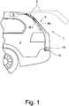
  • 1 den Heckbereich eines Kraftfahrzeugs mit einer vorschlagsgemäßen Antriebsanordnung und
  • 2 die Antriebsanordnung gemäß1 in einer ganz schematischen Darstellung.
In the following the invention will be explained with reference to only one embodiment illustrative drawing. In the drawing shows
  • 1 the rear area of a motor vehicle with a proposed drive arrangement and
  • 2 the drive assembly according to 1 in a very schematic representation.

Die in der Zeichnung dargestellte Antriebsanordnung1 ist einer Klappe2 eines Kraftfahrzeugs3 zugeordnet. Auf die weite Auslegung des Begriffs „Klappe“ gemäß dem einleitenden Teil der Beschreibung darf verwiesen werden. Vorliegend handelt es sich bei der Klappe2 um eine Heckklappe. Alle eine Heckklappe betreffenden Ausführungen gelten für alle anderen Arten von Klappen entsprechend.The drive arrangement shown in thedrawing 1 is aflap 2 of amotor vehicle 3 assigned. Reference may be made to the broad interpretation of the term "flap" according to the introductory part of the description. In the present case, it is theflap 2 around a tailgate. All tailgate versions apply to all other types of flaps.

Die vorschlagsgemäße Antriebsanordnung1 dient der motorischen Verstellung der Klappe2 zwischen einer in1 in durchgezogener Linie dargestellten Schließstellung und einer in1 in gestrichelter Linie dargestellten Offenstellung. Hierfür weist die Antriebsanordnung1 zwei Spindelantriebe4a,4b auf, die im montierten Zustand antriebstechnisch mit der Klappe2 einerseits und mit der Kraftfahrzeugkarosserie andererseits gekoppelt sind. Die beiden Spindelantriebe4a,4b sind jeweils mit einem AntriebsmotorM1,M2 ausgestattet, die in ans sich üblicher Weise ein Spindel-Spindelmutter-Getriebe antreiben.The proposeddrive arrangement 1 serves the motorized adjustment of theflap 2 between an in 1 shown in a solid line closed position and a in 1 in the dashed line shown open position. For this purpose, thedrive assembly 1 twospindle drives 4a . 4b in the assembled state, drive-technically with theflap 2 on the one hand and with the motor vehicle body on the other hand are coupled. The two spindle drives 4a . 4b are each with a drive motor M1 . M2 equipped, which drive in a conventional manner, a spindle-spindle nut transmission.

Bei dem dargestellten und insoweit bevorzugten Ausführungsbeispiel sind die beiden Spindelantriebe4a,4b an zwei gegenüberliegenden Seiten einer Klappenöffnung5, die durch die Klappe2 verschließbar ist, angeordnet. Dabei ist die Anordnung der Spindelantriebe4a,4b so getroffen, dass eine Verstellung der Klappe2 abgesehen von mechanischen Toleranzen mit weitgehend identischen Verstellbewegungen der beiden Spindelantriebe4a,4b einhergeht.In the illustrated and insofar preferred embodiment, the two spindle drives 4a . 4b on two opposite sides of a flap opening 5 that through theflap 2 is closable, arranged. Here is the arrangement of thespindle drives 4a . 4b so hit that an adjustment of theflap 2 apart from mechanical tolerances with largely identical adjustment movements of the twospindle drives 4a . 4b accompanied.

2 zeigt den grundsätzlichen Aufbau der vorschlagsgemäßen Antriebsanordnung1. Hier dargestellt ist insbesondere eine Antriebssteuerung6 zur Ansteuerung der beiden Spindelantriebe4a,4b. Die Antriebssteuerung6 weist eine Bewegungssteuerung7 auf, die über einen Datenbus8 mit einer übergeordneten Fahrzeugsteuerung kommuniziert. 2 shows the basic structure of the proposeddrive assembly 1 , Shown here is in particular adrive control 6 for controlling the twospindle drives 4a . 4b , Thedrive control 6 has amotion control 7 on that over a data bus 8th communicates with a parent vehicle controller.

Die Bewegungssteuerung7 sorgt für einen vorbestimmten Bewegungsablauf beim motorischen Öffnen und Schließen der Klappe2. Der Bewegungssteuerung7 nachgeschaltet ist ein Regler9, der von der Bewegungssteuerung7 zumindest mit Sollwerten für Verstellposition und/oder Verstellgeschwindigkeit und/oder Verstellbeschleunigung versorgt wird.Themotion control 7 ensures a predetermined movement during motorized opening and closing of theflap 2 , Of themotion control 7 Downstream is aregulator 9 that of themotion control 7 is supplied at least with set values for adjustment position and / or adjustment speed and / or Verstellbeschleunigung.

Dem Regler9 wiederum nachgeschaltet sind Treiber10a,10b, die basierend auf den Stellsignalen des Reglers9 die elektrische Antriebsleistung an die beiden Spindelantriebe4a,4b abgeben. Dieser grundsätzliche Aufbau der Antriebssteuerung6 kann auch anders vorgesehen sein. Insbesondere kann es vorgesehen sein, dass die Bewegungssteuerung7 in einer räumlich separaten Klappensteuerung implementiert ist.Theregulator 9 turn down aredrivers 10a . 10b based on the control signals of thecontroller 9 the electrical drive power to the twospindle drives 4a . 4b submit. This basic structure of thedrive control 6 can also be provided otherwise. In particular, it may be provided that themotion control 7 is implemented in a spatially separate flap control.

Wesentlich ist nun, dass die Antriebssteuerung6 dazu eingerichtet ist, für beide Spindelantriebe4a,4b jeweils eine Verstellinformation zu schätzen und eine Synchronisierung der beiden Spindelantriebe4a,4b basierend auf der jeweils geschätzten Verstellinformation miteinander zu synchronisieren.It is essential now that thedrive control 6 is set up for both spindle drives 4a . 4b each estimate an adjustment and a synchronization of the twospindle drives 4a . 4b synchronize with each other based on the respectively estimated adjustment information.

Für das vorschlagsgemäße Schätzen der Verstellinformation ist in der Antriebssteuerung6 für beide Spindelantriebe4a,4b jeweils ein Zustandsmodell11a,11b abgelegt, das den Zusammenhang zwischen mindestens einem Betriebsparameter des betreffenden Spindelantriebs4a,4b und einer Verstellinformation des betreffenden Spindelantriebs4a,4b repräsentiert.For the proposal estimating the adjustment information is in thedrive control 6 for both spindle drives 4a . 4b each astate model 11a . 11b filed, the relationship between at least one operating parameter of therespective spindle drive 4a . 4b and an adjustment of therespective spindle drive 4a . 4b represents.

Bei dem Betriebsparameter handelt es sich vorzugsweise um den Motorstrom und/oder um die Motorspannung des AntriebsmotorsM1,M2 des betreffenden Spindelantriebs4a,4b. Bei der Verstellinformation kann es sich um einen Verstellweg, insbesondere um die Auslängung, des Spindelantriebs4a,4b handeln. Der Begriff „Auslängung“ steht hier für die Längenänderung des Spindelantriebs4a,4b entlang der Längserstreckung des Spindelantriebs4a,4b. Alternativ handelt es sich bei der Verstellinformation um eine Motordrehzahl o. dgl. des AntriebsmotorsM1,M2 des Spindelantriebs4a,4b.The operating parameter is preferably the motor current and / or the motor voltage of the drive motor M1 . M2 of therelevant spindle drive 4a . 4b , The adjustment information can be an adjustment path, in particular the extension, of thespindle drive 4a . 4b act. The term "Auslängung" stands here for the change in length of thespindle drive 4a . 4b along the longitudinal extent of thespindle drive 4a . 4b , Alternatively, the adjustment information is an engine speed or the like of the drive motor M1 . M2 of thespindle drive 4a . 4b ,

Ganz allgemein ermöglicht das Zustandsmodell, von dem Betriebsparameter auf die Verstellinformation zu schließen. Ein Beispiel hierfür ist die Ermittlung der Stellung der Motorwelle des AntriebsmotorsM1,M2 aus der Messung des Motorstroms. Speziell bei Gleichstrommotoren ergeben sich im Motorstrom durch die Kommutierungsvorgänge impulsartige Verläufe (Stromripple), die Aufschluss auf eine vorbekannte Verstellung der Motorwelle geben können. Der genaue Zusammenhang zwischen dem Verstellweg der Motorwelle und gemessenem Motorstrom ist in dem vorschlagsgemäßen Zustandsmodell11a,11 b abgebildet.In general, the state model makes it possible to deduce the adjustment information from the operating parameter. An example of this is the determination of the position of the motor shaft of the drive motor M1 . M2 from the measurement of the motor current. Especially in DC motors arise in the motor current through the commutation pulse-like courses (current ripple), which can provide information on a previously known adjustment of the motor shaft. The exact relationship between the displacement of the motor shaft and measured motor current is in the proposedstate model 11a . 11 b shown.

Als Basis für das vorschlagsgemäße Schätzen der Verstellinformation ist es vorgesehen, dass die Antriebssteuerung6 fortlaufend mittels mindestens einer Messanordnung12a,12b für beide Spindelantriebe4a,4b jeweils mindestens einen Betriebsparameter misst. Hier und vorzugsweise sind zwei Messanordnungen12a,12b vorgesehen, die jeweils einem der beiden Spindelantriebe4a,4b zugeordnet sind.As a basis for the proposed estimation of the adjustment information, it is provided that thedrive control 6 continuously by means of at least one measuringarrangement 12a . 12b for both spindle drives 4a . 4b each measures at least one operating parameter. Here and preferably are two measuringarrangements 12a . 12b provided, each one of the twospindle drives 4a . 4b assigned.

Die Antriebssteuerung6 weist für beide Spindelantriebe4a,4b jeweils eine Schätzeinrichtung13a,13b auf, die fortlaufend aus einer Folge gemessener Betriebsparameter und aus dem Zustandsmodell11a,11b basierend auf einer Schätzvorschrift14a,14b die jeweilige Verstellinformation schätzt. Hinsichtlich der Einzelheiten des Schätzens einer Verstellinformation eines Antriebs basierend auf gemessenen Betriebsparametern, insbesondere auf einem Motorstrom oder einer Motorspannung, darf auf den vorbekannten Stand der Technik verwiesen werden.Thedrive control 6 points for both spindle drives 4a . 4b each anestimating device 13a . 13b consecutively from a series of measured operating parameters and from thestate model 11a . 11b based on anestimation 14a . 14b estimates the respective adjustment information. With regard to the details of the estimation of an adjustment information of a drive based on measured operating parameters, in particular on a motor current or a motor voltage, reference may be made to the prior art.

Bemerkenswert bei der vorschlagsgemäßen Lösung ist die Tatsache, dass die Antriebsanordnung1 die beiden Spindelantriebe4a,4b basierend auf der jeweils geschätzten Verstellinformation im Hinblick auf ein Synchronisierungskriterium miteinander synchronisiert. Die Synchronisierung der beiden Spindelantriebe4a,4b miteinander ist in erster Linie erforderlich, um ein Verspannen der beiden Spindelantriebe4a,4b, die beide mit der starren Klappe2 gekoppelt sind, zu vermeiden. Ein solches Verspannen kann grundsätzlich zu einem Verbiegen der Klappe2 führen, was optisch wenig ansprechend ist und sogar zu einer Zerstörung von Komponenten der Antriebsanordnung1 und/oder der Klappe2 führen kann. Für die Synchronisierung der beiden Spindelantriebe4a,4b miteinander können unterschiedliche Synchronisierungskriterien zur Anwendung kommen. Eine Variante für ein Synchronisierungskriterium ist die Bereitstellung einer identischen Verstellgeschwindigkeit für die beiden Spindelantriebe4a,4b. Alternativ kann das Synchronisierungskriterium auf einen identischen Verstellweg, insbesondere auf eine identische Auslängung, der beiden Spindelantriebe4a,4b gerichtet sein. Weiter alternativ kann es vorteilhaft sein, das Synchronisierungskriterium darauf zu richten, dass beide Spindelantriebe eine identische elektrische Leistung aufnehmen.Noteworthy in the proposed solution is the fact that thedrive assembly 1 the twospindle drives 4a . 4b synchronized with each other based on the respective estimated adjustment information with regard to a synchronization criterion. The synchronization of the twospindle drives 4a . 4b with each other is required in the first place, a distortion of the twospindle drives 4a . 4b both with therigid door 2 are coupled to avoid. Such distortion can in principle lead to bending of theflap 2 lead, which is visually unappealing and even to destruction of components of thedrive assembly 1 and / or theflap 2 can lead. For the synchronization of the twospindle drives 4a . 4b different synchronization criteria can be used with each other. A variant for a synchronization criterion is the provision of an identical adjustment speed for the twospindle drives 4a . 4b , Alternatively, the synchronization criterion to an identical adjustment, in particular to an identical Auslängung, the twospindle drives 4a . 4b be directed. Further alternatively, it may be advantageous to set the synchronization criterion that both spindle drives receive an identical electrical power.

Bei der in2 dargestellten Antriebsanordnung1 übernimmt der Regler9 selbst die Synchronisierung nach dem vorbestimmten Synchronisierungskriterium. Grundsätzlich kann es auch vorgesehen sein, dass dem Regler eine Synchronisierungseinheit nachgeschaltet ist.At the in 2 illustrateddrive assembly 1 the controller takes over 9 even the synchronization according to the predetermined synchronization criterion. In principle, it can also be provided that the controller is followed by a synchronization unit.

Die Schätzvorschrift14a,14b und/oder das Zustandsmodell11a,11b, kann bzw. können für beide Spindelantriebe4a,4b unterschiedlich parametriert sein. Es wurde weiter oben darauf hingewiesen, dass hierdurch auf geringfügige Unterschiede zwischen den beiden Spindelantrieben4a,4b, die herstellungsbedingt oder verschleißbedingt vorhanden sein können, auf besonders einfache Weise reagiert werden kann.Theestimation 14a . 14b and / or thestate model 11a . 11b , can or can for both spindle drives 4a . 4b be parameterized differently. It has been pointed out above that thereby to slight differences between the twospindle drives 4a . 4b , which may be present due to manufacturing or wear, can be responded in a particularly simple manner.

In besonders bevorzugter Ausgestaltung besteht die Schätzvorschrift darin, dass bei einer vorgegebenen Varianz des gemessenen Betriebsparameters die geschätzte Verstellinformation mit einer Mindest-Grenzwahrscheinlichkeit der tatsächlichen Verstellinformation entspricht.In a particularly preferred embodiment, the estimation provision consists in that, given a predetermined variance of the measured operating parameter, the estimated adjustment information corresponds to the actual adjustment information with a minimum limit probability.

Eine besonders robuste Vorgehensweise bei der Schätzung der Verstellinfomation besteht darin, dass für mindestens einen der Spindelantriebe4a,4b die Schätzeinrichtung13a,13b nach Art eines Kalman-Filters arbeitet. Das Kalman-Filter schätzt aus einer Folge gemessener Betriebsparameter und aus dem Zustandsmodell11a,11b basierend auf einer Schätzvorschrift14a,14b die Verstellinformation des betreffenden Spindelantriebs4a,4b. Zu Einzelheiten der Arbeitsweise eines Kalman-Filters darf auf den vorbekannten Stand der Technik verwiesen werden.A particularly robust approach in estimating the Verstellinfomation is that for at least one of the spindle drives 4a . 4b theestimator 13a . 13b works like a Kalman filter. The Kalman filter estimates from a sequence of measured operating parameters and from thestate model 11a . 11b based on anestimation 14a . 14b the adjustment information of therespective spindle drive 4a . 4b , For details of the operation of a Kalman filter reference may be made to the prior art.

Grundsätzlich kann es vorgesehen sein, dass eine Referenz-Messanordnung15 vorgesehen ist, mit der die Verstellinformation mindestens eines der Spindelantriebe4a,4b, vorzugsweise genau eines der Spindelantriebe4a,4b, messbar ist. Mit einer solchen Messung lässt sich die vorschlagsgemäße Schätzung der Verstellinformation auf die tatsächlichen Gegebenheiten anpassen. Im Einzelnen wird hierzu vorgeschlagen, dass die Antriebssteuerung6 basierend auf der geschätzten Verstellinformation und der gemessenen Verstellinformation das Zustandsmodell11a ,11b und/oder die Schätzvorschrift14a,14b zu dem jeweiligen Spindelantrieb4a,4b derart verändert, dass der Unterschied zwischen der geschätzten Verstellinformation und der gemessenen Verstellinformation minimiert wird. Es handelt sich hier um ein einfach zu lösendes Optimierungsproblem, bei dem das Zustandsmodell und/oder die Schätzvorschrift daraufhin optimiert wird bzw. werden, dass die geschätzte Verstellinformation der gemessenen Verstellinformation möglichst nahe kommt.In principle, it can be provided that areference measuring arrangement 15 is provided with the adjusting information of at least one of the spindle drives 4a . 4b , Preferably exactly one of the spindle drives 4a . 4b , is measurable. With such a measurement, the proposed estimate of the adjustment information can be adapted to the actual circumstances. In detail, it is proposed that thedrive control 6 based on the estimated adjustment information and the measured adjustment information, thestate model 11a . 11b and / or theestimation 14a . 14b to therespective spindle drive 4a . 4b changed so that the difference between the estimated Verstellinformation and the measured Verstellinformation is minimized. This is an easy-to-solve optimization problem in which the state model and / or the estimation rule is or will be optimized in such a way that the estimated adjustment information comes as close as possible to the measured adjustment information.

Die Referenz-Messanordnung kann grundsätzlich einen Wegsensor, einen Gescchwindigkeitssensor o. dgl. aufweisen. Hier und vorzugsweise ist es jedoch so, dass die Referenz-Messanordnung15 lediglich überprüft, ob die Klappe2 ihre vollständig geschlossene Stellung einnimmt. Dies bedeutet, dass beim Ansprechen der Referenz-Messanordnung15 die geschätzte Verstellinformation genau dem vollständig geschlossenen Zustand der Klappe2 entsprechen muss. Sofern sich hier eine übermäßige Abweichung ergibt, muss eine Anpassung des Zustandsmodells11a,11b und/oder der Schätzvorschrift14a,14b vorgenommen werden.The reference measuring arrangement can basically have a displacement sensor, a speed sensor or the like. Here and preferably, however, it is the case that thereference measuring arrangement 15 just checked if theflap 2 their completely closed position occupies. This means that when addressing thereference measuring device 15 the estimated adjustment information exactly the fully closed state of theflap 2 must correspond. If this results in an excessive deviation, an adaptation of thestate model 11a . 11b and / or theestimation 14a . 14b be made.

Die Referenz-Messanordnung15 ist hier und vorzugsweise Bestandteil eines Kraftfahrzeugschlosses16, das der Klappe2 zugeordnet ist. Es handelt sich hier um einen sogenannten Ajar-Sensor, der das Erreichen der Hauptschließstellung des Kraftfahrzeugschlosses16 erfasst. Die vorliegende Doppelnutzung des Ajar-Schalters des Kraftfahrzeugschlosses16 führt vorliegend zu einer besonders kostengünstigen und insgesamt kompakten Anordnung.Thereference measuring arrangement 15 is here and preferably part of amotor vehicle lock 16 That's theflap 2 assigned. This is a so-called Ajar sensor, the achievement of the main closed position of themotor vehicle lock 16 detected. The present double use of the Ajar switch of themotor vehicle lock 16 leads in the present case to a particularly cost-effective and compact overall arrangement.

Die vorschlagsgemäße Anordnung kann nicht nur für das Schätzen der Verstellinformation des bestreffenden Spindelantriebs4a,4b, sondern auch für das Schätzen eines Lastmoments an dem AntriebsmotorM1,M2 des betreffenden Spindelantriebs4a,4b genutzt werden. In diesem Rahmen ist es vorzugsweise vorgesehen, dass die Antriebssteuerung6 fortlaufend aus einer Folge gemessener Betriebsparameter und aus dem Zustandsmodell11a,11b basierend auf einer Schätzvorschrift14a,14b das Lastmoment an dem AntriebsmotorM1,M2 mindestens eines der Spindelantriebe4a,4b schätzt. Hierfür sind das Zustandsmodell11a,11b sowie die Schätzvorschrift14a,14b entsprechend anzupassen.The proposed arrangement can not only for estimating the Verstellinformation theappropriate spindle drive 4a . 4b but also for estimating a load torque on the drive motor M1 . M2 of therelevant spindle drive 4a . 4b be used. In this context, it is preferably provided that thedrive control 6 continuously from a sequence of measured operating parameters and from thestate model 11a . 11b based on anestimation 14a . 14b the load torque on the drive motor M1 . M2 at least one of the spindle drives 4a . 4b underestimated. For this the state model is 11a . 11b and theestimation 14a . 14b adjust accordingly.

Das obige Schätzen des Lastmoments ist insoweit vorteilhaft, als das geschätzte Lastmoment für die Erfassung eines Einklemmfalls genutzt werden kann. Hierbei ist es vorzugsweise vorgesehen, dass die Antriebssteuerung6 eine Einklemmroutine auslöst, wenn das geschätzte Lastmoment ein vorbestimmtes Grenz-Lastmoment übersteigt. Im Rahmen der Einklemmroutine kann es vorgesehen sein, dass beide Spindelantriebe4a,4b zunächst gestoppt und anschließend reversiert werden. Alternativ oder zusätzlich kann eine akustische, optische oder haptische Warnmeldung abgegeben werden. Andere Maßnahmen im Rahmen der Einklemmroutine sind denkbar.The above estimation of the load torque is advantageous insofar as the estimated load torque can be used for the detection of a trapping case. In this case, it is preferably provided that the drive control 6 a Einklemmroutine triggers when the estimated load torque exceeds a predetermined limit load torque. As part of the Einklemmroutine it can be provided that both spindle drives 4a . 4b first stopped and then reversed. Alternatively or additionally, an acoustic, optical or haptic warning message can be issued. Other measures within the Einklemmroutine are conceivable.

Ganz allgemein darf noch darauf hingewiesen werden, dass das vorschlagsgemäße Schätzen der Verstellinformation eines Spindelantriebs für eine Antriebsanordnung Anwendung finden kann, bei der nur dieser eine Spindelantrieb vorgesehen ist. Regelmäßig ist es dabei vorgesehen, dass zusätzlich zu dem motorischen Spindelantrieb ein passives Federelement, insbesondere ein Gasdruckdämpfer, an der Klappe angreift. Der aktive, motorische Spindelantrieb und das passive Federelement können an gegenüberliegenden Seiten der zugeordneten Klappenöffnung angreifen.Quite generally, it should also be pointed out that the proposed estimation of the adjustment information of a spindle drive can be used for a drive arrangement in which only this one spindle drive is provided. It is regularly provided that, in addition to the motor spindle drive, a passive spring element, in particular a gas pressure damper, acts on the flap. The active, motorized spindle drive and the passive spring element can engage on opposite sides of the associated flap opening.

ZITATE ENTHALTEN IN DER BESCHREIBUNG QUOTES INCLUDE IN THE DESCRIPTION

Diese Liste der vom Anmelder aufgeführten Dokumente wurde automatisiert erzeugt und ist ausschließlich zur besseren Information des Lesers aufgenommen. Die Liste ist nicht Bestandteil der deutschen Patent- bzw. Gebrauchsmusteranmeldung. Das DPMA übernimmt keinerlei Haftung für etwaige Fehler oder Auslassungen.This list of the documents listed by the applicant has been generated automatically and is included solely for the better information of the reader. The list is not part of the German patent or utility model application. The DPMA assumes no liability for any errors or omissions.

Zitierte PatentliteraturCited patent literature

  • DE 102007043372 A1 [0004]DE 102007043372 A1 [0004]

Claims (10)

Translated fromGerman
Antriebsanordnung für eine Klappe (2) eines Kraftfahrzeugs (3), wobei die Antriebsanordnung (1) zwei Spindelantriebe (4a, 4b) mit jeweils einem Antriebsmotor (M1, M2) und eine Antriebssteuerung (6) zur Ansteuerung der Spindelantriebe (4a, 4b) aufweist, wobei die Spindelantriebe (4a, 4b) im montierten Zustand antriebstechnisch mit der Klappe (2) gekoppelt sind,dadurch gekennzeichnet,dass in der Antriebssteuerung (6) für beide Spindelantriebe (4a, 4b) jeweils ein Zustandsmodell (11a, 11b) abgelegt ist, das den Zusammenhang zwischen mindestens einem Betriebsparameter des betreffenden Spindelantriebs (4a, 4b), insbesondere dem Motorstrom und/oder der Motorspannung, und einer Verstellinformation, insbesondere einem Verstellweg, des betreffenden Spindelantriebs (4a, 4b) repräsentiert,dass die Antriebssteuerung (6) fortlaufend mittels mindestens einer Messanordnung (12a, 12b) für beide Spindelantriebe (4a, 4b) jeweils mindestens einen Betriebsparameter misst,dass die Antriebssteuerung (6) für beide Spindelantriebe (4a, 4b) jeweils eine Schätzeinrichtung (13a, 13b) aufweist, die fortlaufend aus einer Folge gemessener Betriebsparameter und aus dem Zustandsmodell (11a, 11b) basierend auf einer Schätzvorschrift (14a, 14b) die jeweilige Verstellinformation schätzt unddass die Antriebssteuerung (6) die beiden Spindelantriebe (4a, 4b) basierend auf der jeweils geschätzten Verstellinformation im Hinblick auf ein Synchronisierungskriterium miteinander synchronisiert.Drive arrangement for a flap (2) of a motor vehicle (3), wherein the drive arrangement (1) has two spindle drives (4a, 4b) each with a drive motor (M1, M2) and a drive control (6) for controlling the spindle drives (4a, 4b) wherein the spindle drives (4a, 4b) in the mounted state are drivingly coupled to the flap (2),characterized in that a state model (11a, 11b) is stored in the drive control (6) for both spindle drives (4a, 4b) is that the relationship between at least one operating parameter of the respective spindle drive (4a, 4b), in particular the motor current and / or the motor voltage, and an adjustment information, in particular an adjustment of the respective spindle drive (4a, 4b) represents that the drive control (6 ) continuously by means of at least one measuring arrangement (12a, 12b) for both spindle drives (4a, 4b) each measures at least one operating parameter that the drive control g (6) for both spindle drives (4a, 4b) each have an estimating device (13a, 13b) which continuously from a sequence of measured operating parameters and from the state model (11a, 11b) based on an estimation rule (14a, 14b) the respective adjustment information estimates and that the drive control (6) synchronizes the two spindle drives (4a, 4b) based on the respective estimated adjustment information with respect to a synchronization criterion with each other.Antriebsanordnung nachAnspruch 1,dadurch gekennzeichnet, dass das Synchronisierungskriterium eine identische Verstellgeschwindigkeit, ein identischer Verstellweg, insbesondere eine identische Auslängung, eine identische elektrische Leistungsaufnahme, o. dgl. der beiden Spindelantriebe (4a, 4b) ist.Drive arrangement according to Claim 1 ,characterized in that the synchronization criterion is an identical adjustment speed, an identical adjustment path, in particular an identical extension, an identical electrical power consumption, o. The like. The two spindle drives (4a, 4b).Antriebsanordnung nachAnspruch 1 oder2,dadurch gekennzeichnet, dass die Schätzvorschrift (14a, 14b) und/oder das Zustandsmodell (11a, 11b) für die beiden Spindelantriebe (4a, 4b) unterschiedlich parametriert ist bzw. sind.Drive arrangement according to Claim 1 or 2 ,characterized in that the estimation rule (14a, 14b) and / or the state model (11a, 11b) for the two spindle drives (4a, 4b) is parameterized differently or are.Antriebsanordnung nach einem der vorhergehenden Ansprüche,dadurch gekennzeichnet, dass für mindestens einen der Spindelantriebe (4a, 4b) die Schätzvorschrift (14a, 14b) darin besteht, dass bei einer vorgegebenen Varianz des gemessenen Betriebsparameters die geschätzte Verstellinformation mit einer Mindest-Grenzwahrscheinlichkeit der tatsächlichen Verstellinformation entspricht.Drive arrangement according to one of the preceding claims,characterized in that for at least one of the spindle drives (4a, 4b) the estimation rule (14a, 14b) consists in that for a given variance of the measured operating parameter, the estimated adjustment information having a minimum limit probability of the actual adjustment information equivalent.Antriebsanordnung nach einem der vorhergehenden Ansprüche,dadurch gekennzeichnet, dass für mindestens einen der Spindelantriebe (4a, 4b) die Schätzeinrichtung (13a, 13b) nach Art eines Kalman-Filters arbeitet, das fortlaufend aus einer Folge gemessener Betriebsparameter und aus dem Zustandsmodell (11a, 11b) basierend auf einer Schätzvorschrift (14a, 14b) die Verstellinformation schätzt.Drive arrangement according to one of the preceding claims,characterized in that for at least one of the spindle drives (4a, 4b) the estimating device (13a, 13b) operates in the manner of a Kalman filter, which continuously from a sequence of measured operating parameters and from the state model (11a, 11b) estimates the adjustment information based on an estimation rule (14a, 14b).Antriebsanordnung nach einem der vorhergehenden Ansprüche,dadurch gekennzeichnet, dass eine Referenz-Messanordnung (15) vorgesehen ist, mit der die Verstellinformation mindestens eines der Spindelantriebe (4a, 4b), vorzugsweise genau eines der Spindelantriebe (4a, 4b), messbar ist, dass die Antriebssteuerung (6) basierend auf der geschätzten Verstellinformation und der gemessenen Verstellinformation das Zustandsmodell (11a, 11b) und/oder die Schätzvorschrift (14a, 14b) zu dem jeweiligen Spindelantrieb (4a, 4b) derart verändert, dass der Unterschied zwischen der geschätzten Verstellinformation und der gemessenen Verstellinformation minimiert wird.Drive arrangement according to one of the preceding claims,characterized in that a reference measuring arrangement (15) is provided, with which the Verstellinformation at least one of the spindle drives (4a, 4b), preferably exactly one of the spindle drives (4a, 4b), is measurable that the drive controller (6) changes the state model (11a, 11b) and / or the estimation rule (14a, 14b) to the respective spindle drive (4a, 4b) based on the estimated adjustment information and the measured adjustment information such that the difference between the estimated adjustment information and the measured Verstellinformation is minimized.Antriebsanordnung nachAnspruch 6,dadurch gekennzeichnet, dass die Referenz-Messanordnung (15) einen Wegsensor aufweist, oder, dass die Referenz-Messanordnung (15) einen Inertialsensor aufweist.Drive arrangement according to Claim 6 ,characterized in that the reference measuring arrangement (15) comprises a displacement sensor, or in that the reference measuring arrangement (15) has an inertial sensor.Antriebsanordnung nach einem derAnsprüche 6 oder7,dadurch gekennzeichnet, dass die Referenz-Messanordnung (15) dem Spindelantrieb (4a, 4b) bzw. einem der Spindelantriebe (4a, 4b) zugeordnet ist, oder, dass die Referenz-Messanordnung (15) der Klappe (2) zugeordnet ist.Drive arrangement according to one of Claims 6 or 7 ,characterized in that the reference measuring arrangement (15) is associated with the spindle drive (4a, 4b) or one of the spindle drives (4a, 4b), or that the reference measuring arrangement (15) is associated with the flap (2).Antriebsanordnung nach einem der vorhergehenden Ansprüche,dadurch gekennzeichnet, dass die Antriebssteuerung (6) fortlaufend aus einer Folge gemessener Betriebsparameter und aus dem Zustandsmodell (11a, 11b) basierend auf einer Schätzvorschrift (14a, 14b) das Lastmoment an dem Antriebsmotor (M1, M2) mindestens eines der Spindelantriebe (4a, 4b) schätzt.Drive arrangement according to one of the preceding claims,characterized in that the drive control (6) continuously from a sequence of measured operating parameters and from the state model (11a, 11b) based on an estimation rule (14a, 14b) the load torque on the drive motor (M1, M2) at least one of the spindle drives (4a, 4b) estimates.Antriebsanordnung nachAnspruch 9,dadurch gekennzeichnet, dass die Antriebssteuerung (6) eine Einklemmroutine auslöst, wenn das geschätzte Lastmoment ein vorbestimmtes Grenz-Lastmoment übersteigt.Drive arrangement according to Claim 9 ,characterized in that the drive control (6) triggers a Einklemmroutine when the estimated load torque exceeds a predetermined limit load torque.
DE102017115024.2A2017-07-052017-07-05 Drive arrangement for a flap of a motor vehiclePendingDE102017115024A1 (en)

Priority Applications (1)

Application NumberPriority DateFiling DateTitle
DE102017115024.2ADE102017115024A1 (en)2017-07-052017-07-05 Drive arrangement for a flap of a motor vehicle

Applications Claiming Priority (1)

Application NumberPriority DateFiling DateTitle
DE102017115024.2ADE102017115024A1 (en)2017-07-052017-07-05 Drive arrangement for a flap of a motor vehicle

Publications (1)

Publication NumberPublication Date
DE102017115024A1true DE102017115024A1 (en)2019-01-10

Family

ID=64666326

Family Applications (1)

Application NumberTitlePriority DateFiling Date
DE102017115024.2APendingDE102017115024A1 (en)2017-07-052017-07-05 Drive arrangement for a flap of a motor vehicle

Country Status (1)

CountryLink
DE (1)DE102017115024A1 (en)

Cited By (3)

* Cited by examiner, † Cited by third party
Publication numberPriority datePublication dateAssigneeTitle
WO2020165036A1 (en)*2019-02-112020-08-20Brose Fahrzeugteile Se & Co. Kommanditgesellschaft, BambergControl system
WO2021023766A1 (en)*2019-08-052021-02-11Brose Fahrzeugteile Se & Co. Kommanditgesellschaft, BambergDrive device for adjusting a vehicle assembly
US12345085B2 (en)2019-08-052025-07-01Brose Fahrzeugteile Se & Co. Kommanditgesellschaft, BambergDrive device for adjusting a vehicle assembly

Citations (3)

* Cited by examiner, † Cited by third party
Publication numberPriority datePublication dateAssigneeTitle
DE102007003601A1 (en)*2006-01-182007-07-26Küster Automotive Control Systems GmbHVehicle body part adjusting device e.g. spoiler, has transmission device with translationally movable mechanically flexible transmission elements for transferring drive movement of electric motor and hence adjusting movement of body parts
DE102007043372A1 (en)2006-09-212008-04-03BROSE SCHLIEßSYSTEME GMBH & CO. KGDrive arrangement for adjustable functional element in motor vehicle, has multiple partially electrical drive components arranged behind one another along axis, where drive arrangement has multipart drive housing
DE102008008743B4 (en)*2008-02-122011-04-14Stabilus Gmbh driving means

Patent Citations (3)

* Cited by examiner, † Cited by third party
Publication numberPriority datePublication dateAssigneeTitle
DE102007003601A1 (en)*2006-01-182007-07-26Küster Automotive Control Systems GmbHVehicle body part adjusting device e.g. spoiler, has transmission device with translationally movable mechanically flexible transmission elements for transferring drive movement of electric motor and hence adjusting movement of body parts
DE102007043372A1 (en)2006-09-212008-04-03BROSE SCHLIEßSYSTEME GMBH & CO. KGDrive arrangement for adjustable functional element in motor vehicle, has multiple partially electrical drive components arranged behind one another along axis, where drive arrangement has multipart drive housing
DE102008008743B4 (en)*2008-02-122011-04-14Stabilus Gmbh driving means

Cited By (3)

* Cited by examiner, † Cited by third party
Publication numberPriority datePublication dateAssigneeTitle
WO2020165036A1 (en)*2019-02-112020-08-20Brose Fahrzeugteile Se & Co. Kommanditgesellschaft, BambergControl system
WO2021023766A1 (en)*2019-08-052021-02-11Brose Fahrzeugteile Se & Co. Kommanditgesellschaft, BambergDrive device for adjusting a vehicle assembly
US12345085B2 (en)2019-08-052025-07-01Brose Fahrzeugteile Se & Co. Kommanditgesellschaft, BambergDrive device for adjusting a vehicle assembly

Similar Documents

PublicationPublication DateTitle
EP1075723B1 (en)Closing device with a safety function
DE102007062472B4 (en) Device and method for adjusting a force of an actuator and door, in particular vehicle door, which is associated with such an actuator
DE102011112274A1 (en) control system
EP1256154B1 (en)Method of electronically monitoring and controlling a process for the adjustment of mobile parts
DE102013114883A1 (en) Control system for a motor-driven closure element arrangement of a motor vehicle
DE102012008235B4 (en) Precise positioning detection in a motor-driven vehicle part
DE102013114881A1 (en) Control system for a motor-driven closure element arrangement of a motor vehicle
DE102011014814A1 (en)Method for detecting actuating movement for sensor-controlled activation of actuator for fitting element of motor vehicle, involves determining direction of actuating movement within overlapping detection areas as valid movement direction
WO2009065701A1 (en)Method and device for correcting temperature-dependent changes in the mechanical properties of a mobile closing part of a vehicle
EP1319264B1 (en)Method for making allowance for the vehicle attitude on operating closing piece systems on motor vehicles
WO2020043773A1 (en)Method for the operation of a motorized flap arrangement of a motor vehicle
DE102015119799A1 (en) Drive arrangement for a closure element of a motor vehicle
DE102017115586A1 (en) drive arrangement
DE102014101661A1 (en) Method for controlling a closure element arrangement of a motor vehicle
DE102017115024A1 (en) Drive arrangement for a flap of a motor vehicle
DE102018108473A1 (en) Method for controlling a drive arrangement for a flap of a motor vehicle
DE102016220151B4 (en) Method and system for determining the position of a vehicle outer part
DE102019104598A1 (en) Method for controlling a drive arrangement for a flap of a motor vehicle
DE102012013067A1 (en) Method for controlling a motorized flap arrangement of a motor vehicle
DE102014013213A1 (en) Collision protection device for a vehicle door and method for operating such a collision protection device
DE102019107024A1 (en) Drive arrangement for the motorized adjustment of a closure element of a motor vehicle
DE102019103769A1 (en) Electronic tensioning device for a short-running window regulator system in a frameless door
DE102017118894A1 (en) Method for operating a damper drive
DE102016205325A1 (en) Adjusting device for an adjustable vehicle part and method for operating such
DE102018107184A1 (en) Method for controlling a motorized flap arrangement of a motor vehicle

Legal Events

DateCodeTitleDescription
R163Identified publications notified
R081Change of applicant/patentee

Owner name:BROSE FAHRZEUGTEILE SE & CO. KOMMANDITGESELLSC, DE

Free format text:FORMER OWNER: BROSE FAHRZEUGTEILE GMBH & CO. KOMMANDITGESELLSCHAFT, BAMBERG, 96052 BAMBERG, DE

R082Change of representative

Representative=s name:GOTTSCHALD PATENTANWAELTE PARTNERSCHAFT MBB, DE

R012Request for examination validly filed

[8]ページ先頭

©2009-2025 Movatter.jp