DE102017114273A1 - Extension device for a bone anchor - Google Patents
Extension device for a bone anchorDownload PDFInfo
- Publication number
- DE102017114273A1 DE102017114273A1DE102017114273.8ADE102017114273ADE102017114273A1DE 102017114273 A1DE102017114273 A1DE 102017114273A1DE 102017114273 ADE102017114273 ADE 102017114273ADE 102017114273 A1DE102017114273 A1DE 102017114273A1
- Authority
- DE
- Germany
- Prior art keywords
- bone anchor
- head
- extension device
- spring element
- shell part
- Prior art date
- Legal status (The legal status is an assumption and is not a legal conclusion. Google has not performed a legal analysis and makes no representation as to the accuracy of the status listed.)
- Pending
Links
- 210000000988bone and boneAnatomy0.000titleclaimsabstractdescription118
- 238000001356surgical procedureMethods0.000claimsabstractdescription6
- 238000002513implantationMethods0.000claimsdescription5
- 239000000463materialSubstances0.000claimsdescription5
- 238000004519manufacturing processMethods0.000claimsdescription3
- 239000000654additiveSubstances0.000claimsdescription2
- 230000000996additive effectEffects0.000claimsdescription2
- 238000003801millingMethods0.000claimsdescription2
- 230000003313weakening effectEffects0.000claimsdescription2
- 150000001875compoundsChemical class0.000claims1
- 210000002414legAnatomy0.000description9
- 210000000689upper legAnatomy0.000description4
- 230000006641stabilisationEffects0.000description2
- 238000011105stabilizationMethods0.000description2
- BUHVIAUBTBOHAG-FOYDDCNASA-N(2r,3r,4s,5r)-2-[6-[[2-(3,5-dimethoxyphenyl)-2-(2-methylphenyl)ethyl]amino]purin-9-yl]-5-(hydroxymethyl)oxolane-3,4-diolChemical compoundCOC1=CC(OC)=CC(C(CNC=2C=3N=CN(C=3N=CN=2)[C@H]2[C@@H]([C@H](O)[C@@H](CO)O2)O)C=2C(=CC=CC=2)C)=C1BUHVIAUBTBOHAG-FOYDDCNASA-N0.000description1
- 2380000101463D printingMethods0.000description1
- 206010016256fatigueDiseases0.000description1
- 239000007943implantSubstances0.000description1
- 230000014759maintenance of locationEffects0.000description1
- 229910001092metal group alloyInorganic materials0.000description1
- 238000002324minimally invasive surgeryMethods0.000description1
- 230000003716rejuvenationEffects0.000description1
- 238000010408sweepingMethods0.000description1
Images


Classifications
- A—HUMAN NECESSITIES
- A61—MEDICAL OR VETERINARY SCIENCE; HYGIENE
- A61B—DIAGNOSIS; SURGERY; IDENTIFICATION
- A61B17/00—Surgical instruments, devices or methods
- A61B17/56—Surgical instruments or methods for treatment of bones or joints; Devices specially adapted therefor
- A61B17/58—Surgical instruments or methods for treatment of bones or joints; Devices specially adapted therefor for osteosynthesis, e.g. bone plates, screws or setting implements
- A61B17/68—Internal fixation devices, including fasteners and spinal fixators, even if a part thereof projects from the skin
- A61B17/70—Spinal positioners or stabilisers, e.g. stabilisers comprising fluid filler in an implant
- A61B17/7074—Tools specially adapted for spinal fixation operations other than for bone removal or filler handling
- A61B17/7083—Tools for guidance or insertion of tethers, rod-to-anchor connectors, rod-to-rod connectors, or longitudinal elements
- A61B17/7085—Tools for guidance or insertion of tethers, rod-to-anchor connectors, rod-to-rod connectors, or longitudinal elements for insertion of a longitudinal element down one or more hollow screw or hook extensions, i.e. at least a part of the element within an extension has a component of movement parallel to the extension's axis
- A—HUMAN NECESSITIES
- A61—MEDICAL OR VETERINARY SCIENCE; HYGIENE
- A61B—DIAGNOSIS; SURGERY; IDENTIFICATION
- A61B17/00—Surgical instruments, devices or methods
- A61B17/56—Surgical instruments or methods for treatment of bones or joints; Devices specially adapted therefor
- A61B17/58—Surgical instruments or methods for treatment of bones or joints; Devices specially adapted therefor for osteosynthesis, e.g. bone plates, screws or setting implements
- A61B17/68—Internal fixation devices, including fasteners and spinal fixators, even if a part thereof projects from the skin
- A61B17/70—Spinal positioners or stabilisers, e.g. stabilisers comprising fluid filler in an implant
- A61B17/7001—Screws or hooks combined with longitudinal elements which do not contact vertebrae
- A61B17/7032—Screws or hooks with U-shaped head or back through which longitudinal rods pass
- A—HUMAN NECESSITIES
- A61—MEDICAL OR VETERINARY SCIENCE; HYGIENE
- A61B—DIAGNOSIS; SURGERY; IDENTIFICATION
- A61B90/00—Instruments, implements or accessories specially adapted for surgery or diagnosis and not covered by any of the groups A61B1/00 - A61B50/00, e.g. for luxation treatment or for protecting wound edges
- A61B90/03—Automatic limiting or abutting means, e.g. for safety
- A61B2090/037—Automatic limiting or abutting means, e.g. for safety with a frangible part, e.g. by reduced diameter
Landscapes
- Health & Medical Sciences (AREA)
- Orthopedic Medicine & Surgery (AREA)
- Neurology (AREA)
- Life Sciences & Earth Sciences (AREA)
- Surgery (AREA)
- Heart & Thoracic Surgery (AREA)
- Engineering & Computer Science (AREA)
- Biomedical Technology (AREA)
- Nuclear Medicine, Radiotherapy & Molecular Imaging (AREA)
- Medical Informatics (AREA)
- Molecular Biology (AREA)
- Animal Behavior & Ethology (AREA)
- General Health & Medical Sciences (AREA)
- Public Health (AREA)
- Veterinary Medicine (AREA)
- Surgical Instruments (AREA)
- Prostheses (AREA)
Abstract
Translated fromGerman
Description
Translated fromGermanDie Erfindung betrifft eine Verlängerungsvorrichtung für einen Knochenanker, insbesondere für eine Knochenschraube, insbesondere für eine Pedikelschraube, insbesondere in der minimalinvasiven Wirbelsäulenchirurgie, mit einer axialen Längsrichtung, einer hierzu konzentrischen Umfangsrichtung und einer radialen Richtung, wobei die Verlängerungsvorrichtung in der axialen Längsrichtung erstreckt ist und mittels eines radialen Vorsprungs einen hintergreifbaren Bereich am Kopf des Knochenankers in der Längsrichtung und zudem in der radialen Richtung hintergreift und in entgegengesetzter Richtung gegen den Kopf des Knochenankers abstützbar ist, so dass die Verlängerungsvorrichtung hierdurch am Kopf des Knochenankers lösbar, jedoch in der Längsrichtung starr und zudem drehfest fixierbar ist.The invention relates to an extension device for a bone anchor, in particular for a bone screw, in particular for a pedicle screw, in particular in minimally invasive spinal surgery, with an axial longitudinal direction, a circumferential direction concentric thereto and a radial direction, wherein the extension device is extended in the axial longitudinal direction and means a radial projection engages behind an engageable region on the head of the bone anchor in the longitudinal direction and also in the radial direction and in the opposite direction against the head of the bone anchor is supportable, so that the extension device thereby releasably at the head of the bone anchor, but rigid in the longitudinal direction and also is rotatably fixed.
Verlängerungsvorrichtungen der vorstehend genannten Art finden bevorzugt bei minimalinvasiven Eingriffen, insbesondere zur Implantation von Knochenankern Verwendung. Sie sollen während des chirurgischen Eingriffs gewissermaßen einen Arbeitskanal zu dem Knochenanker zugänglich halten, durch den der Chirurg mittels weiterer Instrumente den Knochenanker befestigen und gegebenenfalls weitere Implantatteile zuführen und befestigen kann und repositionierende Maßnahmen ausführen kann.Extension devices of the aforementioned type are preferably used in minimally invasive procedures, in particular for the implantation of bone anchors. During the surgical procedure, they should, so to speak, hold a working channel accessible to the bone anchor, by means of which the surgeon can fix the bone anchor by means of further instruments and optionally supply and fix further implant parts and perform repositioning measures.
Eine Verlängerungsvorrichtung mit zwei voneinander separaten Schalenteilen ist beispielsweise bekannt aus
Der vorliegenden Erfindung liegt die Aufgabe zugrunde, eine Verlängerungsvorrichtung für einen Knochenanker zu schaffen, die auf einfache Weise vor oder nach der Implantation des Knochenankers am Kopf des Knochenankers lösbar festlegbar ist, wobei ein unbeabsichtigtes Ablösen der Verlängerungsvorrichtung sicher vermieden werden können soll.The present invention has for its object to provide an extension device for a bone anchor, which is easily releasably secured before or after implantation of the bone anchor at the head of the bone anchor, with an unintentional detachment of the extension device should be safely avoided.
Diese Aufgabe wird bei einer Verlängerungsvorrichtung der genannten Art erfindungsgemäß dadurch gelöst, dass die Verlängerungsvorrichtung wenigstens ein und vorzugsweise zwei voneinander separate, und in der Längsrichtung erstreckte Schalenteile umfasst, von denen jedes einen radialen Vorsprung zum Hintergreifen des hintergreifbaren Bereichs am Kopf des Knochenankers umfasst, dass das Schalenteil überwiegend im Wesentlichen starr ausgebildet ist, jedoch einen ersten deformierbaren Bereich aufweist, dass der erste deformierbare Bereich ein in der axialen Längsrichtung erstrecktes und quer hierzu, insbesondere im Wesentlichen radial nach außen, auslenkbares Federelement bildet, dass das Federelement proximal zu dem radialen Vorsprung zum Hintergreifen des hintergreifbaren Bereichs am Kopf des Knochenankers einen nach radial innen vorstehenden Abstützbereich aufweist, mittels dessen das Federelement und damit das Schalenteil in axialer Längsrichtung gegen den Kopf des Knochenankers abstützbar ist, so dass die Verlängerungsvorrichtung hierdurch am Kopf des Knochenankers lösbar fixierbar ist, wenn der Vorsprung den hintergreifbaren Bereich am Kopf des Knochenankers hintergreift, und dass das Federelement zum Lösen der Verlängerungsvorrichtung radial nach außen auslenkbar ist, so dass sein Abstützbereich vom Kopf des Knochenankers frei kommt und das Schalenteil gegenüber dem Kopf des Knochenankers aus dem hintergreifbaren Bereich am Kopf des Knochenankers in der Längsrichtung distal herausbewegt werden kann.This object is achieved in an extension device of the type mentioned according to the invention that the extension device comprises at least one and preferably two separate, and in the longitudinal direction extending shell parts, each of which comprises a radial projection for engaging behind the reach behind the head of the bone anchor that the shell part is predominantly substantially rigid, but has a first deformable region, that the first deformable region forms a spring element which extends in the axial longitudinal direction and can be deflected transversely thereto, in particular substantially radially outwards, such that the spring element is proximal to the radial projection for engaging behind the graspable region at the head of the bone anchor has a radially inwardly projecting support region, by means of which the spring element and thus the shell part in the axial longitudinal direction against the head of Knochenan Kers is supportable, so that the extension device is thereby releasably fixed to the head of the bone anchor when the projection engages behind the gripping behind the head of the bone anchor, and that the spring element for releasing the extension device is deflected radially outwards, so that its support portion of the head of Bone anchor comes free and the shell part relative to the head of the bone anchor from the behind reachable area on the head of the bone anchor can be moved distally in the longitudinal direction.
Obschon vorzugsweise zwei Schalenteile zum Einsatz gelangen, damit diese beiden Schalenteile einen Arbeitskanal bilden können, ist es grundsätzlich denkbar, in bestimmten Situationen mit nur einem Schalenteil zu arbeiten. Werden zwei Schalenteile eingesetzt, so erweist es sich als vorteilhaft, wenn sie beide entsprechend der Erfindung und vorzugsweise identisch bzw. einander entsprechend ausgebildet sind.Although preferably two shell parts are used so that these two shell parts can form a working channel, it is generally conceivable to work with only one shell part in certain situations. If two shell parts are used, it proves to be advantageous if they are both formed according to the invention and preferably identical or mutually corresponding.
Die erfindungsgemäße Verlängerungsvorrichtung bzw. deren jeweiliges Schalenteil ist am Kopf der Knochenschraube fixierbar, ohne dass zum unmittelbaren Halten eine Kraft erforderlich ist. Die Fixierung oder Halteverbindung ist vielmehr über einen Formschluss bezüglich aller Freiheitsgrade realisiert. Dadurch, dass der erste deformierbare Bereich bzw. das von ihm gebildete Federelement quer zur Längsrichtung auslenkbar ist, jedoch einen nach radial innen vorstehenden Abstützbereich aufweist, mittels dessen eine Abstützung in axialer Längsrichtung gegen den Kopf des Knochenankers in der Halteverbindung ausgeübt ist, ist das Schalenteil in axialer Richtung unverlierbar am Kopf des Knochenankers fixiert, da durch die axiale Abstützung verhindert ist, dass sich der radiale Vorsprung des Schalenteils aus dem hintergreifbaren Bereich am Kopf des Knochenankers in distaler Richtung löst. Durch den Abstützbereich kann zugleich eine formschlüssige Halterung in Umfangsrichtung erzielt werden. Es ist aber auch denkbar, dass dies alternativ oder zusätzlich in anderer Weise realisiert ist, also z.B. durch ein weiteres Federelement oder durch seitliche nach innen eingezogene Längsrandbereiche des Schalenteils, welche an Längsflanken der Schenkel des Kopfs des Knochenankers anliegen, oder über den radialen Vorsprung des Schalenteils selbst, der in den entsprechend mit Umfangsanschlägen versehenen hintergreifbaren Bereich am Kopf des Knochenankers eingreift.The extension device according to the invention or its respective shell part can be fixed to the head of the bone screw, without a force being required for immediate holding. The fixation or holding connection is rather realized via a form fit with respect to all degrees of freedom. The fact that the first deformable region or the spring element formed by it is deflectable transversely to the longitudinal direction, but has a radially inwardly projecting support region, by means of which a support in the axial longitudinal direction is exerted against the head of the bone anchor in the holding connection, is the shell part Captively fixed in the axial direction on the head of the bone anchor, as prevented by the axial support that the radial projection of the shell part of the reach behind reachable area on the head of the bone anchor in the distal direction. By the support area can be achieved in the circumferential direction at the same time a positive retention. But it is also conceivable that this is alternatively or additionally realized in another way, so for example by a further spring element or by lateral inwardly drawn longitudinal edge portions of the shell part, which rest on longitudinal edges of the legs of the head of the bone anchor, or on the radial projection of the Shell part itself, which engages in the provided with circumferential stops behind reachable area on the head of the bone anchor.
Zum Fügen, d.h. zum Herstellen der lösbaren Halte- oder Fixierverbindung des jeweiligen Schalenteils mit dem Kopf des Knochenankers, wird nach einer Ausführungsvariante das Schalenteil am Außenumfang des Knochenankers positioniert, derart, dass der radiale Vorsprung des Schalenteils sich distal zu dem hintergreifbaren Bereich am Kopf des Knochenankers befindet. Dann wird das Schalenteil relativ zu dem Knochenanker in proximaler Richtung bewegt, bis der radiale Vorsprung in den hintergreifbaren Bereich am Kopf des Knochenankers eingreift oder einrastet und dabei auch die radiale Richtung hintergreift. In dieser Position kann das Federelement nach radial innen federnd einschwenken und damit der Abstützbereich des Federelements in eine axiale Abstützung am Kopf des Knochenankers gelangen. Somit ist das Schalenteil verliersicher am Kopf des Knochenankers gehalten. Zum Lösen dieser Halteverbindung muss das Federelement nach außen ausgelenkt werden, was den Einsatz eines hierfür speziell ausgebildeten Instruments vorzugsweise erfordert, um ein unbeabsichtigtes Lösen sicher zu verhindern.For joining, i. For producing the releasable holding or fixing connection of the respective shell part with the head of the bone anchor, according to one embodiment, the shell part is positioned on the outer circumference of the bone anchor, such that the radial projection of the shell part is located distally to the hintergreifbaren area at the head of the bone anchor. Then, the shell part is moved relative to the bone anchor in the proximal direction until the radial projection engages or snaps into the hintergreifbaren area at the head of the bone anchor and thereby engages behind the radial direction. In this position, the spring element can pivot inwardly radially inwardly and thus reach the support region of the spring element in an axial support on the head of the bone anchor. Thus, the shell part is held captive on the head of the bone anchor. To release this holding connection, the spring element must be deflected outwards, which preferably requires the use of a specially designed instrument for this, in order to reliably prevent unintentional loosening.
Nach einer Ausführungsform der Erfindung erweist es sich als vorteilhaft, wenn das Federelement einstückig mit dem Schalenteil ausgebildet ist und an seinem proximalen Ende in eine Wandung des Schalenteils übergeht. Auf diese Weise kann das Federelement und das Schalenteil aus demselben Werkstoff gefertigt werden, eine anschließende Montage des Federelements ist nicht erforderlich.According to one embodiment of the invention, it proves to be advantageous if the spring element is formed integrally with the shell part and merges at its proximal end into a wall of the shell part. In this way, the spring element and the shell part can be made of the same material, a subsequent assembly of the spring element is not required.
Weiter erweist es sich als vorteilhaft, wenn das Federelement durch einen materialfreien Schlitz in der Wandung des Schadenteils begrenzt ist und an seinem proximalen Ende einstückig in die Wandung des Schalenteils übergeht.Further, it proves to be advantageous if the spring element is limited by a material-free slot in the wall of the damaged part and merges at its proximal end in one piece into the wall of the shell part.
Weiter erweist es sich als vorteilhaft, dass der materialfreie Schlitz proximal gekrümmt ausläuft, insbesondere mit einem Krümmungsradius von 0,5 - 5 mm. Hierdurch kann die Spannung beim Auslenken des Federelements gleichmäßiger in einen größeren Bereich in der Wandung des Schalenteils verteilt werden und eine frühzeitige Ermüdung verhindert werden. Alternativ oder zusätzlich hierzu erweist es sich als vorteilhaft, wenn der materialfreie Schlitz an seinem Ende in eine gegenüber der Schlitzbreite größere Öffnung ausmündet. Auch hierdurch können durch die Auslenkung des Federelements eingeleitete Kräfte gleichmäßiger verteilt werden.Furthermore, it proves to be advantageous that the material-free slot expires proximally curved, in particular with a radius of curvature of 0.5 - 5 mm. In this way, the tension when deflecting the spring element can be distributed more uniformly in a larger area in the wall of the shell part and early fatigue can be prevented. Alternatively or additionally, it proves to be advantageous if the material-free slot opens at its end in a relation to the slot width larger opening. This also allows forces introduced by the deflection of the spring element to be distributed more uniformly.
Bei der Ausbildung des Federelements kann es sich als vorteilhaft erweisen, dass Federelement in einem Bereich seines Federarms proximal zu dem nach radial innen vorstehenden Abstützbereich eine in der axialen Längsrichtung in proximaler Richtung zunehmende Wanddicke aufweist. Insbesondere zusätzlich zu der vorgenannten Maßnahme kann es sich als vorteilhaft erweisen, dass das Federelement in einem Bereich seines Federarms proximal zu dem nach radial innen vorstehenden Abstützbereich eine in der axialen Längsrichtung in proximaler Richtung zunehmende Breite in der Umfangsrichtung aufweist. Weiter kann es sich als vorteilhaft erweisen, wenn das Federelement dadurch einstückig mit dem Schalenteil ausgebildet ist, dass es aus einer zuvor durchgehenden Wandung des Schalenteils durch einen Schnitt, Fräsen oder sonstige Materialabnahme freigeformt wurde. Alternativ hierzu sind additive Fertigungsverfahren, insbesondere 3D-Druck, denkbar, im Zuge derer das Schalenteil zusammen mit dem ersten deformierbaren Bereich bzw. mit dem Federelement hergestellt werden kann. Des Weiteren ist eine Kombination dieser Fertigungsverfahren denkbar. Als Werkstoffe sind metallische Legierungen sowie röntgendurchlässige Materialien denkbar.In the design of the spring element, it may prove to be advantageous that spring element in a region of its spring arm proximal to the radially inwardly projecting support region has an increasing in the axial longitudinal direction in the proximal direction wall thickness. In particular, in addition to the aforementioned measure, it may prove to be advantageous that the spring element in a region of its spring arm proximal to the radially inwardly projecting support region in the axial longitudinal direction in the proximal direction increasing width in the circumferential direction. Further, it may prove to be advantageous if the spring element is formed integrally with the shell part, that it has been freed from a previously continuous wall of the shell part by a cut, milling or other material removal. Alternatively, additive manufacturing methods, in particular 3D printing, are conceivable in the course of which the shell part can be produced together with the first deformable region or with the spring element. Furthermore, a combination of these manufacturing methods is conceivable. As materials metallic alloys and radiolucent materials are conceivable.
Bei einer ganz besonders bevorzugten Ausführungsform der Erfindung wird vorgeschlagen, dass das Federelement in der Längsrichtung distal bis über den radialen Vorsprung zum Hintergreifen des hintergreifbaren Bereichs am Kopf des Knochenankers erstreckt ist und dort einen nach radial innen vorstehenden Eingriffsbereich aufweist, der in eine Eingriffsvertiefung am Kopf des Knochenankers einrastbar ist und eine zusätzliche formschlüssige Verbindung zwischen dem Schalenteil und dem Kopf des Knochenankers herstellen kann. Nach diesem Vorschlag bildet das Federelement nicht nur den axialen Abstützbereich, welcher proximal zu dem radialen Vorsprung vorgesehen ist, sondern es erstreckt sich zusätzlich weiter in distaler Richtung und weist dort den vorgenannten Eingriffsbereich auf, der einen zusätzlichen formschlüssigen Eingriff des Schalenteils mit dem Kopf des Knochenankers bewirkt. Diese zusätzliche formschlüssige Verbindung wird beim Auslenken des Federelements nach außen wieder gelöst, genauso wie die axiale Abstützung.In a very particularly preferred embodiment of the invention, it is proposed that the spring element is extended in the longitudinal direction distally beyond the radial projection for engaging behind the reachable behind region on the head of the bone anchor and there has a radially inwardly projecting engagement portion which is in an engagement recess on the head the bone anchor is latched and can produce an additional positive connection between the shell part and the head of the bone anchor. According to this proposal, the spring element not only forms the axial support region, which is provided proximal to the radial projection, but additionally extends further in the distal direction and there has the aforementioned engagement region, the additional positive engagement of the shell part with the head of the bone anchor causes. This additional positive connection is released when deflecting the spring element to the outside, as well as the axial support.
In weiterer Ausbildung dieser bevorzugten Ausführungsform erweist es sich als vorteilhaft, dass der radiale Vorsprung zum Hintergreifen des hintergreifbaren Bereichs am Kopf des Knochenankers in der Umfangsrichtung erstreckt ist, und dass dieser radiale Vorsprung und eine Wandung des Schalenteils im Bereich des Federelements in Umfangsrichtung unterbrochen oder ausgespart ist, damit das Federelement sich in der axialen Längsrichtung dort hindurch erstrecken kann. Es ist nämlich vorteilhaft, dass das Federelement aufgrund seiner distalen Erstreckung bis über den radialen Vorsprung diesen radialen Vorsprung durchbricht, damit das Federelement nicht radial außerhalb des Schalenteils nach außen aufträgt, was grundsätzlich auch denkbar wäre.In a further embodiment of this preferred embodiment, it proves to be advantageous that the radial projection for engaging behind the hintergreifbaren area at the head of the bone anchor in the circumferential direction is extended, and that this radial projection and a wall of the shell part in the region of the spring element in the circumferential direction interrupted or recessed is, so that the spring element can extend therethrough in the axial longitudinal direction. Namely, it is advantageous that the spring element breaks through this radial projection due to its distal extent to over the radial projection, so that the spring element does not radially outwardly of the shell part outwards, which would also be conceivable in principle.
Weiter erweist es sich in diesem Zusammenhang als vorteilhaft, wenn das Federelement im Bereich des radialen Vorsprungs zum Hintergreifen des hintergreifbaren Bereichs am Kopf des Knochenankers in Umfangsrichtung verjüngt oder eingeschnürt ausgebildet ist. Solchenfalls wird die Unterbrechung des radialen Vorsprungs des Schalenteils in Umfangsrichtung geringer gehalten. Furthermore, it proves to be advantageous in this context if the spring element in the region of the radial projection for engaging behind the graspable region on the head of the bone anchor is tapered or constricted in the circumferential direction. In this case, the interruption of the radial projection of the shell part is kept smaller in the circumferential direction.
Nach einer weiteren Ausführungsform der Erfindung wird vorgeschlagen, dass das Schalenteil distal zu dem radialen Vorsprung zum Hintergreifen des hintergreifbaren Bereichs am Kopf des Knochenankers einen zweiten deformierbaren Bereich aufweist, der ein zweites Federelement bildet, wobei das zweite Federelement einen zweiten nach radial innen vorstehenden Eingriffsbereich aufweist, der in eine Eingriffsvertiefung am Kopf des Knochenankers einrastbar ist und eine zusätzliche formschlüssige Verbindung zwischen dem Schalenteil und dem Kopf des Knochenankers herstellen kann (
In Weiterbildung dieser Ausführungsform kann es sich als vorteilhaft erweisen wenn der zweite deformierbare Bereich des Schalenteils von einem sich verjüngenden distalen Endabschnitt des Schalenteils gebildet ist. Alternativ oder zusätzlich hierzu kann es sich als vorteilhaft erweisen, wenn der zweite deformierbare Bereich, insbesondere der distale Endabschnitt des Schalenteils, Schwächungen, insbesondere in Form von Nuten oder Schlitzen, oder eine geringere Wandstärke als im wesentlichen starre Bereiche des Schalenteils aufweist.In a further development of this embodiment, it may prove advantageous if the second deformable region of the shell part is formed by a tapered distal end portion of the shell part. Alternatively or additionally, it may prove advantageous if the second deformable region, in particular the distal end portion of the shell part, weakening, in particular in the form of grooves or slots, or a smaller wall thickness than substantially rigid portions of the shell part.
Nach einer anderen Ausführungsform dieser Erfindungsvariante kann es sich als vorteilhaft erweisen, dass das zweite Federelement U-förmig ausgebildet ist und zwei Schenkel und einen diese verbindenden Quersteg aufweist, und dass der Eingriffsbereich an dem Quersteg ausgebildet ist und dass das Federelement mit Enden der Schenkel einstückig an das Schalenteil angebunden ist (
Hierbei kann es sich als vorteilhaft erweisen, wenn die zwei Schenkel im wesentlichen in der Längsrichtung erstreckt sind und die Erstreckung des Schalenteils in der Längsrichtung fortsetzen.In this case, it may prove advantageous if the two legs are substantially in the longitudinal direction and continue the extension of the shell part in the longitudinal direction.
Nach einer weiteren Ausführungsform der erfindungsgemäßen Verlängerungsvorrichtung (
Bei dieser Ausführungsform kann es sich als vorteilhaft erweisen, wenn das Federelement in eine Freigabestellung bringbar ist, indem der proximale Wippenarm nach radial innen ausgelenkt wird, so dass hierdurch der distale Wippenarm nach radial außen ausgelenkt wird und von dem Kopf des Knochenankers frei kommt.In this embodiment, it may prove advantageous if the spring element can be brought into a release position by the proximal rocker arm is deflected radially inward, so that in this way the distal rocker arm is deflected radially outward and free from the head of the bone anchor.
Bei den vorstehend beschriebenen erfindungsgemäßen Ausführungsformen ist der erste und gegebenenfalls der zweite deformierbare Bereich und das jeweilige Federelement vorzugsweise so ausgebildet und angeordnet, dass das Federelement durch die Federvorspannung in seine betreffende Halteverbindung am Kopf des Knochenankers einrastet. Dies kann durch Instrumente unterstützt werden. Zum Lösen der Halteverbindung muss also eine Auslenkbewegung auf das jeweilige Federelement ausgeübt werden. Dies erfolgt vorteilhafterweise und vorzugsweise zumindest bei dem ersten Federelement, indem ein Löseinstrument an das Federelement herangeführt wird. Hierfür erweist es sich als vorteilhaft, wenn das Schalenteil eine in der Längsrichtung erstreckte kanalbildende Zugangsöffnung aufweist, durch welche mittels des Löseinstruments Zugang zu dem Federelement genommen werden kann und das Federelement zum Lösen der Verlängerungsvorrichtung (in radialer Richtung nach außen) ausgelenkt werden kann.In the embodiments according to the invention described above, the first and optionally the second deformable region and the respective spring element is preferably formed and arranged such that the spring element engages by the spring bias in its respective holding connection at the head of the bone anchor. This can be supported by instruments. To release the holding connection so a deflection movement must be exerted on the respective spring element. This takes place advantageously and preferably at least in the case of the first spring element, in that a release instrument is brought to the spring element. For this purpose, it proves to be advantageous if the shell part has a longitudinally extending channel-forming access opening through which access to the spring element can be taken by means of Lölösinstrument and the spring element for releasing the extension device (in the radial outward direction) can be deflected.
Es erweist sich auch als vorteilhaft, wenn das Federelement eine Anlaufschräge für ein Löseinstrument aufweist. Hierbei kann es sich als vorteilhaft erweisen, wenn die Anlaufschräge von einer proximalen Seite des Abstützbereichs des Federelements gebildet ist.It also proves to be advantageous if the spring element has a run-on slope for a Löteinstrument. It may prove to be advantageous if the run-on slope is formed by a proximal side of the support region of the spring element.
Wenn das erste Federelement nach Art einer Wippe ausgebildet ist, so erweist es sich als vorteilhaft, wenn die Anlaufschräge von einer Außenseite des proximalen Wippenarms gebildet ist.If the first spring element is designed in the manner of a rocker, it is advantageous if the starting bevel is formed by an outer side of the proximal rocker arm.
Die kanalbildende Zugangsöffnung kann in einer Wandung des betreffenden Schalenteils ausgebildet sein, sie kann aber auch nur abschnittsweise von dieser Wandung begrenzt sein. Sie kann in radialer Richtung nach außen abschnittsweise offen, insbesondere nutförmig, ausgebildet sein. Weiter kann die kanalbildende Zugangsöffnung entlang ihrer Erstreckung in der Längsrichtung abschnittsweise nach radial außen und abschnittsweise nach radial innen offen ausgebildet sein. Weiter kann die kanalbildende Zugangsöffnung mit einer radialen Durchgangsöffnung des Schalenteils kommunizieren.The channel-forming access opening may be formed in a wall of the relevant shell part, but it may also be limited only in sections of this wall. It may be partially open in the radial direction outward, in particular groove-shaped. Further, the channel-forming access opening may be formed open along its extension in the longitudinal direction in sections radially outward and partially radially inward. Next, the Channel-forming access opening communicate with a radial passage opening of the shell part.
Für alle vorstehend beschriebenen erfindungsgemäßen Ausführungsformen erweisen sich die folgenden Gestaltungsmerkmale als vorteilhaft:For all embodiments of the invention described above, the following design features prove to be advantageous:
Es erweist sich als vorteilhaft, dass das Schalenteil wenigstens einen und vorzugsweise zwei nach innen eingezogene Längsrandbereiche aufweist, mit dem es von in Umfangsrichtung gegenüberliegenden Seiten gegen einen Schenkel eines in der Seitenansicht U-förmigen Kopfs des Knochenankers anlegbar ist, so dass das Schalenteil hierdurch in der Umfangsrichtung unverdrehbar am Kopf des Knochenankers anordenbar ist.It proves to be advantageous that the shell part has at least one and preferably two retracted inwardly longitudinal edge regions, with which it can be applied from circumferentially opposite sides against a leg of a side view U-shaped head of the bone anchor, so that the shell part in this the circumferential direction can be arranged non-rotatably on the head of the bone anchor.
Diese nach innen eingezogenen Längsrandbereiche können dann auch als Längsführungsmittel beim Fügen des Schalenteils an den Kopf des Knochenankers dienen.These inwardly drawn longitudinal edge regions can then also serve as longitudinal guide means when joining the shell part to the head of the bone anchor.
Weiter erweist es sich als vorteilhaft, dass das Schalenteil eine erste Abstützkontaktfläche und eine zweite Abstützkontaktfläche aufweist und dass die erste Abstützkontaktfläche distal zu dem radialen Vorsprung zum Hintergreifen des hintergreifbaren Bereichs am Kopf des Knochenankers vorgesehen ist und dass die zweite Abstützkontaktfläche proximal zu dem radialen Vorsprung zum Hintergreifen des hintergreifbaren Bereichs am Kopf des Knochenankers vorgesehen ist, so dass das Schalenteil distal und proximal zu dem Vorsprung flächenhaft gegen eine Außenseite des Kopfs des Knochenankers anlegbar und abstützbar ist. Auf diese Weise lässt sich eine besonders vorteilhafte Stabilisierung des betreffenden Schalenteils gegen die Außenseite des Kopfs des Knochenankers erzielen. Da die Außenseite des Kopfs des Knochenankers und dementsprechend die erste und die zweite Abstützkontaktfläche des Schalenteils gekrümmt, insbesondere bogenförmig oder zylindrisch gekrümmt, ausgebildet sind, lässt sich ein Verkippen des Schalenteils relativ zum Kopf des Knochenankers vollständig vermeiden. Das Schalenteil ist dann bezüglich aller sechs Freiheitsgrade stabilisiert und unbewegbar am Kopf des Knochenankers gehalten, jedenfalls so lange wie die durch das Schwenkhebelelement ausgeübten Stellkräfte nicht bewusst und intendiert überwunden werden, um das Schalenteil wieder zu lösen.Furthermore, it proves to be advantageous that the shell part has a first Abstützkontaktfläche and a second Abstützkontaktfläche and that the first abutment contact surface is provided distal to the radial projection for engaging behind the engageable region at the head of the bone anchor and that the second Abstützkontaktfläche proximal to the radial projection to Behind the engaging behind the gripping region is provided on the head of the bone anchor, so that the shell member is distally and proximally to the projection surface against an outside of the head of the bone anchor can be applied and supported. In this way, a particularly advantageous stabilization of the shell part in question can be achieved against the outside of the head of the bone anchor. Since the outside of the head of the bone anchor and, accordingly, the first and the second Abstützkontaktfläche the shell part curved, in particular arcuately or cylindrically curved, formed, a tilting of the shell part relative to the head of the bone anchor can be completely avoided. The shell part is then stabilized with respect to all six degrees of freedom and immovably held on the head of the bone anchor, at least as long as the forces exerted by the pivot lever element actuating forces are not deliberately and intentionally overcome to release the shell part again.
Weiter erweist es sich als vorteilhaft, dass der radiale Vorsprung des jeweiligen Schalenteils in der Umfangsrichtung erstreckt ist und eine Neigung, Anschrägung oder Erstreckung in proximaler Richtung aufweist, so dass er mit einem ungefähr komplementär ausgebildeten und in der Umfangsrichtung erstreckten hintergreifbaren Bereich am Kopf des Knochenankers in der Längsrichtung und in der radialen Richtung einen Hintergriff ausbilden kann. Insbesondere erweist es sich als vorteilhaft, wenn der Vorsprung eine Umfangslänge aufweist, die der Umfangslänge des hintergreifbaren, typischerweise nutförmigen Bereichs am Kopf der Knochenschraube entspricht.Furthermore, it proves to be advantageous that the radial projection of the respective shell part is extending in the circumferential direction and has a slope, bevel or extension in the proximal direction, so that it has an approximately complementarily formed and circumferentially extending reach behind the head of the bone anchor can form a rear grip in the longitudinal direction and in the radial direction. In particular, it proves to be advantageous if the projection has a circumferential length which corresponds to the circumferential length of the graspable, typically groove-shaped region at the head of the bone screw.
Gegenstand der Erfindung ist auch eine Sachgesamtheit aus einer Verlängerungsvorrichtung nach einem oder mehreren der vorstehenden Ansprüche und einem Knochenanker, insbesondere einer Pedikelschraube für die Wirbelsäulenchirurgie. Hierbei erweist sich als vorteilhaft, wenn der Knochenanker, insbesondere die Pedikelschraube, zwei in der Längsrichtung erstreckte Schenkel mit Innengewinde und je einer Sollbruchstelle aufweist, um die Schenkel nach der Implantation an der Sollbruchstelle abknicken und hierdurch kürzen zu können. Wenn ein solcher Knochenanker mit „Langkopf“ verwendet wird, so lässt sich dessen verlängerter Innengewindebereich zum Einschrauben und Fixieren von weiteren Handhabungseinrichtungen und Instrumenten während der Implantation nutzen.The subject of the invention is also an aggregate of an extension device according to one or more of the preceding claims and a bone anchor, in particular a pedicle screw for spine surgery. It proves to be advantageous if the bone anchor, in particular the pedicle screw, has two longitudinally extending legs with internal thread and one predetermined breaking point to bend the legs after implantation at the predetermined breaking point and thereby shorten. If such a "long head" bone anchor is used, its extended internal threaded area can be used to screw in and fix other manipulators and instruments during implantation.
Weitere Merkmale, Einzelheiten und Vorteile der erfindungsgemäßen Verlängerungsvorrichtung ergeben sich aus den beigefügten Patentansprüchen und aus der zeichnerischen Darstellung und nachfolgenden Beschreibung erfindungsgemäßer Ausführungsformen der Erfindung.Further features, details and advantages of the extension device according to the invention will become apparent from the appended claims and the drawings and the following description of inventive embodiments of the invention.
In der Zeichnung zeigt:
1a eine perspektivische Ansicht eines Knochenankers in Form einer Pedikelschraube und einer erfindungsgemäßen Verlängerungsvorrichtung mit zwei Schalenteilen;1b die Komponenten des Knochenankers der1a in einer lösbaren Halteverbindung;2a-f verschiedene Ansichten des Knochenankers nach1b ;3a-f verschiedene Ansichten des Schalenteils des Knochenankers nach1a,b ;4a-e eine Draufsicht und verschiedene Schnittansichten des Schalenteils des Knochenankers nach1a,b ;5 eine perspektivische Ansicht eines Schalenteils gemäß einer weiteren Ausführungsform der erfindungsgemäßen Verlängerungsvorrichtung;6a-c verschiedene Ansichten eines Schalenteils gemäß einer weiteren Ausführungsform der erfindungsgemäßen Verlängerungsvorrichtung;7a-e verschiedene Ansichten eines Schalenteils gemäß einer weiteren Ausführungsform der erfindungsgemäßen Verlängerungsvorrichtung;8a,b zwei perspektivische Ansichten eines Schalenteils gemäß einer weiteren Ausführungsform der erfindungsgemäßen Verlängerungsvorrichtung;
1a a perspective view of a bone anchor in the form of a pedicle screw and an extension device according to the invention with two shell parts;1b the components of the bone anchor the1a in a releasable retaining connection;2a-f different views of the bone anchor after1b ;3a-f different views of the shell part of the bone anchor after1a, b ;4a-e a plan view and various sectional views of the shell part of the bone anchor after1a, b ;5 a perspective view of a shell part according to another embodiment of the extension device according to the invention;6a-c different views of a shell part according to another embodiment of the extension device according to the invention;7a-e different views of a shell part according to another embodiment of the extension device according to the invention;8a, b two perspective views of a shell part according to another embodiment of the extension device according to the invention;
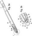
Die
Die Verlängerungsvorrichtung
Ein jeweiliges Schaltenteil
Wie eingangs beschrieben wird das betreffende Schalenteil
Insgesamt ist hier durch eine bezüglich aller Freiheitsgrade formschlüssige Betriebsverbindung geschaffen, die dadurch gelöst werden kann, das das Federelement
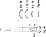
Das Schalenteil
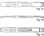
Das weitere Ausführungsbeispiel gemäß
Bei der beispielhaften Ausführungsform nach
Bei der Ausführungsform nach
ZITATE ENTHALTEN IN DER BESCHREIBUNG QUOTES INCLUDE IN THE DESCRIPTION
Diese Liste der vom Anmelder aufgeführten Dokumente wurde automatisiert erzeugt und ist ausschließlich zur besseren Information des Lesers aufgenommen. Die Liste ist nicht Bestandteil der deutschen Patent- bzw. Gebrauchsmusteranmeldung. Das DPMA übernimmt keinerlei Haftung für etwaige Fehler oder Auslassungen.This list of the documents listed by the applicant has been generated automatically and is included solely for the better information of the reader. The list is not part of the German patent or utility model application. The DPMA assumes no liability for any errors or omissions.
Zitierte PatentliteraturCited patent literature
- WO 2007/021588 A1 [0003]WO 2007/021588 A1 [0003]
- DE 102014225327 [0034]DE 102014225327 [0034]
Claims (29)
Translated fromGermanPriority Applications (4)
| Application Number | Priority Date | Filing Date | Title |
|---|---|---|---|
| DE102017114273.8ADE102017114273A1 (en) | 2017-06-27 | 2017-06-27 | Extension device for a bone anchor |
| US16/623,990US11849982B2 (en) | 2017-06-27 | 2018-06-15 | Extension device for a bone anchor |
| EP18734476.7AEP3644877B1 (en) | 2017-06-27 | 2018-06-15 | Extension device for a bone anchor |
| PCT/EP2018/065987WO2019001990A1 (en) | 2017-06-27 | 2018-06-15 | EXTENDING DEVICE FOR A BONE ANCHOR |
Applications Claiming Priority (1)
| Application Number | Priority Date | Filing Date | Title |
|---|---|---|---|
| DE102017114273.8ADE102017114273A1 (en) | 2017-06-27 | 2017-06-27 | Extension device for a bone anchor |
Publications (1)
| Publication Number | Publication Date |
|---|---|
| DE102017114273A1true DE102017114273A1 (en) | 2018-12-27 |
Family
ID=62750949
Family Applications (1)
| Application Number | Title | Priority Date | Filing Date |
|---|---|---|---|
| DE102017114273.8APendingDE102017114273A1 (en) | 2017-06-27 | 2017-06-27 | Extension device for a bone anchor |
Country Status (4)
| Country | Link |
|---|---|
| US (1) | US11849982B2 (en) |
| EP (1) | EP3644877B1 (en) |
| DE (1) | DE102017114273A1 (en) |
| WO (1) | WO2019001990A1 (en) |
Cited By (4)
| Publication number | Priority date | Publication date | Assignee | Title |
|---|---|---|---|---|
| DE102017124852A1 (en) | 2017-10-24 | 2018-10-31 | Silony Medical International AG | Instrument for surgical purposes |
| DE102017120110A1 (en) | 2017-08-31 | 2019-02-28 | Silony Medical International AG | Extension device for a bone anchor, in particular for a pedicle screw |
| DE102017120620A1 (en) | 2017-09-07 | 2019-03-07 | Silony Medical International AG | Bone anchor and extension device |
| EP4233750A1 (en)* | 2022-02-28 | 2023-08-30 | Globus Medical, Inc. | System for rod insertion using a screw tower |
Families Citing this family (5)
| Publication number | Priority date | Publication date | Assignee | Title |
|---|---|---|---|---|
| US9259247B2 (en) | 2013-03-14 | 2016-02-16 | Medos International Sarl | Locking compression members for use with bone anchor assemblies and methods |
| US11484350B2 (en) | 2018-12-13 | 2022-11-01 | Zimmer Biomet Spine, Inc. | Split tower for a bone anchor |
| US11559337B2 (en)* | 2018-12-14 | 2023-01-24 | Zimmer Biomet Spine, Inc. | Expended tab reinforcement sleeve |
| US12364515B2 (en) | 2021-03-05 | 2025-07-22 | Medos International Sàrl | Multi-feature polyaxial screw |
| WO2022184797A1 (en) | 2021-03-05 | 2022-09-09 | Medos International Sarl | Selectively locking polyaxial screw |
Citations (4)
| Publication number | Priority date | Publication date | Assignee | Title |
|---|---|---|---|---|
| WO2007021588A1 (en) | 2005-08-12 | 2007-02-22 | Stryker Spine | System and method for spinal implant placement |
| US20090222046A1 (en)* | 2008-02-28 | 2009-09-03 | K2M, Inc. | Minimally Invasive Retraction Device Having Removable Blades |
| US20130245705A1 (en)* | 2012-03-19 | 2013-09-19 | Warsaw Orthopedic, Inc. | Spinal implant system and method |
| DE102014225327A1 (en) | 2014-12-09 | 2016-06-09 | Silony Medical International AG | osteosynthesis |
Family Cites Families (11)
| Publication number | Priority date | Publication date | Assignee | Title |
|---|---|---|---|---|
| US7520879B2 (en)* | 2006-02-07 | 2009-04-21 | Warsaw Orthopedic, Inc. | Surgical instruments and techniques for percutaneous placement of spinal stabilization elements |
| US8235997B2 (en)* | 2008-01-29 | 2012-08-07 | Pioneer Surgical Technology, Inc. | Rod locking instrument |
| WO2010045383A2 (en)* | 2008-10-14 | 2010-04-22 | Trinity Orthopedics, Llc | Insertion and reduction tool for pedicle screw assembly |
| US8535318B2 (en)* | 2010-04-23 | 2013-09-17 | DePuy Synthes Products, LLC | Minimally invasive instrument set, devices and related methods |
| US8603094B2 (en)* | 2010-07-26 | 2013-12-10 | Spinal Usa, Inc. | Minimally invasive surgical tower access devices and related methods |
| US8439924B1 (en)* | 2012-04-02 | 2013-05-14 | Warsaw Orthopedic, Inc. | Spinal implant system and method |
| US9532814B2 (en)* | 2013-03-14 | 2017-01-03 | Globus Medical, Inc. | Instruments for use during spine surgery |
| CA2846149C (en)* | 2013-03-14 | 2018-03-20 | Stryker Spine | Systems and methods for percutaneous spinal fusion |
| US9265533B2 (en)* | 2013-09-04 | 2016-02-23 | Aesculap Implant Systems, Llc | Rod persuader, system and method |
| CN104905872B (en)* | 2015-05-12 | 2017-05-31 | 山东威高骨科材料股份有限公司 | A kind of breast-stroke clamps binding clip |
| US20190336182A1 (en)* | 2015-10-27 | 2019-11-07 | Ctl Medical Corporation | Modular rod reduction tower and related methods |
- 2017
- 2017-06-27DEDE102017114273.8Apatent/DE102017114273A1/enactivePending
- 2018
- 2018-06-15EPEP18734476.7Apatent/EP3644877B1/enactiveActive
- 2018-06-15USUS16/623,990patent/US11849982B2/enactiveActive
- 2018-06-15WOPCT/EP2018/065987patent/WO2019001990A1/ennot_activeCeased
Patent Citations (4)
| Publication number | Priority date | Publication date | Assignee | Title |
|---|---|---|---|---|
| WO2007021588A1 (en) | 2005-08-12 | 2007-02-22 | Stryker Spine | System and method for spinal implant placement |
| US20090222046A1 (en)* | 2008-02-28 | 2009-09-03 | K2M, Inc. | Minimally Invasive Retraction Device Having Removable Blades |
| US20130245705A1 (en)* | 2012-03-19 | 2013-09-19 | Warsaw Orthopedic, Inc. | Spinal implant system and method |
| DE102014225327A1 (en) | 2014-12-09 | 2016-06-09 | Silony Medical International AG | osteosynthesis |
Cited By (6)
| Publication number | Priority date | Publication date | Assignee | Title |
|---|---|---|---|---|
| DE102017120110A1 (en) | 2017-08-31 | 2019-02-28 | Silony Medical International AG | Extension device for a bone anchor, in particular for a pedicle screw |
| DE102017120110B4 (en) | 2017-08-31 | 2019-05-29 | Silony Medical International AG | Extension device for a bone anchor, in particular for a pedicle screw |
| DE102017120620A1 (en) | 2017-09-07 | 2019-03-07 | Silony Medical International AG | Bone anchor and extension device |
| DE102017120620B4 (en) | 2017-09-07 | 2019-05-29 | Silony Medical International AG | Bone anchor and extension device |
| DE102017124852A1 (en) | 2017-10-24 | 2018-10-31 | Silony Medical International AG | Instrument for surgical purposes |
| EP4233750A1 (en)* | 2022-02-28 | 2023-08-30 | Globus Medical, Inc. | System for rod insertion using a screw tower |
Also Published As
| Publication number | Publication date |
|---|---|
| US11849982B2 (en) | 2023-12-26 |
| US20200197052A1 (en) | 2020-06-25 |
| EP3644877B1 (en) | 2023-07-19 |
| EP3644877A1 (en) | 2020-05-06 |
| WO2019001990A1 (en) | 2019-01-03 |
| EP3644877C0 (en) | 2023-07-19 |
Similar Documents
| Publication | Publication Date | Title |
|---|---|---|
| EP3644877B1 (en) | Extension device for a bone anchor | |
| DE102004027881B4 (en) | Bone screw and osteosynthesis device | |
| EP2213254B1 (en) | Surgical instrument | |
| DE102018102173B3 (en) | polyaxial screw | |
| DE102016108504A1 (en) | Medical instrument for temporary fixation of a polyaxial pedicle screw | |
| DE102013107498A1 (en) | Spine stabilization system and surgical fastener for a spine stabilization system | |
| DE102013108362A1 (en) | Medical instrument for holding and manipulating a surgical fastener and spinal stabilization system | |
| DE102009037614A1 (en) | Electrosurgical instrument | |
| DE102012105264A1 (en) | Device for fixing a femur in hip endoprosthesis | |
| DE102012104207A1 (en) | assembly tool | |
| DE102019000965B4 (en) | Bone anchoring device for pedicle access | |
| EP2497433A1 (en) | Multiple trocar system | |
| DE102017120110B4 (en) | Extension device for a bone anchor, in particular for a pedicle screw | |
| EP1188416B1 (en) | Pedicle screw for intervertebral support element | |
| DE102014207900A1 (en) | Jaw part for a surgical tubular shaft instrument | |
| DE102017120619B4 (en) | Extension device for a bone screw and screwdriver instrument | |
| DE102017000222B4 (en) | Torque wrenches, in particular torque wrenches for dental applications | |
| DE102014114530A1 (en) | Locking sleeve for a pedicle screw | |
| DE102011111403A1 (en) | Tulip head screw for repositioning vertebral body with e.g. various indications, has tulip head thread whose diameter in region of outer circumferential predetermined breaking edge is greater than diameter of remaining of thread | |
| DE102023109802A1 (en) | bone clamp | |
| DE9310668U1 (en) | screwdriver | |
| DE102017120620B4 (en) | Bone anchor and extension device | |
| DE202007000427U1 (en) | Surgical handle and surgical instrument | |
| DE102017114267B4 (en) | Extension device for a bone anchor | |
| DE202019005511U1 (en) | Bone anchoring device for pedicle access |
Legal Events
| Date | Code | Title | Description |
|---|---|---|---|
| R012 | Request for examination validly filed | ||
| R016 | Response to examination communication |