DE102017113046A1 - A connection device for electrically connecting at least one line to a switch device, a connection system with a connection device, and a method for electrically connecting a line to a switch device - Google Patents
A connection device for electrically connecting at least one line to a switch device, a connection system with a connection device, and a method for electrically connecting a line to a switch deviceDownload PDFInfo
- Publication number
- DE102017113046A1 DE102017113046A1DE102017113046.2ADE102017113046ADE102017113046A1DE 102017113046 A1DE102017113046 A1DE 102017113046A1DE 102017113046 ADE102017113046 ADE 102017113046ADE 102017113046 A1DE102017113046 A1DE 102017113046A1
- Authority
- DE
- Germany
- Prior art keywords
- interface
- contact
- line
- connection
- switch
- Prior art date
- Legal status (The legal status is an assumption and is not a legal conclusion. Google has not performed a legal analysis and makes no representation as to the accuracy of the status listed.)
- Granted
Links
- 238000000034methodMethods0.000titleclaimsdescription22
- 238000006073displacement reactionMethods0.000claimsdescription8
- 230000008878couplingEffects0.000claimsdescription7
- 238000010168coupling processMethods0.000claimsdescription7
- 238000005859coupling reactionMethods0.000claimsdescription7
- 238000009413insulationMethods0.000claimsdescription7
- 238000004590computer programMethods0.000claimsdescription5
- 230000000694effectsEffects0.000claimsdescription3
- 238000013459approachMethods0.000abstractdescription12
- 238000005476solderingMethods0.000description5
- 238000004891communicationMethods0.000description4
- 238000003825pressingMethods0.000description3
- 230000005540biological transmissionEffects0.000description2
- 238000003780insertionMethods0.000description2
- 230000037431insertionEffects0.000description2
- 238000004519manufacturing processMethods0.000description2
- 229910000679solderInorganic materials0.000description2
- 238000011161developmentMethods0.000description1
- 230000018109developmental processEffects0.000description1
- 230000002349favourable effectEffects0.000description1
- 230000006870functionEffects0.000description1
- 238000012544monitoring processMethods0.000description1
- 230000003287optical effectEffects0.000description1
- 238000012545processingMethods0.000description1
- 239000004065semiconductorSubstances0.000description1
- 238000003860storageMethods0.000description1
- 238000012549trainingMethods0.000description1
Images


Classifications
- H—ELECTRICITY
- H01—ELECTRIC ELEMENTS
- H01R—ELECTRICALLY-CONDUCTIVE CONNECTIONS; STRUCTURAL ASSOCIATIONS OF A PLURALITY OF MUTUALLY-INSULATED ELECTRICAL CONNECTING ELEMENTS; COUPLING DEVICES; CURRENT COLLECTORS
- H01R11/00—Individual connecting elements providing two or more spaced connecting locations for conductive members which are, or may be, thereby interconnected, e.g. end pieces for wires or cables supported by the wire or cable and having means for facilitating electrical connection to some other wire, terminal, or conductive member, blocks of binding posts
- H01R11/11—End pieces or tapping pieces for wires, supported by the wire and for facilitating electrical connection to some other wire, terminal or conductive member
- H01R11/12—End pieces terminating in an eye, hook, or fork
- H—ELECTRICITY
- H01—ELECTRIC ELEMENTS
- H01H—ELECTRIC SWITCHES; RELAYS; SELECTORS; EMERGENCY PROTECTIVE DEVICES
- H01H11/00—Apparatus or processes specially adapted for the manufacture of electric switches
- H01H11/0006—Apparatus or processes specially adapted for the manufacture of electric switches for converting electric switches
- H01H11/0031—Apparatus or processes specially adapted for the manufacture of electric switches for converting electric switches for allowing different types or orientation of connections to contacts
- H—ELECTRICITY
- H01—ELECTRIC ELEMENTS
- H01R—ELECTRICALLY-CONDUCTIVE CONNECTIONS; STRUCTURAL ASSOCIATIONS OF A PLURALITY OF MUTUALLY-INSULATED ELECTRICAL CONNECTING ELEMENTS; COUPLING DEVICES; CURRENT COLLECTORS
- H01R4/00—Electrically-conductive connections between two or more conductive members in direct contact, i.e. touching one another; Means for effecting or maintaining such contact; Electrically-conductive connections having two or more spaced connecting locations for conductors and using contact members penetrating insulation
- H01R4/28—Clamped connections, spring connections
- H01R4/48—Clamped connections, spring connections utilising a spring, clip, or other resilient member
- H01R4/4809—Clamped connections, spring connections utilising a spring, clip, or other resilient member using a leaf spring to bias the conductor toward the busbar
- H01R4/48185—Clamped connections, spring connections utilising a spring, clip, or other resilient member using a leaf spring to bias the conductor toward the busbar adapted for axial insertion of a wire end
- H01R4/4819—Clamped connections, spring connections utilising a spring, clip, or other resilient member using a leaf spring to bias the conductor toward the busbar adapted for axial insertion of a wire end the spring shape allowing insertion of the conductor end when the spring is unbiased
- H01R4/4823—Multiblade spring
- H—ELECTRICITY
- H01—ELECTRIC ELEMENTS
- H01R—ELECTRICALLY-CONDUCTIVE CONNECTIONS; STRUCTURAL ASSOCIATIONS OF A PLURALITY OF MUTUALLY-INSULATED ELECTRICAL CONNECTING ELEMENTS; COUPLING DEVICES; CURRENT COLLECTORS
- H01R4/00—Electrically-conductive connections between two or more conductive members in direct contact, i.e. touching one another; Means for effecting or maintaining such contact; Electrically-conductive connections having two or more spaced connecting locations for conductors and using contact members penetrating insulation
- H01R4/26—Connections in which at least one of the connecting parts has projections which bite into or engage the other connecting part in order to improve the contact
- H—ELECTRICITY
- H01—ELECTRIC ELEMENTS
- H01R—ELECTRICALLY-CONDUCTIVE CONNECTIONS; STRUCTURAL ASSOCIATIONS OF A PLURALITY OF MUTUALLY-INSULATED ELECTRICAL CONNECTING ELEMENTS; COUPLING DEVICES; CURRENT COLLECTORS
- H01R4/00—Electrically-conductive connections between two or more conductive members in direct contact, i.e. touching one another; Means for effecting or maintaining such contact; Electrically-conductive connections having two or more spaced connecting locations for conductors and using contact members penetrating insulation
- H01R4/28—Clamped connections, spring connections
- H01R4/48—Clamped connections, spring connections utilising a spring, clip, or other resilient member
- H01R4/4809—Clamped connections, spring connections utilising a spring, clip, or other resilient member using a leaf spring to bias the conductor toward the busbar
- H01R4/4846—Busbar details
- H01R4/4848—Busbar integrally formed with the spring
Landscapes
- Engineering & Computer Science (AREA)
- Manufacturing & Machinery (AREA)
- Switch Cases, Indication, And Locking (AREA)
Abstract
Translated fromGerman
Description
Translated fromGermanDer hier vorgestellte Ansatz betrifft eine Verbindungsvorrichtung zum elektrischen Verbinden einer Leitung mit einer Schaltereinrichtung, ein Verbindungssystem mit einer Verbindungsvorrichtung und ein Verfahren zum elektrischen Verbinden einer Leitung mit einer Schaltereinrichtung.The approach presented here relates to a connection device for electrically connecting a line to a switch device, a connection system with a connection device and a method for electrically connecting a line to a switch device.
Zum Verbinden von Leitungen wie Litzen oder Verbindungskabeln mit einem Druckschalter eines Staubsaugers werden die Leitungen an den Druckschalter genietet und/oder es wird der Druckschalter auf einer Platine verlötet.To connect lines such as wires or connecting cables with a pressure switch of a vacuum cleaner, the lines are riveted to the pressure switch and / or it is soldered to the pressure switch on a circuit board.
Dem hier vorgestellten Ansatz liegt die Aufgabe zugrunde, eine verbesserte Verbindungsvorrichtung zum elektrischen Verbinden einer Leitung mit einer Schaltereinrichtung, ein Verbindungssystem mit einer verbesserten Verbindungsvorrichtung sowie ein verbessertes Verfahren zum elektrischen Verbinden einer Leitung mit einer Schaltereinrichtung zu schaffen.The approach presented here has the object of providing an improved connection device for electrically connecting a line to a switch device, a connection system with an improved connection device and an improved method for electrically connecting a line to a switch device.
Erfindungsgemäß wird diese Aufgabe durch eine Verbindungsvorrichtung zum elektrischen Verbinden einer Leitung mit einer Schaltereinrichtung, ferner ein Verbindungssystem mit einer Verbindungsvorrichtung und schließlich ein Verfahren zum elektrischen Verbinden einer Leitung mit einer Schaltereinrichtung mit den Merkmalen bzw. Schritten der Hauptansprüche gelöst. Gegenstand des vorliegenden Ansatzes ist auch ein Computerprogramm. Vorteilhafte Ausgestaltungen und Weiterbildungen des Ansatzes ergeben sich aus den nachfolgenden Unteransprüchen.According to the invention, this object is achieved by a connection device for electrically connecting a line to a switch device, furthermore a connection system with a connection device and finally a method for electrically connecting a line to a switch device having the features or steps of the main claims. Subject of the present approach is also a computer program. Advantageous embodiments and further developments of the approach will become apparent from the following subclaims.
Die mit dem hier vorgestellten Ansatz erreichbaren Vorteile bestehen darin, dass durch eine hier vorgestellte Verbindungsvorrichtung eine Leitung mit einer Schaltereinrichtung sicher mechanisch und ohne ein Verlöten von Komponenten verbindbar ist.The achievable with the approach presented here are that a line with a switch device safely mechanically and without soldering of components can be connected by a connecting device presented here.
Eine Verbindungsvorrichtung zum elektrischen Verbinden zumindest einer Leitung mit einer Schaltereinrichtung, beispielsweise einer Druckschaltereinrichtung, weist zumindest eine Kontakteinrichtung mit einer ersten Schnittstelle und einer zweiten Schnittstelle auf. Die erste Schnittstelle ist dazu ausgeformt, um mit der Leitung koppelbar oder gekoppelt zu sein und die zweite Schnittstelle ist dazu ausgeformt, um mit einem Kontaktstift der Schaltereinrichtung verklemmbar oder verklemmt zu sein, insbesondere wobei die zweite Schnittstelle flexibel ausgeformt ist.A connecting device for electrically connecting at least one line to a switch device, for example a pressure switch device, has at least one contact device with a first interface and a second interface. The first interface is configured to be coupled or coupled to the line, and the second interface is shaped to be clamped or jammed with a contact pin of the switch device, particularly where the second interface is flexibly formed.
Eine hier vorgestellte Verbindungsvorrichtung kann zur Verwendung in einem Staubsauger bestimmt sein, wobei die Leitung eine Litze oder ein Verbindungskabel sein kann, welche im Anschluss auf eine Kabeltrommel montiert werden kann. Zum Koppeln der Leitung mit der ersten Schnittstelle kann die Leitung an die erste Schnittstelle anschlagbar ausgeformt oder angeschlagen sein. Ein Querschnitt der Kontakteinrichtung kann bandförmig ausgeformt sein, wobei die zweite Schnittstelle in einer vorteilhaften Ausführungsform zumindest teilweise als ein Rand um eine Öffnung ausgeformt sein kann, die über den Kontaktstift stülpbar ist. Wenn eine solche zweite Schnittstelle flexibel ausgeformt ist und sich beispielsweise zudem der Rand der zweiten Schnittstelle aus einer Haupterstreckungsebene der Kontakteinrichtung hervor erhebt, schafft dies eine sichere formschlüssige Verbindung zwischen dem Kontaktstift und der Verbindungsvorrichtung, wenn die Kontakteinrichtung zum Verklemmen mit dem Kontaktstift auf den Kontaktstift aufgezogen ist. Hierbei ist es von Vorteil, wenn die zweite Schnittstelle von einem der Schaltereinrichtung abgewandt angeordneten freien Ende des Kontaktstifts über den Kontaktstift gezogen werden kann, wodurch sich der flexible Rand um den Kontaktstift legen kann und sich beim Herabziehen der Kontakteinrichtung in Richtung der Schaltereinrichtung, oder beim Einführen des Kontaktstifts in die Öffnung, ebenfalls in Richtung des freien Endes des Kontaktstifts hervor erhebt. Eine solche Kontakteinrichtung kann vorteilhafterweise einen Klemm-Kontakt, insbesondere einen Schneid-Klemm-Kontakt ausformen, der die Verbindungsvorrichtung gegen ein Lösen von dem Kontaktstift sichert.A connecting device presented herein may be intended for use in a vacuum cleaner, wherein the conduit may be a stranded wire or a connecting cable which may subsequently be mounted on a cable drum. For coupling the line to the first interface, the line may be formed or hinged to the first interface. A cross-section of the contact device can be shaped like a ribbon, wherein the second interface can be formed in an advantageous embodiment, at least partially as an edge around an opening which can be folded over the contact pin. If such a second interface is formed in a flexible manner and, for example, the edge of the second interface protrudes from a main extension plane of the contact device, this creates a secure positive connection between the contact pin and the connecting device when the contact device is mounted on the contact pin for clamping with the contact pin is. In this case, it is advantageous if the second interface can be pulled over the contact pin from a free end of the contact pin arranged facing away from the switch device, as a result of which the flexible edge can lie around the contact pin and move downwards when the contact device is pulled in the direction of the switch device or Insertion of the contact pin in the opening, also in the direction of the free end of the contact pin protrudes. Such a contact device can advantageously form a clamping contact, in particular an insulation displacement contact, which secures the connection device against loosening of the contact pin.
Zum Stabilisieren und Schützen der Kontakteinrichtung kann die Verbindungsvorrichtung eine Gehäuseeinrichtung aufweisen, in der die Kontakteinrichtung zumindest teilweise aufgenommen ist. Die Gehäuseeinrichtung kann eine Durchgangsöffnung zum Einführen des Kontaktstifts aufweisen, insbesondere wobei die zweite Schnittstelle der Kontakteinrichtung angeordnet sein kann, um zumindest teilweise in die Durchgangsöffnung hineinzuragen. Eine solche Gehäuseeinrichtung kann die Verbindungsvorrichtung auch radial um den Kontaktstift herum stabilisieren, wenn die Verbindungsvorrichtung wie beschrieben über den Kontaktstift gezogen angeordnet ist.To stabilize and protect the contact device, the connecting device may have a housing device, in which the contact device is at least partially accommodated. The housing device may have a through opening for insertion of the contact pin, in particular wherein the second interface of the contact device may be arranged to at least partially project into the through opening. Such a housing means may also stabilize the connection device radially around the contact pin when the connection device is arranged pulled over the contact pin as described.
Es ist weiterhin von Vorteil, wenn die Verbindungsvorrichtung ein Gehäuseelement aufweist, das in der Durchgangsöffnung aufgenommen oder aufnehmbar ist, wobei zumindest ein an die Durchgangsöffnung angrenzender Randabschnitt des Gehäuseelements dazu ausgeformt sein kann, um die zweite Schnittstelle flexibel zwischen dem Gehäuseelement und der Gehäuseeinrichtung einzuspannen. Das Gehäuseelement kann ein lösbares Bauteil sein, das beispielsweise zum Fixieren der zweiten Schnittstelle über den Kontaktstift auf die Gehäuseeinrichtung befestigbar, beispielsweise aufsteckbar, ausgeformt ist. Wenn die zweite Schnittstelle durch das Gehäuseelement in Richtung des freien Endes des Kontaktstifts flexibel eingespannt ist, kann dies beim Aufdrücken Toleranzen der Bauteile ausgleichen. Des Weiteren wird so eine Zugentlastung für eine Kontaktstelle gewährleistet.It is furthermore advantageous if the connection device has a housing element which is received or receivable in the passage opening, wherein at least one edge section of the housing element adjoining the passage opening can be formed to flexibly clamp the second interface between the housing element and the housing device. The housing element may be a detachable component, which may be fastened, for example attachable, for fastening the second interface via the contact pin to the housing device. If the second interface through the Housing element is flexibly clamped in the direction of the free end of the contact pin, this can compensate for pressing tolerances of the components. Furthermore, this ensures a strain relief for a contact point.
Zum Fixieren der Kontakteinrichtung an der Gehäuseeinrichtung kann die Kontakteinrichtung eine dritte Schnittstelle aufweisen, die dazu ausgeformt ist, um mit der Gehäuseeinrichtung verschraubbar und/oder vernietbar zu sein.For fixing the contact device to the housing device, the contact device may have a third interface, which is shaped to be screwed and / or riveted to the housing device.
Gemäß einer weiteren vorteilhaften Ausführungsform kann die Verbindungsvorrichtung eine weitere Kontakteinrichtung aufweisen, die zumindest eine vierte Schnittstelle und eine fünfte Schnittstelle aufweist, wobei die vierte Schnittstelle dazu ausgeformt ist, um mit einer weiteren Leitung koppelbar oder gekoppelt zu sein und die fünfte Schnittstelle dazu ausgeformt ist, um mit einem weiteren Kontaktstift der Schaltereinrichtung verklemmbar oder verklemmt zu sein, um die weitere Leitung mit der Schaltereinrichtung elektrisch zu verbinden, insbesondere wobei die fünfte Schnittstelle flexibel ausgeformt sein kann. Die weitere Kontakteinrichtung kann des Weiteren entsprechend einer der beschriebenen Varianten der Kontakteinrichtung ausgeformt sein. Eine solche weitere Kontakteinrichtung schafft eine zusätzliche elektrische Verbindung zu der Steckereinrichtung.According to a further advantageous embodiment, the connection device can have a further contact device, which has at least a fourth interface and a fifth interface, wherein the fourth interface is designed to be coupled or coupled to a further line and the fifth interface is formed, to be clamped or jammed with another contact pin of the switch device to electrically connect the further line to the switch device, in particular wherein the fifth interface can be flexibly formed. The further contact device can furthermore be shaped in accordance with one of the variants of the contact device described. Such a further contact device creates an additional electrical connection to the plug device.
Ein Verbindungssystem weist eine der vorgestellten Verbindungsvorrichtungen und zumindest eine Leitung und/oder einen Kontaktstift einer Schaltereinrichtung auf. Die erste Schnittstelle der Verbindungsvorrichtung ist dabei mit der Leitung gekoppelt und/oder die zweite Schnittstelle mit dem Kontaktstift verklemmt, um die Leitung mit der Schaltereinrichtung elektrisch zu verbinden. Ein solches Verbindungssystem kann als Ersatz für bekannte Verbindungssysteme zum Verbinden von Leitungen mit einer Schaltereinrichtung in einem Staubsauger dienen, wobei das hier vorgestellte Verbindungssystem dank der Verbindungsvorrichtung während einer Montage vorteilhafterweise keinen Lötprozess erfordert.A connection system has one of the presented connection devices and at least one line and / or a contact pin of a switch device. The first interface of the connection device is coupled to the line and / or the second interface is clamped to the contact pin to electrically connect the line to the switch device. Such a connection system can serve as a replacement for known connection systems for connecting lines to a switch device in a vacuum cleaner, wherein the connection system presented here advantageously does not require a soldering process thanks to the connection device during assembly.
Ein Verfahren zum elektrischen Verbinden einer Leitung mit einer Schaltereinrichtung umfasst zumindest die folgenden Schritte:
- Koppeln der Leitung mit einer ersten Schnittstelle einer der vorgestellten Verbindungsvorrichtungen; und
- Verklemmen der zweiten Schnittstelle der Verbindungsvorrichtung mit einem Kontaktstift der Schaltereinrichtung, um die Leitung mit der Schaltereinrichtung elektrisch zu verbinden.
- Coupling the line to a first interface of one of the presented connection devices; and
- Clamping the second interface of the connector with a contact pin of the switch means to electrically connect the lead to the switch means.
Im Schritt des Verklemmens kann eine Gehäuseeinrichtung der Verbindungsvorrichtung auf eine weitere Gehäuseeinrichtung der Schaltereinrichtung aufgepresst werden, um ein Verklemmen der zweiten Schnittstelle mit dem Kontaktstift zu bewirken.In the step of clamping, a housing device of the connecting device can be pressed onto a further housing device of the switch device in order to effect jamming of the second interface with the contact pin.
Dieses Verfahren kann unter Verwendung einer der zuvor vorgestellten Verbindungsvorrichtungen ausführbar sein. Auch durch ein solches Verfahren können die bereits beschriebenen Vorteile der Verbindungsvorrichtung technisch einfach und kostengünstig realisiert werden.This method may be practicable using one of the previously presented connection devices. Also by such a method, the already described advantages of the connecting device can be realized technically simple and inexpensive.
Der hier vorgestellte Ansatz schafft ferner eine Vorrichtung, die ausgebildet ist, um die Schritte einer Variante eines hier vorgestellten Verfahrens in entsprechenden Einrichtungen durchzuführen, anzusteuern bzw. umzusetzen. Auch durch diese Ausführungsvariante des Ansatzes in Form einer Vorrichtung kann die dem Ansatz zugrunde liegende Aufgabe schnell und effizient gelöst werden.The approach presented here also creates a device that is designed to perform the steps of a variant of a method presented here in appropriate facilities to drive or implement. Also by this embodiment of the approach in the form of a device, the approach underlying the approach can be solved quickly and efficiently.
Hierzu kann die Vorrichtung zumindest eine Recheneinheit zum Verarbeiten von Signalen oder Daten, zumindest eine Speichereinheit zum Speichern von Signalen oder Daten, zumindest eine Schnittstelle zu einem Sensor oder einem Aktor zum Einlesen von Sensorsignalen von dem Sensor oder zum Ausgeben von Daten- oder Steuersignalen an den Aktor und/oder zumindest eine Kommunikationsschnittstelle zum Einlesen oder Ausgeben von Daten aufweisen, die in ein Kommunikationsprotokoll eingebettet sind. Die Recheneinheit kann beispielsweise ein Signalprozessor, ein Mikrocontroller oder dergleichen sein, wobei die Speichereinheit ein Flash-Speicher, ein EPROM oder eine magnetische Speichereinheit sein kann. Die Kommunikationsschnittstelle kann ausgebildet sein, um Daten drahtlos und/oder leitungsgebunden einzulesen oder auszugeben, wobei eine Kommunikationsschnittstelle, die leitungsgebundene Daten einlesen oder ausgeben kann, diese Daten beispielsweise elektrisch oder optisch aus einer entsprechenden Datenübertragungsleitung einlesen oder in eine entsprechende Datenübertragungsleitung ausgeben kann.For this purpose, the device may comprise at least one computing unit for processing signals or data, at least one memory unit for storing signals or data, at least one interface to a sensor or an actuator for reading sensor signals from the sensor or for outputting data or control signals to the sensor Actuator and / or at least one communication interface for reading or outputting data embedded in a communication protocol. The arithmetic unit may be, for example, a signal processor, a microcontroller or the like, wherein the memory unit may be a flash memory, an EPROM or a magnetic memory unit. The communication interface can be designed to read or output data wirelessly and / or by line, wherein a communication interface that can read or output line-bound data, for example, electrically or optically read this data from a corresponding data transmission line or output in a corresponding data transmission line.
Unter einer Vorrichtung kann vorliegend ein elektrisches Gerät verstanden werden, das Sensorsignale verarbeitet und in Abhängigkeit davon Steuer- und/oder Datensignale ausgibt. Die Vorrichtung kann eine Schnittstelle aufweisen, die hard- und/oder softwaremäßig ausgebildet sein kann. Bei einer hardwaremäßigen Ausbildung können die Schnittstellen beispielsweise Teil eines sogenannten System-ASICs sein, der verschiedenste Funktionen der Vorrichtung beinhaltet. Es ist jedoch auch möglich, dass die Schnittstellen eigene, integrierte Schaltkreise sind oder zumindest teilweise aus diskreten Bauelementen bestehen. Bei einer softwaremäßigen Ausbildung können die Schnittstellen Softwaremodule sein, die beispielsweise auf einem Mikrocontroller neben anderen Softwaremodulen vorhanden sind.In the present case, a device can be understood as meaning an electrical device which processes sensor signals and outputs control and / or data signals in dependence thereon. The device may have an interface, which may be formed in hardware and / or software. In the case of a hardware-based embodiment, the interfaces can be part of a so-called system ASIC, for example, which contains a wide variety of functions of the device. However, it is also possible that the interfaces are their own integrated circuits or at least partially consist of discrete components. In a software-based Training, the interfaces may be software modules that are present for example on a microcontroller in addition to other software modules.
In einer vorteilhaften Ausgestaltung erfolgt durch die Vorrichtung eine Steuerung eines elektrischen Verbindens einer Leitung mit einer Schaltereinrichtung. Hierzu kann die Vorrichtung beispielsweise auf Sensorsignale wie ein Koppelsignal und ein Verklemmsignal zugreifen. Die Ansteuerung erfolgt über Aktoren wie eine Kopplungseinrichtung und eine Verklemmeinrichtung.In an advantageous embodiment, the device is used to control electrical connection of a line to a switch device. For this purpose, the device can access, for example, sensor signals such as a coupling signal and a jamming signal. The control takes place via actuators such as a coupling device and a Verklemmeinrichtung.
Von Vorteil ist auch ein Computerprogrammprodukt oder Computerprogramm mit Programmcode, der auf einem maschinenlesbaren Träger oder Speichermedium wie einem Halbleiterspeicher, einem Festplattenspeicher oder einem optischen Speicher gespeichert sein kann und zur Durchführung, Umsetzung und/oder Ansteuerung der Schritte des Verfahrens nach einer der vorstehend beschriebenen Ausführungsformen verwendet wird, insbesondere wenn das Programmprodukt oder Programm auf einem Computer oder einer Vorrichtung ausgeführt wird.Also of advantage is a computer program product or computer program with program code which can be stored on a machine-readable carrier or storage medium such as a semiconductor memory, a hard disk memory or an optical memory and for carrying out, implementing and / or controlling the steps of the method according to one of the embodiments described above is used, especially when the program product or program is executed on a computer or a device.
Ausführungsbeispiele des Ansatzes sind in den Zeichnungen rein schematisch dargestellt und werden nachfolgend näher beschrieben. Es zeigt
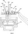
1 eine seitliche Querschnittdarstellung eines Verbindungssystems mit einer Verbindungsvorrichtung zum elektrischen Verbinden einer Leitung mit einer Schaltereinrichtung gemäß einem Ausführungsbeispiel;2 eine seitliche Querschnittdarstellung einer Verbindungsvorrichtung gemäß einem Ausführungsbeispiel;3 eine perspektivische Aufsicht auf ein Verbindungssystem gemäß einem Ausführungsbeispiel; und4 ein Ablaufdiagramm eines Verfahrens zum elektrischen Verbinden einer Leitung mit einer Schaltereinrichtung gemäß einem Ausführungsbeispiel.
1 a side cross-sectional view of a connection system with a connection device for electrically connecting a line with a switch device according to an embodiment;2 a side cross-sectional view of a connecting device according to an embodiment;3 a perspective view of a connection system according to an embodiment; and4 a flowchart of a method for electrically connecting a line with a switch device according to an embodiment.
In der nachfolgenden Beschreibung günstiger Ausführungsbeispiele des vorliegenden Ansatzes werden für die in den verschiedenen Figuren dargestellten und ähnlich wirkenden Elemente gleiche oder ähnliche Bezugszeichen verwendet, wobei auf eine wiederholte Beschreibung dieser Elemente verzichtet wird.In the following description of favorable embodiments of the present approach, the same or similar reference numerals are used for the elements shown in the various figures and similar acting, with a repeated description of these elements is omitted.
Das Verbindungssystem
Die Verbindungsvorrichtung
Die im Folgenden beschriebenen Merkmale der Verbindungsvorrichtung
Ein Querschnitt der Kontakteinrichtung
Zum Verklemmen der zweiten Schnittstelle
Die Verbindungsvorrichtung
Gemäß diesem Ausführungsbeispiel weist die Kontakteinrichtung
Im Folgenden werden Ausführungsbeispiele anhand der
Die hier vorgestellte Verbindungsvorrichtung
Als eine Basis für das Verbindungssystem
Vorteile der Verbindungsvorrichtung
Die weitere Kontakteinrichtung
Die Gehäuseeinrichtung
Das Verfahren
Gemäß diesem Ausführungsbeispiel wird im Schritt
Die hier vorgestellten Verfahrensschritte können wiederholt sowie in einer anderen als in der beschriebenen Reihenfolge ausgeführt werden.The method steps presented here can be repeated and executed in a sequence other than that described.
Umfasst ein Ausführungsbeispiel eine „und/oder“-Verknüpfung zwischen einem ersten Merkmal und einem zweiten Merkmal, so ist dies so zu lesen, dass das Ausführungsbeispiel gemäß einer Ausführungsform sowohl das erste Merkmal als auch das zweite Merkmal und gemäß einer weiteren Ausführungsform entweder nur das erste Merkmal oder nur das zweite Merkmal aufweist.If an exemplary embodiment comprises a "and / or" link between a first feature and a second feature, then this is to be read so that the embodiment according to one embodiment, both the first feature and the second feature and according to another embodiment either only first feature or only the second feature.
Claims (14)
Translated fromGermanPriority Applications (1)
| Application Number | Priority Date | Filing Date | Title |
|---|---|---|---|
| DE102017113046.2ADE102017113046B4 (en) | 2017-06-14 | 2017-06-14 | Connection device for electrically connecting at least one line to a switch device and connection system to a connection device |
Applications Claiming Priority (1)
| Application Number | Priority Date | Filing Date | Title |
|---|---|---|---|
| DE102017113046.2ADE102017113046B4 (en) | 2017-06-14 | 2017-06-14 | Connection device for electrically connecting at least one line to a switch device and connection system to a connection device |
Publications (2)
| Publication Number | Publication Date |
|---|---|
| DE102017113046A1true DE102017113046A1 (en) | 2018-12-20 |
| DE102017113046B4 DE102017113046B4 (en) | 2024-03-28 |
Family
ID=64457244
Family Applications (1)
| Application Number | Title | Priority Date | Filing Date |
|---|---|---|---|
| DE102017113046.2AActiveDE102017113046B4 (en) | 2017-06-14 | 2017-06-14 | Connection device for electrically connecting at least one line to a switch device and connection system to a connection device |
Country Status (1)
| Country | Link |
|---|---|
| DE (1) | DE102017113046B4 (en) |
Citations (8)
| Publication number | Priority date | Publication date | Assignee | Title |
|---|---|---|---|---|
| US3768062A (en)* | 1971-09-28 | 1973-10-23 | Molex Inc | Terminal for flexible circuits |
| US6520812B1 (en)* | 2000-08-30 | 2003-02-18 | Antaya Technologies Corporation | Connector terminal with resilient contacts |
| US6527571B2 (en)* | 1998-11-30 | 2003-03-04 | Sumitomo Wiring Systems, Ltd. | Electrical connecting configuration |
| DE60000963T2 (en)* | 2000-02-10 | 2003-09-11 | Hager-Electro S.A., Obernai | Separable terminal block for a modular electrical device |
| DE102004043468A1 (en)* | 2004-09-08 | 2006-03-30 | Siemens Ag | Switchgear with pluggable connections |
| DE102005027824A1 (en)* | 2005-06-15 | 2006-12-28 | Moeller Gmbh | Plug-in device for an electrical switching device |
| DE102005029325B4 (en)* | 2005-06-24 | 2007-04-05 | Junghans Feinwerktechnik Gmbh & Co. Kg | Contact connection of a detonator electronics |
| US20110151728A1 (en)* | 2009-12-22 | 2011-06-23 | Pekka Simeon Astola | Electrical connector assembly |
- 2017
- 2017-06-14DEDE102017113046.2Apatent/DE102017113046B4/enactiveActive
Patent Citations (8)
| Publication number | Priority date | Publication date | Assignee | Title |
|---|---|---|---|---|
| US3768062A (en)* | 1971-09-28 | 1973-10-23 | Molex Inc | Terminal for flexible circuits |
| US6527571B2 (en)* | 1998-11-30 | 2003-03-04 | Sumitomo Wiring Systems, Ltd. | Electrical connecting configuration |
| DE60000963T2 (en)* | 2000-02-10 | 2003-09-11 | Hager-Electro S.A., Obernai | Separable terminal block for a modular electrical device |
| US6520812B1 (en)* | 2000-08-30 | 2003-02-18 | Antaya Technologies Corporation | Connector terminal with resilient contacts |
| DE102004043468A1 (en)* | 2004-09-08 | 2006-03-30 | Siemens Ag | Switchgear with pluggable connections |
| DE102005027824A1 (en)* | 2005-06-15 | 2006-12-28 | Moeller Gmbh | Plug-in device for an electrical switching device |
| DE102005029325B4 (en)* | 2005-06-24 | 2007-04-05 | Junghans Feinwerktechnik Gmbh & Co. Kg | Contact connection of a detonator electronics |
| US20110151728A1 (en)* | 2009-12-22 | 2011-06-23 | Pekka Simeon Astola | Electrical connector assembly |
Also Published As
| Publication number | Publication date |
|---|---|
| DE102017113046B4 (en) | 2024-03-28 |
Similar Documents
| Publication | Publication Date | Title |
|---|---|---|
| DE102017222543A1 (en) | Spring clip for attaching to an electrical conductor of an electrical machine | |
| EP3625857B1 (en) | Strain and pressure relief means in a plug connector housing | |
| DE102009045438A1 (en) | Wiring harness and ECU system | |
| DE102007035973A1 (en) | mounting structure | |
| DE202018006437U1 (en) | Spring-cage connection and circular connector with a variety of spring-cage connections | |
| DE102018210892B4 (en) | Plug connection element for a motor vehicle and method for producing such a plug connection element | |
| DE102010038465A1 (en) | Electrical connection | |
| DE102018108968A1 (en) | Shielded connector module for a modular industrial connector | |
| DE102017215729A1 (en) | Connecting device and method for electrically connecting an electric motor with an electronic switching unit, electronic switching unit, connecting unit and device system with at least one connecting device | |
| DE202017100608U1 (en) | Connectors | |
| DE112015000756T5 (en) | Collective connector and wiring harness | |
| EP2686917B1 (en) | Direct connector comprising a housing and at least a direct contact and electrical arrangement comprisng such connector | |
| DE102017126185A1 (en) | Contact element with a clamping connection for stranded conductors | |
| DE102017113046A1 (en) | A connection device for electrically connecting at least one line to a switch device, a connection system with a connection device, and a method for electrically connecting a line to a switch device | |
| DE102011056553A1 (en) | Plug with indicator member and on a line attachable separator | |
| DE102012203842B3 (en) | Slip ring brush and slip ring brush holder | |
| AT503637B1 (en) | CABLE WITH CONNECTOR, CONNECTOR FOR A CABLE AND METHOD FOR CONNECTING A CABLE WITH A CONNECTOR | |
| DE202019105026U1 (en) | Connection adapter for a drive device | |
| DE202019104333U1 (en) | Improved terminal block structure | |
| DE202016101579U1 (en) | Capacitive sensor module for a connector | |
| DE102013007815A1 (en) | Swiveling connector and contacting method | |
| DE102012216895B3 (en) | Method for assembling network conduit that is utilized for transmission of data in computer network in e.g. building, involves placing contacts in attachable element, and gripping attachable element by gripper to twist lines | |
| DE102010040595A1 (en) | Connection system and receiving unit for a control unit | |
| DE102022103338B4 (en) | Electrical connector system of a motor vehicle and motor vehicle | |
| DE102007037283A1 (en) | Cable receiving device and contact system |
Legal Events
| Date | Code | Title | Description |
|---|---|---|---|
| R012 | Request for examination validly filed | ||
| R016 | Response to examination communication | ||
| R016 | Response to examination communication | ||
| R018 | Grant decision by examination section/examining division | ||
| R020 | Patent grant now final |