DE102017107259A1 - Skull bone segment positioning device, positioning device manufacturing method and positioning device system with attachment devices - Google Patents
Skull bone segment positioning device, positioning device manufacturing method and positioning device system with attachment devicesDownload PDFInfo
- Publication number
- DE102017107259A1 DE102017107259A1DE102017107259.4ADE102017107259ADE102017107259A1DE 102017107259 A1DE102017107259 A1DE 102017107259A1DE 102017107259 ADE102017107259 ADE 102017107259ADE 102017107259 A1DE102017107259 A1DE 102017107259A1
- Authority
- DE
- Germany
- Prior art keywords
- positioning device
- cranial bone
- main body
- skull
- cranial
- Prior art date
- Legal status (The legal status is an assumption and is not a legal conclusion. Google has not performed a legal analysis and makes no representation as to the accuracy of the status listed.)
- Withdrawn
Links
- 210000003625skullAnatomy0.000titleclaimsabstractdescription69
- 238000004519manufacturing processMethods0.000titleclaimsabstractdescription17
- 210000000988bone and boneAnatomy0.000claimsabstractdescription90
- 230000002093peripheral effectEffects0.000claimsdescription2
- 230000008719thickeningEffects0.000description17
- 230000008878couplingEffects0.000description12
- 238000010168coupling processMethods0.000description12
- 238000005859coupling reactionMethods0.000description12
- 230000002349favourable effectEffects0.000description7
- 230000013011matingEffects0.000description4
- 238000000034methodMethods0.000description4
- 239000004033plasticSubstances0.000description3
- 229920003023plasticPolymers0.000description3
- 239000004952PolyamideSubstances0.000description2
- 230000008901benefitEffects0.000description2
- 230000005540biological transmissionEffects0.000description2
- 238000004364calculation methodMethods0.000description2
- 239000011248coating agentSubstances0.000description2
- 238000000576coating methodMethods0.000description2
- 238000012937correctionMethods0.000description2
- 239000003550markerSubstances0.000description2
- 238000005259measurementMethods0.000description2
- 229920002647polyamidePolymers0.000description2
- 238000012545processingMethods0.000description2
- BUHVIAUBTBOHAG-FOYDDCNASA-N(2r,3r,4s,5r)-2-[6-[[2-(3,5-dimethoxyphenyl)-2-(2-methylphenyl)ethyl]amino]purin-9-yl]-5-(hydroxymethyl)oxolane-3,4-diolChemical compoundCOC1=CC(OC)=CC(C(CNC=2C=3N=CN(C=3N=CN=2)[C@H]2[C@@H]([C@H](O)[C@@H](CO)O2)O)C=2C(=CC=CC=2)C)=C1BUHVIAUBTBOHAG-FOYDDCNASA-N0.000description1
- 2380000101463D printingMethods0.000description1
- 206010000210abortionDiseases0.000description1
- 239000000654additiveSubstances0.000description1
- 230000000996additive effectEffects0.000description1
- 238000013461designMethods0.000description1
- 208000037265diseases, disorders, signs and symptomsDiseases0.000description1
- 239000007943implantSubstances0.000description1
- 238000005375photometryMethods0.000description1
- 238000002360preparation methodMethods0.000description1
- 230000002265preventionEffects0.000description1
- 230000008569processEffects0.000description1
- 230000009467reductionEffects0.000description1
- 230000003716rejuvenationEffects0.000description1
- 238000010972statistical evaluationMethods0.000description1
- 238000001356surgical procedureMethods0.000description1
- 238000012546transferMethods0.000description1
Images


Classifications
- A—HUMAN NECESSITIES
- A61—MEDICAL OR VETERINARY SCIENCE; HYGIENE
- A61B—DIAGNOSIS; SURGERY; IDENTIFICATION
- A61B17/00—Surgical instruments, devices or methods
- A61B17/56—Surgical instruments or methods for treatment of bones or joints; Devices specially adapted therefor
- A61B17/58—Surgical instruments or methods for treatment of bones or joints; Devices specially adapted therefor for osteosynthesis, e.g. bone plates, screws or setting implements
- A61B17/88—Osteosynthesis instruments; Methods or means for implanting or extracting internal or external fixation devices
- A61B17/8872—Instruments for putting said fixation devices against or away from the bone
- A—HUMAN NECESSITIES
- A61—MEDICAL OR VETERINARY SCIENCE; HYGIENE
- A61B—DIAGNOSIS; SURGERY; IDENTIFICATION
- A61B17/00—Surgical instruments, devices or methods
- A61B17/56—Surgical instruments or methods for treatment of bones or joints; Devices specially adapted therefor
- A61B17/58—Surgical instruments or methods for treatment of bones or joints; Devices specially adapted therefor for osteosynthesis, e.g. bone plates, screws or setting implements
- A61B17/68—Internal fixation devices, including fasteners and spinal fixators, even if a part thereof projects from the skin
- A61B17/688—Internal fixation devices, including fasteners and spinal fixators, even if a part thereof projects from the skin for reattaching pieces of the skull
- A—HUMAN NECESSITIES
- A61—MEDICAL OR VETERINARY SCIENCE; HYGIENE
- A61B—DIAGNOSIS; SURGERY; IDENTIFICATION
- A61B17/00—Surgical instruments, devices or methods
- A61B17/56—Surgical instruments or methods for treatment of bones or joints; Devices specially adapted therefor
- A61B17/58—Surgical instruments or methods for treatment of bones or joints; Devices specially adapted therefor for osteosynthesis, e.g. bone plates, screws or setting implements
- A61B17/68—Internal fixation devices, including fasteners and spinal fixators, even if a part thereof projects from the skin
- A61B17/80—Cortical plates, i.e. bone plates; Instruments for holding or positioning cortical plates, or for compressing bones attached to cortical plates
- A61B17/8061—Cortical plates, i.e. bone plates; Instruments for holding or positioning cortical plates, or for compressing bones attached to cortical plates specially adapted for particular bones
- A—HUMAN NECESSITIES
- A61—MEDICAL OR VETERINARY SCIENCE; HYGIENE
- A61B—DIAGNOSIS; SURGERY; IDENTIFICATION
- A61B17/00—Surgical instruments, devices or methods
- A61B17/56—Surgical instruments or methods for treatment of bones or joints; Devices specially adapted therefor
- A61B17/58—Surgical instruments or methods for treatment of bones or joints; Devices specially adapted therefor for osteosynthesis, e.g. bone plates, screws or setting implements
- A61B17/88—Osteosynthesis instruments; Methods or means for implanting or extracting internal or external fixation devices
- A61B17/8866—Osteosynthesis instruments; Methods or means for implanting or extracting internal or external fixation devices for gripping or pushing bones, e.g. approximators
- A—HUMAN NECESSITIES
- A61—MEDICAL OR VETERINARY SCIENCE; HYGIENE
- A61B—DIAGNOSIS; SURGERY; IDENTIFICATION
- A61B90/00—Instruments, implements or accessories specially adapted for surgery or diagnosis and not covered by any of the groups A61B1/00 - A61B50/00, e.g. for luxation treatment or for protecting wound edges
- A61B90/10—Instruments, implements or accessories specially adapted for surgery or diagnosis and not covered by any of the groups A61B1/00 - A61B50/00, e.g. for luxation treatment or for protecting wound edges for stereotaxic surgery, e.g. frame-based stereotaxis
- A61B90/14—Fixators for body parts, e.g. skull clamps; Constructional details of fixators, e.g. pins
- A—HUMAN NECESSITIES
- A61—MEDICAL OR VETERINARY SCIENCE; HYGIENE
- A61B—DIAGNOSIS; SURGERY; IDENTIFICATION
- A61B17/00—Surgical instruments, devices or methods
- A61B17/56—Surgical instruments or methods for treatment of bones or joints; Devices specially adapted therefor
- A61B2017/568—Surgical instruments or methods for treatment of bones or joints; Devices specially adapted therefor produced with shape and dimensions specific for an individual patient
Landscapes
- Health & Medical Sciences (AREA)
- Orthopedic Medicine & Surgery (AREA)
- Life Sciences & Earth Sciences (AREA)
- Surgery (AREA)
- Animal Behavior & Ethology (AREA)
- Veterinary Medicine (AREA)
- Biomedical Technology (AREA)
- Heart & Thoracic Surgery (AREA)
- Medical Informatics (AREA)
- Molecular Biology (AREA)
- Nuclear Medicine, Radiotherapy & Molecular Imaging (AREA)
- General Health & Medical Sciences (AREA)
- Public Health (AREA)
- Engineering & Computer Science (AREA)
- Neurology (AREA)
- Neurosurgery (AREA)
- Oral & Maxillofacial Surgery (AREA)
- Pathology (AREA)
- Surgical Instruments (AREA)
- Prostheses (AREA)
- Apparatus For Radiation Diagnosis (AREA)
- Tyre Moulding (AREA)
- Butt Welding And Welding Of Specific Article (AREA)
Abstract
Translated fromGermanDescription
Translated fromGermanDie Erfindung betrifft eine Positioniervorrichtung für Schädelknochenabschnitte zum Relativpositionieren der Schädelknochenabschnitte zueinander und zum Erhalten einer vordefinierten Gesamtform und Gesamtkontur, um eine Zielschädelform zu erreichen, mit einem zum Tragen der Schädelknochenabschnitte ausgelegten Hauptkörper. Weiterhin betrifft die Erfindung ein Herstellverfahren zum Erzeugen einer Positioniervorrichtung und eine Positioniervorrichtung an der zum Positionieren von Schädelknochenabschnitten ein oder mehrere Befestigungsvorrichtungen angebracht sind oder anbringbar sind, wobei die Befestigungsvorrichtung(en), ausgelegt ist/sind, um die Schädelknochenabschnitte temporär an der Positioniervorrichtung zu befestigen.The invention relates to a cranial bone portion positioning device for relatively positioning the cranial bone portions relative to each other and for obtaining a predefined overall shape and contour to achieve a target skull shape having a main body adapted to support the cranial bone portions. Furthermore, the invention relates to a manufacturing method for producing a positioning device and a positioning device to which one or more attachment devices are attached or attachable for positioning cranial bone sections, wherein the attachment device (s) is / are adapted to temporarily secure the cranial bone sections to the positioning device ,
Zum Korrigieren von Schädeldeformierungen werden zumeist die deformierten Schädelknochenabschnitte durch einen chirurgischen Eingriff in eine undeformierte Form gebracht.To correct skull deformations, the deformed cranial bone sections are usually brought into an undeformed shape by a surgical procedure.
Aus dem Stand der Technik sind bereits Vorrichtungen zum Ausrichten (und Korrigieren) von deformierten Schädelknochenabschnitten bekannt. Unter anderem offenbart die
Der Stand der Technik hat jedoch immer den Nachteil, dass zu der Reposition der Schädelknochenabschnitte Positioniervorrichtungen verwendet werden, die das Modell eines durchschnittlichen Kinderschädels darstellen. Aber auch bei einer großen Auswahl von Schädelmodellen stimmt der individuelle Sollschädel nur teilweise oder größtenteils mit dem Durchschnittsmodell überein. Da die Abweichungen eines Individualschädels jedoch von einem nächstähnlichen, durchschnittlichen Modell sehr groß sind, kann kein optimales Ergebnis bei der Modellierung der Schädelknochenabschnitte erzielt werden. Der Erfolg der Operation ist dann von dem Geschick und dem Können des Operateurs abhängig.However, the prior art always has the disadvantage that positioning devices that represent the model of an average pediatric skull are used for the reduction of the skull bone sections. But even with a large selection of skull models, the individual skull is only partially or largely consistent with the average model. However, since the deviations of an individual skull are very large from a next-similar, average model, no optimal result can be achieved in the modeling of the skull bone sections. The success of the operation then depends on the skill and skill of the surgeon.
Es ist also die Aufgabe der Erfindung, die Nachteile aus dem Stand der Technik zu vermeiden oder wenigstens zu mildern. Insbesondere soll eine Positioniervorrichtung entwickelt werden, die für den jeweiligen individuellen Schädel optimal angepasst ist, so dass die Modellierung der Schädelknochen erheblich erleichtert wird, da der Operateur die Schädelknochen nicht mehr manuell anpassen muss.It is therefore the object of the invention to avoid or at least mitigate the disadvantages of the prior art. In particular, a positioning device is to be developed which is optimally adapted for the respective individual skull so that the modeling of the cranial bones is considerably facilitated since the surgeon no longer has to manually adjust the cranial bones.
Die Aufgabe der Erfindung wird erfindungsgemäß dadurch gelöst, dass der Hauptkörper der Positioniervorrichtung, basierend auf individuellen Patientendaten, die spezifisch für den zu behandelnden Patienten sind, und ergänzt durch modifizierte, anatomische Daten, zum Beispiel in einem generischen Verfahrensschritt, hergestellt ist.The object of the invention is achieved in that the main body of the positioning device, based on individual patient data, which are specific to the patient to be treated, and supplemented by modified, anatomical data, for example in a generic process step, is made.
Dabei wird die Zielschädelform definiert, dadurch dass auf Basis von geometrischen Daten von gesunden, nicht verformten Schädeln eine durchschnittliche Form sowie die meisten/alle charakteristischen Variationen der Form berechnet werden. Zugehörige geometrische Punkte jeder Schädeloberfläche werden bestimmt, indem anatomisch zugehörige Regionen von einer Schädelform auf eine andere übertragen/projiziert/angewendet werden, wobei metrische Verformungen von deformierten Stellen minimiert werden. Durch diese modifizierten, anatomischen Daten, die durch Anpassung der statistisch erfassten, unverformten Schädelformen auf verformte Stellen des Schädels mit Berücksichtigung der Variationen der Schädelform erzielt werden, kann also eine individuelle Soll-Schädelform errechnet werden, die die verformten Stellen des Schädels so anpasst und korrigiert, dass eine unverformte Schädelform entsteht. Unter einem „Modifizieren“ wird also (auch) ein „Weiterverarbeiten“ verstanden. Es werden also Referenzpunkte an einem vergleichbaren unverformten Schädel ausgewählt, als Korrekturwerte ermittelt und dann in den spezifischen Schädel weiterverarbeitend eingearbeitet.The goal skull shape is defined by calculating an average shape and most / all characteristic variations of the shape based on geometric data from healthy, undeformed skulls. Associated geometric points of each skull surface are determined by transmitting / projecting / applying anatomically associated regions from one skull shape to another, minimizing metric deformations of deformed sites. By means of these modified, anatomical data, which are achieved by adapting the statistically recorded, undeformed skull shapes to deformed points of the skull with consideration of the variations of the skull shape, an individual desired skull shape can thus be calculated which adapts and corrects the deformed areas of the skull in that an undeformed skull shape arises. By "modifying" is meant (also) a "further processing". So reference points are selected on a comparable undeformed skull, determined as correction values and then incorporated into the specific skull further processing.
Dies hat den Vorteil, dass die repositionierten Schädelknochenabschnitte mit Hilfe der Positioniervorrichtung einfach in eine individuelle Soll-Schädelform gebracht werden können. Die entnommenen Schädelknochenabschnitte können also einfach an die Außenseite oder Innenseite der Positioniervorrichtung angelegt und an dessen Form angepasst werden, um ein optimales Ergebnis zu erzielen. Es ist nicht mehr nötig, manuell individuelle Anpassungen und Korrekturen der Abweichungen von einem auf einem durchschnittlichen Schädel basierenden Modell vorzunehmen, da die individuelle Soll-Schädelform/Zielschädelform bereits zur Erstellung des Hauptkörpers der Positioniervorrichtung geeignet berücksichtigt wird. Dabei ist es von Vorteil, wenn die personengebundenen Patientendaten, die den Schädel betreffen, es zulassen, dass die individuelle Soll-Schädelform berechnet wird.This has the advantage that the repositioned cranial bone sections can be easily brought into an individual desired skull shape with the aid of the positioning device. The removed skull bone sections can thus be easily applied to the outside or inside of the positioning and adapted to the shape in order to achieve an optimal result. It is no longer necessary to manually make individual adjustments and corrections of the deviations from a model based on an average skull, since the individual desired skull shape / target skull shape is already taken into account in the preparation of the main body of the positioning device. It is advantageous if the personal patient data relating to the skull allow the individual target skull shape to be calculated.
Die Aufgabe der Erfindung wird erfindungsgemäß auch dadurch gelöst, dass eine Positioniervorrichtung für Schädelknochenabschnitte eingesetzt wird, zum Relativpositionieren der Schädelknochenabschnitte zueinander und zum Erhalten einer vordefinierten Gesamtform und Gesamtkontur, um eine Zielschädelform zu erreichen, mit einem zum Tragen der Schädelknochenabschnitte ausgelegten Hauptkörper, wobei der Hauptkörper einen umlaufenden Rand besitzt und eine Tragstruktur begrenzt.The object of the invention is also achieved in that a positioning device for cranial bone sections is used for relative positioning of the cranial bone sections to each other and to obtain a predefined overall shape and contour to achieve a target skull shape, with a designed to carry the cranial bone sections Main body, wherein the main body has a peripheral edge and limits a support structure.
Vorteilhafte Ausführungsformen sind in den Unteransprüchen beansprucht und werden nachfolgend näher erläutert.Advantageous embodiments are claimed in the subclaims and are explained in more detail below.
Auch ist es dabei vorteilhaft, wenn der Rand geschlossen ausgestaltet ist, da so die Stabilität der Positioniervorrichtung erhöht wird. Der Rand dient also als eine Grundplatte/Grundumriss und als Begrenzung für die Tragstruktur, an die die Schädelknochenabschnitte zur Modellierung angelegt werden.It is also advantageous if the edge is designed to be closed, since this increases the stability of the positioning device. The border thus serves as a baseplate / base outline and as a boundary for the support structure to which the cranial bone sections are applied for modeling.
Ferner zeichnet sich ein günstiges Ausführungsbeispiel dadurch aus, dass die Tragstruktur auf nur einer Seite einer gedachten, durch den Rand verlaufenden Fläche oder Ebene angeordnet ist. Dadurch wird genau festgelegt, in welchem Bereich die Schädelknochenabschnitte angeordnet werden müssen.Furthermore, a favorable embodiment is characterized in that the support structure is arranged on only one side of an imaginary, extending through the edge surface or plane. This determines exactly in which area the cranial bone sections have to be arranged.
Weiterhin ist es zweckmäßig, wenn die Fläche durch eine gemeinsame Verschneidung mehrerer Ebenen vorgegeben ist. So hat der Rand eine nahezu ebene Außenkante, die auch als Orientierung für eine horizontale Ausrichtung der Positioniervorrichtung verwendet werden kann.Furthermore, it is expedient if the surface is predetermined by a common intersection of several levels. Thus, the edge has a nearly flat outer edge, which can also be used as an orientation for a horizontal orientation of the positioning device.
Zudem ist es vorteilhaft, wenn von dem Hauptkörper, etwa im Bereich des Randes und/oder der Tragstruktur, ein Griffteil/Halteelement nach außen absteht, um die Positioniervorrichtung zu halten, befestigen und/oder einzuspannen. Dadurch wird das Halten, insbesondere während der Operation, erleichtert. Es wird auch ermöglicht, dass die Positioniervorrichtung fest fixiert werden kann, so dass sie nicht verkippen kann.In addition, it is advantageous if a grip part / retaining element protrudes outward from the main body, for example in the region of the edge and / or the support structure, in order to hold, fasten and / or clamp the positioning device. This facilitates holding, especially during the operation. It is also possible that the positioning device can be firmly fixed so that it can not tilt.
Wenn das Griffteil/Halteelement näherungsweise oder exakt rechtwinklig vom Hauptkörper an der gemeinsamen Kontaktstelle gemessen absteht, dann ist es besonders günstig, das Griffteil/Halteelement einzuspannen. Insbesondere kann das Griffteil/Halteelement in eine Horizontalrichtung abstehen, da dies zusätzlich die Orientierung zum Anordnen der Schädelknochenabschnitte verbessert.If the grip part / holding element protrudes approximately or exactly at right angles measured from the main body at the common contact point, then it is particularly favorable to clamp the grip part / holding element. In particular, the grip part / retaining element can protrude in a horizontal direction, since this additionally improves the orientation for arranging the cranial bone sections.
Auch ist es von Vorteil, wenn der Rand über den Umfang gesehen eine etwa gleichbleibende Dicke und/oder eine etwa gleichbleibende Höhe besitzt, damit die Stabilität über den Umfang gesehen konstant ist und die Spannungen in dem Rand gleichmäßig sind. Die Dicke und/oder die Höhe können jedoch auch an einigen über den Umfang verteilten Stellen des Rands, beispielsweise im Bereich des Halteelements, größer oder kleiner sein.It is also advantageous if the edge seen over the circumference has an approximately constant thickness and / or an approximately constant height, so that the stability seen over the circumference is constant and the stresses in the edge are uniform. However, the thickness and / or the height may also be greater or smaller at some points of the edge distributed over the circumference, for example in the region of the holding element.
Ein günstiges Ausführungsbeispiel zeichnet sich auch dadurch aus, dass der Randbereich im Bereich des abstehenden Griffteils/Halteelements eine Erhöhung und/oder eine Verdickung besitzt. Dadurch kann das Griffteil/Halteelement stabiler an den Hauptkörper der Positioniervorrichtung angebunden werden und somit eine bessere Kraftübertragung gewährleisten.A favorable embodiment is also characterized in that the edge region in the region of the protruding handle part / holding element has an increase and / or a thickening. As a result, the grip part / retaining element can be more stably connected to the main body of the positioning device and thus ensure better power transmission.
Zudem ist es zweckmäßig, wenn die Tragstruktur netzartig oder gitterartig ausgeformt ist, was vorteilhafterweise zum einen das Gewicht der Tragstruktur senkt, was die Handhabung verbessert, und zum anderen ein Durchgreifen eines Befestigungselements zum temporären Fixieren der Schädelknochenabschnitte an der Positioniervorrichtung ermöglicht.In addition, it is expedient if the support structure is formed like a net or lattice, which advantageously reduces the weight of the support structure on the one hand, which improves handling, and on the other hand allows a fastening element to temporarily engage the cranial bone sections on the positioning device.
Ferner ist es vorteilhaft, wenn die Tragstruktur eine Gitterstruktur, Netzstruktur oder sich kreuzende Linienstruktur besitzt, was bei geringem Gewicht eine optimierte Festigkeit der Tragstruktur sicherstellt.Furthermore, it is advantageous if the support structure has a grid structure, network structure or intersecting line structure, which ensures optimized strength of the support structure with low weight.
Auch kann der Hauptkörper als konvexe Hülle ausgebildet sein und/oder eine vorzugsweise gleichbleibende Dicke besitzen. Insbesondere ist es wichtig, dass die Seite oder Fläche, insbesondere die Innenseite/Innenfläche, des Hauptkörpers, an der die Schädelknochenabschnitte angelegt werden, konvex ausgestaltet ist, da sie sich so einer typischen Schädelform anpasst. Insbesondere ist es von Vorteil, wenn der Hauptkörper etwa halbkugelförmig ausgebildet ist.Also, the main body may be formed as a convex hull and / or have a preferably constant thickness. In particular, it is important that the side or surface, in particular the inner side / inner surface, of the main body on which the cranial bone sections are applied is convex, since it thus adapts to a typical skull shape. In particular, it is advantageous if the main body is formed approximately hemispherical.
Der Hauptkörper der Positioniervorrichtung kann helmartig ausgebildet sein, d. h., dass sich die Innenseite des Hauptkörpers an die Außenseite des Schädels anschmiegt. So können die Schädelknochenabschnitte also auf der Innenseite angeordnet werden und in die Soll-Schädelform gebracht werden.The main body of the positioning device may be formed like a helmet, d. h., that the inside of the main body conforms to the outside of the skull. Thus, the cranial bone sections can thus be arranged on the inside and placed in the desired skull shape.
Ferner ist es zweckmäßig, wenn die Tragstruktur eine Vielzahl von Aussparungen oder Durchgangslöchern besitzt, die durch Stege voneinander räumlich getrennt sind. Diese Aussparungen oder Durchgangslöcher ermöglichen also vorteilhafterweise ein Durchgreifen (für die Befestigungselemente) durch die Tragstruktur, was insbesondere zum Befestigen der Schädelknochenabschnitte an der Tragstruktur von Bedeutung ist.Further, it is useful if the support structure has a plurality of recesses or through holes, which are spatially separated from each other by webs. These recesses or through holes thus advantageously allow a passage (for the fastening elements) through the support structure, which is of particular importance for fastening the cranial bone sections to the support structure.
Es ist von Vorteil, wenn die Stege eine Vieleckform, beispielsweise ein regelmäßiges Polygon definierend, wie etwa eine Wabenstruktur und/oder eine Sechseckform mit beispielsweise gleichlangen Kanten oder eine Lochgeometrie mit durchgängig gerundeter Außenkontur ausbilden. So ermöglichen die Stege, dass ein Teil des Befestigungselements zum Fixieren der Schädelknochenabschnitte an der Tragstruktur aufliegen kann und ein anderer Teil des Befestigungselements durch die Aussparungen hindurchgreifen kann.It is advantageous if the webs form a polygonal shape, for example defining a regular polygon, such as a honeycomb structure and / or a hexagon shape with, for example, edges of the same length or a hole geometry with a continuously rounded outer contour. Thus, the webs allow a part of the fastening element for fixing the cranial bone portions to rest on the support structure and another part of the Fastener can reach through the recesses.
Weiterhin ist es zweckmäßig, wenn sich eine Außenkontur aller oder einiger Durchgangslöcher in ihrer Geometrie und/oder Fläche entspricht. So können also die gleichen Befestigungselemente an verschiedenen/an allen Stellen auf der Tragstruktur eingesetzt werden.Furthermore, it is expedient if an outer contour of all or some through holes corresponds in their geometry and / or surface. Thus, the same fasteners can be used at different / at all points on the support structure.
Ferner zeichnet sich ein günstiges Ausführungsbeispiel dadurch aus, dass die Durchgangslöcher eine gleichmäßige Konfiguration/Ausprägung haben. Dadurch ist es also nicht von Bedeutung, in welcher Ausrichtung, insbesondere in welcher Position bei einer Drehung um eine in Radialrichtung der Positioniervorrichtung abstehende Richtung, die Befestigungselemente durch die Durchgangslöcher gesteckt werden.Furthermore, a favorable embodiment is characterized in that the through holes have a uniform configuration / expression. Thus, it does not matter in which orientation, in particular in which position during a rotation about a protruding in the radial direction of the positioning device, the fastening elements are inserted through the through holes.
Auch ist es möglich, wenn die Durchgangslöcher eine kreisförmige, rundliche, elliptische oder ovale Fläche besitzen, dass sie dann vorteilhafte Ausführungsformen eines darauf angepassten Befestigungselements sicher aufnehmen.It is also possible, if the through-holes have a circular, round, elliptical or oval surface, that they then securely receive advantageous embodiments of a fastening element adapted thereto.
Zusätzlich ist es zweckmäßig, wenn die Stege eine gleichbleibende und/oder gleichartige Dicke besitzen. So wird sichergestellt, dass es nicht zu lokalen Schwachstellen oder Spannungsspitzen in den Stegen kommt.In addition, it is expedient if the webs have a constant and / or similar thickness. This ensures that there are no local weak points or voltage peaks in the bars.
Ferner ist es von Vorteil, wenn die Stege einen trapezförmigen oder dreieckigen Querschnitt besitzen, was die konvexe Ausbildung der Tragstruktur zusätzlich unterstützt.Furthermore, it is advantageous if the webs have a trapezoidal or triangular cross section, which additionally supports the convex design of the support structure.
Auch können die Stege einen viereckigen Querschnitt besitzen, wobei zwei überwiegend in Radialrichtung Hauptbegrenzungsflächen aufeinander zulaufen und zwei diese beiden Hauptbegrenzungsflächen begrenzenden Nebenbegrenzungsflächen parallel zueinander angeordnet sind. So bilden die Stege also auf der Innenseite der Tragstruktur eine größere Fläche als auf der Außenfläche aus, was vorteilhafterweise eine größere Auflagefläche für die Schädelknochenabschnitte bietet.Also, the webs may have a quadrangular cross section, wherein two predominantly in the radial direction of the main boundary surfaces converge and two of these two main boundary surfaces limiting side boundary surfaces are arranged parallel to each other. Thus, the webs so on the inside of the support structure form a larger area than on the outer surface, which advantageously provides a larger support surface for the cranial bone sections.
Auch ist es vorteilhaft, wenn die beiden Hauptbegrenzungsflächen von innen nach außen gesehen aufeinander zulaufen, etwa unter Ausbildung eines Winkels zwischen 20 ° und 45 °, beispielswiese 30 °, 33 ° und 35 °.It is also advantageous if the two main boundary surfaces converge towards one another from the inside outward, for example by forming an angle between 20 ° and 45 °, for example 30 °, 33 ° and 35 °.
Zudem ist es zweckmäßig, wenn mindestens einer der Stege oder alle Stege ein Längen-/Breitenverhältnis von 10/3 ± 10 Prozent besitzen und/oder ein Längen-/Dickenverhältnis von 10/3 ± 10 Prozent besitzen. So wird eine günstige Kraftübertragung zwischen den Stegen sichergestellt.In addition, it is expedient if at least one of the webs or all webs have a length / width ratio of 10/3 ± 10 percent and / or have a length / thickness ratio of 10/3 ± 10 percent. So a favorable power transmission between the webs is ensured.
Grundsätzlich zeichnet sich ein günstiges Ausführungsbeispiel dadurch aus, dass der Rand eine Höhe besitzt, die zwischen 2- bis 4- mal so groß ist, wie die Dicke oder Breite der Stege. Durch diese zusätzliche Versteifung am Rand der Tragstruktur wird also eine Beibehaltung der Form sichergestellt.Basically, a favorable embodiment is characterized in that the edge has a height which is between 2 to 4 times as large as the thickness or width of the webs. By this additional stiffening at the edge of the support structure thus maintaining the shape is ensured.
Auch ist es vorteilhaft, wenn die Positioniervorrichtung an der Hinterseite eine Schräge aufweist. Dabei ist die Hinterseite die Seite, an welcher die Schädelknochenabschnitte, die normalerweise an dem Hinterkopf liegen, angeordnet werden. Diese Schräge erleichtert die Handhabung und die Anordnung der Schädelknochenabschnitte auf der Innenseite der Positioniervorrichtung.It is also advantageous if the positioning device has a bevel on the rear side. In this case, the rear side is the side on which the cranial bone sections, which are normally located at the back of the head, are arranged. This slope facilitates the handling and placement of the cranial bone sections on the inside of the positioning device.
Insbesondere ist es vorteilhaft, wenn die Schräge in einem Winkel von 30 bis 60 °, bevorzugt 40 bis 50 °, weiter bevorzugt etwa 25 °, absteht.In particular, it is advantageous if the bevel protrudes at an angle of 30 to 60 °, preferably 40 to 50 °, more preferably about 25 °.
Ferner ist es zweckmäßig, wenn die Positioniervorrichtung eine Mittelinienmarkierung aufweist. Dadurch kann der Operateur gut erkennen, wie die Schädelknochenabschnitte anzuordnen sind, da er eine bessere Orientierung bekommt.Furthermore, it is expedient if the positioning device has a center line marking. As a result, the surgeon can easily see how the cranial bone sections are to be arranged, since he gets a better orientation.
Weiter ist es von Vorteil, wenn die Mittellinienmarkierung durch einen von einem ersten Bereich des Randes zu einem gegenüberliegenden Bereich des Randes verlaufenden Steg oder eine entsprechend verlaufende Aussparung ausgebildet ist. Vorzugsweise verläuft die Mittellinienmarkierung von der Vorderseite zur Hinterseite, so dass die Scheitellinie der Schädelknochenabschnitt markiert wird.Further, it is advantageous if the center line marking is formed by a web extending from a first region of the edge to an opposite region of the edge or a correspondingly extending recess. Preferably, the midline mark extends from the front to the back so that the apex line of the cranial bone portion is marked.
Auch ist es zweckmäßig, wenn der Hauptkörper vollständig oder teilweise aus Kunststoff besteht. Kunststoff bietet sich insbesondere bei medizinischen Anwendungen an, da viele Kunststoffe sterilisierbar sind und in vielen Bereichen eingesetzt werden können.It is also expedient if the main body completely or partially made of plastic. Plastic is particularly suitable for medical applications, since many plastics are sterilizable and can be used in many areas.
Eine weitere Bevorzugung ist, wenn der Hauptkörper vollständig oder teilweise aus Polyamid besteht. Polyamid weist besonders günstige Eigenschaften hinsichtlich Kosten und Gewicht auf und bietet sich für diese Anwendung an.Another preference is when the main body is wholly or partially made of polyamide. Polyamide has particularly favorable properties in terms of cost and weight and lends itself to this application.
Auch ist es vorteilhaft, wenn die Positioniervorrichtung eine Anti-Rutsch-Beschichtung aufweist, da sie so besser gegriffen oder gehandhabt werden kann und ein unbeabsichtigtes Entgleiten wirksam verhindert wird.Also, it is advantageous if the positioning device has an anti-slip coating, as it can be better grasped or handled and unintentional slipping is effectively prevented.
Die Aufgabe der Erfindung wird auch durch ein erfindungsgemäßes Herstellverfahren zum Erzeugen einer Positioniervorrichtung, die vorbereitet ist, um an ihr Schädelknochenabschnitte temporär zu befestigen, wobei in einem Herstellschritt, basierend auf Geometriedaten, die repräsentativ für die Schädelknochengeometrie des bestimmten, zu behandelnden Patienten sind, ein Hauptkörper der Positioniervorrichtung geschaffen/erzeugt/erstellt wird, gelöst.The object of the invention is also achieved by a manufacturing method according to the invention for producing a positioning device that is prepared to temporarily attach to its cranial bone sections, wherein in a manufacturing step, based on geometric data representative of the Skull bone geometry of the particular patient to be treated is created, a main body of the positioning device is created / created / created.
Dabei ist es von Vorteil, wenn in einem dem Herstellverfahren vorgeschalteten Referenzschritt/Messschritt die Geometriedaten des Patienten erfasst und optional weiterverarbeitet werden.In this case, it is advantageous if, in a reference step / measuring step which precedes the production method, the geometry data of the patient is recorded and optionally further processed.
Auch können Geometriedaten im Referenzschritt mit photometrischen Mitteln und/oder durch Photometrie erfasst werden, was vorteilhafterweise eine Strahlenbelastung für den Patienten vermeidet und somit insbesondere bei der Anwendung für Kinder empfehlenswert ist.Also, geometry data can be detected in the reference step by photometric means and / or by photometry, which advantageously avoids radiation exposure to the patient and thus is particularly recommended for use in children.
Insbesondere werden kephalometrische Punkte als Messpunkte für die Geometriedaten verwendet, da sich aus wenigen kephalometrischen Punkten durch eine Berechnungsformel eine gesamte, typische Sollschädelform errechnen lässt. Dadurch ist man nicht mehr auf Durchschnittswerte oder statistische Auswertungen angewiesen, sondern kann eine individuelle, perfekt angepasste Sollschädelform errechnen.In particular, cephalometric points are used as measurement points for the geometry data, since from a few cephalometric points a calculation formula can be used to calculate an overall, typical nominal skull shape. As a result, one no longer relies on average values or statistical evaluations, but can calculate an individual, perfectly adjusted nominal skull shape.
Es ist zweckmäßig, wenn von den kephalometrischen Punkten wenigstens einer von Labella, Opisthocranium, Eurion, Orbitale, Nasion, Pogonion, Gnation, Menton, Gonion, Bregma, Lambda, Zygion, Porion, Mastoidale, Basion, Inion oder Vertex gemessen wird. Diese Punkte dienen als Ausgangspunkte für die Berechnungsformel zur Berechnung einer Sollschädelform.It is useful if at least one of Labella, Opisthocranium, Eurion, Orbitale, Nasion, Pogonion, Gnation, Menton, Gonion, Bregma, Lambda, Zygion, Porion, Mastoidale, Basion, Inion or Vertex is measured from the cephalometric points. These points serve as starting points for the calculation formula for calculating a desired skull shape.
Es ist von Vorteil, wenn auf Basis der Geometriedaten ein virtuelles Sollschädelmodell (des Schädels mit einer gewünschten Form) berechnet/erstellt wird. Das Sollschädelmodell entspricht also einem Modell eines Schädels, der nicht deformiert ist.It is advantageous if, based on the geometry data, a virtual target skull model (of the skull with a desired shape) is calculated / created. The skull model thus corresponds to a model of a skull that is not deformed.
Außerdem ist es vorteilhaft, wenn das virtuelle Sollschädelmodell genutzt wird, um die Innenfläche der Positioniervorrichtung so auszuformen, dass diese mit der Außenfläche des Sollschädels exakt übereinstimmt. Dadurch wir also vorteilhafterweise ermöglicht, dass ein deformierter Schädelabschnitt durch Anlegen an der Positioniervorrichtung in die gewünschte Form gebracht wird. Infolgedessen ist es vorteilhaft, wenn die Positioniervorrichtung so ausgebildet wird, dass die Innenfläche der Positioniervorrichtung einer Außenfläche eines SollSchädels/Zielschädels entspricht.Moreover, it is advantageous if the virtual desired skull model is used to form the inner surface of the positioning device so that it exactly matches the outer surface of the desired skull. As a result, we advantageously allow a deformed cranial portion to be brought into the desired shape by application to the positioning device. As a result, it is advantageous if the positioning device is formed such that the inner surface of the positioning device corresponds to an outer surface of a target skull / target skull.
Auch ist es zielführend, wenn für das virtuelle Soll-Schädelmodell repräsentative Geometriewerte durch einen Überführungsschritt in Fertigungsgeometriedaten umgewandelt werden, basierend auf denen in einem Fertigungsschritt, die Positioniervorrichtung, also der Hauptkörper und beispielsweise auch das Griffteil/Halteelement, hergestellt wird.It is also expedient if geometric values that are representative of the virtual target skull model are converted by a transfer step into production geometry data, based on which the positioning device, that is to say the main body and, for example, also the grip part / holding element, is produced in a production step.
Es ist also von Vorteil, wenn zuerst die Geometriedaten erfasst werden, dann darauf basierend die Geometriewerte errechnet werden, also die Soll-Schädelform, und danach die Fertigungsgeometriedaten, die einem „Helm“ bzw. einer Innenseite des Hauptkörpers oder einer Außenseite des Sollschädelmodells entsprechen, berechnet werden. Aus diesen Fertigungsgeometriedaten wird dann die generative Positioniervorrichtung gestellt.It is thus of advantage if first the geometry data are acquired, then the geometry values are calculated on the basis thereof, ie the desired skull shape, and then the manufacturing geometry data corresponding to a "helmet" or an inner side of the main body or an outer side of the desired skull model, be calculated. From this manufacturing geometry data then the generative positioning device is provided.
Weiterhin ist es von Vorteil, wenn die Positioniervorrichtung durch additive Fertigung, beispielsweise durch 3D-Druck, hergestellt wird. So kann innerhalb kürzester Zeit basierend auf den Fertigungsgeometriedaten jegliche Form zu annehmbaren Kosten erstellt/gedruckt werden.Furthermore, it is advantageous if the positioning device is produced by additive manufacturing, for example by 3D printing. Thus, within the shortest possible time, any shape can be created / printed at a reasonable cost based on the manufacturing geometry data.
Die Aufgabe der Erfindung wird auch durch eine solche Positioniervorrichtung zusammen mit einer Schädelknochenbefestigungsvorrichtung/Befestigungsvorrichtung, die ausgelegt ist, um die Schädelknochenabschnitte temporär an der Positioniervorrichtung zu befestigen, gelöst. Dabei ist es vorteilhaft, wenn die Schädelknochenbefestigungsvorrichtung/Befestigungsvorrichtung zum temporären Befestigen eines Schädelknochenabschnitts an dem Hauptkörper der Positioniervorrichtung ausgelegt ist.The object of the invention is also solved by such a positioning device together with a cranial bone fixation device / attachment device which is designed to temporarily fix the cranial bone sections to the positioning device. In this case, it is advantageous for the cranial bone fastening device / fastening device to be designed for temporarily securing a cranial bone section to the main body of the positioning device.
Die Befestigungsvorrichtung besitzt vorzugsweise einen Fixierelementabschnitt, der zum einseitigen, direkten Kontaktieren des Schädelknochenabschnittes oder mehrerer Schädelknochenabschnitte an der einen Seite ausgelegt ist, um bei Zusammenwirken mit einem Gegenabschnitt auf der anderen Seite des Schädelknochenabschnitts oder der Schädelknochenabschnitte diesen oder diese am Hauptkörper festzulegen. Dabei sind der Fixierelementabschnitt und der Gegenabschnitt ausgelegt, um im Befestigungszustand ineinander zu greifen.The fixation device preferably has a fixation member portion adapted for unilaterally contacting the cranial bone portion or portions of the cranial bone at one side to fix this or these to the main body when interacting with a mating portion on the other side of the cranial bone portion or portions. In this case, the fixing element section and the counter section are designed to engage in one another in the fastening state.
Die Befestigungsvorrichtung kann zumindest zweiteilig aufgebaut sein, wobei ein Teil der Befestigungsvorrichtung den Fixierelementabschnitt, der einen Stift besitzt, bildet, wobei der Fixierelementabschnitt bemessen ist, um von der einen Seite des Schädelknochenabschnitts auf die andere Seite des Schädelknochenabschnitts sich im Befestigungszustand zu erstrecken, und wobei ein anderer Teil der Befestigungsvorrichtung den Gegenabschnitt bildet, der ausgelegt ist, um den Fixierelementabschnitt so aufzunehmen, dass der Schädelknochenabschnitt an der Positioniervorrichtung befestigt wird.The fastening device may be constructed in at least two parts, wherein a part of the fastening device forms the fixing element section which has a pin, wherein the fixing element section is dimensioned to extend from the one side of the cranial bone section to the other side of the cranial bone section in the fastening state, and wherein another part of the attachment device forms the mating portion adapted to receive the fixation member portion so as to secure the cranial bone portion to the positioning device.
Der Gegenabschnitt besitzt einen Griffbereich und einen Abstützbereich. Der Fixierelementabschnitt besitzt einen Griffbereich, einen Stützbereich und einen Koppelbereich mit einem Gewinde und einem Stift.The counter section has a grip area and a support area. The fixing element section has a grip area, a support area and a coupling area with a thread and a pin.
Die Aufgabe der Erfindung wird auch durch ein erfindungsgemäßes Verfahren zur Behandlung eines Patienten, wie eines menschlichen Kindes, im Bereich des Kopfes gelöst.The object of the invention is also achieved by a method according to the invention for treating a patient, such as a human child, in the region of the head.
Dabei ist es vorteilhaft, wenn zuerst die Geometriedaten des Patienten erfasst werden, dann die Geometriewerte für das virtuelle Soll-Schädelmodell berechnet und darauf basierend die Fertigungsgeometriedaten für die Positioniervorrichtung errechnet werden.In this case, it is advantageous if the geometry data of the patient is first acquired, then the geometry values for the virtual nominal skull model are calculated and, based on this, the production geometry data for the positioning device is calculated.
Es ist vorteilhaft, die Positioniervorrichtung in einem generativen Verfahren vor der Operation zu erzeugen. So kann die Operation innerhalb möglichst kurzer Zeit durchgeführt werden.It is advantageous to generate the positioning device in a generative process prior to the operation. Thus, the operation can be carried out within the shortest possible time.
Zusätzlich ist es zweckmäßig, wenn in einem Operationsschritt die deformierten Schädelknochenabschnitte entnommen werden. Auch ist es von Vorteil, die entnommenen Schädelknochenabschnitte in der Positioniervorrichtung anzuordnen und zueinander auszurichten, so dass sie etwa eine geschlossene Fläche bilden.In addition, it is expedient if the deformed cranial bone sections are removed in an operating step. It is also advantageous to arrange the removed cranial bone sections in the positioning device and to align with each other, so that they form approximately a closed surface.
Es ist zweckmäßig, die ausgerichteten Schädelknochenabschnitte mit einer oder mehreren Schädelknochenbefestigungsvorrichtungen/Befestigungsvorrichtungen an dem Hauptkörper der Positioniervorrichtung zu befestigen.It is convenient to secure the aligned cranial bone sections to the main body of the positioning device with one or more cranial bone fixation devices / fixation devices.
Danach können die in die angepasste Form gebrachten Schädelknochenabschnitte über ein etwa streifenförmiges Implantat aneinander fixiert werden, so dass sie die Position halten. Danach können die Schädelknochenbefestigungsvorrichtungen wieder von der Positioniervorrichtung und den Schädelknochenabschnitten gelöst werden.Thereafter, the skull bone portions brought into the adapted form can be fixed to one another via an approximately strip-shaped implant, so that they hold the position. Thereafter, the cranial bone fixation devices can be released again from the positioning device and the cranial bone sections.
Anschließend können die aneinander befestigten Schädelknochenabschnitte aus der Positioniervorrichtung herausgenommen werden und dann in den Schädel zurück implantiert werden.Subsequently, the skull bone portions attached to each other can be removed from the positioning device and then implanted back into the skull.
Die Erfindung wird nachfolgend mit Hilfe einer Zeichnung erläutert. Es zeigen:
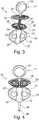
1 eine perspektivische Ansicht einer erfindungsgemäßen Positioniervorrichtung mit einer Gitterstruktur in einem ersten Ausführungsbeispiel und einer Mittellinienmarkierung,2 eine Seitenansicht der Positioniervorrichtung in dem ersten Ausführungsbeispiel der Gitterstruktur,3 eine perspektivische Ansicht einer für ein erfindungsgemäßes System eingesetzte Schädelbefestigungsvorrichtung mit einem Gegenabschnitt und einem Fixierelementabschnitt,4 eine perspektivische Ansicht der Schädelknochenbefestigungsvorrichtung mit dem Fixierelementabschnitt, der in den Gegenabschnitt eingeschraubt ist,5 eine perspektivische Ansicht des Gegenabschnitts mit einem Griffbereich und einem Abstützbereich,6 eine perspektivische Ansicht des Fixierelementabschnitts mit einem Griffbereich, einem Stützbereich und einem Koppelbereich, und7 die Schädelbefestigungsvorrichtung in einer perspektivischen Ansicht.
1 a perspective view of a positioning device according to the invention with a grid structure in a first embodiment and a center line marker,2 a side view of the positioning device in the first embodiment of the grid structure,3 a perspective view of a used for a system according to the invention skull attachment device with a counter portion and a Fixierelementabschnitt,4 3 is a perspective view of the skull bone fixation device with the fixation element section screwed into the mating section;5 a perspective view of the counter portion with a handle portion and a support area,6 a perspective view of the Fixierelementabschnitts with a handle portion, a support region and a coupling region, and7 the skull attachment device in a perspective view.
Die Figuren sind lediglich schematischer Natur und dienen ausschließlich dem Verständnis der Erfindung. Die gleichen Elemente sind mit denselben Bezugszeichen versehen.The figures are merely schematic in nature and are for the sole purpose of understanding the invention. The same elements are provided with the same reference numerals.
Die Tragstruktur
Die Stege
Von einer Vorderseite
Im Anschluss an die Aussparung
An der Vorderseite
Die Positioniervorrichtung
Der Gegenabschnitt
Die Verdickung
Der Abstützbereich
Der Abstützbereich
In den Gegenabschnitt
In
Mittig an dem Stützbereich
Der Gewindebereich
BezugszeichenlisteLIST OF REFERENCE NUMBERS
- 11
- Positioniervorrichtungpositioning
- 22
- Hauptkörpermain body
- 33
- Halteelementretaining element
- 44
- Randedge
- 55
- Tragstruktursupporting structure
- 66
- Stegweb
- 77
- Aussparung/DurchgangslochRecess / through hole
- 88th
- Wabenformhoneycomb
- 99
- HauptbegrenzungsflächeMain limiting surface
- 1010
- NebenbegrenzungsflächeBesides limiting surface
- 1111
- Vorderseitefront
- 1212
- Hinterseiteback
- 1313
- MittellinienmarkierungCentreline marking
- 1414
- Aussparungrecess
- 1515
- Schrägeslope
- 1616
- SchädelknochenbefestigungsvorrichtungSkull bone fixation device
- 1717
- FixierelementabschnittFixierelementabschnitt
- 1818
- Gegenabschnittcountersection
- 1919
- Griffbereichgrip area
- 2020
- Abstützbereichsupport area
- 2121
- Flügelwing
- 2222
- Verdickungthickening
- 2323
- Vertiefungdeepening
- 2424
- Aussparungrecess
- 2525
- DurchgangsbohrungThrough Hole
- 2626
- Konkave FlächeConcave surface
- 2727
- Konvexe FlächeConvex surface
- 2828
- Aussparungrecess
- 2929
- Stegweb
- 3030
- Innengewindeinner thread
- 3131
- Griffbereichgrip area
- 3232
- Stützbereichsupport area
- 3333
- Koppelbereichcoupling region
- 3434
- Gewindebereichthreaded portion
- 3535
- Endstiftend pin
- 3636
- Verdickungthickening
- 3737
- Vertiefungdeepening
- 3838
- Stegweb
- 3939
- Konkave FlächeConcave surface
- 4040
- Konvexe FlächeConvex surface
- 4141
- Stegweb
- 4242
- Aussparungrecess
- 4343
- SollbruchstelleBreaking point
ZITATE ENTHALTEN IN DER BESCHREIBUNG QUOTES INCLUDE IN THE DESCRIPTION
Diese Liste der vom Anmelder aufgeführten Dokumente wurde automatisiert erzeugt und ist ausschließlich zur besseren Information des Lesers aufgenommen. Die Liste ist nicht Bestandteil der deutschen Patent- bzw. Gebrauchsmusteranmeldung. Das DPMA übernimmt keinerlei Haftung für etwaige Fehler oder Auslassungen.This list of the documents listed by the applicant has been generated automatically and is included solely for the better information of the reader. The list is not part of the German patent or utility model application. The DPMA assumes no liability for any errors or omissions.
Zitierte PatentliteraturCited patent literature
- EP 2522289 A1 [0003]EP 2522289 A1 [0003]
Claims (10)
Translated fromGermanPriority Applications (10)
| Application Number | Priority Date | Filing Date | Title |
|---|---|---|---|
| DE102017107259.4ADE102017107259A1 (en) | 2017-04-04 | 2017-04-04 | Skull bone segment positioning device, positioning device manufacturing method and positioning device system with attachment devices |
| EP18716584.0AEP3606454B1 (en) | 2017-04-04 | 2018-04-04 | Positioning device for cranial bone sections, production method for positioning device and system comprising positioning device having fixing devices |
| PCT/EP2018/058636WO2018185179A1 (en) | 2017-04-04 | 2018-04-04 | Positioning device for cranial bone sections, production method for positioning device and system comprising positioning device having fixing devices |
| RU2019133569ARU2784171C2 (en) | 2017-04-04 | 2018-04-04 | Positioning device for skull bone sections, production method for positioning device, and system containing positioning device having fasteners |
| ES18716584TES2960339T3 (en) | 2017-04-04 | 2018-04-04 | Positioning device for cranial bone sections, manufacturing procedure for positioning device and system consisting of positioning device with fixation devices |
| BR112019020713-9ABR112019020713A2 (en) | 2017-04-04 | 2018-04-04 | POSITIONING DEVICE FOR CRANIAL BONE PORTIONS, MANUFACTURING METHOD FOR PRODUCTION OF A POSITIONING DEVICE, AND, SYSTEM. |
| AU2018247875AAU2018247875B2 (en) | 2017-04-04 | 2018-04-04 | Positioning device for cranial bone sections, production method for positioning device and system comprising positioning device having fixing devices |
| JP2019554908AJP7256750B2 (en) | 2017-04-04 | 2018-04-04 | System including positioning device with fastening device |
| CN201880023462.1ACN110740701B (en) | 2017-04-04 | 2018-04-04 | Skull part positioning device, method for manufacturing the same and system with fixing device thereof |
| US16/603,018US20200030014A1 (en) | 2017-04-04 | 2018-04-04 | Positioning device for cranial bone portions, production method for positioning device and system comprising positioning device having fastening devices |
Applications Claiming Priority (1)
| Application Number | Priority Date | Filing Date | Title |
|---|---|---|---|
| DE102017107259.4ADE102017107259A1 (en) | 2017-04-04 | 2017-04-04 | Skull bone segment positioning device, positioning device manufacturing method and positioning device system with attachment devices |
Publications (1)
| Publication Number | Publication Date |
|---|---|
| DE102017107259A1true DE102017107259A1 (en) | 2018-10-04 |
Family
ID=61913157
Family Applications (1)
| Application Number | Title | Priority Date | Filing Date |
|---|---|---|---|
| DE102017107259.4AWithdrawnDE102017107259A1 (en) | 2017-04-04 | 2017-04-04 | Skull bone segment positioning device, positioning device manufacturing method and positioning device system with attachment devices |
Country Status (9)
| Country | Link |
|---|---|
| US (1) | US20200030014A1 (en) |
| EP (1) | EP3606454B1 (en) |
| JP (1) | JP7256750B2 (en) |
| CN (1) | CN110740701B (en) |
| AU (1) | AU2018247875B2 (en) |
| BR (1) | BR112019020713A2 (en) |
| DE (1) | DE102017107259A1 (en) |
| ES (1) | ES2960339T3 (en) |
| WO (1) | WO2018185179A1 (en) |
Cited By (1)
| Publication number | Priority date | Publication date | Assignee | Title |
|---|---|---|---|---|
| DE102021202393A1 (en) | 2021-03-11 | 2022-09-15 | Karl Leibinger Medizintechnik Gmbh & Co. Kg | OPTIMIZED IMPLANT SYSTEM |
Families Citing this family (1)
| Publication number | Priority date | Publication date | Assignee | Title |
|---|---|---|---|---|
| US20250072847A1 (en)* | 2023-09-01 | 2025-03-06 | Adaptiiv Medical Technologies Inc. | Immobilization devices for radiation therapy |
Citations (3)
| Publication number | Priority date | Publication date | Assignee | Title |
|---|---|---|---|---|
| US20020169455A1 (en)* | 2001-02-23 | 2002-11-14 | Brett Bannerman | System and method for fixation of cranial flaps |
| EP2522289A1 (en) | 2004-04-23 | 2012-11-14 | IBB Technologie-Entwicklungs-Fonds GmbH & Co. KG (TEF). | Three-dimensional life size model of a human child's skull and method using the model |
| US20150265448A1 (en)* | 2012-11-09 | 2015-09-24 | Ernst-Johannes HABERL | System for reshaping skull |
Family Cites Families (13)
| Publication number | Priority date | Publication date | Assignee | Title |
|---|---|---|---|---|
| US6685707B2 (en)* | 2001-09-25 | 2004-02-03 | Walter Lorenz Surgical, Inc. | Cranial clamp and method for fixating a bone plate |
| US7387633B2 (en)* | 2003-04-04 | 2008-06-17 | Osteomed L.P. | Cranial flap fixation system and method |
| JP4041788B2 (en)* | 2003-10-31 | 2008-01-30 | ケイセイ医科工業株式会社 | Skull treatment device |
| US7833253B2 (en)* | 2006-01-17 | 2010-11-16 | Biodynamics Llc | Craniotomy closures and plugs |
| JP5751642B2 (en)* | 2009-09-04 | 2015-07-22 | エリプス テクノロジーズ, インク.Ellipse Technologies, Inc. | Bone growth apparatus and method |
| US8867804B2 (en)* | 2010-11-08 | 2014-10-21 | Cranial Technologies, Inc. | Method and apparatus for automatically generating trim lines for cranial remodeling devices |
| WO2013036582A1 (en)* | 2011-09-06 | 2013-03-14 | Skeletal Dynamics, L.L.C. | Fracture fixation plate, system and methods of use |
| EP2792333B1 (en)* | 2011-12-14 | 2015-11-25 | Industrias Médicas Sampedro S.A. | Cost-effective method for manufacturing metal cranial prostheses |
| WO2013155043A1 (en)* | 2012-04-09 | 2013-10-17 | The Johns Hopkins University | Universal cranioplasty mesh |
| WO2014110421A1 (en)* | 2013-01-11 | 2014-07-17 | The Uab Research Foundation | Apparatus for the fixation of proximal humerus fractures |
| US9220597B2 (en)* | 2013-02-12 | 2015-12-29 | Ossdsign Ab | Mosaic implants, kits and methods for correcting bone defects |
| ES2983663T3 (en)* | 2013-12-09 | 2024-10-24 | Lima Usa Inc | Surgical navigation system |
| RU2638894C2 (en)* | 2016-06-03 | 2017-12-18 | Общество с ограниченной ответственностью "КОНМЕТ" | Implant for cranial bones prosthetics and method of implant manufacture for cranial bones prosthetics |
- 2017
- 2017-04-04DEDE102017107259.4Apatent/DE102017107259A1/ennot_activeWithdrawn
- 2018
- 2018-04-04ESES18716584Tpatent/ES2960339T3/enactiveActive
- 2018-04-04AUAU2018247875Apatent/AU2018247875B2/ennot_activeCeased
- 2018-04-04JPJP2019554908Apatent/JP7256750B2/enactiveActive
- 2018-04-04USUS16/603,018patent/US20200030014A1/ennot_activeAbandoned
- 2018-04-04EPEP18716584.0Apatent/EP3606454B1/enactiveActive
- 2018-04-04BRBR112019020713-9Apatent/BR112019020713A2/enactiveSearch and Examination
- 2018-04-04CNCN201880023462.1Apatent/CN110740701B/ennot_activeExpired - Fee Related
- 2018-04-04WOPCT/EP2018/058636patent/WO2018185179A1/ennot_activeCeased
Patent Citations (3)
| Publication number | Priority date | Publication date | Assignee | Title |
|---|---|---|---|---|
| US20020169455A1 (en)* | 2001-02-23 | 2002-11-14 | Brett Bannerman | System and method for fixation of cranial flaps |
| EP2522289A1 (en) | 2004-04-23 | 2012-11-14 | IBB Technologie-Entwicklungs-Fonds GmbH & Co. KG (TEF). | Three-dimensional life size model of a human child's skull and method using the model |
| US20150265448A1 (en)* | 2012-11-09 | 2015-09-24 | Ernst-Johannes HABERL | System for reshaping skull |
Cited By (1)
| Publication number | Priority date | Publication date | Assignee | Title |
|---|---|---|---|---|
| DE102021202393A1 (en) | 2021-03-11 | 2022-09-15 | Karl Leibinger Medizintechnik Gmbh & Co. Kg | OPTIMIZED IMPLANT SYSTEM |
Also Published As
| Publication number | Publication date |
|---|---|
| EP3606454A1 (en) | 2020-02-12 |
| JP2020512889A (en) | 2020-04-30 |
| AU2018247875A1 (en) | 2019-10-31 |
| AU2018247875B2 (en) | 2023-09-21 |
| JP7256750B2 (en) | 2023-04-12 |
| US20200030014A1 (en) | 2020-01-30 |
| ES2960339T3 (en) | 2024-03-04 |
| EP3606454B1 (en) | 2023-08-16 |
| WO2018185179A1 (en) | 2018-10-11 |
| RU2019133569A (en) | 2021-04-22 |
| BR112019020713A2 (en) | 2020-05-12 |
| RU2019133569A3 (en) | 2021-07-15 |
| CN110740701A (en) | 2020-01-31 |
| CN110740701B (en) | 2022-11-29 |
Similar Documents
| Publication | Publication Date | Title |
|---|---|---|
| DE69737034T2 (en) | MODULAR CONSTRUCTED, MULTIPLE PEDICELIC SCREW WITH LOCK | |
| DE60209732T2 (en) | SYSTEM FOR OSTEOSYNTHESIS ON THE SPINE AND METHOD FOR THE PRODUCTION THEREOF | |
| EP2030596B1 (en) | Implant for treating bones. | |
| EP3122290B1 (en) | Eye socket covering grid with longitudinal recesses following external contours | |
| WO2001019268A1 (en) | Fixation system for bones | |
| DE202005019277U1 (en) | Bone plate for adjustable securing broken bone together for healing has two or more holes (16) lengthened along the long axis of the plate and two or more holes lengthed at right angles to theplate long axis | |
| DE8915443U1 (en) | Implant for a spinal osteosynthesis device, especially in traumatology | |
| EP3393376B1 (en) | Implant for reinforcing a bone, comprising a bore vector specifying hole and surrounding plate for a jaw replacement, and implant production method | |
| DE112016003552T5 (en) | Medical device for surgical correction of funnel chest deformity | |
| DE102016105230A1 (en) | Stabilizing structure for the stabilization or fixation of sternoclavicular joints | |
| EP3606454B1 (en) | Positioning device for cranial bone sections, production method for positioning device and system comprising positioning device having fixing devices | |
| DE602005000522T2 (en) | Implants for a device for spinal osteosynthesis and placement with these implants | |
| DE102012002552A1 (en) | orthosis | |
| EP3616636B1 (en) | Bone plate and surgical sets | |
| DE202007002190U1 (en) | Part cylindrical Hallux-Valgus bone plate has through holes for bone screws on different angle axes and cylindrical curvature varying in longitudinal direction | |
| EP1364621B1 (en) | Device for positioning and fixing bone and/or bone fragments | |
| DE202014004751U1 (en) | implant | |
| DE102017102236A1 (en) | Supporting element for a distractor arrangement | |
| EP3755252A1 (en) | Wrist arthrodesis plate and method using a wrist arthrodesis plate | |
| DE20203174U1 (en) | Device for stabilizing invoices | |
| RU2784171C2 (en) | Positioning device for skull bone sections, production method for positioning device, and system containing positioning device having fasteners | |
| DE202025001907U1 (en) | Device for the osteosynthetic treatment of bone fractures, especially patella fractures | |
| CH721505A1 (en) | Device for the osteosynthetic treatment of bone fractures, especially patella fractures | |
| DE102017107261A1 (en) | A skull bone fixation device for attaching a cranial bone portion to a positioning device | |
| DE20109273U1 (en) | Device for stabilizing fractures |
Legal Events
| Date | Code | Title | Description |
|---|---|---|---|
| R163 | Identified publications notified | ||
| R005 | Application deemed withdrawn due to failure to request examination |