DE102017104627A1 - POSITIONING AID FOR TMS - Google Patents
POSITIONING AID FOR TMSDownload PDFInfo
- Publication number
- DE102017104627A1 DE102017104627A1DE102017104627.5ADE102017104627ADE102017104627A1DE 102017104627 A1DE102017104627 A1DE 102017104627A1DE 102017104627 ADE102017104627 ADE 102017104627ADE 102017104627 A1DE102017104627 A1DE 102017104627A1
- Authority
- DE
- Germany
- Prior art keywords
- head
- support
- patient
- head unit
- unit
- Prior art date
- Legal status (The legal status is an assumption and is not a legal conclusion. Google has not performed a legal analysis and makes no representation as to the accuracy of the status listed.)
- Pending
Links
- 230000033001locomotionEffects0.000claimsabstractdescription69
- 230000008859changeEffects0.000claimsabstractdescription19
- 238000011491transcranial magnetic stimulationMethods0.000claimsabstractdescription11
- 230000008878couplingEffects0.000claimsdescription66
- 238000010168coupling processMethods0.000claimsdescription66
- 238000005859coupling reactionMethods0.000claimsdescription66
- 238000013519translationMethods0.000claimsdescription20
- 238000000034methodMethods0.000claimsdescription18
- 238000011282treatmentMethods0.000claimsdescription12
- 238000006073displacement reactionMethods0.000claimsdescription7
- 230000009467reductionEffects0.000claimsdescription3
- 210000003128headAnatomy0.000description269
- 230000000638stimulationEffects0.000description22
- 210000004556brainAnatomy0.000description6
- 238000002560therapeutic procedureMethods0.000description4
- 210000000988bone and boneAnatomy0.000description3
- 230000004886head movementEffects0.000description3
- 238000005259measurementMethods0.000description3
- 230000005540biological transmissionEffects0.000description2
- 238000006243chemical reactionMethods0.000description2
- 238000011161developmentMethods0.000description2
- 230000018109developmental processEffects0.000description2
- 238000009434installationMethods0.000description2
- BUHVIAUBTBOHAG-FOYDDCNASA-N(2r,3r,4s,5r)-2-[6-[[2-(3,5-dimethoxyphenyl)-2-(2-methylphenyl)ethyl]amino]purin-9-yl]-5-(hydroxymethyl)oxolane-3,4-diolChemical compoundCOC1=CC(OC)=CC(C(CNC=2C=3N=CN(C=3N=CN=2)[C@H]2[C@@H]([C@H](O)[C@@H](CO)O2)O)C=2C(=CC=CC=2)C)=C1BUHVIAUBTBOHAG-FOYDDCNASA-N0.000description1
- 206010010904ConvulsionDiseases0.000description1
- 206010019233HeadachesDiseases0.000description1
- 241000746998TragusSpecies0.000description1
- 230000009471actionEffects0.000description1
- 238000013459approachMethods0.000description1
- 238000013528artificial neural networkMethods0.000description1
- 230000000295complement effectEffects0.000description1
- 238000013016dampingMethods0.000description1
- 230000007423decreaseEffects0.000description1
- 230000001419dependent effectEffects0.000description1
- 230000001066destructive effectEffects0.000description1
- 210000005069earsAnatomy0.000description1
- 230000000694effectsEffects0.000description1
- 230000005672electromagnetic fieldEffects0.000description1
- 238000005516engineering processMethods0.000description1
- 206010015037epilepsyDiseases0.000description1
- 208000028329epileptic seizureDiseases0.000description1
- 230000005284excitationEffects0.000description1
- 210000003811fingerAnatomy0.000description1
- 210000001061foreheadAnatomy0.000description1
- 231100000869headacheToxicity0.000description1
- 230000006872improvementEffects0.000description1
- 230000005764inhibitory processEffects0.000description1
- 238000002595magnetic resonance imagingMethods0.000description1
- 230000007659motor functionEffects0.000description1
- 238000011369optimal treatmentMethods0.000description1
- 230000002028prematureEffects0.000description1
- 230000002035prolonged effectEffects0.000description1
- 238000011160researchMethods0.000description1
- 210000003625skullAnatomy0.000description1
- 230000001360synchronised effectEffects0.000description1
- 230000001225therapeutic effectEffects0.000description1
- 230000008719thickeningEffects0.000description1
- 210000003813thumbAnatomy0.000description1
- 238000012549trainingMethods0.000description1
- 238000012546transferMethods0.000description1
- 238000002604ultrasonographyMethods0.000description1
Images


Classifications
- A—HUMAN NECESSITIES
- A61—MEDICAL OR VETERINARY SCIENCE; HYGIENE
- A61N—ELECTROTHERAPY; MAGNETOTHERAPY; RADIATION THERAPY; ULTRASOUND THERAPY
- A61N2/00—Magnetotherapy
- A61N2/004—Magnetotherapy specially adapted for a specific therapy
- A61N2/006—Magnetotherapy specially adapted for a specific therapy for magnetic stimulation of nerve tissue
- A—HUMAN NECESSITIES
- A61—MEDICAL OR VETERINARY SCIENCE; HYGIENE
- A61N—ELECTROTHERAPY; MAGNETOTHERAPY; RADIATION THERAPY; ULTRASOUND THERAPY
- A61N2/00—Magnetotherapy
- A61N2/02—Magnetotherapy using magnetic fields produced by coils, including single turn loops or electromagnets
Landscapes
- Health & Medical Sciences (AREA)
- Engineering & Computer Science (AREA)
- Biomedical Technology (AREA)
- Nuclear Medicine, Radiotherapy & Molecular Imaging (AREA)
- Radiology & Medical Imaging (AREA)
- Life Sciences & Earth Sciences (AREA)
- Animal Behavior & Ethology (AREA)
- General Health & Medical Sciences (AREA)
- Public Health (AREA)
- Veterinary Medicine (AREA)
- Neurology (AREA)
- Magnetic Treatment Devices (AREA)
Abstract
Translated fromGermanDescription
Translated fromGermanDie vorliegende Erfindung betrifft eine Vorrichtung zum Positionieren einer Magnetspule relativ zum Kopf eines Patienten sowie ein Verfahren zum Positionieren einer Magnetspule relativ zum Kopf eines Patienten.The present invention relates to a device for positioning a magnetic coil relative to the head of a patient and to a method for positioning a magnetic coil relative to the head of a patient.
Die transkranielle Magnetstimulation (TMS) ist ein nicht-invasives Verfahren zur Erregung oder Inhibition neuronaler Netzwerke im Gehirn. Neben der Gehirnforschung wird sie auch zur therapeutischen Behandlung z. B. von Depression eingesetzt.Transcranial magnetic stimulation (TMS) is a non-invasive method of excitation or inhibition of neural networks in the brain. In addition to brain research, it is also used for therapeutic treatment z. B. used by depression.
Die korrekte und reproduzierbare Positionierung einer dabei verwendeten Magnetspule am Kopf des Patienten ist bei der TMS eine der wichtigsten Anforderungen. Dabei müssen für jeden Patienten individuelle Stimulationspunkte, sogenannte Hot-Spots, gesucht und bei jeder Sitzung wiedergefunden werden. Die Stimulationsspule muss am gewünschten Stimulationspunkt positioniert werden und muss während einer Sitzung durchgehend an dieser Position verbleiben. Zur Entlastung des Patientennackens während den Sitzungen wird entweder ein Vakuumkissen zur entspannten Lagerung des Kopfes oder ein Patientensessel mit integrierter Kopfauflage verwendet.The correct and reproducible positioning of a magnetic coil used on the patient's head is one of the most important requirements of the TMS. In this case, individual stimulation points, so-called hot spots, must be searched for each patient and found again at each session. The stimulation coil must be positioned at the desired stimulation point and must remain in that position throughout a session. To relieve the patient's neck during the sessions, either a vacuum pad for relaxed storage of the head or a patient chair with integrated headrest is used.
Im klinischen Alltag werden meist Kappen oder Badehauben für den Kopf verwendet, auf denen die individuellen Stimulationspunkte eines Patienten markiert werden. Zur Bestimmung eines geeigneten Stimulationsortes und einer geeigneten Stimulationsintensität wird der Kopf vermessen und mögliche Stimulationspunkte (sogenanntes 9-Punkte-Grid) werden eingezeichnet. Danach wird auf Basis des eingezeichneten Grids durch Abgabe von Stimulationspulsen in ausreichender Intensität und entsprechender Orientierung der Spule das Gehirnareal gesucht, welches die Handmotorik im Gehirn repräsentiert. Bei Stimulation des richtigen Ortes mit ausreichender Intensität wird die Reaktion des Daumens gemessen. Der Punkt mit der besten Reaktion wird auf der Haube markiert. Die individuelle Stimulationsstärke wird hier gemessen, und außerdem dient dieser Punkt als Ausgangspunkt für die Vermessung und Markierung des individuellen Therapiepunktes (z.B. über die 5 cm Regel). Dieser individuell vermessene Therapiepunkt wird auf der Kappe markiert und wird für jede Sitzung als Stimulationsort verwendet. Die Position der Spule muss während der Behandlung durch Halten der Spule oder durch Einspannen in eine Haltevorrichtung sichergestellt werden. Eine Fixierung bzw. Unterstützung des Kopfes wird hierbei nicht berücksichtigt und kann separat z.B. über ein Vakuumkissen oder eine entsprechende Nackenstütze am Patientensessel realisiert werden. Diese Methode stellt eine sehr einfach zu erlernende und kostengünstige Lösung dar. Allerdings können die Stimulationspunkte nie zu 100% genau wiedergefunden werden, da die Kappe nie ein zweites Mal exakt gleich aufgesetzt werden kann. Außerdem darf sich der Kopf des Patienten während der Stimulation nicht bewegen und die Spule muss so gehalten werden, dass sie die Position am Kopf für die Dauer der Stimulation nicht verändert.In clinical practice, caps or bath caps are usually used for the head, on which the individual stimulation points of a patient are marked. To determine a suitable stimulation site and a suitable stimulation intensity, the head is measured and possible stimulation points (so-called 9-point grid) are drawn. Then, on the basis of the indicated grid, the brain area which represents the hand motor function in the brain is searched by emitting stimulation pulses of sufficient intensity and corresponding orientation of the coil. When the right place is stimulated with sufficient intensity, the reaction of the thumb is measured. The point with the best reaction is marked on the hood. The individual stimulation intensity is measured here, and this point also serves as a starting point for the measurement and marking of the individual therapy point (for example, over the 5 cm rule). This individually measured therapy point is marked on the cap and used as stimulation site for each session. The position of the coil must be ensured during treatment by holding the coil or by clamping in a holding device. A fixation or support of the head is not taken into account in this case and can be done separately e.g. be realized on a vacuum cushion or a corresponding neck support on the patient chair. This method is a very easy-to-learn and cost-effective solution. However, the stimulation points can never be recovered to 100% accuracy, as the cap can never be placed exactly the same way a second time. In addition, the patient's head should not move during pacing and the coil must be held so that it does not change the position on the head for the duration of the stimulation.
Außerdem bekannt ist die Verwendung von Spulenpositionierungssystemen, bei denen die Spule auf Basis von Halte- und Messwerkzeugen individuell relativ zum Kopf positioniert wird. Bei diesen Systemen darf der Patient während der Stimulation die Lage des Kopfes nicht verändern, da die Spulenpositionierungssysteme der Bewegung des Kopfes nicht folgen können bzw. der Kontakt der Spule zum Kopf per Sensor gemessen wird und es zum Abbruch der Stimulation führt, wenn die Spule den Kontakt zum Kopf verliert (z.B. durch eine Kopfbewegung). Des Weiteren muss bei der Verwendung dieser Methode ein spezieller Patientensessel eigesetzt werden, der den Kopf des Patienten während der Stimulation stützt.Also known is the use of coil positioning systems in which the coil is individually positioned relative to the head based on holding and measuring tools. In these systems, the patient must not change the position of the head during the stimulation, since the coil positioning systems can not follow the movement of the head or the contact of the coil to the head is measured by the sensor and it leads to the termination of the stimulation, when the coil Contact to the head loses (eg by a head movement). Furthermore, when using this method, a special patient chair must be used that supports the patient's head during stimulation.
Zur hochpräzisen Positionierung der Spule können Neuronavigationssysteme eingesetzt werden. Diese verwenden MRT-Aufnahmen des jeweiligen Patienten um ein dreidimensionales Modell des Kopfes und des Gehirns zu erstellen. Mit Hilfe von Ultraschall- oder Infrarot-Trackingsystemen werden die Positionen von Spule und Kopf/Gehirn relativ zueinander in Echtzeit bestimmt und im 3D-Modell dargestellt. Hiermit kann die Spule sehr einfach über dem zu stimulierende Areal positioniert und die Position der Spule abgespeichert werden. Obwohl das Finden des richtigen Stimulationsortes durch die Neuronavigation nicht unbedingt erleichtert wird (der Therapiepunkt muss wie bei der Verwendung der Kappen händisch vermessen werden), bietet diese Methodik durch diverse Speichermöglichkeiten der Spulen-Kopf-Koordinaten eine sehr gute Reproduzierbarkeit und Dokumentationsmöglichkeit des Stimulationsortes sobald dieser bestimmt ist. Allerdings müssen auch bei dieser Methode sowohl die von Hand oder über ein Haltesystem gehaltene Spule als auch der Kopf des Patienten über die gesamte Stimulationsdauer ruhig gehalten werden, da ansonsten die Stimulationsposition verlassen wird. Außerdem sind die Kosten für die Anschaffung eines solchen Systems sind sehr hoch. Des Weiteren muss der Anwender im Umgang mit Computer, Software und Navigationssystemen geschult sein.For high-precision positioning of the coil, neuronavigation systems can be used. These use MRI scans of each patient to create a three-dimensional model of the head and brain. With the help of ultrasound or infrared tracking systems, the positions of coil and head / brain are determined relative to each other in real time and displayed in the 3D model. This allows the coil to be easily positioned over the area to be stimulated and the position of the coil to be stored. Although neuronavigation does not necessarily make it easier to find the right stimulation site (the therapy point has to be measured manually, as with the use of caps), this method offers a very good reproducibility and documentation of the stimulation site as soon as this is possible thanks to various storage possibilities of the coil-head coordinates is determined. However, even with this method, both the coil held by hand or a holding system and the patient's head must be kept still throughout the stimulation period, otherwise the stimulation position will be left. Besides, the cost of purchasing such a system are very high. Furthermore, the user must be trained in handling computers, software and navigation systems.
Eine relativ neue Entwicklung ist ein TMS-Roboter als Art intelligenter Spulenhalter, der mit Hilfe eines Neuronavigationssystems die Spule automatisch an der in der Navigation markierten Position relativ zum Kopf des Patienten hält und sie bei einer Bewegung des Patienten nachführt. Der TMS-Roboter kann die Spule in drei oder mehr Richtungen bewegen und in Verbindung mit einem Sensor so die entsprechende Positionierung und den Kontakt der Spule zum Kopf sicherstellen. Nachteilig ist der große Platz-, Technologie- und Schulungsbedarf, um den teuren Roboter zu bedienen.A relatively recent development is a TMS robot as a kind of intelligent bobbin holder, which automatically holds the bobbin relative to the head of the patient using a neuronavigation system at the position marked in the navigation and tracks it as the patient moves. The TMS robot can move the coil in three or more directions and in conjunction with a sensor so Ensure appropriate positioning and contact of the coil with the head. The disadvantage is the large space, technology and training needs to operate the expensive robot.
Aus der
Weitere Positionierungssysteme zur transkraniellen Magnetstimulation sind aus der
Es ist Aufgabe der Erfindung, eine Vorrichtung zum Positionieren einer Magnetspule relativ zum Kopf eines Patienten sowie ein entsprechendes Positionierungsverfahren bereitzustellen, die bei dem Patienten auch bei längerer Haltedauer der Magnetspule möglichst kein oder wenig Unbehagen hervorrufen.It is an object of the invention to provide a device for positioning a magnetic coil relative to the head of a patient and a corresponding positioning method, which cause as little or no discomfort in the patient even with prolonged holding time of the solenoid.
Diese Aufgabe wird bezüglich der Vorrichtung durch den Gegenstand von Anspruch 1, bezüglich des Verfahrens durch den Gegenstand von Anspruch 17 gelöst. Die abhängigen Ansprüche geben vorteilhafte Weiterbildungen der Erfindung an.This object is achieved with respect to the apparatus by the subject-matter of
Erfindungsgemäß wird eine Vorrichtung zum Positionieren einer Magnetspule zur transkraniellen Magnetstimulation relativ zum Kopf eines Patienten bereitgestellt. Die Vorrichtung umfasst eine Kopfeinheit mit einer Stützauflage für den Kopf des Patienten und mit einer mit der Stützauflage verbundenen Positioniereinheit. Die Positioniereinheit umfasst eine Spulenaufnahme zum Halten der Magnetspule. Zudem umfasst die Vorrichtung einen raumfest installierbaren Haltearm, der die Kopfeinheit hält.According to the invention, a device is provided for positioning a magnetic coil for transcranial magnetic stimulation relative to the head of a patient. The device comprises a head unit with a support support for the head of the patient and with a positioning unit connected to the support support. The positioning unit comprises a coil receptacle for holding the magnetic coil. In addition, the device comprises a space fixed installable arm, which holds the head unit.
Der Haltearm kann beispielsweise an oder zumindest relativ zu einem Boden oder einer Wand eines Behandlungsraums oder einem Patientensessel raumfest befestigt werden. Es ist auch denkbar, den Haltearm an einem Gerätewagen anzubringen. „Raumfest installierbar“ soll bezüglich des Haltearms heißen, dass seine Position und Ausrichtung nach der Installation zumindest soweit festgelegt ist, als dass er durch typische Bewegungen des Kopfes des Patienten, welche über die Stützauflage und die Kopfeinheit auf ihn einwirken, nicht bewegt oder verstellt wird. Vorzugsweise lässt sich der Haltearm wahlweise in einen Einstellmodus und in einen installierten Modus verbringen. In dem Einstellmodus kann der Haltearm zur geeigneten Positionierung in Bezug auf den Patienten mittels einer oder mehrerer Verstellmöglichkeiten verstellt werden. Beispielsweise ist eine Höhenverstellbarkeit durch teleskopisch ineinander gesteckte Teilelemente des Haltearms denkbar, um den Haltearm an eine Größe des Patienten anzupassen. Alternativ oder zusätzlich können mehrere Teilsegmente des Haltearms in dem Einstellmodus relativ zueinander verschwenkbar sein. Von dem Einstellmodus kann der Haltearm beispielsweise durch Arretieren der teleskopisch ineinander gesteckten Teilelemente im Bezug aufeinander und/oder durch Arretieren der Schwenkverbindungen seiner Teilsegmente in den installierten Modus verbracht werden, so dass der Haltearm raumfest installiert ist.The holding arm can for example be fastened fixed to space or at least relative to a floor or a wall of a treatment room or a patient chair. It is also conceivable to attach the support arm to a trolley. "Installable in space" with respect to the support arm means that its position and orientation after installation is set at least as far as it is not moved or displaced by typical movements of the patient's head, which act on him via the support support and the head unit , Preferably, the support arm can be selectively spent in a setting mode and in an installed mode. In the adjustment mode, the support arm can be adjusted for proper positioning with respect to the patient by means of one or more adjustments. For example, a height adjustment by telescopically nested sub-elements of the support arm is conceivable to adapt the support arm to a size of the patient. Alternatively or additionally, a plurality of sub-segments of the support arm in the adjustment mode can be pivoted relative to each other. From the adjustment mode of the support arm can be spent, for example, by locking the telescopically nested sub-elements with respect to each other and / or by locking the pivotal connections of its sub-segments in the installed mode, so that the support arm is installed fixed in space.
Erfindungsgemäß ist zwischen der Kopfeinheit und dem Haltearm eine bewegliche Verbindung vorgesehen. Die bewegliche Verbindung ist so ausgestaltet, dass eine Änderung einer durch den Kopf des Patienten auf die Stützauflage ausgeübten Kraft über die bewegliche Verbindung eine Relativbewegung zwischen der Kopfeinheit und dem Haltearm bewirkt. Die Verbindung zwischen der Kopfeinheit und dem Haltearm ist reversibel beweglich. Das heißt, dass eine von einer Änderung der durch den Kopf des Patienten auf die Stützauflage ausgeübten Kraft bewirkte Relativbewegung zwischen der Kopfeinheit und dem Haltearm rückgängig gemacht werden kann (im Gegensatz zu beispielsweise einer ratschenartigen Beweglichkeit). Es versteht sich, dass im Sinne der Erfindung die Relativbewegung zwischen der Kopfeinheit und dem Haltearm zerstörungsfrei erfolgen soll.According to the invention, a movable connection is provided between the head unit and the holding arm. The movable connection is configured such that a change in a force exerted by the patient's head on the support pad over the movable connection causes a relative movement between the head unit and the support arm. The connection between the head unit and the holding arm is reversibly movable. That is, a relative movement between the head unit and the holding arm caused by a change in the force exerted by the head of the patient on the support pad can be reversed (as opposed to, for example, a ratchet-like mobility). It is understood that for the purposes of the invention, the relative movement between the head unit and the support arm should be destructive.
Die von dem Haltearm gehaltene Stützauflage übernimmt zumindest einen Teil des Gewichts des Kopfes und ermöglicht so eine komfortable und entspannte Lagerung des Kopfes auch über einen längeren Zeitraum hinweg. Da die Kopfeinheit von dem Haltearm gehalten wird, muss nicht das gesamte Gewicht der Kopfeinheit sowie einer daran befestigten Magnetspule von dem Kopf des Patienten getragen werden. Auch dies wirkt sich vorteilhaft auf eine entspannte Lagerung des Kopfes aus. Vorzugsweise ist das System selbsttragend.The support support held by the support arm takes over at least part of the weight of the head and thus allows a comfortable and relaxed storage of the head over a longer period of time. Since the head unit is held by the support arm, it is not necessary to support the entire weight of the head unit and a solenoid attached thereto from the head of the patient. This also has an advantageous effect on a relaxed storage of the head. Preferably, the system is self-supporting.
Aufgrund der beweglichen Verbindung zwischen Kopfeinheit und Haltearm kann die Kopfeinheit auf eine Änderung der Kopfposition des Patienten oder auf eine Änderung einer Andrück- oder Auflagekraft des Kopfes auf die Stützauflage mit einer Relativbewegung in Bezug auf den Haltearm reagieren. Somit ist ein raumfestes Fixieren des Kopfes nicht mehr notwendig und der Patient hat jederzeit die Möglichkeit, selbst die Vorrichtung zu verlassen. Dies führt unter anderem dazu, dass der Patient die erfindungsgemäße Vorrichtung als besonders vertrauenserweckend aufnimmt. Zudem wird das Notfallprozedere bei einem epileptischen Anfall des Patienten oder Ähnlichem vereinfacht.Due to the movable connection between the head unit and the support arm, the head unit can respond to a change in the head position of the patient or to a change of a pressing or bearing force of the head on the support support with a relative movement with respect to the support arm. Thus, a spatially fixed fixing of the head is no longer necessary and the patient has always the opportunity to leave even the device. Among other things, this leads to the patient receiving the device according to the invention as a particularly confidence-inspiring one. In addition, the emergency procedure is simplified in an epileptic seizure of the patient or the like.
Vorzugsweise ist die bewegliche Verbindung zwischen der Kopfeinheit und dem Halteelement als permanent bewegliche Verbindung ausgebildet. Das kann heißen, dass die bewegliche Verbindung unverriegelbar ist und/oder keine Einrastposition aufweist. Hierdurch wird gewährleistet, dass sich die Position der Kopfeinheit unabhängig vom momentanen Betriebszustand an die von dem Kopf des Patienten auf die Stützauflage ausgeübte Kraft anpasst.Preferably, the movable connection between the head unit and the holding element is designed as a permanently movable connection. This may mean that the movable connection is unlockable and / or has no latching position. This ensures that the position of the head unit adapts to the force exerted by the head of the patient on the support pad regardless of the current operating condition.
Die Positioniereinheit kann starr oder starr fixierbar mit der Stützauflage verbunden sein. So kann eine optimale Kraftübertragung zwischen der Stützauflage und dem Rest der Kopfeinheit erreicht werden. Insbesondere wird die von dem Kopf des Patienten auf die Stützauflage ausgeübte Kraft direkt an die Positioniereinheit mit der daran angebrachten Spule übertragen. Besonders bevorzugt ist es, wenn die Positioniereinheit in einem Einstellmodus gegenüber der Stützauflage verschiebbar ist und so an den Kopf des Patienten angepasst werden kann. Nach der Anpassung kann die Relativposition zwischen Positioniereinheit und Stützauflage mit einem Feststellelement festgelegt werden, so dass zwischen der Positioniereinheit und der Stützauflage eine starre Verbindung vorliegt.The positioning unit can be rigidly or rigidly connected to the support pad. Thus, an optimal power transmission between the support pad and the rest of the head unit can be achieved. In particular, the force exerted by the patient's head on the support pad is transmitted directly to the positioning unit with the coil attached thereto. It is particularly preferred if the positioning unit is displaceable in a setting mode relative to the support support and can thus be adapted to the head of the patient. After the adjustment, the relative position between the positioning unit and the support surface can be fixed with a locking element, so that there is a rigid connection between the positioning unit and the support surface.
Vorzugsweise ist die Stützauflage so ausgelegt, dass eine Änderung der durch den Kopf des Patienten auf die Stützauflage ausgeübten Kraft und/oder eine Bewegung des durch die Stützauflage gestützten Kopfes ein Mitführen der Kopfeinheit mit einer Bewegung des Kopfes bewirkt. Beispielsweise kann ein Drehen des Kopfes nach links oder rechts eine derartige Änderung der durch den Kopf auf die Stützauflage ausgeübten Kraft bewirken, dass sich die Kopfeinheit über die bewegliche Verbindung ebenfalls nach links oder rechts dreht, dem Kopf also folgt. Dabei kann die Relativposition zwischen der von der Spulenaufnahme gehaltenen Magnetspule und dem Kopf des Patienten zumindest im Wesentlichen konstant bleiben. Zumindest kann durch das Mitführen der Kopfeinheit eine Größe der Lageverschiebung zwischen Kopf und Magnetspule bei einer Bewegung des Kopfes abgeschwächt werden. Der Patient kann seinen Kopf also innerhalb eines gewissen Maßes bewegen, ohne dass die Position der Magnetspule neu eingestellt werden muss.Preferably, the support pad is designed so that a change in the force exerted by the head of the patient on the support pad force and / or movement of the supported by the support pad head causes the head unit with a movement of the head. For example, turning the head to the left or right may cause such a change in the force exerted by the head on the support pad that the head unit will also turn left or right over the movable link, thus following the head. In this case, the relative position between the solenoid coil held by the coil holder and the head of the patient can remain at least substantially constant. At least can be mitigated by the entrainment of the head unit, a size of the positional shift between the head and solenoid during a movement of the head. The patient can thus move his head to a certain extent without having to readjust the position of the magnetic coil.
Vorzugsweise bleibt bei der Relativbewegung zwischen der Kopfeinheit und dem Haltearm über die bewegliche Verbindung die Lage der Spulenaufnahme relativ zu der Stützauflage gleich. So wird gewährleistet, dass die in der Spulenaufnahme gehaltene Magnetspule ihre Position relativ zu dem von der Stützauflage gestützten Kopf zumindest im Wesentlichen nicht ändert.Preferably, in the relative movement between the head unit and the holding arm via the movable connection, the position of the coil receiving relative to the support support remains the same. This ensures that the magnetic coil held in the coil holder at least substantially does not change its position relative to the head supported by the supporting support.
Die bewegliche Verbindung zwischen der Kopfeinheit und dem Haltearm kann gemäß einer bevorzugten Ausführungsform der durch den Kopf des Patienten auf die Stützauflage ausgeübten Kraft federnd entgegenwirken. Durch die federnde Gegenkraft erfährt der Kopf des Patienten eine optimale und an die Kopfposition und die jeweilige Auflagekraft des Kopfes angepasste Unterstützung. Wird durch den Kopf des Patienten eine erhöhte Kraft auf die Stützauflage ausgeübt, kann sich diese relativ zu dem Haltearm entgegen der Federwirkung bewegen. Hierdurch kann eine Rückstellkraft in die vorausgegangene Position entstehen, so dass bei einer erneuten Reduktion der durch den Kopf auf die Stützauflage ausgeübten Kraft die Kopfeinheit durch die Rückstellkraft in die vorangegangene Position bewegt wird. Zudem erfährt ein von dem Kopf des Patienten auf die Stützauflage ruckartig aufgebrachter Kraftimpuls eine Dämpfung, so dass keine ruckartigen Bewegungen der Kopfeinheit erfolgen.The movable connection between the head unit and the support arm can, according to a preferred embodiment, resiliently counteract the force exerted by the patient's head on the support support. Due to the resilient counterforce, the patient's head experiences optimum support adapted to the head position and the respective bearing force of the head. If an increased force exerted by the head of the patient on the support pad, this can move relative to the support arm against the spring action. In this way, a restoring force can arise in the previous position, so that in a renewed reduction of the force exerted by the head on the support pad force the head unit is moved by the restoring force in the previous position. In addition, a force pulse jerkily applied from the patient's head to the support pad experiences damping, so that no jerky movements of the head unit occur.
Die bewegliche Verbindung zwischen der Kopfeinheit und dem Haltearm kann eine Translationskopplung umfassen. Die Translationskopplung kann eine lineare Translationsbewegung der Kopfeinheit in Bezug auf den Haltearm bezüglich einer Translationsrichtung erlauben, welche insbesondere zumindest im Wesentlichen parallel zur Sichtrichtung eines von der Stützauflage gestützten Kopfes liegt, also in einer Vorne-Hinten-Richtung des Kopfes. Der Patient kann seine Sitzposition also beispielsweise durch Nach-Vorne-oder-Hinten-Verschieben seines von der Stützauflage gestützten Kopfes anpassen.The movable connection between the head unit and the holding arm may comprise a translational coupling. The translational coupling may allow a linear translational movement of the head unit with respect to the support arm with respect to a translation direction, which is in particular at least substantially parallel to the viewing direction of a head supported by the support pad, So in a front-to-back direction of the head. The patient can thus adapt his sitting position, for example, by moving his head supported by the supporting support forward or backward.
Die Translationskopplung kann einen oder zwei den Bewegungsbereich der Translationskopplung begrenzende Anschläge haben. Ein erster Anschlag kann ein Lösen der Kopfeinheit von dem Haltearm verhindern. Ein zweiter Anschlag kann eine Bewegung der Stützauflage nach hinten begrenzen.The translational coupling may have one or two stops limiting the range of motion of the translational coupling. A first stop may prevent detachment of the head unit from the support arm. A second stop can limit a movement of the support pad to the rear.
Die Translationskopplung kann eine Federeinrichtung umfassen. Die Federeinrichtung kann dazu ausgelegt sein, bei einer Vergrößerung einer zu der Translationsrichtung der Translationskopplung parallelen Komponente der durch den Kopf des Patienten auf die Stützauflage ausgeübten Kraft und einer damit einhergehenden linearen Translationsbewegung der Kopfeinheit entlang der Translationsrichtung gespannt zu werden. Bei einer nachfolgenden Verringerung der zu der Translationsrichtung parallelen Komponente der durch den Kopf auf die Stützauflage ausgeübten Kraft kann die Federeinrichtung die Kopfeinheit aufgrund der Spannung zu einer entgegengesetzten linearen Translationsbewegung beaufschlagen. Drückt der Patient seinen Kopf also beispielsweise gegen die Stützauflage nach hinten, kann sich die Stützauflage entgegen der Sichtrichtung des Kopfes nach hinten bewegen (Bewegung relativ zu dem Stützarm) und die Federeinheit wird gespannt. Verringert sich später durch eine Positionsänderung des Kopfes oder eine geänderte Körperspannung des Patienten die Andrückkraft nach hinten oder bewegt der Patient den Kopf nach vorne, wird die Stütztauflage aufgrund der Spannung der Federeinrichtung nach vorne nachgeführt. Bei der Federeinrichtung kann es sich beispielsweise um eine Spiralfeder oder eine pneumatische oder hydraulische Federeinrichtung handeln. Eine Federkonstante der Federeinrichtung kann bedarfsgemäß gewählt werden, um den Kopf des Patienten möglichst komfortabel zu stützen.The translation coupling may comprise a spring device. The spring device can be designed to be tensioned along the direction of translation with an enlargement of a component parallel to the translation direction of the translational coupling of the force exerted by the head of the patient on the supporting support and a concomitant linear translational movement of the head unit. In a subsequent reduction in the direction parallel to the translation component of the force exerted by the head on the support pad force, the spring means may act on the head unit due to the voltage to an opposite linear translational movement. For example, if the patient pushes his head backwards against the supporting support, the support support can move backwards (movement relative to the support arm) contrary to the viewing direction of the head, and the spring unit is tensioned. Decreases later by a change in position of the head or a changed body tension of the patient, the pressing force to the rear or the patient moves the head forward, the support pad is tracked forward due to the tension of the spring device. The spring device may be, for example, a spiral spring or a pneumatic or hydraulic spring device. A spring constant of the spring device can be selected as needed to support the patient's head as comfortably as possible.
Zusätzlich oder alternativ zu der Translationskopplung kann die bewegliche Verbindung zwischen der Kopfeinheit und dem Haltearm eine oder mehrere Drehkopplungen umfassen, welche eine Schwenkbewegung der Kopfeinheit bezüglich des Haltearms erlauben. Vorzugsweise umfasst die bewegliche Verbindung eine erste Drehkopplung, die eine Schwenkbewegung der Kopfeinheit um eine erste Achse erlaubt, und/oder eine zweite Drehkopplung, die eine Schwenkbewegung der Kopfeinheit um eine zweite Achse erlaubt, und/oder eine dritte Drehkopplung, die eine Schwenkbewegung der Kopfeinheit um eine dritte Achse erlaubt. Durch das Vorsehen mehrerer, insbesondere dreier, Drehkopplungen kann die Kopfeinheit Bewegungen des von der Stützauflage gestützten Kopfes relativ frei folgen. Vorteilhafterweise sind die erste, die zweite und die dritte Achse zumindest im Wesentlichen jeweils rechtwinklig zueinander, so dass sich ein besonders großer Bewegungsspielraum der beweglichen Verbindung zwischen dem Haltearm und der Kopfeinheit ergibt.In addition or as an alternative to the translational coupling, the movable connection between the head unit and the support arm may comprise one or more pivotal couplings which permit pivotal movement of the head unit with respect to the support arm. Preferably, the movable connection comprises a first pivot coupling allowing pivotal movement of the head assembly about a first axis and / or a second pivot coupling allowing pivotal movement of the head assembly about a second axis and / or a third pivot coupling providing pivotal movement of the head assembly allowed around a third axis. By providing a plurality, in particular three, rotary couplings, the head unit can follow movements of the supported by the support pad head relatively free. Advantageously, the first, the second and the third axis are at least substantially each perpendicular to each other, so that there is a particularly large range of motion of the movable connection between the support arm and the head unit.
Beispielweise kann die erste Achse bezüglich eines von der Stützauflage gestützten Kopfes zumindest im Wesentlichen parallel zu einer zur dorso-caudalen Achse (oben-unten Richtung) verlaufen. So kann die Kopfeinheit aufgrund der ersten Drehkopplung einer Bewegung des Kopfes folgen, welche einem Blick nach links oder rechts (wie bei einem Kopfschütteln) entspricht.For example, with respect to a head supported by the support pad, the first axis may be at least substantially parallel to a dorso-caudal axis (up-down direction). Thus, due to the first rotary coupling, the head unit can follow a movement of the head which corresponds to a glance to the left or to the right (as in a head shaking).
Die zweite Achse kann bezüglich eines von der Stützauflage gestützten Kopfes zumindest im Wesentlichen parallel zu einer Ohr-Ohr-Achse (laterale Richtung) verlaufen. So kann die Kopfeinheit aufgrund der zweiten Drehkopplung einer Bewegung des Kopfes folgen, welche einem Neigen nach oben oder unten (wie bei einem Nicken) entspricht.The second axis may extend at least substantially parallel to an ear-ear axis (lateral direction) with respect to a head supported by the support pad. Thus, due to the second rotary coupling, the head unit can follow a movement of the head which corresponds to tilting upwards or downwards (like nodding).
Die dritte Achse kann bezüglich eines von der Stützauflage gestützten Kopfes zumindest im Wesentlichen parallel zu einer Dorso-rostral-Achse (Nase-Hinterkopf- oder Vorne-hinten-Richtung) verlaufen. So kann die Kopfeinheit aufgrund der dritten Drehkopplung einer Bewegung des Kopfes folgen, welche einem Kippen des Kopfes zu einer Schulter entspricht.The third axis may be at least substantially parallel to a dorso-rostral (nose-back-head or front-to-back) axis with respect to a head supported by the support pad. Thus, due to the third rotational coupling, the head unit can follow a movement of the head, which corresponds to a tilting of the head to form a shoulder.
Auch bezüglich der Drehkopplung/en ist das Vorsehen jeweils eines oder mehrerer Endanschläge denkbar.Also with regard to the Drehkopplung / s the provision of one or more end stops is conceivable.
Vorzugsweise umfasst die Positioniereinheit zumindest ein Positionierelement, welches zum Einstellen der Lage der Spulenaufnahme relativ zu der Stützauflage verstellbar ist. Hierdurch lässt sich die von der Spulenaufnahme gehaltene Spule in eine geeignete Position mit Bezug auf den Kopf des Patienten bringen. Die Einstellung des Positionierelements ist vorzugsweise unabhängig von der Relativbewegung zwischen der Kopfeinheit und dem Haltearm über die bewegliche Verbindung. Insbesondere kann die Einstellung des Positionierelements verriegelbar sein.Preferably, the positioning unit comprises at least one positioning element, which is adjustable for adjusting the position of the coil receiving relative to the support surface. As a result, the coil held by the coil holder can be brought into a suitable position with respect to the head of the patient. The adjustment of the positioning element is preferably independent of the relative movement between the head unit and the holding arm via the movable connection. In particular, the setting of the positioning element can be locked.
Besonders vorteilhaft ist es, wenn die Positioniereinheit ein verschwenkbares erstes Positionierelement, insbesondere in Form eines Bügels, und ein verschiebbar daran angebrachtes zweites Positionierelement umfasst, an welchem die Spulenaufnahme fest oder verstellbar angebracht ist. Das erste Positionierelement und das zweite Positionierelement stellen zwei Freiheitsgrade der Einstellung der Spulenposition bereit.It is particularly advantageous if the positioning unit comprises a pivotable first positioning element, in particular in the form of a bracket, and a second positioning element displaceably mounted thereon, on which the coil receptacle is fixedly or adjustably mounted. The first positioning element and the second positioning element provide two degrees of freedom of adjusting the position of the coil.
Um eine Einstellung der Spulenposition für nachfolgende Sitzungen wiederverwenden zu können, kann zumindest eine Skala vorgesehen sein, an der eine Verschwenkstellung des ersten Positionierelements (z.B. Winkelmaßangabe) und/oder eine Verschiebeposition des zweiten Positionierelements (z.B. Längenmaßangabe) ablesbar sind. Die von der zumindest einen Skala abgelesenen Werte lassen für eine weitere Sitzung eine einfache und genaue Wiederherstellung der Spulenposition zu. In order to reuse an adjustment of the reel position for subsequent sessions, at least one scale can be provided, on which a pivoting position of the first positioning element (eg, angle measurement) and / or a shift position of the second positioning element (eg, length measurement) can be read. The values read from the at least one scale allow a simple and accurate restoration of coil position for another session.
Vorzugsweise umfasst die Stützauflage eine Nackenstütze, welche insbesondere gepolstert sein kann.Preferably, the support pad comprises a neck support, which may be padded in particular.
Die Stützauflage kann zudem zu beiden Seiten der Nackenstütze jeweils eine Seitenstütze umfassen. Die Seitenstützen können jeweils derart schwenkbar, insbesondere mit Scharnieren, an der Nackenstütze angebracht sein, dass sie seitlich an einen von der Nackenstütze gestützten Kopf eines Patienten angelegt werden können und in einer Anlageposition gegenüber der Nackenstütze verriegelbar sind. Durch die Stützauflagen kann die Relativposition zwischen Kopf und Kopfeinheit besonders gut gehalten werden. Außerdem wird eine sehr gute Kraftübertragung zwischen Kopf und Stützauflage erreicht, so dass ein automatisches Nachführen der Kopfeinheit bei Bewegungen des Kopfes begünstigt wird.The support pad may also include a side support on either side of the neck support. The side supports may each be pivotally mounted, in particular with hinges, on the neck support such that they can be applied laterally to a head of a patient supported by the neck support and can be locked in an abutment position relative to the neck support. By the support pads, the relative position between the head and head unit can be kept very good. In addition, a very good power transmission between the head and support pad is achieved, so that an automatic tracking of the head unit is promoted during movements of the head.
Vorzugsweise lässt sich die Kopfeinheit zu Beginn der Einstellung gegenüber dem Kopf des Patienten in eine definierte Position bringen. Hierzu können beispielsweise Merkmale des Schädelknochens (z. B. Inion, Nasion und/oder Tragi) und/oder des Kopfes verwendet werden. Für zumindest zwei, vorzugsweise drei solcher Punkte kann ein Sucher an der Kopfeinheit vorgesehen sein. Wird die Kopfeinheit an zumindest zwei Merkmalen des Schädelknochens und/oder des Kopfes ausgerichtet, ist eine eindeutige Positionierung der Kopfeinheit bezüglich des Kopfes gegeben. So kann sichergestellt werden, dass die Kopfeinheit bei aufeinanderfolgenden Sitzungen bezüglich des Kopfes des Patienten identisch positioniert wird.Preferably, the head unit can bring at the beginning of the adjustment relative to the head of the patient in a defined position. For example, features of the cranial bone (eg Inion, Nasion and / or Tragi) and / or the head can be used for this purpose. For at least two, preferably three such points, a viewfinder may be provided on the head unit. If the head unit is aligned with at least two features of the cranial bone and / or the head, there is an unambiguous positioning of the head unit with respect to the head. Thus, it can be ensured that the head unit is positioned identically in successive sessions with respect to the head of the patient.
Sucher für Merkmale des Schädelknochens und/oder des Kopfes können beispielsweise als Öffnungen in der Positioniereinheit ausgebildet sein. Mittels einer oder mehrerer Öffnungen in der Positioniereinheit als Ohrpositionssucher lassen sich beispielsweise markante Ohrpositionen (z.B. Tragus) anvisieren. Zusätzlich oder alternativ können solche Ohrpositionssucher eine Quelle für einen Lichtstrahl, z.B. eine LED, umfassen, mit der die gesuchte Ohrposition anvisiert werden kann.Viewers for features of the cranial bone and / or the head may be formed, for example, as openings in the positioning unit. By means of one or more openings in the positioning unit as ear position finder, for example, striking ear positions (for example tragus) can be sighted. Additionally or alternatively, such ear position finders may provide a source of a light beam, e.g. an LED, with which the sought ear position can be targeted.
Alternativ oder zusätzlich kann die Stützauflage, insbesondere die Nackenstütze, eine Tastöffnung als Inionsucher zum Lokalisieren des Inions eines von der Stützauflage gestützten Kopfes umfassen. Die Tastöffnung bietet genügend Platz für einen Finger eines Anwenders und lässt sich mit dem Inion am Hinterkopf des Patienten ausrichten.Alternatively or additionally, the support support, in particular the neck support, comprise a tactile opening as an invenger for locating the inion of a head supported by the support support. The tactile opening provides enough space for one finger of a user and can be aligned with the Inion at the back of the patient.
Die Erfindung betrifft zudem ein Verfahren zum Positionieren einer Magnetspule relativ zum Kopf eines Patienten. Die erfindungsgemäße Vorrichtung zum Positionieren einer Magnetspule relativ zum Kopf eines Patienten ist zum Durchführen des erfindungsgemäßen Verfahrens geeignet. Mit Bezug auf die Vorrichtung beschriebene Merkmale und Erläuterungen lassen sich auf das Verfahren übertragen und umgekehrt.The invention also relates to a method for positioning a magnetic coil relative to the head of a patient. The device according to the invention for positioning a magnetic coil relative to the head of a patient is suitable for carrying out the method according to the invention. Features and explanations described with respect to the device can be applied to the method and vice versa.
Ein erfindungsgemäßes Verfahren zum Positionieren einer Magnetspule relativ zum Kopf eines Patienten umfasst das Vorsehen eines raumfest (insbesondere relativ zu einem Behandlungsraum) installierten Haltearms. An dem Haltearm wird eine Kopfeinheit derart angebracht, dass der Haltearm die Kopfeinheit hält. Die Kopfeinheit umfasst eine Stützauflage für den Kopf des Patienten und eine mit der Stützauflage verbundene Positioniereinheit mit einer Spulenaufnahme zum Halten der Magnetspule. Die Kopfeinheit wird so an dem Haltearm angebracht, dass sie derart reversibel beweglich ist, dass eine Änderung einer durch den Kopf des Patienten auf die Stützauflage ausgeübten Kraft über die bewegliche Verbindung zwischen der Kopfeinheit und dem Haltearm eine Relativbewegung zwischen der Kopfeinheit und dem Haltearm bewirkt. Die Positioniereinheit wird zum Einstellen der Lage der Spulenaufnahme relativ zu der Stützauflage in eine gewünschte Behandlungsposition für die Magnetspule eingestellt.A method according to the invention for positioning a magnetic coil relative to the head of a patient comprises the provision of a holding arm installed in a fixed space (in particular relative to a treatment space). On the holding arm, a head unit is mounted such that the holding arm holds the head unit. The head unit comprises a support support for the head of the patient and a positioning unit connected to the support support with a coil receptacle for holding the magnet coil. The head unit is mounted on the support arm so as to be reversibly movable such that a change in force exerted by the patient's head on the support pad causes relative movement between the head unit and the support arm via the movable connection between the head unit and the support arm. The positioning unit is adjusted to set the position of the coil receiving relative to the support pad in a desired treatment position for the solenoid.
Wie bereits mit Bezug auf die Vorrichtung beschrieben, unterstützt die an dem Haltearm angebrachte Stützauflage den Kopf des Patienten in seiner Position. Aufgrund der beweglichen Anbringung der Kopfeinheit an dem Haltearm ist ein Bewegen des durch die Stützauflage gestützten Kopfes des Patienten möglich, ohne die eingestellte Position der Magnetspule relativ zum Kopf zu verlieren. Ein raumfestes Fixieren des Kopfes des Patienten ist nicht mehr erforderlich.As already described with respect to the device, the support pad attached to the support arm supports the head of the patient in position. Due to the movable attachment of the head unit to the support arm, it is possible to move the head of the patient supported by the support support without losing the set position of the magnet coil relative to the head. Spatial fixation of the patient's head is no longer necessary.
Ersichtlicherweise wird durch die Erfindung der Patientenkomfort während des Positionierens der Magnetspule und während des Haltens derselben in einer eingestellten Position relativ zum Kopf deutlich verbessert. Darüber hinaus wird eine fehlerhafte Anwendung bzw. ein vorzeitiger Abbruch einer Anwendung durch Bewegung des Kopfes relativ zur Magnetspule weitgehend vermieden. Diese Verbesserung des Patientenkomforts und des Anwendungsdurchführung und die spezielle technische Realisierung des Positionierens und Haltens der Magnetspule relativ zum Kopf des Patienten, und nicht etwa eine Behandlung des Patienten mittels von der Magnetspule generierten elektromagnetischen Feldern, soll den Kern der Erfindung darstellen. Insbesondere können Therapieverfahren von der Erfindung ausgenommen sein.As can be seen, the invention significantly improves patient comfort during positioning of the solenoid and while maintaining it in a set position relative to the head. In addition, a faulty application or a premature termination of an application by movement of the head relative to the magnetic coil is largely avoided. This improvement of patient comfort and application performance and the special technical realization of positioning and holding the magnetic coil relative to the head of the patient, and not about a treatment of the patient by means of electromagnetic coil generated by the electromagnetic fields, to represent the core of the invention. In particular, therapeutic methods may be excluded from the invention.
Bei einer Änderung der durch den Kopf des Patienten auf die Stützauflage ausgeübten Kraft kann die Kopfeinheit aufgrund der beweglichen Verbindung zwischen der Kopfeinheit und dem Haltearm automatisch mit einer Bewegung des Kopfes des Patienten mitgeführt werden. Bei dem automatischen Mitführen der Kopfeinheit kann insbesondere die Einstellung der Positioniereinheit beibehalten werden und somit die Lage der Spulenaufnahme relativ zur Stützauflage gleich bleiben.Upon a change in the force exerted by the patient's head on the support pad, the head unit may be automatically carried along with movement of the patient's head due to the movable connection between the head unit and the support arm. In the automatic entrainment of the head unit, in particular the adjustment of the positioning unit can be maintained and thus the position of the reel seat relative to the support seat remain the same.
Das Verfahren kann, wie bereits in Bezug auf die Vorrichtung beschrieben, ein federndes Entgegenwirken durch die bewegliche Verbindung zwischen der Kopfeinheit und dem Haltearm gegen die durch den Kopf des Patienten auf die Stützauflage ausgeübte Kraft umfassen. Insbesondere kann die bewegliche Verbindung hierzu die oben beschriebene Translationskopplung aufweisen.The method may, as already described in relation to the device, comprise a resilient counteracting by the movable connection between the head unit and the holding arm against the force exerted by the head of the patient on the support pad. In particular, the movable connection can have the above-described translational coupling for this purpose.
Im Folgenden wird die Erfindung anhand eines Ausführungsbeispiels mit Bezug auf die Figuren beschrieben. Dabei zeigen:
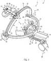
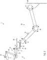
1 : eine schematische ausschnittsweise Perspektivansicht einer Vorrichtung zum Positionieren einer Magnetspule relativ zum Kopf eines Patienten gemäß einer Ausführungsform, insbesondere zum Darstellen diverser Einstellmöglichkeiten der Kopfeinheit;2 : eine schematische Seitenansicht der Vorrichtung gemäß der Ausführungsform;3 : eine der Ansicht aus1 entsprechende, schematische ausschnittsweise Perspektivansicht der Vorrichtung gemäß der Ausführungsform, insbesondere zur Darstellung der beweglichen Verbindung zwischen Haltearm und Kopfeinheit;4A : eine schematische ausschnittsweise Rückansicht auf die Vorrichtung gemäß der Ausführungsform;4B : eine schematische ausschnittsweise Seitenansicht auf die Vorrichtung gemäß der Ausführungsform;4C : eine weitere schematische ausschnittsweise Rückansicht auf die Vorrichtung gemäß der Ausführungsform; und5 : eine schematische Detailansicht desAusschnitts W aus 2 .
1 : a schematic fragmentary perspective view of an apparatus for positioning a magnetic coil relative to the head of a patient according to an embodiment, in particular for illustrating various possible adjustments of the head unit;2 a schematic side view of the device according to the embodiment;3 : one of theview 1 corresponding, schematic fragmentary perspective view of the device according to the embodiment, in particular for illustrating the movable connection between the holding arm and the head unit;4A a schematic fragmentary rear view of the device according to the embodiment;4B FIG. 2 is a schematic fragmentary side view of the device according to the embodiment; FIG.4C a further schematic fragmentary rear view of the device according to the embodiment; and5 : A schematic detail view of the section W from2 ,
Die Figuren zeigen eine Ausführungsform einer erfindungsgemäßen Vorrichtung
Wie zum Beispiel in dem in
Die Kopfeinheit
Zum Einstellen einer gewünschten Position der Magnetspule
Die Positioniereinheit
In der gezeigten Ausführungsform ist die Spulenaufnahme
In der gezeigten Ausführungsform umfasst die Spulenaufnahme
Die Vorrichtung
Der dargestellte Haltearm
Zwischen der Kopfeinheit
Zwischen den Kopplungselementen
Die bewegliche Verbindung
Die bewegliche Verbindung
Die bewegliche Verbindung
Die Translationskopplung
Im Folgenden wird die Einstellung der Position der Magnetspule
Zu Beginn der Einstellung soll zunächst die Kopfeinheit
Nachdem die Nackenstütze
Nachdem die Kopfeinheit
Um für nachfolgende Sitzungen die Einstellung zu vereinfachen, sind Skalen
Während die Schiebeverbindung des Basisbügels
ZITATE ENTHALTEN IN DER BESCHREIBUNG QUOTES INCLUDE IN THE DESCRIPTION
Diese Liste der vom Anmelder aufgeführten Dokumente wurde automatisiert erzeugt und ist ausschließlich zur besseren Information des Lesers aufgenommen. Die Liste ist nicht Bestandteil der deutschen Patent- bzw. Gebrauchsmusteranmeldung. Das DPMA übernimmt keinerlei Haftung für etwaige Fehler oder Auslassungen.This list of the documents listed by the applicant has been generated automatically and is included solely for the better information of the reader. The list is not part of the German patent or utility model application. The DPMA assumes no liability for any errors or omissions.
Zitierte PatentliteraturCited patent literature
- DE 10242542 A1 [0008]DE 10242542 A1 [0008]
- US 6926660 B2 [0009]US 6926660 B2 [0009]
- US 2010/0113959 A1 [0009]US 2010/0113959 A1 [0009]
- US 7651459 B2 [0009]US 7651459 B2 [0009]
- US 8088058 B2 [0009]US8088058 B2 [0009]
- US 2015/0202453 A1 [0009]US 2015/0202453 A1 [0009]
- EP 2252367 B1 [0009]EP 2252367 B1 [0009]
- US 2016/0030762 A1 [0009]US 2016/0030762 A1 [0009]
Claims (20)
Translated fromGermanPriority Applications (3)
| Application Number | Priority Date | Filing Date | Title |
|---|---|---|---|
| DE102017104627.5ADE102017104627A1 (en) | 2017-03-06 | 2017-03-06 | POSITIONING AID FOR TMS |
| US15/906,006US10639491B2 (en) | 2017-03-06 | 2018-02-27 | Positioning aid for transcranial magnetic stimulation |
| EP18159800.4AEP3372278B1 (en) | 2017-03-06 | 2018-03-02 | Positioning aid for tms |
Applications Claiming Priority (1)
| Application Number | Priority Date | Filing Date | Title |
|---|---|---|---|
| DE102017104627.5ADE102017104627A1 (en) | 2017-03-06 | 2017-03-06 | POSITIONING AID FOR TMS |
Publications (1)
| Publication Number | Publication Date |
|---|---|
| DE102017104627A1true DE102017104627A1 (en) | 2018-09-06 |
Family
ID=61563212
Family Applications (1)
| Application Number | Title | Priority Date | Filing Date |
|---|---|---|---|
| DE102017104627.5APendingDE102017104627A1 (en) | 2017-03-06 | 2017-03-06 | POSITIONING AID FOR TMS |
Country Status (3)
| Country | Link |
|---|---|
| US (1) | US10639491B2 (en) |
| EP (1) | EP3372278B1 (en) |
| DE (1) | DE102017104627A1 (en) |
Families Citing this family (26)
| Publication number | Priority date | Publication date | Assignee | Title |
|---|---|---|---|---|
| US20180001107A1 (en) | 2016-07-01 | 2018-01-04 | Btl Holdings Limited | Aesthetic method of biological structure treatment by magnetic field |
| US11247039B2 (en) | 2016-05-03 | 2022-02-15 | Btl Healthcare Technologies A.S. | Device including RF source of energy and vacuum system |
| US11534619B2 (en) | 2016-05-10 | 2022-12-27 | Btl Medical Solutions A.S. | Aesthetic method of biological structure treatment by magnetic field |
| US10583287B2 (en) | 2016-05-23 | 2020-03-10 | Btl Medical Technologies S.R.O. | Systems and methods for tissue treatment |
| US10556122B1 (en) | 2016-07-01 | 2020-02-11 | Btl Medical Technologies S.R.O. | Aesthetic method of biological structure treatment by magnetic field |
| US11141219B1 (en) | 2016-08-16 | 2021-10-12 | BTL Healthcare Technologies, a.s. | Self-operating belt |
| CN109260593B (en)* | 2018-09-27 | 2020-09-08 | 武汉资联虹康科技股份有限公司 | A kind of transcranial magnetic stimulation treatment method and equipment |
| US12156689B2 (en) | 2019-04-11 | 2024-12-03 | Btl Medical Solutions A.S. | Methods and devices for aesthetic treatment of biological structures by radiofrequency and magnetic energy |
| ES2926904T3 (en) | 2019-04-11 | 2022-10-31 | Btl Medical Solutions A S | Device for the aesthetic treatment of biological structures using radiofrequency and magnetic energy |
| US11878167B2 (en) | 2020-05-04 | 2024-01-23 | Btl Healthcare Technologies A.S. | Device and method for unattended treatment of a patient |
| WO2021224678A1 (en) | 2020-05-04 | 2021-11-11 | Btl Medical Technologies S.R.O. | Device and method for unattended treatment of a patient |
| CN111773543A (en)* | 2020-06-08 | 2020-10-16 | 南京伟思医疗科技股份有限公司 | Headrest is followed automatically to support |
| CN111728715A (en)* | 2020-06-08 | 2020-10-02 | 南京伟思医疗科技股份有限公司 | Automatic following mechanism of support |
| CN111728712A (en)* | 2020-06-10 | 2020-10-02 | 南京伟思医疗科技股份有限公司 | Inflatable positioning headrest for transcranial magnetic stimulation and positioning method thereof |
| CN111760208A (en)* | 2020-07-21 | 2020-10-13 | 上海交通大学 | Automatic positioning system and method for human transcranial ultrasound stimulation based on robotic arm |
| WO2022028235A1 (en)* | 2020-08-03 | 2022-02-10 | 南京伟思医疗科技股份有限公司 | Repeat positioning helmet for transcranial magnetic stimulation and use method therefor |
| CN112546447B (en)* | 2020-11-24 | 2021-07-27 | 四川君健万峰医疗器械有限责任公司 | Stimulating coil positioning device |
| CN113598971B (en)* | 2021-08-31 | 2025-01-07 | 成都体育学院 | A transcranial magnetic stimulation positioning ruler |
| CN113616928A (en)* | 2021-09-14 | 2021-11-09 | 宁波市康宁医院(宁波市精神疾病预防控制中心、宁波市微循环与莨菪类药研究所) | Transcranial magnetic stimulation head frame |
| EP4415812A1 (en) | 2021-10-13 | 2024-08-21 | BTL Medical Solutions a.s. | Devices for aesthetic treatment of biological structures by radiofrequency and magnetic energy |
| US11896816B2 (en) | 2021-11-03 | 2024-02-13 | Btl Healthcare Technologies A.S. | Device and method for unattended treatment of a patient |
| CN113995972A (en)* | 2021-11-26 | 2022-02-01 | 无锡海鹰医疗科技股份有限公司 | Upper HIFU separation water sac bracket |
| US20230320916A1 (en)* | 2022-04-06 | 2023-10-12 | Christian Hirschbeck | Anatomically Adaptable Headrest Apparatus |
| CN114904143B (en)* | 2022-05-19 | 2025-04-11 | 四川君健万峰医疗器械有限责任公司 | A head-mounted transcranial magnetic stimulation coil device |
| CN117547733A (en)* | 2023-11-13 | 2024-02-13 | 武汉依瑞德医疗设备新技术有限公司 | A transcranial magnetic stimulation therapy device positioning system and method thereof |
| CN118022188A (en)* | 2023-11-25 | 2024-05-14 | 上海市浦东新区精神卫生中心(同济大学附属精神卫生中心、上海市浦东新区心理咨询中心) | Transcranial magnetic stimulation coil positioning and skull fixing device |
Citations (8)
| Publication number | Priority date | Publication date | Assignee | Title |
|---|---|---|---|---|
| DE10242542A1 (en) | 2002-09-13 | 2004-04-01 | Forschungszentrum Karlsruhe Gmbh | Positioning system for navigated trans-cranial magnetic stimulation has support with fixing elements for head that do not restrict field of view, frame with motorized stimulation coil positioning |
| US6926660B2 (en) | 2003-03-07 | 2005-08-09 | Neuronetics, Inc. | Facilitating treatment via magnetic stimulation |
| US7651459B2 (en) | 2004-01-06 | 2010-01-26 | Neuronetics, Inc. | Method and apparatus for coil positioning for TMS studies |
| US20100113959A1 (en) | 2006-03-07 | 2010-05-06 | Beth Israel Deaconess Medical Center, Inc. | Transcranial magnetic stimulation (tms) methods and apparatus |
| US8088058B2 (en) | 2005-01-20 | 2012-01-03 | Neuronetics, Inc. | Articulating arm |
| US20150202453A1 (en) | 2014-01-22 | 2015-07-23 | University Of Florida Research Foundation, Incorporated | Securing a tms coil to the patient's head |
| EP2252367B1 (en) | 2008-03-10 | 2015-09-09 | Neuronetics, Inc. | Apparatus for coil positioning for tms studies |
| US20160030762A1 (en) | 2013-03-15 | 2016-02-04 | Neuhorizon Medical Corporation | Device and method for transcranial magnetic stimulation coil positioning with data integration |
Family Cites Families (8)
| Publication number | Priority date | Publication date | Assignee | Title |
|---|---|---|---|---|
| WO2003098268A1 (en) | 2002-05-17 | 2003-11-27 | Musc Foundation For Research Development | Method, apparatus, and system for automatically positioning a probe or sensor |
| DE102004006192B4 (en)* | 2004-02-06 | 2008-11-06 | Axel Muntermann | Device for treatment with magnetic fields |
| US7976451B2 (en)* | 2005-06-16 | 2011-07-12 | The United States Of America As Represented By The Department Of Health And Human Services | Transcranial magnetic stimulation system and methods |
| US20080262287A1 (en) | 2007-04-14 | 2008-10-23 | Etis Investments, Inc. | System for delivery of magnetic stimulation |
| DE102008034237B4 (en) | 2008-07-23 | 2011-06-30 | Matthäus, Lars, Dipl.-Math.techn., 23562 | Positioning system for transcranial magnetic stimulation |
| US20160015588A1 (en)* | 2013-04-02 | 2016-01-21 | Teijin Pharma Limited | Head positioning device, medical system, medical instrument positioning device, and holding shell |
| PL2878336T3 (en) | 2013-11-29 | 2020-07-27 | Nexstim Oyj | Device support apparatus |
| WO2016056326A1 (en) | 2014-10-07 | 2016-04-14 | 帝人ファーマ株式会社 | Transcranial magnetic stimulation system |
- 2017
- 2017-03-06DEDE102017104627.5Apatent/DE102017104627A1/enactivePending
- 2018
- 2018-02-27USUS15/906,006patent/US10639491B2/enactiveActive
- 2018-03-02EPEP18159800.4Apatent/EP3372278B1/enactiveActive
Patent Citations (8)
| Publication number | Priority date | Publication date | Assignee | Title |
|---|---|---|---|---|
| DE10242542A1 (en) | 2002-09-13 | 2004-04-01 | Forschungszentrum Karlsruhe Gmbh | Positioning system for navigated trans-cranial magnetic stimulation has support with fixing elements for head that do not restrict field of view, frame with motorized stimulation coil positioning |
| US6926660B2 (en) | 2003-03-07 | 2005-08-09 | Neuronetics, Inc. | Facilitating treatment via magnetic stimulation |
| US7651459B2 (en) | 2004-01-06 | 2010-01-26 | Neuronetics, Inc. | Method and apparatus for coil positioning for TMS studies |
| US8088058B2 (en) | 2005-01-20 | 2012-01-03 | Neuronetics, Inc. | Articulating arm |
| US20100113959A1 (en) | 2006-03-07 | 2010-05-06 | Beth Israel Deaconess Medical Center, Inc. | Transcranial magnetic stimulation (tms) methods and apparatus |
| EP2252367B1 (en) | 2008-03-10 | 2015-09-09 | Neuronetics, Inc. | Apparatus for coil positioning for tms studies |
| US20160030762A1 (en) | 2013-03-15 | 2016-02-04 | Neuhorizon Medical Corporation | Device and method for transcranial magnetic stimulation coil positioning with data integration |
| US20150202453A1 (en) | 2014-01-22 | 2015-07-23 | University Of Florida Research Foundation, Incorporated | Securing a tms coil to the patient's head |
Also Published As
| Publication number | Publication date |
|---|---|
| US20180250521A1 (en) | 2018-09-06 |
| EP3372278A1 (en) | 2018-09-12 |
| EP3372278B1 (en) | 2021-01-27 |
| US10639491B2 (en) | 2020-05-05 |
Similar Documents
| Publication | Publication Date | Title |
|---|---|---|
| EP3372278B1 (en) | Positioning aid for tms | |
| EP1785093B1 (en) | Imaging apparatus and therapy system incorporating such an imaging apparatus | |
| DE69938384T2 (en) | Carrying system for components of an X-ray imaging device | |
| AT506257B1 (en) | DEVICE FOR PRODUCING PHOTOGRAPHIC PHOTOGRAPHIC RECORDINGS | |
| EP0226732B1 (en) | Device for photogrammetrically recording the human head | |
| DE4432606A1 (en) | Device for accommodating at least one sonographic probe | |
| DE10242542A1 (en) | Positioning system for navigated trans-cranial magnetic stimulation has support with fixing elements for head that do not restrict field of view, frame with motorized stimulation coil positioning | |
| DE102020101602A1 (en) | Assistant device | |
| WO2012059227A1 (en) | Assembly and method for the automatic rough positioning of ophthalmological equipment | |
| CH677182A5 (en) | ||
| DE112016004468T5 (en) | Head-mounted display unit and mounting frame for head-mounted display unit | |
| WO2019120553A1 (en) | Optical device | |
| DE102008035196A1 (en) | Diagnostic device i.e. X-ray diagnostic device, has image recording units, which are held by articulated arm robot directly or by support, and cable guide provided at robot arm for supply line | |
| DE60036442T2 (en) | Method for adjusting or readjusting medical images on a patient, and associated device | |
| DE3038548A1 (en) | CRANIOSTAT, ESPECIALLY FOR THE AMBULATORY RADIOGRAPHY OF THE TEMPORO-MANDIBULAR JOINT | |
| DE4004248A1 (en) | Seeing aid with head frame - has binoculars adjustable to different predetermined distances and for angle | |
| DE202017104364U1 (en) | Device for detecting movements of a lower jaw relative to the upper jaw of a vertebrate | |
| DE102004062337B4 (en) | Mobile tonometer for non-contact self-tonometry | |
| DE102008051223A1 (en) | Device for seating, particularly therapy chair, has seat surface and pelvis part for laying back part of human pelvis, and rear part for laying back at back of body | |
| DE102010020275A1 (en) | Operation support for brain tumor patient, has shackle comprising hole through which bolt is penetrated from bottom and screwed together with nut, so that ball socket is fixed upon lower frame | |
| LU507051B1 (en) | Ein hilfsgerät für den schutz vor kurzsichtigkeit in der augenheilkunde mit anpassbaren verhaltenserinnerungen | |
| Johnston et al. | A head-mounted scene holder for eye movement research | |
| DE4200748A1 (en) | Stereo-tactile device for aligning puncturing instrument on target - locates device in back region of patient body comprising rectangular baseplate and two mutually parallel guide rails arranged spaced inwards from two parallel sides. | |
| EP3630003A1 (en) | Mandibular joint recording system | |
| DE2616445A1 (en) | PORTABLE EYE CHECK DEVICE FOR MEASURING ARBITRAL AND INVOLVED EYE MOVEMENTS |
Legal Events
| Date | Code | Title | Description |
|---|---|---|---|
| R163 | Identified publications notified | ||
| R082 | Change of representative | Representative=s name:NOVENTIVE PATENTANWALTSGESELLSCHAFT MBH, DE | |
| R012 | Request for examination validly filed |