DE102017103198A1 - Device for determining and retrieving a reference point during a surgical procedure - Google Patents
Device for determining and retrieving a reference point during a surgical procedureDownload PDFInfo
- Publication number
- DE102017103198A1 DE102017103198A1DE102017103198.7ADE102017103198ADE102017103198A1DE 102017103198 A1DE102017103198 A1DE 102017103198A1DE 102017103198 ADE102017103198 ADE 102017103198ADE 102017103198 A1DE102017103198 A1DE 102017103198A1
- Authority
- DE
- Germany
- Prior art keywords
- endoscope
- control unit
- image
- optical axis
- point
- Prior art date
- Legal status (The legal status is an assumption and is not a legal conclusion. Google has not performed a legal analysis and makes no representation as to the accuracy of the status listed.)
- Withdrawn
Links
- 238000001356surgical procedureMethods0.000titleclaimsabstractdescription35
- 230000003287optical effectEffects0.000claimsabstractdescription84
- 239000013598vectorSubstances0.000claimsdescription60
- 238000000034methodMethods0.000claimsdescription17
- 230000000007visual effectEffects0.000claimsdescription11
- 239000003550markerSubstances0.000claimsdescription9
- 230000001419dependent effectEffects0.000claimsdescription8
- 238000003384imaging methodMethods0.000claimsdescription5
- 230000011664signalingEffects0.000claimsdescription5
- 239000012636effectorSubstances0.000description28
- 210000000056organAnatomy0.000description10
- 230000008878couplingEffects0.000description9
- 238000010168coupling processMethods0.000description9
- 238000005859coupling reactionMethods0.000description9
- 238000002432robotic surgeryMethods0.000description4
- 230000005540biological transmissionEffects0.000description3
- 230000008859changeEffects0.000description3
- 238000011161developmentMethods0.000description3
- 230000018109developmental processEffects0.000description3
- 239000003086colorantSubstances0.000description2
- 238000005286illuminationMethods0.000description2
- 238000002357laparoscopic surgeryMethods0.000description2
- 238000012634optical imagingMethods0.000description2
- 238000003909pattern recognitionMethods0.000description2
- 238000012567pattern recognition methodMethods0.000description2
- 238000002560therapeutic procedureMethods0.000description2
- 238000004148unit processMethods0.000description2
- 238000011179visual inspectionMethods0.000description2
- BUHVIAUBTBOHAG-FOYDDCNASA-N(2r,3r,4s,5r)-2-[6-[[2-(3,5-dimethoxyphenyl)-2-(2-methylphenyl)ethyl]amino]purin-9-yl]-5-(hydroxymethyl)oxolane-3,4-diolChemical compoundCOC1=CC(OC)=CC(C(CNC=2C=3N=CN(C=3N=CN=2)[C@H]2[C@@H]([C@H](O)[C@@H](CO)O2)O)C=2C(=CC=CC=2)C)=C1BUHVIAUBTBOHAG-FOYDDCNASA-N0.000description1
- 230000004913activationEffects0.000description1
- 210000003484anatomyAnatomy0.000description1
- 238000013459approachMethods0.000description1
- 230000000740bleeding effectEffects0.000description1
- 230000003247decreasing effectEffects0.000description1
- 238000006073displacement reactionMethods0.000description1
- 238000007688edgingMethods0.000description1
- 239000004744fabricSubstances0.000description1
- 239000000835fiberSubstances0.000description1
- 230000002262irrigationEffects0.000description1
- 238000003973irrigationMethods0.000description1
- 238000002324minimally invasive surgeryMethods0.000description1
- 238000012978minimally invasive surgical procedureMethods0.000description1
- 230000002093peripheral effectEffects0.000description1
- 238000001454recorded imageMethods0.000description1
- 239000000523sampleSubstances0.000description1
- 230000008054signal transmissionEffects0.000description1
- 239000007787solidSubstances0.000description1
- 238000013519translationMethods0.000description1
- 238000012800visualizationMethods0.000description1
Images


Classifications
- A—HUMAN NECESSITIES
- A61—MEDICAL OR VETERINARY SCIENCE; HYGIENE
- A61B—DIAGNOSIS; SURGERY; IDENTIFICATION
- A61B1/00—Instruments for performing medical examinations of the interior of cavities or tubes of the body by visual or photographical inspection, e.g. endoscopes; Illuminating arrangements therefor
- A61B1/00002—Operational features of endoscopes
- A61B1/00004—Operational features of endoscopes characterised by electronic signal processing
- A61B1/00009—Operational features of endoscopes characterised by electronic signal processing of image signals during a use of endoscope
- A61B1/000094—Operational features of endoscopes characterised by electronic signal processing of image signals during a use of endoscope extracting biological structures
- A—HUMAN NECESSITIES
- A61—MEDICAL OR VETERINARY SCIENCE; HYGIENE
- A61B—DIAGNOSIS; SURGERY; IDENTIFICATION
- A61B1/00—Instruments for performing medical examinations of the interior of cavities or tubes of the body by visual or photographical inspection, e.g. endoscopes; Illuminating arrangements therefor
- A61B1/00002—Operational features of endoscopes
- A61B1/00043—Operational features of endoscopes provided with output arrangements
- A61B1/00045—Display arrangement
- A—HUMAN NECESSITIES
- A61—MEDICAL OR VETERINARY SCIENCE; HYGIENE
- A61B—DIAGNOSIS; SURGERY; IDENTIFICATION
- A61B1/00—Instruments for performing medical examinations of the interior of cavities or tubes of the body by visual or photographical inspection, e.g. endoscopes; Illuminating arrangements therefor
- A61B1/00163—Optical arrangements
- A61B1/00193—Optical arrangements adapted for stereoscopic vision
- A—HUMAN NECESSITIES
- A61—MEDICAL OR VETERINARY SCIENCE; HYGIENE
- A61B—DIAGNOSIS; SURGERY; IDENTIFICATION
- A61B1/00—Instruments for performing medical examinations of the interior of cavities or tubes of the body by visual or photographical inspection, e.g. endoscopes; Illuminating arrangements therefor
- A61B1/04—Instruments for performing medical examinations of the interior of cavities or tubes of the body by visual or photographical inspection, e.g. endoscopes; Illuminating arrangements therefor combined with photographic or television appliances
- A61B1/045—Control thereof
- A—HUMAN NECESSITIES
- A61—MEDICAL OR VETERINARY SCIENCE; HYGIENE
- A61B—DIAGNOSIS; SURGERY; IDENTIFICATION
- A61B34/00—Computer-aided surgery; Manipulators or robots specially adapted for use in surgery
- A61B34/20—Surgical navigation systems; Devices for tracking or guiding surgical instruments, e.g. for frameless stereotaxis
- A—HUMAN NECESSITIES
- A61—MEDICAL OR VETERINARY SCIENCE; HYGIENE
- A61B—DIAGNOSIS; SURGERY; IDENTIFICATION
- A61B34/00—Computer-aided surgery; Manipulators or robots specially adapted for use in surgery
- A61B34/25—User interfaces for surgical systems
- A—HUMAN NECESSITIES
- A61—MEDICAL OR VETERINARY SCIENCE; HYGIENE
- A61B—DIAGNOSIS; SURGERY; IDENTIFICATION
- A61B34/00—Computer-aided surgery; Manipulators or robots specially adapted for use in surgery
- A61B34/30—Surgical robots
- A—HUMAN NECESSITIES
- A61—MEDICAL OR VETERINARY SCIENCE; HYGIENE
- A61B—DIAGNOSIS; SURGERY; IDENTIFICATION
- A61B34/00—Computer-aided surgery; Manipulators or robots specially adapted for use in surgery
- A61B34/30—Surgical robots
- A61B34/35—Surgical robots for telesurgery
- A—HUMAN NECESSITIES
- A61—MEDICAL OR VETERINARY SCIENCE; HYGIENE
- A61B—DIAGNOSIS; SURGERY; IDENTIFICATION
- A61B34/00—Computer-aided surgery; Manipulators or robots specially adapted for use in surgery
- A61B34/70—Manipulators specially adapted for use in surgery
- A—HUMAN NECESSITIES
- A61—MEDICAL OR VETERINARY SCIENCE; HYGIENE
- A61B—DIAGNOSIS; SURGERY; IDENTIFICATION
- A61B5/00—Measuring for diagnostic purposes; Identification of persons
- A61B5/06—Devices, other than using radiation, for detecting or locating foreign bodies ; Determining position of diagnostic devices within or on the body of the patient
- A—HUMAN NECESSITIES
- A61—MEDICAL OR VETERINARY SCIENCE; HYGIENE
- A61B—DIAGNOSIS; SURGERY; IDENTIFICATION
- A61B1/00—Instruments for performing medical examinations of the interior of cavities or tubes of the body by visual or photographical inspection, e.g. endoscopes; Illuminating arrangements therefor
- A61B1/00002—Operational features of endoscopes
- A61B1/00039—Operational features of endoscopes provided with input arrangements for the user
- A61B1/00042—Operational features of endoscopes provided with input arrangements for the user for mechanical operation
- A—HUMAN NECESSITIES
- A61—MEDICAL OR VETERINARY SCIENCE; HYGIENE
- A61B—DIAGNOSIS; SURGERY; IDENTIFICATION
- A61B1/00—Instruments for performing medical examinations of the interior of cavities or tubes of the body by visual or photographical inspection, e.g. endoscopes; Illuminating arrangements therefor
- A61B1/04—Instruments for performing medical examinations of the interior of cavities or tubes of the body by visual or photographical inspection, e.g. endoscopes; Illuminating arrangements therefor combined with photographic or television appliances
- A61B1/042—Instruments for performing medical examinations of the interior of cavities or tubes of the body by visual or photographical inspection, e.g. endoscopes; Illuminating arrangements therefor combined with photographic or television appliances characterised by a proximal camera, e.g. a CCD camera
- A—HUMAN NECESSITIES
- A61—MEDICAL OR VETERINARY SCIENCE; HYGIENE
- A61B—DIAGNOSIS; SURGERY; IDENTIFICATION
- A61B34/00—Computer-aided surgery; Manipulators or robots specially adapted for use in surgery
- A61B34/20—Surgical navigation systems; Devices for tracking or guiding surgical instruments, e.g. for frameless stereotaxis
- A61B2034/2046—Tracking techniques
- A61B2034/2065—Tracking using image or pattern recognition
- A—HUMAN NECESSITIES
- A61—MEDICAL OR VETERINARY SCIENCE; HYGIENE
- A61B—DIAGNOSIS; SURGERY; IDENTIFICATION
- A61B34/00—Computer-aided surgery; Manipulators or robots specially adapted for use in surgery
- A61B34/30—Surgical robots
- A61B2034/302—Surgical robots specifically adapted for manipulations within body cavities, e.g. within abdominal or thoracic cavities
- A—HUMAN NECESSITIES
- A61—MEDICAL OR VETERINARY SCIENCE; HYGIENE
- A61B—DIAGNOSIS; SURGERY; IDENTIFICATION
- A61B90/00—Instruments, implements or accessories specially adapted for surgery or diagnosis and not covered by any of the groups A61B1/00 - A61B50/00, e.g. for luxation treatment or for protecting wound edges
- A61B90/36—Image-producing devices or illumination devices not otherwise provided for
- A61B2090/364—Correlation of different images or relation of image positions in respect to the body
- A61B2090/365—Correlation of different images or relation of image positions in respect to the body augmented reality, i.e. correlating a live optical image with another image
- A—HUMAN NECESSITIES
- A61—MEDICAL OR VETERINARY SCIENCE; HYGIENE
- A61B—DIAGNOSIS; SURGERY; IDENTIFICATION
- A61B5/00—Measuring for diagnostic purposes; Identification of persons
- A61B5/74—Details of notification to user or communication with user or patient; User input means
- A61B5/7405—Details of notification to user or communication with user or patient; User input means using sound
- A61B5/7415—Sound rendering of measured values, e.g. by pitch or volume variation
- A—HUMAN NECESSITIES
- A61—MEDICAL OR VETERINARY SCIENCE; HYGIENE
- A61B—DIAGNOSIS; SURGERY; IDENTIFICATION
- A61B5/00—Measuring for diagnostic purposes; Identification of persons
- A61B5/74—Details of notification to user or communication with user or patient; User input means
- A61B5/7455—Details of notification to user or communication with user or patient; User input means characterised by tactile indication, e.g. vibration or electrical stimulation
Landscapes
- Health & Medical Sciences (AREA)
- Life Sciences & Earth Sciences (AREA)
- Surgery (AREA)
- Engineering & Computer Science (AREA)
- Animal Behavior & Ethology (AREA)
- Public Health (AREA)
- Veterinary Medicine (AREA)
- General Health & Medical Sciences (AREA)
- Molecular Biology (AREA)
- Medical Informatics (AREA)
- Heart & Thoracic Surgery (AREA)
- Biomedical Technology (AREA)
- Nuclear Medicine, Radiotherapy & Molecular Imaging (AREA)
- Physics & Mathematics (AREA)
- Pathology (AREA)
- Biophysics (AREA)
- Radiology & Medical Imaging (AREA)
- Optics & Photonics (AREA)
- Robotics (AREA)
- Signal Processing (AREA)
- Human Computer Interaction (AREA)
- Endoscopes (AREA)
Abstract
Translated fromGerman
Description
Translated fromGermanDie Erfindung betrifft eine Vorrichtung zum Festlegen und Wiederauffinden eines Bezugspunkts während eines chirurgischen Eingriffs. Die Vorrichtung umfasst ein Endoskop, das mehrere Bilder nacheinander als Bildfolge erfasst und den Bildern entsprechende Bilddaten erzeugt. Mindestens eine Steuereinheit verarbeitet die Bilddaten und gibt den Bilddaten entsprechende Bilder auf mindestens einer Anzeigeeinheit aus. Durch eine Bedieneingabe über eine Benutzerschnittstelle wird ein Bezugspunkt festgelegt, der im weiteren Verlauf des chirurgischen Eingriffs wieder auffindbar sein soll.The invention relates to a device for determining and retrieving a reference point during a surgical procedure. The device comprises an endoscope which captures a plurality of images successively as an image sequence and generates image data corresponding to the images. At least one control unit processes the image data and outputs images corresponding to the image data on at least one display unit. Through an operator input via a user interface, a reference point is determined, which should be retrievable in the further course of the surgical procedure.
Die Vorrichtung wird insbesondere in einem System zur robotergestützten Chirurgie, insbesondere zu einer telerobotergestützten Prozedur, eingesetzt. Das System hat mindestens einen mit dem Endoskop verbundenen Manipulatorarm und/oder einen mit einem chirurgischen Instrument zur Gewebemanipulation verbundenen Manipulatorarm. Solche Systeme werden auch als Manipulatoren oder Telemanipulatoren oder OP-Roboter bezeichnet.The device is used in particular in a system for robot-assisted surgery, in particular for a telerobot-assisted procedure. The system has at least one manipulator arm connected to the endoscope and / or a manipulator arm connected to a tissue manipulation surgical instrument. Such systems are also referred to as manipulators or telemanipulators or surgical robots.
In den Dokumenten
Bei minimalinvasiven ausgeführten chirurgischen Eingriffen, insbesondere bei der Laparoskopie, werden die für Gewebemanipulationen beim chirurgischen Eingriff erforderlichen chirurgischen Instrumente durch sogenannte Trokare in den zu operierenden Patienten eingeführt. Zusätzlich zu den zur Gewebemanipulation einzuführenden chirurgischen Instrumenten wird ein Endoskop durch einen weiteren Trokar zur Aufnahme von Bildern des Operationssitus während des chirurgischen Eingriffs in den Körper des Patienten eingeführt. Beim chirurgischen Eingriff nutzt der Chirurg das auf einer Anzeigeeinheit dargestellte Livebild des Operationssitus, um sich zu orientieren, erforderliche Gewebemanipulationen festlegen und in Echtzeit ausführen zu können sowie für den Therapieverlauf relevante Entscheidungen treffen zu können. Dazu hat der Chirurg zumindest einen Teil der Endeffektoren der Instrumente, mit denen er das Gewebe manipuliert, im Sichtfeld des Endoskops. Diese Arbeitsweise ist sowohl bei manuell ausgeführten chirurgischen Eingriffen mit manuell betätigbaren chirurgischen Instrumenten als auch bei chirurgischen Eingriffen, die mithilfe eines Telemanipulators bei einer robotergestützten Chirurgie durchgeführt werden, gleich. Bei dem Einsatz eines Telemanipulators werden die Position und die Orientierung der chirurgischen Instrumente sowie die Position und Orientierung des Endoskops durch Manipulatorarme des Telemanipulators geführt. Der Chirurg steuert die Manipulatorarme und die chirurgischen Instrumente durch haptische Eingabegeräte fern.In minimally invasive surgical procedures performed, in particular in laparoscopy, the surgical instruments required for tissue manipulation during surgery are introduced by so-called trocars into the patients to be operated on. In addition to the surgical instruments to be introduced for tissue manipulation, an endoscope is inserted through another trocar for receiving images of the surgical site during surgery into the patient's body. During a surgical procedure, the surgeon uses the live image of the surgical site displayed on a display unit in order to be able to orientate himself, to determine necessary tissue manipulations and to execute them in real time and to be able to make decisions relevant to the course of therapy. For this, the surgeon has at least a portion of the end effectors of the instruments with which he manipulates the tissue, in the field of view of the endoscope. This procedure is the same for both manually performed surgical procedures with manually operable surgical instruments and for surgical procedures performed using a telemanipulator in robotic surgery. When using a telemanipulator, the position and orientation of the surgical instruments as well as the position and orientation of the endoscope are guided by manipulator arms of the telemanipulator. The surgeon controls the manipulator arms and surgical instruments with haptic input devices.
Im Verlauf eines chirurgischen Eingriffs kann es für den Chirurgen erforderlich sein, dass er das Endoskop auf bestimmte anatomische Merkmale oder Strukturen ausrichtet, um insbesondere eine gute Sicht auf zu manipulierendes Gewebe oder auf plötzlich auftretende Blutungen auszurichten. Nur so ist es dem Chirurgen möglich, die relevanten Merkmale oder Strukturen visuell zu begutachten und Entscheidungen für den weiteren Therapieverlauf zu treffen. Dabei ist es auch möglich, dass ein chirurgisches Instrument oder mehrere chirurgische Instrumente aus dem Sichtfeld des Endoskops verschwinden, so dass der Chirurg keine visuelle Kontrolle mehr über die Instrumente hat. Für eine Gewebemanipulation ist jedoch eine Sichtkontrolle erforderlich, so dass der Chirurg das Endoskop vor einer Gewebemanipulation wieder so auszurichten hat, dass er die Instrumente im Sichtfeld hat, die er zur Gewebemanipulation nutzen will. Grundsätzlich sollte zur Patientensicherheit ein Bewegen der Instrumente ohne Sichtkontrolle vermieden werden.In the course of a surgical procedure, the surgeon may be required to orient the endoscope to particular anatomical features or structures, particularly to provide a good view of tissue to be manipulated or on sudden bleeding. Only then is it possible for the surgeon to visually assess the relevant features or structures and make decisions for the further course of therapy. It is also possible that a surgical instrument or several surgical instruments disappear from the field of view of the endoscope, so that the surgeon no longer has visual control over the instruments. However, visual inspection is required for tissue manipulation so that the surgeon must reorient the endoscope prior to tissue manipulation so as to have the instruments in the field of vision that he intends to use for tissue manipulation. Basically, patient safety should be avoided by moving the instruments without visual inspection.
Aus dem Dokument
Aus dem Dokument
Aufgabe der Erfindung ist es, eine Vorrichtung zum Festlegen und Wiederauffinden eines Bezugspunkts während eines chirurgischen Eingriffs anzugeben, durch das einem Chirurgen während eines chirurgischen Eingriffs das Wiederauffinden des Bezugspunkts erleichtert wird.The object of the invention is to provide a device for determining and retrieving a reference point during a surgical procedure by which a surgeon during a surgical procedure, the retrieval of the reference point is facilitated.
Diese Aufgabe wird sowohl durch eine Vorrichtung zum Festlegen und Wiederauffinden eines Bezugspunkts während eines chirurgischen Eingriffs mit den Merkmalen des Patentanspruchs 1 als auch durch eine Vorrichtung mit den Merkmalen des Anspruchs 2 gelöst. Vorteilhafte Weiterbildungen sind für beide Vorrichtungen in den abhängigen Ansprüchen angegeben.This object is achieved both by a device for determining and retrieving a reference point during a surgical procedure with the features of
Durch den ermittelten Abstandsvektor zwischen der ersten Position und der zweiten Position kann bei der Vorrichtung nach Anspruch 1 sowie bei der Vorrichtung nach Anspruch 2 der festgelegte Bezugspunkt bzw. das chirurgische Instrument mithilfe der auf dem Abstandsvektor basierenden Information einfach wiedergefunden werden, wobei ein Chirurg das Endoskop insbesondere so bewegen kann, dass der Bezugspunkt bzw. das chirurgische Instrument wieder in den Sichtbereich des Endoskops gelangt.The determined distance vector between the first position and the second position, in the device according to
Allgemein hat die Erfindung den Zweck, eine Information zu erzeugen, die dazu verwendet werden kann, dem Chirurgen durch die Ausgabe visueller, haptischer oder akustischer Signale ein Ausrichten des Endoskops derart zu ermöglichen, dass die Instrumente und/oder ein anderer Bezugspunkt wieder im Sichtfeld des Endoskops sind. Bei der Ausgabe visueller Informationen in Verbindung mit einer 3D-Anzeige, wie einem stereoskopischen Display, kann eine Richtungsinformation insbesondere als 3D-Vektor angezeigt werden. Ferner hat die Erfindung den Zweck, dass ein Chirurg während eines chirurgischen Eingriffs einen Bezugspunkt bzw. eine virtuelle Landmark, im Operationssitus definieren kann, wobei eine Information erzeugt wird, welche dem Chirurgen das Wiederauffinden dieses Bezugspunkts durch die Ausgabe visueller, haptischer oder akustischer Signale ermöglicht. Hierdurch ist es dem Chirurgen insbesondere möglich, das Endoskop so auszurichten, dass der Bezugspunkt im Sichtfeld des Endoskops erscheint.In general, the invention has the purpose of generating information that can be used to allow the surgeon to align the endoscope by issuing visual, haptic or acoustic signals such that the instruments and / or another reference point are again within the field of vision of the endoscope Endoscopes are. When outputting visual information in conjunction with a 3D display, such as a stereoscopic display, direction information can be displayed in particular as a 3D vector. Further, the invention has the purpose of allowing a surgeon during surgery to define a landmark in the surgical site, generating information that allows the surgeon to retrieve that reference by outputting visual, haptic or auditory signals , In this way, it is possible in particular for the surgeon to align the endoscope so that the reference point appears in the field of view of the endoscope.
Die erste und zweite Position nach Anspruch 1 oder 2 können insbesondere in einem dreidimensionalen Patientenkoordinatensystem oder einem dreidimensionalen Instrumentenkoordinatensystem ermittelt werden.The first and second positions according to
Vorteilhaft ist es, wenn die Steuereinheit einen Bereich um einen festgelegten Bezugspunkt, d.h. um den festgelegten ersten Bezugspunkt oder einen festgelegten weiteren Bezugspunkt, mithilfe einer Markierung markiert oder dass die Steuereinheit einen Bereich um einen festgelegten Bezugspunkt des chirurgischen Instruments mithilfe einer Markierung markiert. Dieser Bezugspunkt des chirurgischen Instruments, kann die Instrumentenspitze, insbesondere die Spitze des Endeffektors oder eine Schnittstelle zwischen Schaft und Endeffektor, sein. Der Bezugspunkt nach Anspruch 1 bzw. der Bezugspunkt am chirurgischen Instrument dient somit als Orientierungspunkt. Aufgrund der bekannten Kinematikstruktur bzw. der kinematischen Kette können die genauen Koordinaten der Punkte, insbesondere der Orientierungspunkte und der Bezugspunkte bestimmt werden. Die auf dem Abstandsvektor basierende ausgegebene Information dient als Orientierungshilfe beim Bewegen eines Endoskops, um beispielsweise den Bezugspunkt des chirurgischen Instruments oder ein zuvor festgelegter Bezugspunkt in den Sichtbereich des Endoskops zu bringen.It is advantageous if the control unit covers an area around a defined reference point, i. marked by a marker around the specified first reference point or a defined further reference point or by the control unit marking a region around a defined reference point of the surgical instrument by means of a marker. This reference point of the surgical instrument may be the instrument tip, in particular the tip of the end effector or an interface between the shaft and end effector. The reference point according to
Eine Markierung des Bereichs um den festgelegten Bezugspunkt erfolgt vorzugsweise dadurch, dass ein Organ am Bezugspunkt oder in unmittelbarer Nähe des Bezugspunkts befindliches Organ oder eine am Bezugspunkt oder in unmittelbarer Nähe des Bezugspunkts befindliche Gewebestruktur, insbesondere mithilfe eines Mustererkennungsverfahrens, detektiert und dieses Organ bzw. diese Gewebestruktur mit einer Markierung versehen wird. Insbesondere können die Gewebestruktur bzw. das Organ zur Markierung eingefärbt dargestellt werden. Somit ist es einfach möglich, mithilfe der festgelegten Bezugspunkte, die als anatomische Landmarken dienen, mittels eines nachfolgend vom Endoskop aufgenommenen Bildes wiederzuerkennen, indem eine Extraktion von geeigneten Objektmerkmalen zur Klassifizierung um des Organs oder der Gewebestruktur oder des Bezugspunkts erfolgt.A marking of the area around the defined reference point is preferably carried out by detecting an organ at the reference point or in the immediate vicinity of the reference point or a tissue structure located at the reference point or in the immediate vicinity of the reference point, in particular by means of a pattern recognition method, and this organ or these Fabric structure is provided with a marker. In particular, the tissue structure or the organ can be colored to mark. Thus, it is easily possible to recognize by means of the fixed reference points serving as anatomical landmarks, by means of an image taken subsequently by the endoscope, by extracting suitable object features for classification around the organ or tissue structure or the reference point.
Besonders vorteilhaft ist es, wenn die Steuereinheit einen Bildausschnitt der Umgebung der ermittelten ersten Position beim Ermitteln der ersten Position erfasst und zum Wiederauffinden der ersten Position in einem nach dem Ermitteln der ersten Position erfassten weiteren Bild mit mindestens einem Bildausschnitt des weiteren Bildes vergleicht. Hierzu kann die Steuereinheit insbesondere Verfahren der Mustererkennung von Gewebestrukturen und zur Mustererkennung von Organen ausführen. Alternativ oder zusätzlich kann ein automatisches Auffinden der ersten Position mithilfe der Steuereinheit durch Ausführen eines Verfahrens zur Korrelation zwischen den abgespeicherten Objektmerkmalen eines an der ersten Position detektierten Objekts und den aus einem jeweils aktuell aufgenommenen Bild extrahierten Objektmerkmalen erfolgen. Das automatische Auffinden durch einen Bildvergleich erfolgt insbesondere unter Berücksichtigung von Rotation, Translation, Skalierung und Verformung, wobei beispielsweise ein sogenanntes Warping-Verfahren eingesetzt wird. Hierdurch sind ein Wiederauffinden und vorzugsweise auch ein Markieren der ersten Position in einem weiteren Bild einfach möglich.It is particularly advantageous if the control unit acquires an image section of the surroundings of the determined first position when determining the first position and compares it with at least one image section of the further image to retrieve the first position in a further image captured after the first position has been determined. For this purpose, the control unit can in particular perform methods of pattern recognition of tissue structures and pattern recognition of organs. Alternatively or additionally, an automatic finding of the first position by means of the control unit can take place by executing a method for correlation between the stored object features of an object detected at the first position and the object features extracted from a respective currently recorded image. The automatic finding by an image comparison takes place in particular taking into account rotation, translation, scaling and deformation, wherein for example a so-called warping method is used. As a result, a retrieval and preferably also a marking of the first position in another image are easily possible.
Ferner ist es vorteilhaft, wenn die Steuereinheit die erste Position ausgehend von einem mithilfe des Endoskops erfassten ersten Bildes oder ausgehend von der Position des Endoskops zum ersten Zeitpunkt oder ausgehend von der Position des chirurgischen Instrumentes ermittelt, und wenn die Steuereinheit die zweite Position ausgehend von einem nach dem ersten Bild mithilfe des Endoskops erfassten zweiten Bildes oder ausgehend von der Position des Endoskops zum zweiten Zeitpunkt ermittelt. Hierdurch muss die Position des Punkts nicht aufwendig ermittelt werden, sondern kann einfach aus der Position des Endoskops bzw. der Position des chirurgischen Instruments bestimmt werden.Furthermore, it is advantageous if the control unit determines the first position on the basis of a first image acquired by the endoscope or on the position of the endoscope at the first time or on the position of the surgical instrument, and if the control unit determines the second position on the basis of a determined after the first image using the endoscope second image or based on the position of the endoscope at the second time. As a result, the position of the point need not be determined consuming, but can be easily determined from the position of the endoscope or the position of the surgical instrument.
Ferner ist es vorteilhaft, wenn die Steuereinheit die Positionen jeweils mithilfe der kinematischen Kette eines mit dem Endoskop verbundenen Manipulatorarms eines Manipulators bzw. eines chirurgischen Robotersystems oder mithilfe der kinematischen Kette eines mit dem chirurgischen Instrument verbundenen Manipulatorarms des Manipulators oder des chirurgischen Robotersystems ermittelt. Hierdurch ist eine einfache Positionsbestimmung in der Position des ersten Punkts, des zweiten Punkts und des chirurgischen Instruments möglich. Insbesondere kann die Änderung der Positionen infolge einer Bewegung des jeweiligen Manipulatorarms einfach nachvollzogen und die relevante Position dann einfach über die kinematische Kette bzw. die Änderung der Lage des Endoskops bzw. des chirurgischen Instruments bestimmt werden.Furthermore, it is advantageous if the control unit uses the kinematic chain of a manipulator arm of a manipulator or a surgical robotic system connected to the endoscope, respectively, or the kinematic chain with the surgical one Instrument related manipulator arm of the manipulator or the surgical robot system determined. As a result, a simple position determination in the position of the first point, the second point and the surgical instrument is possible. In particular, the change in position due to a movement of the respective manipulator arm can be easily traced and the relevant position can then be determined simply via the kinematic chain or the change in the position of the endoscope or the surgical instrument.
Ferner ist es vorteilhaft, wenn das Endoskop zum ersten Zeitpunkt ein erstes Bild erfasst und wenn das Endoskop zum zweiten Zeitpunkt ein zweites Bild erfasst bzw. wenn das Endoskop beim Ermitteln der ersten Position ein erstes Bild erfasst und wenn das Endoskop beim Ermitteln der zweiten Position ein zweites Bild erfasst. Hierdurch können die Bildausschnitte beim Ermitteln der Positionen mit Bildausschnitten späterer Bilder verglichen werden. Ferner können die erfassten Bilder gespeichert und auf Anforderung nochmals angezeigt werden, damit die Positionen jeweils auch zu späteren Zeitpunkten insbesondere während einer Operation erneut betrachtet werden können.Furthermore, it is advantageous if the endoscope detects a first image at the first time and if the endoscope detects a second image at the second time or if the endoscope detects a first image when determining the first position and if the endoscope detects the second position captured second image. As a result, the image sections can be compared with image sections of later images when determining the positions. Furthermore, the captured images can be stored and displayed again on request so that the positions can each be viewed again at later times, in particular during an operation.
Weiterhin ist es vorteilhaft, wenn der Abstand des Punkts zur Objektebene in der Steuereinheit als Parameter derart voreingestellt ist, dass er beispielsweise einen Wert im Bereich von 0 mm bis +/- 20 mm hat. Bei einem Abstand von +20 mm hat der Punkt einen um 20 mm größeren Abstand zum Endoskop als der Abstand der Objektebene zum Endoskop. Bei einem Abstand von -20 mm hat der Punkt einen um 20 mm kleineren Abstand zum Endoskop als der Abstand der Objektebene zum Endoskop. Hierdurch können ausgehend von der Position des Endoskops die auf die optische Achse des Endoskops und die Objektebene bezogenen Positionen einfach festgelegt werden. Vorzugsweise ist der Wert des voreingestellten Parameters von einem Benutzer änderbar, so dass dieser innerhalb des Bereichs von 0,001 mm bis 10 mm durch den Benutzer einstellbar und ggf. änderbar ist.Furthermore, it is advantageous if the distance of the point to the object plane in the control unit is preset as a parameter such that it has, for example, a value in the range from 0 mm to +/- 20 mm. At a distance of +20 mm, the point has a 20 mm greater distance to the endoscope than the distance of the object plane to the endoscope. At a distance of -20 mm, the point has a 20 mm smaller distance to the endoscope than the distance of the object plane to the endoscope. As a result, based on the position of the endoscope, the positions related to the optical axis of the endoscope and the object plane can be easily determined. Preferably, the value of the preset parameter is changeable by a user so that it can be adjusted within the range of 0.001 mm to 10 mm by the user and possibly changed.
Ferner ist es vorteilhaft, wenn der Abstand des Punkts zur Objektebene derart in der Steuereinheit als Parameter voreingestellt ist, dass er innerhalb der Schärfentiefe liegt. Die Objektebene ist bei einem abbildenden optischen System einer Bilderfassungseinheit eine senkrecht zur optischen Achse verlaufende Ebene, die insbesondere den Objektpunkt enthält. Nur die Punkte der Objektebene werden scharf auf dem Bildsensor der Bilderfassungseinheit abgebildet. Die Schärfentiefe, die häufig auch als Tiefenschärfe bezeichnet wird, ist ein Maß für die Ausdehnung des scharfen Bereichs im Objektraum eines abbildenden optischen Systems. Die Schärfentiefe beschreibt die Größe des Entfernungsbereichs innerhalb dessen ein Objekt hinlänglich scharf abgebildet wird. Der Begriff Schärfentiefe ist beispielsweise in der DIN 19040 Blatt 3 definiert.Furthermore, it is advantageous if the distance of the point to the object plane is preset in the control unit as a parameter such that it lies within the depth of field. In the case of an imaging optical system of an image acquisition unit, the object plane is a plane running perpendicular to the optical axis, which contains in particular the object point. Only the points of the object plane are sharply imaged on the image sensor of the image acquisition unit. The depth of field, which is often referred to as depth of field, is a measure of the extent of the sharp area in the object space of an imaging optical system. The depth of field describes the size of the distance range within which an object is displayed with sufficient sharpness. The term depth of field is defined, for example, in DIN 19040 Part 3.
Somit ist der Bereich, in dem die zu ermittelnden Positionen liegen, innerhalb eines Bereichs beschränkt, in dem die Objekte noch hinreichend scharf darstellbar sind. Hierdurch erfolgt eine Beschränkung auf hinreichend scharf dargestellte Positionen, die für einen Betrachter gut erkennbar sind, so dass das Ermitteln von Positionen in nicht scharf sichtbaren Bereichen verhindert wird.Thus, the area in which the positions to be determined are limited within a range in which the objects are still sufficiently sharp representable. As a result, there is a restriction to sufficiently sharply displayed positions which are easily recognizable to a viewer, so that the determination of positions in regions which are not sharply visible is prevented.
Ferner ist es vorteilhaft, wenn das Endoskop nach dem zweiten Bild zu einem dritten Zeitpunkt mindestens ein drittes Bild erfasst und ausgibt, wodurch die Position, Ausrichtung, Drehung, Lage und/oder Vergrößerung des Endoskops zwischen der Aufnahme des zweiten Bildes und des dritten Bildes unverändert sind. Hierbei gibt die Steuereinheit die auf dem ersten Abstandsvektor basierende Information zusammen mit dem dritten Bild aus. Da sich die Position des Endoskops zwischen der Aufnahme des zweiten und dritten Bildes nicht geändert hat, hat sich auch der erste Abstandsvektor nicht verändert, so dass dieser einfach zusammen mit dem dritten Bild ausgegeben werden kann. Ein erneutes Ermitteln des ersten Abstandsvektors ist hierbei nicht erforderlich.Furthermore, it is advantageous for the endoscope after the second image to capture and output at least one third image, whereby the position, orientation, rotation, position and / or magnification of the endoscope remain unchanged between the recording of the second image and the third image are. Here, the control unit outputs the information based on the first distance vector together with the third image. Since the position of the endoscope has not changed between the recording of the second and third images, the first distance vector has not changed, so that it can easily be output together with the third image. A new determination of the first distance vector is not required here.
Bei einer weiteren vorteilhaften Ausführungsform erfasst das Endoskop nach dem zweiten Bild mindestens ein weiteres viertes Bild zu einem vierten Zeitpunkt und gibt dieses aus. Die Position, Ausrichtung, Drehung, Lage und/oder Vergrößerung des Endoskops werden zwischen dem zweiten Zeitpunkt und dem vierten Zeitpunkt verändert. Die Steuereinheit ermittelt die Position eines Punkts der optischen Achse des Endoskops oder der zur optischen Achse des Endoskops parallelen Achse in der Objektebene. Alternativ ermittelt die Steuereinheit die Position eines Punkts der optischen Achse des Endoskops oder der zur optischen Achse des Endoskops parallelen Achse in einem Abstand zur Objektebene oder die Position der Strecke auf der optischen Achse des Endoskops oder der zur optischen Achse des Endoskops parallelen Achse. Die Position wird zu einem vierten Zeitpunkt als vierte Position ermittelt. Die Steuereinheit ermittelt einen zweiten Abstandsvektor zwischen der ersten Position und der vierten Position. Ferner gibt die Steuereinheit auf dem zweiten Abstandsvektor basierende Informationen zusammen mit einem zu oder nach dem vierten Zeitpunkt erfassten Bild aus. Dadurch wird bei einer Änderung der Lage des Endoskops bzw. einer Bildaufnahmeeigenschaft des Endoskops der Abstandsvektor neu ermittelt und der neu ermittelte Abstandsvektor als Grundlage für die zusammen mit dem weiteren aufgenommenen Bild auszugebenden Information ausgegeben. Somit kann in dem weiteren Bild ein aktueller Hinweis zum Wiederauffinden des Bezugspunkts ausgegeben werden.In a further advantageous embodiment, the endoscope after the second image captures at least one further fourth image at a fourth time and outputs it. The position, orientation, rotation, position and / or magnification of the endoscope are changed between the second time and the fourth time. The control unit determines the position of a point of the optical axis of the endoscope or of the axis parallel to the optical axis of the endoscope in the object plane. Alternatively, the control unit determines the position of a point of the optical axis of the endoscope or the axis parallel to the optical axis of the endoscope at a distance to the object plane or the position of the distance on the optical axis of the endoscope or the axis parallel to the optical axis of the endoscope. The position is determined as a fourth position at a fourth time. The control unit determines a second distance vector between the first position and the fourth position. Further, the control unit outputs information based on the second distance vector together with an image acquired at or after the fourth time. As a result, when the position of the endoscope or an image recording property of the endoscope changes, the distance vector is newly determined and the newly determined distance vector is output as the basis for the information to be output together with the further image taken. Thus, in the further picture a current note on the retrieval of the reference point.
Weiterhin ist es vorteilhaft, wenn die Steuereinheit prüft, ob die ermittelte erste Position in einem angezeigten Bild sichtbar ist. Das Endoskop hat hierbei das angezeigte Bild nach dem ersten Zeitpunkt erfasst. Die Steuereinheit führt eine optische Markierung an der ersten Position in das angezeigte Bild ein. Hierdurch ist ein leichtes Auffinden der als Bezugspunkt dienenden ersten Position möglich, da einem Betrachter durch die optische Markierung ein Hinweis zum Auffinden der ersten Position gegeben wird.Furthermore, it is advantageous if the control unit checks whether the determined first position is visible in a displayed image. The endoscope has detected the displayed image after the first time. The control unit inserts an optical marker at the first position into the displayed image. This makes it easy to locate the first position serving as a reference point, since an observer is given an indication for finding the first position by the optical marking.
Weiterhin ist es vorteilhaft, wenn die Steuereinheit einen Vektorpfeil auf einem Teil einer Linie zwischen dem Mittelpunkt des angezeigten Bildes in Richtung der ersten Position erzeugt und in das angezeigte Bild einfügt. Hierdurch wird einem Betrachter ein klarer Hinweis gegeben, in welcher Richtung sich der Bezugspunkt befindet. Der Vektorpfeil selbst oder eine zusätzliche oder alternative Markierung kann auch in einem Randbereich des angezeigten Bildes eingefügt werden. Der Vektor selbst wird vorzugsweise in einem dreidimensionalen Koordinatensystem, wie einem dreidimensionalen Patientenkoordinatensystem oder einem dreidimensionalen Instrumentenkoordinatensystem ermittelt. Der Vektorpfeil wird vorzugsweise als dreidimensionaler Pfeil in eine dreidimensionale Bilddarstellung eingefügt. Hierdurch wird einem Betrachter ein leicht erfassbarer Hinweis gegeben, in welcher Richtung sich der Bezugspunkt ausgehend vom angezeigten Bild befindet, so dass dieser durch ein geeignetes Positionieren des Endoskops leicht wieder aufgefunden werden kann.Furthermore, it is advantageous if the control unit generates a vector arrow on a part of a line between the center of the displayed image in the direction of the first position and inserts it into the displayed image. This gives a viewer a clear indication of the direction in which the reference point is located. The vector arrow itself or an additional or alternative marker may also be inserted in a border area of the displayed image. The vector itself is preferably determined in a three-dimensional coordinate system, such as a three-dimensional patient coordinate system or a three-dimensional instrument coordinate system. The vector arrow is preferably inserted as a three-dimensional arrow in a three-dimensional image representation. In this way, an observer is given an easily detectable indication of the direction in which the reference point is based on the displayed image, so that it can easily be found again by a suitable positioning of the endoscope.
Dabei ist es vorteilhaft, wenn durch eine Benutzereingabe über eine Benutzerschnittstelle oder automatisch durch die Steuereinheit mindestens ein zweiter Bezugspunkt festgelegt wird. Die Steuereinheit kann dabei abhängig von einem voreingestellten Auswahlparameter wahlweise einen ersten Vektorpfeil und/oder einen zweiten Vektorpfeil erzeugen und in das angezeigte Bild einfügen. Der erste Vektorpfeil und/oder der zweite Vektorpfeil sind vorzugsweise in unterschiedliche Farben dargestellt oder haben unterschiedliche Markierungen, insbesondere unterschiedliche Farbmarkierungen. Hierdurch ist es einfach möglich, die Vektorpfeile dem jeweiligen Bezugspunkt zuzuordnen, so dass ein gewünschter Bezugspunkt einfach wieder auffindbar ist. Zusätzlich oder alternativ zu den Vektorpfeilen können auch andere Markierungen in das angezeigte Bild eingefügt werden.It is advantageous if at least one second reference point is determined by a user input via a user interface or automatically by the control unit. Depending on a preset selection parameter, the control unit can optionally generate a first vector arrow and / or a second vector arrow and insert it into the displayed image. The first vector arrow and / or the second vector arrow are preferably shown in different colors or have different markings, in particular different color markings. This makes it easy to assign the vector arrows to the respective reference point, so that a desired reference point is easily retrievable. In addition to or as an alternative to the vector arrows, other markers may also be inserted in the displayed image.
Hierbei ist es ferner vorteilhaft, wenn die Steuereinheit ein Auswahlmenü mit anzeigbaren und/oder gespeicherten Bezugspunkten grafisch und/oder akustisch ausgibt. Über das Auswahlmenü sind anzeigbare Bezugspunkte auswählbar, d.h. Bezugspunkte, zu denen in das Bild Informationen eingefügt werden können. Ferner können über das Auswahlmenü auch zusätzliche oder alternative Hinweisfunktionen aktiviert und deaktiviert werden, beispielsweise eine akustische Information oder eine haptische Information. Alternativ oder zusätzlich sind anzeigbare und/oder gespeicherte Bezugspunkte mit Hilfe von Sprachbefehlen, die beispielsweise über ein Mikrofon eingebbar und von einer Steuereinheit verarbeitbar sind, auswählbar. Ferner können alternativ oder zusätzlich die anzeigbaren und/oder gespeicherten Bezugspunkte mit Hilfe von Körpergesten, die beispielsweise mit Hilfe einer Kamera erfasst und mit Hilfe einer Steuereinheit ausgewertet werden, insbesondere mit Hilfe von Fingergesten, die beispielsweise mit Hilfe einer tastsensitiven Oberfläche, wie einem Touchpad oder einem tastsensitiven Bildschirm, erfasst und mit Hilfe der Steuereinheit ausgewertet werden, ausgewählt werden.In this case, it is also advantageous if the control unit outputs a selection menu with displayable and / or stored reference points graphically and / or acoustically. Via the selection menu, displayable reference points are selectable, i. Reference points to which information can be inserted in the image. Furthermore, additional or alternative information functions can also be activated and deactivated via the selection menu, for example acoustic information or haptic information. Alternatively or additionally, displayable and / or stored reference points can be selected with the aid of voice commands, which can be entered, for example, via a microphone and processed by a control unit. Furthermore, alternatively or additionally, the displayable and / or stored reference points by means of body gestures, which are detected for example by means of a camera and evaluated by means of a control unit, in particular by means of finger gestures, for example by means of a touch-sensitive surface, such as a touchpad or a touch-sensitive screen, recorded and evaluated by means of the control unit, are selected.
Bei den erfindungsgemäßen Vorrichtungen oder einer der angeführten Weiterbildungen ist es ferner vorteilhaft, wenn die Steuereinheit vom Betrag des ermittelten Abstandsvektors abhängiges akustisches Signal oder eine vom Betrag des ermittelten Abstandsvektors abhängige visuelle Information oder eine haptische Information zur Signalisierung der Bewegungsrichtung zum Bezugspunkt hin über eine Handeingabevorrichtung einer Benutzerschnittstelle ausgibt. Die vom Betrag des ermittelten Abstandsvektors abhängige visuelle Information kann insbesondere über die Länge des angezeigten Vektorpfeils oder durch die Ausgabe des Betrags als Ziffernfolge, insbesondere mit einer Längeneinheit zur Spezifizierung des Abstands, ausgegeben werden. Als haptische Information zur Signalisierung der Bewegungsrichtung zum Bezugspunkt hin kann eine Gegenkraft, ein sogenanntes Force Feedback, implementiert werden. Als akustisches Signal kann eine Tonfolge mit einer abstandsabhängigen Frequenz der Abstände zwischen den Tönen der Tonfolge vorgesehen werden, insbesondere derart, dass bei einem großen Abstand zwischen den Punkten, d.h. bei einem großen Vektorbetrag die Töne der Tonfolge einen großen Abstand zueinander haben, wobei sich der Abstand bei einem geringen Betrag des Vektors verkleinert, vorzugsweise bis zur Ausgabe eines Dauertons.In the case of the devices according to the invention or one of the cited developments, it is also advantageous if the control unit is dependent on the amount of the determined distance vector dependent acoustic signal or dependent on the amount of the determined distance vector visual information or haptic information for signaling the direction of movement to the reference point via a manual input device Outputs user interface. The visual information dependent on the amount of the determined distance vector can be output, in particular, via the length of the displayed vector arrow or by the output of the amount as a number sequence, in particular with a length unit for specifying the distance. As haptic information for signaling the direction of movement towards the reference point, a counter force, a so-called force feedback, can be implemented. As the acoustic signal, a tone sequence having a pitch-dependent frequency of intervals between the tones of the tone sequence may be provided, in particular such that when there is a large distance between the dots, i. if the magnitude of the vector is large, the tones of the tone sequence have a great distance from one another, the distance decreasing with a small amount of the vector, preferably until a continuous tone is output.
Weiterhin ist es vorteilhaft, wenn die Steuereinheit einen ersten Bezugspunkt und ggf. einen weiteren Bezugspunkt jeweils als Bezugspunktmarkierung oder als Markierung eines am Bezugspunkt befindlichen Objekts in ein 3D-Modell eines zu operierenden Patienten einfügt. Dieses 3D-Modell kann dann zur Visualisierung und/oder Dokumentation des Operationsverlaufs genutzt werden. Das in der Nähe des Bezugspunkts befindliche Objekt kann beispielsweise ein Organ oder eine bestimmte Gewebestruktur sein, die dann vorzugsweise vollständig im 3D-Modell markiert wird.Furthermore, it is advantageous if the control unit inserts a first reference point and possibly another reference point in each case as a reference point marking or as a marking of an object located at the reference point in a 3D model of a patient to be operated on. This 3D model can then be used to visualize and / or document the course of the surgery. The object located near the reference point can be, for example, an organ or a specific tissue structure, which is then preferably completely marked in the 3D model.
Ferner ist es vorteilhaft, wenn das Endoskop ein Stereoendoskop mit einer gemeinsamen optischen Achse ist. Die Steuereinheit kann dann die erste, zweite, dritte und/oder vierte Position als Position eines Punkts der gemeinsamen optischen Achse des Stereoendoskops in der Objektebene oder als Position eines Punkts der optischen Achse des Stereoendoskops in einem Abstand zur Objektebene oder als Position einer Strecke auf der optischen Achse des Stereoendoskops mit einem Punkt in der Objektebene ermitteln. Alternativ kann das Endoskop ein Stereoendoskop mit zwei separaten Abbildungsoptiken, deren optischen Achsen parallel sind, sein, wobei die Steuereinheit die erste, zweite, dritte und/oder vierte Position als Position eines Punkts einer zwischen den optischen Achsen des Stereoendoskops verlaufenden Achse in der Objektebene oder als Position eines Punkts zwischen den optischen Achsen des Stereoendoskops verlaufende Achse in einem Abstand zur Objektebene oder Position einer Strecke auf der zwischen den optischen Achsen des Stereoendoskops verlaufende Achse mit einem Punkt in der Objektebene ermitteln. Die zwischen den optischen Achsen des Stereoendoskops verlaufende Achse verläuft vorzugsweise in der Mitte der optischen Achsen. Furthermore, it is advantageous if the endoscope is a stereo endoscope with a common optical axis. The control unit can then the first, second, third and / or fourth position as a position of a point of the common optical axis of the stereo endoscope in the object plane or as a position of a point of the optical axis of the stereo endoscope at a distance to the object plane or as a position of a distance on the determine the optical axis of the stereo endoscope with a point in the object plane. Alternatively, the endoscope may be a stereo endoscope with two separate imaging optics whose optical axes are parallel, with the controller controlling the first, second, third, and / or fourth positions as the position of a point of an axis in the object plane or between the optical axes of the stereoscopic endoscope determining the position of a point between the optical axes of the stereoscopic endoscope at a distance to the object plane or position of a distance on the axis extending between the optical axes of the stereoscopic endoscope with a point in the object plane. The axis extending between the optical axes of the stereoscopic endoscope preferably extends in the center of the optical axes.
Somit kann die Erfindung auch einfach in Verbindung mit Stereoendoskopen eingesetzt werden.Thus, the invention can also be easily used in conjunction with stereo endoscopes.
Ein zweiter Aspekt der Erfindung betrifft ein System zur robotergestützten Chirurgie, insbesondere zu einer telerobotergestützten Prozedur mit einer erfindungsgemäßen Vorrichtung oder einer weiter oben angegebenen Weiterbildung, wobei die Benutzerschnittstelle mindestens eine Eingabeeinrichtung zur Eingabe mindestens eines Eingabekommandos umfasst. Die Steuereinheit und/oder eine weitere Steuereinheit steuert Aktoren des Systems zur robotergestützten Chirurgie derart an, dass das mit einem Manipulatorarm verbundene Endoskop und/oder ein mit einem weiteren Manipulatorarm verbundenes chirurgisches Instrument zur Gewebemanipulation abhängig von dem Eingabekommando mithilfe mindestens einer der Antriebseinheiten des Systems, vorzugsweise mithilfe mindestens einer Antriebseinheit des Manipulatorarms, positioniert wird.A second aspect of the invention relates to a system for robot-assisted surgery, in particular to a telerobot-assisted procedure with a device according to the invention or a further development specified above, wherein the user interface comprises at least one input device for inputting at least one input command. The control unit and / or another control unit activates actuators of the robot-assisted surgery system such that the endoscope connected to a manipulator arm and / or a tissue manipulation surgical instrument connected to another manipulator arm depend on the input command using at least one of the drive units of the system, preferably by means of at least one drive unit of the manipulator arm is positioned.
Hierdurch wird eine telerobotergestützte Prozedur bei einem chirurgischen Eingriff erleichtert. Insbesondere kann eine Bedienperson, beispielsweise ein Chirurg, einfach Bezugspunkte festlegen, die er dann mithilfe der erfindungsgemäßen Vorgehensweise einfach wiederauffinden kann. Hierdurch wird die Orientierung im Körper eines zu operierenden Patienten erheblich vereinfacht.This facilitates a telerobotic assisted procedure during a surgical procedure. In particular, an operator, for example a surgeon, can easily define reference points which he can then easily retrieve using the procedure according to the invention. As a result, the orientation in the body of a patient to be operated on is considerably simplified.
Ein dritter Aspekt der Erfindung betrifft ein Verfahren zum Festlegen und Wiederauffinden eines Bezugspunkts während eines chirurgischen Eingriffs, bei dem mithilfe eines Endoskops mehrere Bilder nacheinander als Bildfolge erfasst und den Bildern entsprechende Bilddaten erzeugt werden. Die Bilddaten werden mithilfe mindestens einer Steuereinheit verarbeitet und den Bilddaten entsprechende Bilder ausgegeben. Die Position eines Punkts der optischen Achse des Endoskops oder einer zur optischen Achse des Endoskops parallelen Achse in der Objektebene oder die Position eines Punkts der optischen Achse des Endoskops oder der zur optischen Achse des Endoskops parallelen Achse in einem Abstand zur Objektebene oder die Position einer Strecke auf der optischen Achse des Endoskops oder einer zur optischen Achse des Endoskops parallelen Achse mit einem Punkt in der Objektebene wird zu einem ersten Zeitpunkt als erste Position ermittelt. Die erste Position wird durch eine Bedieneingabe über eine Benutzerschnittstelle als erster Bezugspunkt festgelegt. Die Position eines Punkts der optischen Achse des Endoskops oder der zur optischen Achse des Endoskops parallelen Achse in der Objektebene oder die Position eines Punkts der optischen Achse des Endoskops oder der zur optischen Achse des Endoskops parallelen Achse in einem Abstand zur Objektebene oder die Position der Strecke auf der optischen Achse des Endoskops oder der zur optischen Achse des Endoskops parallelen Achse wird zu einem zweiten Zeitpunkt als zweite Position ermittelt. Zwischen der ersten Position und der zweiten Position wird ein erster Abstandsvektor ermittelt. Eine auf dem ersten Abstandsvektor basierende Information wird zusammen mit einem zu oder nach dem zweiten Zeitpunkt erfassten Bild ausgegeben.A third aspect of the invention relates to a method for determining and retrieving a reference point during a surgical procedure in which an endoscope is used to acquire a plurality of images successively as an image sequence and to generate image data corresponding to the images. The image data is processed by means of at least one control unit and images corresponding to the image data are output. The position of a point of the optical axis of the endoscope or an axis parallel to the optical axis of the endoscope in the object plane or the position of a point of the optical axis of the endoscope or the axis parallel to the optical axis of the endoscope at a distance to the object plane or the position of a distance on the optical axis of the endoscope or an axis parallel to the optical axis of the endoscope with a point in the object plane is determined at a first time as the first position. The first position is determined by an operator input via a user interface as the first reference point. The position of a point of the optical axis of the endoscope or the axis parallel to the optical axis of the endoscope in the object plane or the position of a point of the optical axis of the endoscope or the axis parallel to the optical axis of the endoscope at a distance to the object plane or the position of the distance on the optical axis of the endoscope or the axis parallel to the optical axis of the endoscope is determined as a second position at a second time. Between the first position and the second position, a first distance vector is determined. An information based on the first distance vector is output together with an image captured at or after the second time.
Ein vierter Aspekt betrifft ein System zum Festlegen und Wiederauffinden eines Bezugspunkts während eines chirurgischen Eingriffs, bei dem mithilfe eines Endoskops mehrere Bilder nacheinander als Bildfolge erfasst und den Bildern entsprechende Bilddaten erzeugt werden. Mithilfe mindestens einer Steuereinheit werden die Bilddaten verarbeitet und den Bilddaten entsprechende Bilder ausgegeben. Die Position eines chirurgischen Instruments wird als erste Position ermittelt. Ferner wird die Position eines Punkts der optischen Achse des Endoskops oder einer zur optischen Achse des Endoskops parallelen Achse in der Objektebene oder die Position eines Punkts der optischen Achse des Endoskops oder der zur optischen Achse des Endoskops parallelen Achse in einem Abstand zur Objektebene oder Position einer Strecke auf der optischen Achse des Endoskops oder einer zur optischen Achse des Endoskops parallelen Achse mit einem Punkt in der Objektebene als zweite Position ermittelt. Zwischen der ersten Position und der zweiten Position wird ein erster Abstandsvektor ermittelt. Eine auf dem ersten Abstandsvektor basierende Information wird zusammen mit dem beim Ermitteln der ersten Position erfassten Bild ausgegeben.A fourth aspect relates to a system for determining and retrieving a reference point during a surgical procedure, in which an endoscope is used to acquire several images one after the other as an image sequence and to generate image data corresponding to the images. At least one control unit processes the image data and outputs images corresponding to the image data. The position of a surgical instrument is determined as the first position. Further, the position of a point of the optical axis of the endoscope or an axis parallel to the optical axis of the endoscope in the object plane or the position of an optical axis point of the endoscope or the axis parallel to the optical axis of the endoscope becomes a distance from the object plane or position Distance determined on the optical axis of the endoscope or an axis parallel to the optical axis of the endoscope axis with a point in the object plane as a second position. Between the first position and the second position, a first distance vector is determined. An information based on the first distance vector is outputted together with the image acquired in determining the first position.
Die Verfahren gemäß dem dritten und vierten Aspekt können in gleicher Weise weitergebildet werden wie für die Vorrichtungen oben angegeben. The methods according to the third and fourth aspects can be developed in the same way as for the devices mentioned above.
Weitere Merkmale und Vorteile ergeben sich aus der folgenden Beschreibung, die die Erfindung anhand von Ausführungsbeispielen im Zusammenhang mit den beigefügten Figuren näher erläutert.Further features and advantages will become apparent from the following description, which illustrates the invention with reference to embodiments in conjunction with the accompanying figures.
Es zeigen:
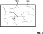
1 eine schematische Seitenansicht eines Patienten und eines Systems zur robotergestützten Chirurgie mit einem Manipulator, der vier Manipulatorarme hat, mit denen jeweils eine Instrumenteneinheit verbindbar ist;2 eine schematische Vorderansicht des Patienten und desSystems nach 1 ;3 einen Ausschnitt des Patienten und des Systems nachden 1 und2 ;4 ein auf einer Anzeigeeinheit als Bild dargestelltes Sichtfeld zusammen mit einem außerhalb des Sichtfeldes befindlichen Instrument;5 ein auf einer Anzeigeeinheit als Bild dargestelltes Sichtfeld bei der Markierung eines Bezugspunktes; und6 ein auf einer Anzeigeeinheit als Bild dargestelltes Sichtfeld zusammen mit einem außerhalb des Sichtfeldes befindlichen Bezugspunkt.
1 a schematic side view of a patient and a system for robotic surgery with a manipulator having four manipulator arms, with each of which an instrument unit is connectable;2 a schematic front view of the patient and the system according to1 ;3 a section of the patient and the system after the1 and2 ;4 a field of view displayed on a display unit as an image along with an out-of-field instrument;5 a visual field displayed on a display unit as an image when marking a reference point; and6 an image displayed on a display unit as an image field of view together with an out of the field of view reference point.
Der Operationstisch
Die Oberfläche der Patientenlagerfläche
Die Koordinaten x'z, y'z, z'z des Operationsgebiets
Mit Hilfe der durch das Operationsgebiet
Der Endeffektor 310 der Instrumenteneinheit
Der in die Körperöffnung des Patienten
Das Endoskop
Somit ist mithilfe des dargestellten Pfeils
Ist das Endoskop
Durch die in Verbindung mit den
Die Manipulatorarme
Auch die Lage und Orientierung des Sichtfelds bzw. der Objektebene
Im Falle einer visuellen Informationsausgabe kann die Darstellung der Information beispielsweise durch das Anheften eines Vektorpfeils an den im Bild
Bei alternativen Ausführungsbeispielen können auch mehrere Bezugspunkte festgelegt sein, so dass dann mehrere Vektorpfeile
Die Länge des dargestellten Vektorpfeils
Im Falle einer haptischen Informationsausgabe kann die Rückmeldung an den Chirurgen durch die Erzeugung von Kräften auf Eingabeelemente eines haptischen Eingabegeräts derart erfolgen, dass eine Bewegung des Endoskops
BezugszeichenlisteLIST OF REFERENCE NUMBERS
- 1010
- Systemsystem
- 1212
- Manipulatormanipulator
- 1414
- Stativtripod
- 16a bis 16d16a to 16d
- Manipulatorarmmanipulator
- 17a, 17b17a, 17b
- Trokar-HalterungTrocar holder
- 1818
- Patientpatient
- 19a, 19b19a, 19b
- Trokartrocar
- 2020
- Stativkopftripod head
- 2424
- Stativfußstand base
- 2626
- Traversetraverse
- 2828
- Stativarmstand arm
- 3030
- ZieloperationsgebietTarget area of operations
- 3131
- Mittelpunkt des ZieloperationsgebietCenter of the target surgical area
- 3232
- OperationstischsäuleOperating table column
- 3434
- Operationstischoperating table
- 36 36
- Steuereinheit des OperationstischesControl unit of the operating table
- 3838
- PatientenlagerflächePatient support surface
- 4040
- zentrale Steuereinheit der Vorrichtungcentral control unit of the device
- 4141
- Ausgabeeinheitoutput unit
- 4242
- Bedienkonsoleoperator
- 4444
- Anzeigeeinheitdisplay unit
- 4646
- Steuereinheit des ManipulatorsControl unit of the manipulator
- 4747
- Ausgabeeinheitoutput unit
- 100, 100a bis 100d100, 100a to 100d
- Koppeleinheitcoupling unit
- 300, 300c, 300d, 308, 312300, 300c, 300d, 308, 312
- Instrumenteneinheitinstrument unit
- 309309
- Instrumentenschaftinstrument shaft
- 314314
- Endoskopschaftendoscope shaft
- 308308
- Endeffektorend effector
- 316316
- optische Achseoptical axis
- 303b303b
- Schnittpunktintersection
- 304b304b
- Objektebeneobject level
- 312312
- Endoskopendoscope
- 1200, 1300, 14001200, 1300, 1400
- angezeigtes Bilddisplayed image
- 1220, 12401220, 1240
- Bezugspunktreference point
- 1250, 14501250, 1450
- Vektorpfeilvector arrow
- 1260, 14601260, 1460
- Zahlenwertvalue
- P1P1
- Richtungspfeilarrow
- X, Y, ZX, Y, Z
- Koordinatensystem der VorrichtungCoordinate system of the device
- X', Y', Z'X ', Y', Z '
- PatientenkoordinatensystemPatient coordinate system
ZITATE ENTHALTEN IN DER BESCHREIBUNG QUOTES INCLUDE IN THE DESCRIPTION
Diese Liste der vom Anmelder aufgeführten Dokumente wurde automatisiert erzeugt und ist ausschließlich zur besseren Information des Lesers aufgenommen. Die Liste ist nicht Bestandteil der deutschen Patent- bzw. Gebrauchsmusteranmeldung. Das DPMA übernimmt keinerlei Haftung für etwaige Fehler oder Auslassungen.This list of the documents listed by the applicant has been generated automatically and is included solely for the better information of the reader. The list is not part of the German patent or utility model application. The DPMA assumes no liability for any errors or omissions.
Zitierte PatentliteraturCited patent literature
- DE 102015109368 [0003]DE 102015109368 [0003]
- DE 102015109371 [0003]DE 102015109371 [0003]
- EP 2411966 B1 [0006]EP 2411966 B1 [0006]
- EP 2046538 B1 [0007]EP 2046538 B1 [0007]
Claims (19)
Translated fromGermanPriority Applications (5)
| Application Number | Priority Date | Filing Date | Title |
|---|---|---|---|
| DE102017103198.7ADE102017103198A1 (en) | 2017-02-16 | 2017-02-16 | Device for determining and retrieving a reference point during a surgical procedure |
| EP18156280.2AEP3363358B1 (en) | 2017-02-16 | 2018-02-12 | Device for determining and retrieving a reference point during a surgical operation |
| CN201810151576.6ACN108433809B (en) | 2017-02-16 | 2018-02-14 | Device for setting and retrieving a reference point during a surgical procedure |
| US15/897,501US10881268B2 (en) | 2017-02-16 | 2018-02-15 | Device to set and retrieve a reference point during a surgical procedure |
| HK18116635.7AHK1257424B (en) | 2017-02-16 | 2018-12-27 | Device to set and retrieve a reference point during a surgical procedure |
Applications Claiming Priority (1)
| Application Number | Priority Date | Filing Date | Title |
|---|---|---|---|
| DE102017103198.7ADE102017103198A1 (en) | 2017-02-16 | 2017-02-16 | Device for determining and retrieving a reference point during a surgical procedure |
Publications (1)
| Publication Number | Publication Date |
|---|---|
| DE102017103198A1true DE102017103198A1 (en) | 2018-08-16 |
Family
ID=61192783
Family Applications (1)
| Application Number | Title | Priority Date | Filing Date |
|---|---|---|---|
| DE102017103198.7AWithdrawnDE102017103198A1 (en) | 2017-02-16 | 2017-02-16 | Device for determining and retrieving a reference point during a surgical procedure |
Country Status (4)
| Country | Link |
|---|---|
| US (1) | US10881268B2 (en) |
| EP (1) | EP3363358B1 (en) |
| CN (1) | CN108433809B (en) |
| DE (1) | DE102017103198A1 (en) |
Cited By (1)
| Publication number | Priority date | Publication date | Assignee | Title |
|---|---|---|---|---|
| DE102023129189A1 (en)* | 2023-10-24 | 2025-04-24 | Karl Storz Se & Co. Kg | Medical imaging method and medical imaging system |
Families Citing this family (13)
| Publication number | Priority date | Publication date | Assignee | Title |
|---|---|---|---|---|
| CN107049492B (en)* | 2017-05-26 | 2020-02-21 | 微创(上海)医疗机器人有限公司 | Surgical robot system and method for displaying position of surgical instrument |
| WO2019006028A1 (en)* | 2017-06-28 | 2019-01-03 | Intuitive Surgical Operations, Inc. | Systems and methods for projecting an endoscopic image to a three-dimensional volume |
| WO2019023390A2 (en) | 2017-07-27 | 2019-01-31 | Intuitive Surgical Operations, Inc. | Medical device handle |
| US10610310B2 (en)* | 2017-10-02 | 2020-04-07 | Robin Elizabeth McKenzie TODD | User interface system and methods for overlaying surgical video output |
| JP7093833B2 (en)* | 2018-04-26 | 2022-06-30 | オリンパス株式会社 | Mobility support system and mobility support method |
| GB2612245B (en)* | 2018-10-03 | 2023-08-30 | Cmr Surgical Ltd | Automatic endoscope video augmentation |
| US12402963B2 (en)* | 2019-07-31 | 2025-09-02 | Auris Health, Inc. | Apparatus, systems, and methods to facilitate instrument visualization |
| JP6754150B1 (en)* | 2020-02-12 | 2020-09-09 | リバーフィールド株式会社 | Surgical robot |
| US20210267692A1 (en)* | 2020-02-28 | 2021-09-02 | Covidien Lp | Systems and methods for performing robotic surgery |
| CN116685285A (en)* | 2020-11-30 | 2023-09-01 | 直观外科手术操作公司 | System for providing a composite indicator in a user interface of a robot-assisted system |
| CN112971996B (en)* | 2021-02-03 | 2023-02-10 | 上海微创医疗机器人(集团)股份有限公司 | Computer-readable storage medium, electronic device, and surgical robot system |
| US12075984B2 (en)* | 2021-07-14 | 2024-09-03 | Cilag Gmbh International | Stereoscopic endoscope with critical structure depth estimation |
| US20230346199A1 (en)* | 2022-04-29 | 2023-11-02 | 3Dintegrated Aps | Anatomy measurement |
Citations (4)
| Publication number | Priority date | Publication date | Assignee | Title |
|---|---|---|---|---|
| DE3738667A1 (en) | 1986-11-13 | 1988-05-26 | Olympus Optical Co | METHOD FOR PROCESSING ENDOSCOPIC IMAGES |
| DE69322202T2 (en) | 1992-05-27 | 1999-07-01 | International Business Machines Corp., Armonk, N.Y. | System and method for improving endoscopic surgery |
| DE102012211396A1 (en) | 2012-07-02 | 2014-04-24 | Technische Universität Berlin | Endoscopic device for taking picture within blood vessel cavity of human, calculates distance between image pickup unit, striking landmark and distinctive landmark based on performed movement of image recording device |
| DE102015109371A1 (en) | 2015-06-12 | 2016-12-15 | avateramedical GmBH | Apparatus and method for robotic surgery |
Family Cites Families (26)
| Publication number | Priority date | Publication date | Assignee | Title |
|---|---|---|---|---|
| US6702736B2 (en)* | 1995-07-24 | 2004-03-09 | David T. Chen | Anatomical visualization system |
| JPH09149876A (en)* | 1995-11-30 | 1997-06-10 | Olympus Optical Co Ltd | Endoscope device |
| DE10033723C1 (en)* | 2000-07-12 | 2002-02-21 | Siemens Ag | Surgical instrument position and orientation visualization device for surgical operation has data representing instrument position and orientation projected onto surface of patient's body |
| EP1365686A4 (en)* | 2000-09-23 | 2009-12-02 | Ramin Shahidi | Endoscopic targeting method and system |
| EP2316328B1 (en)* | 2003-09-15 | 2012-05-09 | Super Dimension Ltd. | Wrap-around holding device for use with bronchoscopes |
| JP2005224528A (en)* | 2004-02-16 | 2005-08-25 | Olympus Corp | Endoscope |
| US8073528B2 (en)* | 2007-09-30 | 2011-12-06 | Intuitive Surgical Operations, Inc. | Tool tracking systems, methods and computer products for image guided surgery |
| JP4999012B2 (en)* | 2005-06-06 | 2012-08-15 | インチュイティブ サージカル,インコーポレイテッド | Laparoscopic ultrasonic robotic surgical system |
| US9718190B2 (en)* | 2006-06-29 | 2017-08-01 | Intuitive Surgical Operations, Inc. | Tool position and identification indicator displayed in a boundary area of a computer display screen |
| US8496575B2 (en)* | 2006-11-14 | 2013-07-30 | Olympus Corporation | Measuring endoscope apparatus, program and recording medium |
| US10004387B2 (en)* | 2009-03-26 | 2018-06-26 | Intuitive Surgical Operations, Inc. | Method and system for assisting an operator in endoscopic navigation |
| KR101903307B1 (en)* | 2009-03-26 | 2018-10-01 | 인튜어티브 서지컬 오퍼레이션즈 인코포레이티드 | System for providing visual guidance for steering a tip of an endoscopic device towards one or more landmarks and assisting an operator in endoscopic navigation |
| US9155592B2 (en)* | 2009-06-16 | 2015-10-13 | Intuitive Surgical Operations, Inc. | Virtual measurement tool for minimally invasive surgery |
| JP5724396B2 (en)* | 2011-01-13 | 2015-05-27 | ソニー株式会社 | Map display control device, map display control method, and program |
| DE112012000752A5 (en)* | 2011-02-11 | 2013-11-21 | Olaf Christiansen | Endoscopic image processing system with means which generate geometric survey information in the detection area of an optical digital camera |
| WO2015049962A1 (en)* | 2013-10-02 | 2015-04-09 | オリンパスメディカルシステムズ株式会社 | Endoscope system |
| JP6049202B2 (en)* | 2013-10-25 | 2016-12-21 | 富士フイルム株式会社 | Image processing apparatus, method, and program |
| WO2015149043A1 (en)* | 2014-03-28 | 2015-10-01 | Dorin Panescu | Quantitative three-dimensional imaging and printing of surgical implants |
| KR20150128049A (en)* | 2014-05-08 | 2015-11-18 | 삼성전자주식회사 | Surgical robot and control method thereof |
| US11351000B2 (en)* | 2014-07-28 | 2022-06-07 | Intuitive Surgical Operations, Inc. | Systems and methods for planning multiple interventional procedures |
| DE102014117408A1 (en) | 2014-11-27 | 2016-06-02 | avateramedical GmBH | Device for robotic surgery |
| WO2016199273A1 (en)* | 2015-06-11 | 2016-12-15 | オリンパス株式会社 | Endoscope device and operation method for endoscope device |
| DE102015109368A1 (en) | 2015-06-12 | 2016-12-15 | avateramedical GmBH | Device and method for robotic surgery and positioning aid |
| DE112015006617T5 (en)* | 2015-07-08 | 2018-03-08 | Olympus Corporation | endoscopic device |
| DE102016109173A1 (en)* | 2015-11-19 | 2017-05-24 | Aesculap Ag | Medical-technical coordinate measuring device and medical-technical coordinate measuring method |
| WO2017109912A1 (en)* | 2015-12-24 | 2017-06-29 | オリンパス株式会社 | Medical manipulator system and image display method for same |
- 2017
- 2017-02-16DEDE102017103198.7Apatent/DE102017103198A1/ennot_activeWithdrawn
- 2018
- 2018-02-12EPEP18156280.2Apatent/EP3363358B1/enactiveActive
- 2018-02-14CNCN201810151576.6Apatent/CN108433809B/enactiveActive
- 2018-02-15USUS15/897,501patent/US10881268B2/ennot_activeExpired - Fee Related
Patent Citations (4)
| Publication number | Priority date | Publication date | Assignee | Title |
|---|---|---|---|---|
| DE3738667A1 (en) | 1986-11-13 | 1988-05-26 | Olympus Optical Co | METHOD FOR PROCESSING ENDOSCOPIC IMAGES |
| DE69322202T2 (en) | 1992-05-27 | 1999-07-01 | International Business Machines Corp., Armonk, N.Y. | System and method for improving endoscopic surgery |
| DE102012211396A1 (en) | 2012-07-02 | 2014-04-24 | Technische Universität Berlin | Endoscopic device for taking picture within blood vessel cavity of human, calculates distance between image pickup unit, striking landmark and distinctive landmark based on performed movement of image recording device |
| DE102015109371A1 (en) | 2015-06-12 | 2016-12-15 | avateramedical GmBH | Apparatus and method for robotic surgery |
Cited By (1)
| Publication number | Priority date | Publication date | Assignee | Title |
|---|---|---|---|---|
| DE102023129189A1 (en)* | 2023-10-24 | 2025-04-24 | Karl Storz Se & Co. Kg | Medical imaging method and medical imaging system |
Also Published As
| Publication number | Publication date |
|---|---|
| EP3363358A2 (en) | 2018-08-22 |
| EP3363358B1 (en) | 2020-10-21 |
| HK1257424A1 (en) | 2019-10-18 |
| CN108433809B (en) | 2023-06-13 |
| US10881268B2 (en) | 2021-01-05 |
| EP3363358A3 (en) | 2018-09-26 |
| CN108433809A (en) | 2018-08-24 |
| US20180228343A1 (en) | 2018-08-16 |
Similar Documents
| Publication | Publication Date | Title |
|---|---|---|
| EP3363358B1 (en) | Device for determining and retrieving a reference point during a surgical operation | |
| DE69322202T2 (en) | System and method for improving endoscopic surgery | |
| EP2575662B1 (en) | Method for moving an instrument arm of a laparoscopy robot into a predeterminable relative position with respect to a trocar | |
| EP2449997B1 (en) | Medical workstation | |
| EP0975257B1 (en) | Endoscopic system | |
| WO2008058520A2 (en) | Apparatus for supplying images to an operator | |
| EP4213755B1 (en) | Surgical assistance system | |
| WO2001089405A1 (en) | Fully-automatic, robot-assisted camera guidance using position sensors for laparoscopic interventions | |
| EP2672915A1 (en) | Endoscopic image processing system having means which generate geometric measurement information in the detection range of an optical digital camera | |
| DE102014210046A1 (en) | Surgical microscope system | |
| DE102014219477B4 (en) | Surgery robotic system | |
| DE102014210056A1 (en) | Method for controlling a surgical device and surgical device | |
| DE102010042372A1 (en) | Method for creating a medical image and medical workstation | |
| WO2023247444A1 (en) | Laser-guidance robot for visually projecting a guide to a surgery plan, projection method, and laser-guidance robot system | |
| DE102004052753A1 (en) | Electromagnetic navigation system for coordination of minimal invasive operation, comprising two exterior sensor elements | |
| DE10235795A1 (en) | Medical device | |
| DE102020126029A1 (en) | Surgical assistance system and display method | |
| DE4204601B4 (en) | Device for detecting position information with an optical observation unit and method for determining position information | |
| EP4208750B1 (en) | Method for operating a microscopy system, and microscopy system | |
| EP1537830B1 (en) | Method and device for viewing an object with a microscope | |
| WO2024170384A1 (en) | Medical robot with different end effectors, robotic system and control method for a medical robot | |
| WO2021058727A1 (en) | Device for navigating a medical instrument relative to a patient anatomy | |
| DE102022118990A1 (en) | Navigation system and navigation method with annotation function | |
| WO2024018011A1 (en) | Control device and system, and system having a medical operation instrument, a data capture device and a data processing apparatus | |
| EP4622580A1 (en) | Assistance system, computer-implemented control method, and computer-readable storage medium |
Legal Events
| Date | Code | Title | Description |
|---|---|---|---|
| R163 | Identified publications notified | ||
| R119 | Application deemed withdrawn, or ip right lapsed, due to non-payment of renewal fee |