DE102017102828A1 - Catheter pump with a pump head for insertion into the arterial vasculature - Google Patents
Catheter pump with a pump head for insertion into the arterial vasculatureDownload PDFInfo
- Publication number
- DE102017102828A1 DE102017102828A1DE102017102828.5ADE102017102828ADE102017102828A1DE 102017102828 A1DE102017102828 A1DE 102017102828A1DE 102017102828 ADE102017102828 ADE 102017102828ADE 102017102828 A1DE102017102828 A1DE 102017102828A1
- Authority
- DE
- Germany
- Prior art keywords
- bearing
- catheter
- pump
- proximal
- sleeve
- Prior art date
- Legal status (The legal status is an assumption and is not a legal conclusion. Google has not performed a legal analysis and makes no representation as to the accuracy of the status listed.)
- Ceased
Links
- 210000005249arterial vasculatureAnatomy0.000titleclaims2
- 230000037431insertionEffects0.000titledescription2
- 238000003780insertionMethods0.000titledescription2
- 230000002792vascularEffects0.000claimsabstractdescription3
- 239000012530fluidSubstances0.000claimsdescription14
- 125000006850spacer groupChemical group0.000claimsdescription11
- 239000007788liquidSubstances0.000claimsdescription10
- 210000000709aortaAnatomy0.000description8
- 238000011010flushing procedureMethods0.000description8
- 238000005461lubricationMethods0.000description2
- BUHVIAUBTBOHAG-FOYDDCNASA-N(2r,3r,4s,5r)-2-[6-[[2-(3,5-dimethoxyphenyl)-2-(2-methylphenyl)ethyl]amino]purin-9-yl]-5-(hydroxymethyl)oxolane-3,4-diolChemical compoundCOC1=CC(OC)=CC(C(CNC=2C=3N=CN(C=3N=CN=2)[C@H]2[C@@H]([C@H](O)[C@@H](CO)O2)O)C=2C(=CC=CC=2)C)=C1BUHVIAUBTBOHAG-FOYDDCNASA-N0.000description1
- 239000008280bloodSubstances0.000description1
- 210000004369bloodAnatomy0.000description1
- 238000010276constructionMethods0.000description1
- 230000008878couplingEffects0.000description1
- 238000010168coupling processMethods0.000description1
- 238000005859coupling reactionMethods0.000description1
- 238000006073displacement reactionMethods0.000description1
- 238000001356surgical procedureMethods0.000description1
Images

Classifications
- A—HUMAN NECESSITIES
- A61—MEDICAL OR VETERINARY SCIENCE; HYGIENE
- A61M—DEVICES FOR INTRODUCING MEDIA INTO, OR ONTO, THE BODY; DEVICES FOR TRANSDUCING BODY MEDIA OR FOR TAKING MEDIA FROM THE BODY; DEVICES FOR PRODUCING OR ENDING SLEEP OR STUPOR
- A61M60/00—Blood pumps; Devices for mechanical circulatory actuation; Balloon pumps for circulatory assistance
- A61M60/10—Location thereof with respect to the patient's body
- A61M60/122—Implantable pumps or pumping devices, i.e. the blood being pumped inside the patient's body
- A61M60/126—Implantable pumps or pumping devices, i.e. the blood being pumped inside the patient's body implantable via, into, inside, in line, branching on, or around a blood vessel
- A61M60/135—Implantable pumps or pumping devices, i.e. the blood being pumped inside the patient's body implantable via, into, inside, in line, branching on, or around a blood vessel inside a blood vessel, e.g. using grafting
- A—HUMAN NECESSITIES
- A61—MEDICAL OR VETERINARY SCIENCE; HYGIENE
- A61M—DEVICES FOR INTRODUCING MEDIA INTO, OR ONTO, THE BODY; DEVICES FOR TRANSDUCING BODY MEDIA OR FOR TAKING MEDIA FROM THE BODY; DEVICES FOR PRODUCING OR ENDING SLEEP OR STUPOR
- A61M60/00—Blood pumps; Devices for mechanical circulatory actuation; Balloon pumps for circulatory assistance
- A61M60/10—Location thereof with respect to the patient's body
- A61M60/122—Implantable pumps or pumping devices, i.e. the blood being pumped inside the patient's body
- A61M60/126—Implantable pumps or pumping devices, i.e. the blood being pumped inside the patient's body implantable via, into, inside, in line, branching on, or around a blood vessel
- A61M60/13—Implantable pumps or pumping devices, i.e. the blood being pumped inside the patient's body implantable via, into, inside, in line, branching on, or around a blood vessel by means of a catheter allowing explantation, e.g. catheter pumps temporarily introduced via the vascular system
- A—HUMAN NECESSITIES
- A61—MEDICAL OR VETERINARY SCIENCE; HYGIENE
- A61M—DEVICES FOR INTRODUCING MEDIA INTO, OR ONTO, THE BODY; DEVICES FOR TRANSDUCING BODY MEDIA OR FOR TAKING MEDIA FROM THE BODY; DEVICES FOR PRODUCING OR ENDING SLEEP OR STUPOR
- A61M60/00—Blood pumps; Devices for mechanical circulatory actuation; Balloon pumps for circulatory assistance
- A61M60/10—Location thereof with respect to the patient's body
- A61M60/122—Implantable pumps or pumping devices, i.e. the blood being pumped inside the patient's body
- A61M60/126—Implantable pumps or pumping devices, i.e. the blood being pumped inside the patient's body implantable via, into, inside, in line, branching on, or around a blood vessel
- A61M60/135—Implantable pumps or pumping devices, i.e. the blood being pumped inside the patient's body implantable via, into, inside, in line, branching on, or around a blood vessel inside a blood vessel, e.g. using grafting
- A61M60/139—Implantable pumps or pumping devices, i.e. the blood being pumped inside the patient's body implantable via, into, inside, in line, branching on, or around a blood vessel inside a blood vessel, e.g. using grafting inside the aorta, e.g. intra-aortic balloon pumps
- A—HUMAN NECESSITIES
- A61—MEDICAL OR VETERINARY SCIENCE; HYGIENE
- A61M—DEVICES FOR INTRODUCING MEDIA INTO, OR ONTO, THE BODY; DEVICES FOR TRANSDUCING BODY MEDIA OR FOR TAKING MEDIA FROM THE BODY; DEVICES FOR PRODUCING OR ENDING SLEEP OR STUPOR
- A61M60/00—Blood pumps; Devices for mechanical circulatory actuation; Balloon pumps for circulatory assistance
- A61M60/10—Location thereof with respect to the patient's body
- A61M60/122—Implantable pumps or pumping devices, i.e. the blood being pumped inside the patient's body
- A61M60/126—Implantable pumps or pumping devices, i.e. the blood being pumped inside the patient's body implantable via, into, inside, in line, branching on, or around a blood vessel
- A61M60/148—Implantable pumps or pumping devices, i.e. the blood being pumped inside the patient's body implantable via, into, inside, in line, branching on, or around a blood vessel in line with a blood vessel using resection or like techniques, e.g. permanent endovascular heart assist devices
- A—HUMAN NECESSITIES
- A61—MEDICAL OR VETERINARY SCIENCE; HYGIENE
- A61M—DEVICES FOR INTRODUCING MEDIA INTO, OR ONTO, THE BODY; DEVICES FOR TRANSDUCING BODY MEDIA OR FOR TAKING MEDIA FROM THE BODY; DEVICES FOR PRODUCING OR ENDING SLEEP OR STUPOR
- A61M60/00—Blood pumps; Devices for mechanical circulatory actuation; Balloon pumps for circulatory assistance
- A61M60/20—Type thereof
- A61M60/205—Non-positive displacement blood pumps
- A61M60/216—Non-positive displacement blood pumps including a rotating member acting on the blood, e.g. impeller
- A61M60/237—Non-positive displacement blood pumps including a rotating member acting on the blood, e.g. impeller the blood flow through the rotating member having mainly axial components, e.g. axial flow pumps
- A—HUMAN NECESSITIES
- A61—MEDICAL OR VETERINARY SCIENCE; HYGIENE
- A61M—DEVICES FOR INTRODUCING MEDIA INTO, OR ONTO, THE BODY; DEVICES FOR TRANSDUCING BODY MEDIA OR FOR TAKING MEDIA FROM THE BODY; DEVICES FOR PRODUCING OR ENDING SLEEP OR STUPOR
- A61M60/00—Blood pumps; Devices for mechanical circulatory actuation; Balloon pumps for circulatory assistance
- A61M60/30—Medical purposes thereof other than the enhancement of the cardiac output
- A61M60/36—Medical purposes thereof other than the enhancement of the cardiac output for specific blood treatment; for specific therapy
- A61M60/38—Blood oxygenation
- A—HUMAN NECESSITIES
- A61—MEDICAL OR VETERINARY SCIENCE; HYGIENE
- A61M—DEVICES FOR INTRODUCING MEDIA INTO, OR ONTO, THE BODY; DEVICES FOR TRANSDUCING BODY MEDIA OR FOR TAKING MEDIA FROM THE BODY; DEVICES FOR PRODUCING OR ENDING SLEEP OR STUPOR
- A61M60/00—Blood pumps; Devices for mechanical circulatory actuation; Balloon pumps for circulatory assistance
- A61M60/40—Details relating to driving
- A61M60/403—Details relating to driving for non-positive displacement blood pumps
- A61M60/408—Details relating to driving for non-positive displacement blood pumps the force acting on the blood contacting member being mechanical, e.g. transmitted by a shaft or cable
- A—HUMAN NECESSITIES
- A61—MEDICAL OR VETERINARY SCIENCE; HYGIENE
- A61M—DEVICES FOR INTRODUCING MEDIA INTO, OR ONTO, THE BODY; DEVICES FOR TRANSDUCING BODY MEDIA OR FOR TAKING MEDIA FROM THE BODY; DEVICES FOR PRODUCING OR ENDING SLEEP OR STUPOR
- A61M60/00—Blood pumps; Devices for mechanical circulatory actuation; Balloon pumps for circulatory assistance
- A61M60/80—Constructional details other than related to driving
- A61M60/802—Constructional details other than related to driving of non-positive displacement blood pumps
- A61M60/804—Impellers
- A61M60/806—Vanes or blades
- A61M60/808—Vanes or blades specially adapted for deformable impellers, e.g. expandable impellers
- A—HUMAN NECESSITIES
- A61—MEDICAL OR VETERINARY SCIENCE; HYGIENE
- A61M—DEVICES FOR INTRODUCING MEDIA INTO, OR ONTO, THE BODY; DEVICES FOR TRANSDUCING BODY MEDIA OR FOR TAKING MEDIA FROM THE BODY; DEVICES FOR PRODUCING OR ENDING SLEEP OR STUPOR
- A61M60/00—Blood pumps; Devices for mechanical circulatory actuation; Balloon pumps for circulatory assistance
- A61M60/80—Constructional details other than related to driving
- A61M60/802—Constructional details other than related to driving of non-positive displacement blood pumps
- A61M60/818—Bearings
- A61M60/825—Contact bearings, e.g. ball-and-cup or pivot bearings
- A—HUMAN NECESSITIES
- A61—MEDICAL OR VETERINARY SCIENCE; HYGIENE
- A61M—DEVICES FOR INTRODUCING MEDIA INTO, OR ONTO, THE BODY; DEVICES FOR TRANSDUCING BODY MEDIA OR FOR TAKING MEDIA FROM THE BODY; DEVICES FOR PRODUCING OR ENDING SLEEP OR STUPOR
- A61M60/00—Blood pumps; Devices for mechanical circulatory actuation; Balloon pumps for circulatory assistance
- A61M60/80—Constructional details other than related to driving
- A61M60/855—Constructional details other than related to driving of implantable pumps or pumping devices
- A61M60/857—Implantable blood tubes
- A61M60/859—Connections therefor
- A—HUMAN NECESSITIES
- A61—MEDICAL OR VETERINARY SCIENCE; HYGIENE
- A61M—DEVICES FOR INTRODUCING MEDIA INTO, OR ONTO, THE BODY; DEVICES FOR TRANSDUCING BODY MEDIA OR FOR TAKING MEDIA FROM THE BODY; DEVICES FOR PRODUCING OR ENDING SLEEP OR STUPOR
- A61M60/00—Blood pumps; Devices for mechanical circulatory actuation; Balloon pumps for circulatory assistance
- A61M60/80—Constructional details other than related to driving
- A61M60/855—Constructional details other than related to driving of implantable pumps or pumping devices
- A61M60/884—Constructional details other than related to driving of implantable pumps or pumping devices being associated to additional implantable blood treating devices
- A61M60/886—Blood oxygenators
- F—MECHANICAL ENGINEERING; LIGHTING; HEATING; WEAPONS; BLASTING
- F04—POSITIVE - DISPLACEMENT MACHINES FOR LIQUIDS; PUMPS FOR LIQUIDS OR ELASTIC FLUIDS
- F04D—NON-POSITIVE-DISPLACEMENT PUMPS
- F04D29/00—Details, component parts, or accessories
- F04D29/04—Shafts or bearings, or assemblies thereof
- F04D29/046—Bearings
- A—HUMAN NECESSITIES
- A61—MEDICAL OR VETERINARY SCIENCE; HYGIENE
- A61M—DEVICES FOR INTRODUCING MEDIA INTO, OR ONTO, THE BODY; DEVICES FOR TRANSDUCING BODY MEDIA OR FOR TAKING MEDIA FROM THE BODY; DEVICES FOR PRODUCING OR ENDING SLEEP OR STUPOR
- A61M2210/00—Anatomical parts of the body
- A61M2210/12—Blood circulatory system
- A61M2210/125—Heart
- A—HUMAN NECESSITIES
- A61—MEDICAL OR VETERINARY SCIENCE; HYGIENE
- A61M—DEVICES FOR INTRODUCING MEDIA INTO, OR ONTO, THE BODY; DEVICES FOR TRANSDUCING BODY MEDIA OR FOR TAKING MEDIA FROM THE BODY; DEVICES FOR PRODUCING OR ENDING SLEEP OR STUPOR
- A61M2210/00—Anatomical parts of the body
- A61M2210/12—Blood circulatory system
- A61M2210/127—Aorta
Landscapes
- Health & Medical Sciences (AREA)
- Heart & Thoracic Surgery (AREA)
- Engineering & Computer Science (AREA)
- Cardiology (AREA)
- Mechanical Engineering (AREA)
- Biomedical Technology (AREA)
- Anesthesiology (AREA)
- Hematology (AREA)
- Life Sciences & Earth Sciences (AREA)
- Animal Behavior & Ethology (AREA)
- General Health & Medical Sciences (AREA)
- Public Health (AREA)
- Veterinary Medicine (AREA)
- Vascular Medicine (AREA)
- Emergency Medicine (AREA)
- Transplantation (AREA)
- General Engineering & Computer Science (AREA)
- External Artificial Organs (AREA)
Abstract
Translated fromGerman
Description
Translated fromGermanDie Erfindung betrifft eine Katheterpumpe mit einem Pumpenkopf zum Einführen in das arterielle Gefäßsystem wie zum Beispiel die Aorta oder das Herz, mit einem Außenkatheter, einen im Außenkatheter angeordneten Innenkatheter und einer im Innenkatheter verdrehbar angeordneten Rotorwelle zum Antreiben eines am Pumpenkopf vorgesehen, expandierbaren Förderelements, wobei das Förderelement zwischen einer distalen Lagerstelle und einer proximalen Lagerstelle drehgelagert ist, wobei der Außenkatheter an seinem distale Ende einen die proximale Lagerstelle umgebenden Hülsenabschnitt aufweist, und wobei die proximale Lagerstelle zum Expandieren des Förderelements relativ zum Hülsenabschnitt in axialer Richtung bewegbar ist.The invention relates to a catheter pump with a pump head for introduction into the arterial vascular system such as the aorta or the heart, with an outer catheter, an inner catheter disposed in the outer catheter and a rotatable inner catheter rotatably arranged rotor shaft for driving a provided on the pump head, expandable conveying element the conveying element is rotatably mounted between a distal bearing location and a proximal bearing location, the outer catheter having at its distal end a sleeve portion surrounding the proximal bearing location, and wherein the proximal bearing location for expanding the conveying element is movable relative to the sleeve portion in the axial direction.
Derartige Katheterpumpen sind beispielsweise aus der
Katheterpumpen werden als temporäres Kreislaufunterstützungssystem in die Aorta von Patienten eingesetzt, insbesondere dann, wenn das natürliche Herz nicht in der Lage ist, den Körper mit ausreichend Sauerstoff versetztem Blut zu versorgen. Das Förderelement und die Rotorwelle werden dabei mit vergleichsweise hohen Drehzahlen im Bereich von 7000 bis 15000 Drehungen pro Minute betrieben. Der Pumpenkopf der Katheterpumpe kann insbesondere nach einer Operation mehrere Tage in der Aorta verbleiben.Catheter pumps are used as a temporary circulatory support system in the aorta of patients, especially when the natural heart is unable to provide the body with sufficient oxygenated blood. The conveying element and the rotor shaft are operated at comparatively high speeds in the range of 7,000 to 15,000 rotations per minute. The pump head of the catheter pump can remain in the aorta for several days, especially after surgery.
Der vorliegenden Erfindung liegt die Aufgabe zugrunde, die proximale Lagerstelle der eingangs genannten Katheterpumpe vorteilhaft auszubilden.The present invention has for its object to form the proximal bearing point of the aforementioned catheter pump advantageous.
Diese Aufgabe wird durch eine Katheterpumpe mit den Merkmalen des Patentanspruchs 1 gelöst. Die Erfindung sieht folglich vor, dass die proximale Lagerstelle, also die Lagerstelle, die in axialer Richtung zwischen den Kathetern und der anderen, distalen Lagerstelle liegt, eine Lageraufnahme umfasst, die eine Drehlagerstelle für einen mit dem distalen Ende der Rotorwelle drehfest verbundenen Drehkopf und eine dazu axial beabstandete Krafteinleitstelle für einen am distalen Ende des Innenkatheters vorgesehenen Krafteinleitabschnitt zum axialen Bewegen der proximalen Lagerstelle relativ zum Hülsenabschnitt aufweist. Durch Vorsehen einer solchen Lageraufnahme, die die Drehlagerstelle und die Krafteinleitstelle aufweist, können mehrere Funktionen in einem Bauteil auf kleinstem Bauraum realisiert werden. Zum einen kann das Förderelement, und insbesondere ein Rotor des Förderelements, in der Drehlagerstelle drehsicher gelagert werden. Zum anderen kann aufgrund des Vorsehens der Krafteinleitstelle an der Lageraufnahme eine Relativbewegung zwischen dem Hülsenabschnitt des Außenkatheders und der Lageraufnahme zum Expandieren des Förderelements funktionssicher erfolgen.This object is achieved by a catheter pump having the features of patent claim 1. The invention therefore provides that the proximal bearing point, ie the bearing point which lies in the axial direction between the catheters and the other distal bearing point, comprises a bearing receptacle which has a pivot bearing point for a rotatably connected to the distal end of the rotor shaft turret and a for axially spaced force introduction point for a provided at the distal end of the inner catheter force introduction section for axially moving the proximal bearing point relative to the sleeve portion. By providing such a bearing receptacle, which has the pivot bearing point and the force introduction point, several functions can be realized in a component in the smallest space. On the one hand, the conveying element, and in particular a rotor of the conveying element, can be mounted in a rotationally secure manner in the pivot bearing position. On the other hand, a relative movement between the sleeve section of the outer catheter and the bearing receptacle for expanding the conveying element can be functionally reliable due to the provision of the force introduction point on the bearing receptacle.
Der Hülsenabschnitt kann dabei einstückig am Außenkatheter angeordnet sein oder von diesem gebildet werden. Ferner ist denkbar, dass der Hülsenabschnitt als separates Bauteil ausgebildet sein kann, das fest mit dem Außenkatheter verbunden ist.The sleeve section can be arranged integrally on the outer catheter or be formed by this. It is also conceivable that the sleeve portion may be formed as a separate component which is firmly connected to the outer catheter.
Zum Kontrahieren oder Einklappen des Förderelements wird der Hülsenabschnitt relativ zur proximalen Lagerstelle in axialer Richtung weg von der distalen Lagerstelle bewegt.For contracting or folding in of the conveying element, the sleeve section is moved relative to the proximal bearing point in the axial direction away from the distal bearing point.
Vorteilhafterweise ist die Lageraufnahme hülsenartig ausgebildet. Dabei werden die Drehlagerstelle von einer ersten Innennut und die Krafteinleitstelle von einer zweiten Innennut gebildet. Insgesamt kann dadurch eine vergleichsweise einfach aufgebaute Lageraufnahme mit der Drehlagerstelle und der Krafteinleitstelle gebildet werden. Die erste Innennut kann dabei vergleichsweise flach ausgebildete Anfasungen aufweisen, so dass der Drehkopf entsprechend günstig gelagert werden kann. Die zweite Innennut kann dabei insbesondere so ausgebildet werden, dass ein als Ringbund ausgebildeter Krafteinleitabschnitt funktionssicher von der zweiten Innennut aufgenommen werden kann.Advantageously, the bearing receptacle is sleeve-shaped. The pivot bearing point are formed by a first inner groove and the force introduction point of a second inner groove. Overall, this allows a comparatively simple bearing mount with the pivot bearing point and the force introduction point are formed. The first inner groove can have comparatively flat chamfers, so that the rotary head can be stored appropriately low. In this case, the second inner groove can in particular be formed in such a way that a force introduction section formed as an annular collar can be reliably received by the second inner groove.
Eine besonders bevorzugte Ausführungsform sieht vor, dass die Lageraufnahme wenigstens zwei Lagerschalen umfasst. Beim Vorsehen von zwei Lagerschalen finden also zwei Halbschalen Verwendung. Die Verwendung von zwei oder mehr Lagerschalen hat den Vorteil, dass eine Montage der proximalen Lagerstelle auf einfache Art und Weise möglich ist.A particularly preferred embodiment provides that the bearing receptacle comprises at least two bearing shells. When providing two bearings so find two half shells use. The use of two or more bearing shells has the advantage that a mounting of the proximal bearing point in a simple manner is possible.
Dazu ist der Hülsenabschnitt vorteilhafterweise so ausgebildet, dass zur Montage der proximalen Lagerstelle zunächst die Lagerschalen in radialer Richtung auf den Drehkopf und auf den Krafteinleitabschnitt aufgesetzt werden und anschließend der Hülsenabschnitt in axialer Richtung über die Lagerschalen geschoben wird. Dies hat den Vorteil, dass weitere Montage- oder Befestigungsmittel entfallen können. Die Lagerschalen sind sicher im Hülsenabschnitt angeordnet.For this purpose, the sleeve portion is advantageously designed so that for mounting the proximal bearing initially the bearing shells are placed in the radial direction on the turret and the force introduction and then the sleeve portion is pushed in the axial direction on the bearing shells. This has the advantage that further assembly or fastening means can be omitted. The bearing shells are securely arranged in the sleeve section.
Die Lageraufnahme und insbesondere die Lagerschalen können vorzugsweise auf der dem Hülsenabschnitt zugewandten, radialen Außenseite Vertiefungen derart aufweisen, dass zwischen dem Innenkatheter und dem Außenkatheter hindurchströmende Spülflüssigkeit zwischen der Lageraufnahme, bzw. den Lagerschalen, und der Innenwandung des Hülsenabschnitts hindurchströmen kann. Die Vertiefungen sind dabei vorzugsweise als in axialer Richtung verlaufende Rillen in die Lageraufnahme bzw. die Lagerschalen eingeformt. Dadurch kann gewährleistet werden, dass Spülflüssigkeit, welche zwischen dem Außenkatheter und dem Innenkatheter hin zum Pumpenkopf gefördert wird, die proximale Lagerstelle passieren kann, ohne dass die Flüssigkeit die Drehlagerstelle passieren muss.The bearing receptacle and in particular the bearing shells can preferably have depressions on the radial outer side facing the sleeve section, such that flushing fluid flowing between the inner catheter and the outer catheter can pass between the bearing receptacle, or the bearing shells, and the inner wall of the sleeve portion can flow. The depressions are preferably formed as extending in the axial direction grooves in the bearing receptacle or the bearing shells. As a result, it can be ensured that rinsing fluid, which is conveyed between the outer catheter and the inner catheter towards the pump head, can pass through the proximal bearing location without the fluid having to pass through the rotary bearing position.
Ferner ist erfindungsgemäß denkbar, dass sich an das distale Ende der Lageraufnahme ein Stauraum anschließt, in dem sich im Betrieb Spülflüssigkeit sammelt und von dem aus die Spülflüssigkeit weiter zur distalen Lagerstelle, in die Aorta und/oder zurück durch den Innenkatheter geleitet wird. Hierdurch kann erreicht werden, dass zum einen auch die distale Lagerstelle mit entsprechender Spülflüssigkeit versorgt wird. Zum anderen kann ein Teil der Spülflüssigkeit, der im Bereich von einem Drittel der eingebrachten Spülflüssigkeit liegen kann, vorbei am Drehkopf durch die Drehlagerstelle hindurch zurück durch den Innenkatheter abgeführt werden. Dadurch kann erreicht werden, dass auch die Drehlagerstelle ausreichend mit entsprechender Spülflüssigkeit gespült und geschmiert werden kann. Die die Drehlagerstelle passierende Spülflüssigkeit wird also zurück durch den Innenkatheter bzw. durch ein Lumen zwischen dem Innenkatheter und der Rotorwelle geführt, so dass ein möglicher Lagerabrieb möglichst nicht in die Blutbahn des Patienten gelangt.Furthermore, it is conceivable according to the invention that a storage space adjoins the distal end of the bearing receptacle, in which flushing liquid collects during operation and from which the flushing liquid is passed on to the distal bearing point, into the aorta and / or back through the inner catheter. In this way, it can be achieved that, on the one hand, the distal bearing point is also supplied with appropriate rinsing fluid. On the other hand, a portion of the rinsing fluid, which may be in the range of one third of the introduced rinsing fluid, be discharged past the rotary head through the rotary bearing point back through the inner catheter. It can thereby be achieved that the rotary bearing point can also be sufficiently rinsed and lubricated with appropriate rinsing liquid. The rinsing fluid passing through the rotary bearing position is thus passed back through the inner catheter or through a lumen between the inner catheter and the rotor shaft, so that possible bearing wear does not reach the bloodstream of the patient as far as possible.
Der Krafteinleitabschnitt ist vorteilhafterweise an einer Buchse angeordnet, die fest am distalen Ende des Innenkatheters angeordnet ist. Die Buchse kann dabei den Innenkatheter in radialer Richtung umgeben. Der Krafteinleitabschnitt kann insbesondere als in radialer Richtung abstehender Ringbund ausgebildet sein, der in die zweite Innennut der Lageraufnahme eingreift. Hierdurch kann eine sichere in axialer Richtung wirkende Bewegungskopplung zwischen dem Innenkatheter bzw. der Buchse und der Lageraufnahme, bzw. der Lagerschalen, bereitgestellt werden.The force introduction section is advantageously arranged on a bush which is fixedly arranged on the distal end of the inner catheter. The bush can surround the inner catheter in the radial direction. The force introduction section can be designed, in particular, as an annular collar projecting in the radial direction, which engages in the second inner groove of the bearing receptacle. In this way, a secure coupling of movement acting in the axial direction between the inner catheter or the bushing and the bearing receptacle or of the bearing shells can be provided.
Die Buchse kann ihrerseits auf der der Drehlagerstelle abgewandten Seite einen zum Krafteinleitabschnitt beabstandeten Bundabschnitt aufweisen. Dieser Bundabschnitt kann als axialer Anschlag gegen den Außenkatheter, bzw. gegen eine zwischen der Buchse und dem Außenkatheter vorgesehene Distanzhülse Verwendung finden.The bushing can in turn have a collar section spaced from the pivoting point on the side facing away from the pivot bearing point. This collar portion can be used as an axial stop against the outer catheter, or against a provided between the sleeve and the outer catheter spacer sleeve use.
Dabei ist vorteilhaft, wenn die Distanzhülse in radialer Richtung verlaufende Ausnehmungen zur Durchleitung von Spülflüssigkeit aufweist. Dadurch kann gewährleistet werden, dass Spülflüssigkeit, die zwischen dem in den Katheter und dem Außenkatheter hin zur proximalen Lagerstelle gefördert wird, auch dann zwischen dem Unterabschnitt und der Distanzhülse hindurch geleitet werden kann, wenn die Distanzhülse am Bundabschnitt vollständig zum Anliegen kommt.It is advantageous if the spacer sleeve has recesses extending in the radial direction for the passage of flushing liquid. It can thereby be ensured that rinsing fluid, which is conveyed between the catheter and the outer catheter toward the proximal bearing point, can also be conducted through between the lower portion and the spacer sleeve, when the spacer sleeve is completely in contact with the collar portion.
Weitere Einzelheiten und vorteilhafte Ausgestaltungen der Erfindung sind der nachfolgenden Beschreibung zu entnehmen, anhand derer ein Ausführungsbeispiel der Erfindung näher beschrieben und erläutert ist.Further details and advantageous embodiments of the invention will become apparent from the following description, with reference to which an embodiment of the invention is described and explained in detail.
Es zeigen:
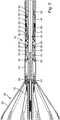
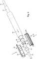
1 eine perspektivische Ansicht auf einen Pumpenkopf einer erfindungsgemäßen Katheterpumpe mit teilaufgeschnittener proximalen Lagerstelle;2 einen Längsschnitt durch die in1 gezeigte proximale Lagerstelle und3 die in2 gezeigte Lagerstelle vor deren Montage.
1 a perspective view of a pump head of a catheter pump according to the invention with partially cut proximal bearing point;2 a longitudinal section through the in1 shown proximal bearing and3 in the2 Shown bearing before assembly.
Die in der
Wie aus dem Schnitt gemäß
Die Drehlagerstelle
In der Drehlagerstelle
In der Krafteinleitstelle
Die Lageraufnahme
Durch die beschriebene Anordnung kann durch axiales Bewegen des Außenkatheters
In der in der
Wie aus
Die Buchse
Wie aus
Die Buchse
Durch den beschriebenen Aufbau der proximalen Lagerstelle
ZITATE ENTHALTEN IN DER BESCHREIBUNG QUOTES INCLUDE IN THE DESCRIPTION
Diese Liste der vom Anmelder aufgeführten Dokumente wurde automatisiert erzeugt und ist ausschließlich zur besseren Information des Lesers aufgenommen. Die Liste ist nicht Bestandteil der deutschen Patent- bzw. Gebrauchsmusteranmeldung. Das DPMA übernimmt keinerlei Haftung für etwaige Fehler oder Auslassungen.This list of the documents listed by the applicant has been generated automatically and is included solely for the better information of the reader. The list is not part of the German patent or utility model application. The DPMA assumes no liability for any errors or omissions.
Zitierte PatentliteraturCited patent literature
- EP 2308422 B1 [0002]EP 2308422 B1 [0002]
- EP 768900 B1 [0002]EP 768900 B1 [0002]
Claims (9)
Translated fromGermanPriority Applications (9)
| Application Number | Priority Date | Filing Date | Title |
|---|---|---|---|
| DE102017102828.5ADE102017102828A1 (en) | 2017-02-13 | 2017-02-13 | Catheter pump with a pump head for insertion into the arterial vasculature |
| CN201880011290.6ACN110290818B (en) | 2017-02-13 | 2018-02-08 | Catheter pump with pump head for introducing into arterial vascular system |
| JP2019540051AJP6825114B2 (en) | 2017-02-13 | 2018-02-08 | Catheter pump with pump head for introduction into arterial vessels |
| BR112019016700-5ABR112019016700B1 (en) | 2017-02-13 | 2018-02-08 | CATHETER PUMP PROVIDED WITH A PUMP HEAD FOR INSERTION INTO THE ARTERIAL VASCULARIZATION |
| EP18704228.8AEP3393543B1 (en) | 2017-02-13 | 2018-02-08 | Catheter pump with pump head for introduction in arterial vessel system |
| RU2019128509ARU2723535C1 (en) | 2017-02-13 | 2018-02-08 | Catheter pump with pump head for insertion into arterial blood system |
| US16/484,811US11697016B2 (en) | 2017-02-13 | 2018-02-08 | Catheter pump having a pump head for introducing into the arterial vasculature |
| PCT/EP2018/053125WO2018146173A1 (en) | 2017-02-13 | 2018-02-08 | Catheter pump having a pump head for introducing into the arterial vasculature |
| ES18704228TES2755810T3 (en) | 2017-02-13 | 2018-02-08 | Catheter pump with a pump head to introduce into the arterial vascular system |
Applications Claiming Priority (1)
| Application Number | Priority Date | Filing Date | Title |
|---|---|---|---|
| DE102017102828.5ADE102017102828A1 (en) | 2017-02-13 | 2017-02-13 | Catheter pump with a pump head for insertion into the arterial vasculature |
Publications (1)
| Publication Number | Publication Date |
|---|---|
| DE102017102828A1true DE102017102828A1 (en) | 2018-08-16 |
Family
ID=61189460
Family Applications (1)
| Application Number | Title | Priority Date | Filing Date |
|---|---|---|---|
| DE102017102828.5ACeasedDE102017102828A1 (en) | 2017-02-13 | 2017-02-13 | Catheter pump with a pump head for insertion into the arterial vasculature |
Country Status (8)
| Country | Link |
|---|---|
| US (1) | US11697016B2 (en) |
| EP (1) | EP3393543B1 (en) |
| JP (1) | JP6825114B2 (en) |
| CN (1) | CN110290818B (en) |
| DE (1) | DE102017102828A1 (en) |
| ES (1) | ES2755810T3 (en) |
| RU (1) | RU2723535C1 (en) |
| WO (1) | WO2018146173A1 (en) |
Families Citing this family (32)
| Publication number | Priority date | Publication date | Assignee | Title |
|---|---|---|---|---|
| CA3066361A1 (en) | 2017-06-07 | 2018-12-13 | Shifamed Holdings, Llc | Intravascular fluid movement devices, systems, and methods of use |
| WO2019094963A1 (en) | 2017-11-13 | 2019-05-16 | Shifamed Holdings, Llc | Intravascular fluid movement devices, systems, and methods of use |
| DE102018201030B4 (en) | 2018-01-24 | 2025-10-16 | Kardion Gmbh | Magnetic dome element with magnetic bearing function |
| CN112004563B (en) | 2018-02-01 | 2024-08-06 | 施菲姆德控股有限责任公司 | Intravascular blood pump and methods of use and manufacture |
| US11602627B2 (en) | 2018-03-20 | 2023-03-14 | Second Heart Assist, Inc. | Circulatory assist pump |
| US11690997B2 (en) | 2018-04-06 | 2023-07-04 | Puzzle Medical Devices Inc. | Mammalian body conduit intralumenal device and lumen wall anchor assembly, components thereof and methods of implantation and explanation thereof |
| DE102018207575A1 (en) | 2018-05-16 | 2019-11-21 | Kardion Gmbh | Magnetic face turning coupling for the transmission of torques |
| DE102018207611A1 (en) | 2018-05-16 | 2019-11-21 | Kardion Gmbh | Rotor bearing system |
| DE102018208550A1 (en) | 2018-05-30 | 2019-12-05 | Kardion Gmbh | A lead device for directing blood flow to a cardiac assist system, cardiac assist system, and method of making a lead device |
| DE102018208541A1 (en) | 2018-05-30 | 2019-12-05 | Kardion Gmbh | Axial pump for a cardiac assist system and method of making an axial pump for a cardiac assist system |
| DE102018208539A1 (en) | 2018-05-30 | 2019-12-05 | Kardion Gmbh | A motor housing module for sealing an engine compartment of a motor of a cardiac assist system and cardiac assistance system and method for mounting a cardiac assist system |
| DE102018208555A1 (en)* | 2018-05-30 | 2019-12-05 | Kardion Gmbh | Apparatus for anchoring a cardiac assist system in a blood vessel, method of operation, and method of making a device and cardiac assist system |
| DE102018208538A1 (en) | 2018-05-30 | 2019-12-05 | Kardion Gmbh | Intravascular blood pump and process for the production of electrical conductors |
| DE102018210058A1 (en) | 2018-06-21 | 2019-12-24 | Kardion Gmbh | Stator blade device for guiding the flow of a fluid flowing out of an outlet opening of a heart support system, heart support system with stator blade device, method for operating a stator blade device and manufacturing method |
| DE102018210076A1 (en) | 2018-06-21 | 2019-12-24 | Kardion Gmbh | Method and device for detecting a state of wear of a cardiac support system, method and device for operating a cardiac support system and cardiac support system |
| DE102018211327A1 (en) | 2018-07-10 | 2020-01-16 | Kardion Gmbh | Impeller for an implantable vascular support system |
| DE102018212153A1 (en) | 2018-07-20 | 2020-01-23 | Kardion Gmbh | Inlet line for a pump unit of a cardiac support system, cardiac support system and method for producing an inlet line for a pump unit of a cardiac support system |
| US12161857B2 (en) | 2018-07-31 | 2024-12-10 | Shifamed Holdings, Llc | Intravascular blood pumps and methods of use |
| CN112654389A (en) | 2018-08-07 | 2021-04-13 | 开迪恩有限公司 | Bearing device for a cardiac support system and method for flushing an intermediate space in a bearing device for a cardiac support system |
| WO2020073047A1 (en) | 2018-10-05 | 2020-04-09 | Shifamed Holdings, Llc | Intravascular blood pumps and methods of use |
| JP7729779B2 (en) | 2019-03-26 | 2025-08-26 | パズル メディカル デバイシズ インコーポレイテッド | Modular mammalian body implantable fluid flow affecting device and related methods |
| WO2021011473A1 (en) | 2019-07-12 | 2021-01-21 | Shifamed Holdings, Llc | Intravascular blood pumps and methods of manufacture and use |
| US11654275B2 (en) | 2019-07-22 | 2023-05-23 | Shifamed Holdings, Llc | Intravascular blood pumps with struts and methods of use and manufacture |
| WO2021062265A1 (en) | 2019-09-25 | 2021-04-01 | Shifamed Holdings, Llc | Intravascular blood pump systems and methods of use and control thereof |
| EP4501393A3 (en) | 2019-09-25 | 2025-04-09 | Shifamed Holdings, LLC | Catheter blood pumps and collapsible pump housings |
| US12121713B2 (en) | 2019-09-25 | 2024-10-22 | Shifamed Holdings, Llc | Catheter blood pumps and collapsible blood conduits |
| US12383723B2 (en) | 2019-10-05 | 2025-08-12 | Puzzle Medical Devices Inc. | Mammalian body implantable fluid flow influencing device |
| EP4072650A4 (en) | 2019-12-11 | 2024-01-10 | Shifamed Holdings, LLC | Descending aorta and vena cava blood pumps |
| EP3858397A1 (en)* | 2020-01-31 | 2021-08-04 | Abiomed Europe GmbH | Intravascular blood pump |
| DE102020102474A1 (en) | 2020-01-31 | 2021-08-05 | Kardion Gmbh | Pump for conveying a fluid and method for manufacturing a pump |
| CN112245794A (en)* | 2020-11-17 | 2021-01-22 | 苏州心岭迈德医疗科技有限公司 | Auxiliary blood pumping device and ventricular auxiliary blood pumping system |
| WO2024092349A1 (en) | 2022-11-01 | 2024-05-10 | Puzzle Medical Devices Inc. | Implantable medical devices and related methods thereof |
Citations (1)
| Publication number | Priority date | Publication date | Assignee | Title |
|---|---|---|---|---|
| DE202009018145U1 (en) | 2008-06-23 | 2011-05-05 | Cardiobridge Gmbh | Catheter pump for the support of the circulation |
Family Cites Families (11)
| Publication number | Priority date | Publication date | Assignee | Title |
|---|---|---|---|---|
| SE501215C2 (en)* | 1992-09-02 | 1994-12-12 | Oeyvind Reitan | catheter Pump |
| DE29804046U1 (en)* | 1998-03-07 | 1998-04-30 | Günther, Rolf W., Prof. Dr.med., 52074 Aachen | Percutaneously implantable, self-expanding axial pump for temporary heart support |
| AU2003236497A1 (en)* | 2002-06-11 | 2003-12-22 | Walid Aboul-Hosn | Expandable blood pump and related methods |
| EP2151257B1 (en)* | 2004-08-13 | 2013-04-17 | Delgado, Reynolds M., III | Apparatus for long-term assisting a left ventricle to pump blood |
| DE102006036948A1 (en)* | 2006-08-06 | 2008-02-07 | Akdis, Mustafa, Dipl.-Ing. | blood pump |
| ATE480274T1 (en)* | 2007-10-08 | 2010-09-15 | Ais Gmbh Aachen Innovative Sol | CATHETER DEVICE |
| US8489190B2 (en)* | 2007-10-08 | 2013-07-16 | Ais Gmbh Aachen Innovative Solutions | Catheter device |
| US8617239B2 (en)* | 2009-05-18 | 2013-12-31 | Cardiobridge Gmbh | Catheter pump |
| WO2012094535A2 (en)* | 2011-01-06 | 2012-07-12 | Thoratec Corporation | Percutaneous heart pump |
| EP4233702A3 (en)* | 2013-03-13 | 2023-12-20 | Magenta Medical Ltd. | Manufacture of an impeller |
| EP2868331B1 (en)* | 2013-11-01 | 2016-07-13 | ECP Entwicklungsgesellschaft mbH | Pump, in particular blood pump |
- 2017
- 2017-02-13DEDE102017102828.5Apatent/DE102017102828A1/ennot_activeCeased
- 2018
- 2018-02-08RURU2019128509Apatent/RU2723535C1/enactive
- 2018-02-08ESES18704228Tpatent/ES2755810T3/enactiveActive
- 2018-02-08CNCN201880011290.6Apatent/CN110290818B/enactiveActive
- 2018-02-08EPEP18704228.8Apatent/EP3393543B1/enactiveActive
- 2018-02-08USUS16/484,811patent/US11697016B2/enactiveActive
- 2018-02-08JPJP2019540051Apatent/JP6825114B2/enactiveActive
- 2018-02-08WOPCT/EP2018/053125patent/WO2018146173A1/ennot_activeCeased
Patent Citations (1)
| Publication number | Priority date | Publication date | Assignee | Title |
|---|---|---|---|---|
| DE202009018145U1 (en) | 2008-06-23 | 2011-05-05 | Cardiobridge Gmbh | Catheter pump for the support of the circulation |
Also Published As
| Publication number | Publication date |
|---|---|
| US20200023109A1 (en) | 2020-01-23 |
| BR112019016700A2 (en) | 2020-04-07 |
| US11697016B2 (en) | 2023-07-11 |
| WO2018146173A1 (en) | 2018-08-16 |
| CN110290818B (en) | 2021-11-23 |
| ES2755810T3 (en) | 2020-04-23 |
| EP3393543A1 (en) | 2018-10-31 |
| JP2020507368A (en) | 2020-03-12 |
| JP6825114B2 (en) | 2021-02-03 |
| RU2723535C1 (en) | 2020-06-15 |
| EP3393543B1 (en) | 2019-08-14 |
| CN110290818A (en) | 2019-09-27 |
Similar Documents
| Publication | Publication Date | Title |
|---|---|---|
| EP3393543B1 (en) | Catheter pump with pump head for introduction in arterial vessel system | |
| EP3402545B1 (en) | Catheter pump with pump head for introduction in the arterial vessel system | |
| EP3579904B1 (en) | Catheter pump comprising drive unit and catheter | |
| EP3856276B1 (en) | Sealed micropump | |
| EP3359215B1 (en) | Pump, in particular blood pump | |
| DE112010003744B4 (en) | Rotor for an axial pump for conveying a fluid | |
| EP3579894B1 (en) | Catheter pump with drive unit and catheter | |
| EP3000493B2 (en) | Catheter device | |
| DE112021000797T5 (en) | INTRAVASCULAR BLOOD PUMP | |
| WO2020011797A1 (en) | Impeller housing for an implantable, vascular support system | |
| EP2366412B1 (en) | Catheter device | |
| DE69630815T2 (en) | IMPLANTABLE, ELECTRIC AXIAL BLOOD PUMP WITH BLOOD-COOLED BEARINGS | |
| DE112021000561T5 (en) | Intravascular blood pump with outflow tube | |
| WO2019229214A1 (en) | Pump housing device, method for producing a pump housing device, and pump having a pump housing device | |
| EP2194278A1 (en) | Fluid pump with a rotor | |
| EP1738783A1 (en) | Axial flow pump with helical blade | |
| DE112011102347T5 (en) | Blood pump for invasive use within a patient's body | |
| DE112011102353T5 (en) | Radially compressible and expandable rotor for a pump with an airfoil | |
| EP2338540A1 (en) | Delivery blade for a compressible rotor | |
| DE112010003745T5 (en) | Fluid pump with at least one airfoil and a support means | |
| EP2525099A1 (en) | Rotary pump with two bearing elements and a flow channel |
Legal Events
| Date | Code | Title | Description |
|---|---|---|---|
| R012 | Request for examination validly filed | ||
| R079 | Amendment of ipc main class | Free format text:PREVIOUS MAIN CLASS: A61M0001120000 Ipc:A61M0060122000 | |
| R002 | Refusal decision in examination/registration proceedings | ||
| R003 | Refusal decision now final |