DE102017102824A1 - Catheter pump with drive unit and catheter - Google Patents
Catheter pump with drive unit and catheterDownload PDFInfo
- Publication number
- DE102017102824A1 DE102017102824A1DE102017102824.2ADE102017102824ADE102017102824A1DE 102017102824 A1DE102017102824 A1DE 102017102824A1DE 102017102824 ADE102017102824 ADE 102017102824ADE 102017102824 A1DE102017102824 A1DE 102017102824A1
- Authority
- DE
- Germany
- Prior art keywords
- catheter
- base
- pump
- sleeve
- proximal
- Prior art date
- Legal status (The legal status is an assumption and is not a legal conclusion. Google has not performed a legal analysis and makes no representation as to the accuracy of the status listed.)
- Withdrawn
Links
- 230000037431insertionEffects0.000claimsabstractdescription5
- 238000003780insertionMethods0.000claimsabstractdescription5
- 239000007788liquidSubstances0.000claimsdescription15
- 238000011010flushing procedureMethods0.000claimsdescription10
- 239000012530fluidSubstances0.000claimsdescription9
- 230000008878couplingEffects0.000claimsdescription7
- 238000010168coupling processMethods0.000claimsdescription7
- 238000005859coupling reactionMethods0.000claimsdescription7
- 210000005249arterial vasculatureAnatomy0.000claimsdescription2
- 230000005540biological transmissionEffects0.000claims1
- 210000000709aortaAnatomy0.000abstractdescription4
- 241000792859EnemaSpecies0.000description3
- 239000007920enemaSubstances0.000description3
- 229940095399enemaDrugs0.000description3
- 238000005461lubricationMethods0.000description2
- 238000007789sealingMethods0.000description2
- BUHVIAUBTBOHAG-FOYDDCNASA-N(2r,3r,4s,5r)-2-[6-[[2-(3,5-dimethoxyphenyl)-2-(2-methylphenyl)ethyl]amino]purin-9-yl]-5-(hydroxymethyl)oxolane-3,4-diolChemical compoundCOC1=CC(OC)=CC(C(CNC=2C=3N=CN(C=3N=CN=2)[C@H]2[C@@H]([C@H](O)[C@@H](CO)O2)O)C=2C(=CC=CC=2)C)=C1BUHVIAUBTBOHAG-FOYDDCNASA-N0.000description1
- 239000008280bloodSubstances0.000description1
- 210000004369bloodAnatomy0.000description1
- 238000011109contaminationMethods0.000description1
- 238000001816coolingMethods0.000description1
- 238000007599dischargingMethods0.000description1
- 238000006073displacement reactionMethods0.000description1
- 230000002996emotional effectEffects0.000description1
- 230000001050lubricating effectEffects0.000description1
- 230000002792vascularEffects0.000description1
Images

Classifications
- A—HUMAN NECESSITIES
- A61—MEDICAL OR VETERINARY SCIENCE; HYGIENE
- A61M—DEVICES FOR INTRODUCING MEDIA INTO, OR ONTO, THE BODY; DEVICES FOR TRANSDUCING BODY MEDIA OR FOR TAKING MEDIA FROM THE BODY; DEVICES FOR PRODUCING OR ENDING SLEEP OR STUPOR
- A61M25/00—Catheters; Hollow probes
- A61M25/0097—Catheters; Hollow probes characterised by the hub
- A—HUMAN NECESSITIES
- A61—MEDICAL OR VETERINARY SCIENCE; HYGIENE
- A61M—DEVICES FOR INTRODUCING MEDIA INTO, OR ONTO, THE BODY; DEVICES FOR TRANSDUCING BODY MEDIA OR FOR TAKING MEDIA FROM THE BODY; DEVICES FOR PRODUCING OR ENDING SLEEP OR STUPOR
- A61M25/00—Catheters; Hollow probes
- A61M25/0021—Catheters; Hollow probes characterised by the form of the tubing
- A—HUMAN NECESSITIES
- A61—MEDICAL OR VETERINARY SCIENCE; HYGIENE
- A61M—DEVICES FOR INTRODUCING MEDIA INTO, OR ONTO, THE BODY; DEVICES FOR TRANSDUCING BODY MEDIA OR FOR TAKING MEDIA FROM THE BODY; DEVICES FOR PRODUCING OR ENDING SLEEP OR STUPOR
- A61M25/00—Catheters; Hollow probes
- A61M25/0067—Catheters; Hollow probes characterised by the distal end, e.g. tips
- A61M25/0074—Dynamic characteristics of the catheter tip, e.g. openable, closable, expandable or deformable
- A—HUMAN NECESSITIES
- A61—MEDICAL OR VETERINARY SCIENCE; HYGIENE
- A61M—DEVICES FOR INTRODUCING MEDIA INTO, OR ONTO, THE BODY; DEVICES FOR TRANSDUCING BODY MEDIA OR FOR TAKING MEDIA FROM THE BODY; DEVICES FOR PRODUCING OR ENDING SLEEP OR STUPOR
- A61M25/00—Catheters; Hollow probes
- A61M25/01—Introducing, guiding, advancing, emplacing or holding catheters
- A61M25/02—Holding devices, e.g. on the body
- A61M25/04—Holding devices, e.g. on the body in the body, e.g. expansible
- A—HUMAN NECESSITIES
- A61—MEDICAL OR VETERINARY SCIENCE; HYGIENE
- A61M—DEVICES FOR INTRODUCING MEDIA INTO, OR ONTO, THE BODY; DEVICES FOR TRANSDUCING BODY MEDIA OR FOR TAKING MEDIA FROM THE BODY; DEVICES FOR PRODUCING OR ENDING SLEEP OR STUPOR
- A61M60/00—Blood pumps; Devices for mechanical circulatory actuation; Balloon pumps for circulatory assistance
- A61M60/10—Location thereof with respect to the patient's body
- A61M60/122—Implantable pumps or pumping devices, i.e. the blood being pumped inside the patient's body
- A61M60/126—Implantable pumps or pumping devices, i.e. the blood being pumped inside the patient's body implantable via, into, inside, in line, branching on, or around a blood vessel
- A61M60/13—Implantable pumps or pumping devices, i.e. the blood being pumped inside the patient's body implantable via, into, inside, in line, branching on, or around a blood vessel by means of a catheter allowing explantation, e.g. catheter pumps temporarily introduced via the vascular system
- A—HUMAN NECESSITIES
- A61—MEDICAL OR VETERINARY SCIENCE; HYGIENE
- A61M—DEVICES FOR INTRODUCING MEDIA INTO, OR ONTO, THE BODY; DEVICES FOR TRANSDUCING BODY MEDIA OR FOR TAKING MEDIA FROM THE BODY; DEVICES FOR PRODUCING OR ENDING SLEEP OR STUPOR
- A61M60/00—Blood pumps; Devices for mechanical circulatory actuation; Balloon pumps for circulatory assistance
- A61M60/40—Details relating to driving
- A61M60/403—Details relating to driving for non-positive displacement blood pumps
- A61M60/408—Details relating to driving for non-positive displacement blood pumps the force acting on the blood contacting member being mechanical, e.g. transmitted by a shaft or cable
- A61M60/411—Details relating to driving for non-positive displacement blood pumps the force acting on the blood contacting member being mechanical, e.g. transmitted by a shaft or cable generated by an electromotor
- A61M60/414—Details relating to driving for non-positive displacement blood pumps the force acting on the blood contacting member being mechanical, e.g. transmitted by a shaft or cable generated by an electromotor transmitted by a rotating cable, e.g. for blood pumps mounted on a catheter
- A—HUMAN NECESSITIES
- A61—MEDICAL OR VETERINARY SCIENCE; HYGIENE
- A61M—DEVICES FOR INTRODUCING MEDIA INTO, OR ONTO, THE BODY; DEVICES FOR TRANSDUCING BODY MEDIA OR FOR TAKING MEDIA FROM THE BODY; DEVICES FOR PRODUCING OR ENDING SLEEP OR STUPOR
- A61M60/00—Blood pumps; Devices for mechanical circulatory actuation; Balloon pumps for circulatory assistance
- A61M60/40—Details relating to driving
- A61M60/403—Details relating to driving for non-positive displacement blood pumps
- A61M60/408—Details relating to driving for non-positive displacement blood pumps the force acting on the blood contacting member being mechanical, e.g. transmitted by a shaft or cable
- A61M60/411—Details relating to driving for non-positive displacement blood pumps the force acting on the blood contacting member being mechanical, e.g. transmitted by a shaft or cable generated by an electromotor
- A61M60/416—Details relating to driving for non-positive displacement blood pumps the force acting on the blood contacting member being mechanical, e.g. transmitted by a shaft or cable generated by an electromotor transmitted directly by the motor rotor drive shaft
- A—HUMAN NECESSITIES
- A61—MEDICAL OR VETERINARY SCIENCE; HYGIENE
- A61M—DEVICES FOR INTRODUCING MEDIA INTO, OR ONTO, THE BODY; DEVICES FOR TRANSDUCING BODY MEDIA OR FOR TAKING MEDIA FROM THE BODY; DEVICES FOR PRODUCING OR ENDING SLEEP OR STUPOR
- A61M60/00—Blood pumps; Devices for mechanical circulatory actuation; Balloon pumps for circulatory assistance
- A61M60/40—Details relating to driving
- A61M60/403—Details relating to driving for non-positive displacement blood pumps
- A61M60/419—Details relating to driving for non-positive displacement blood pumps the force acting on the blood contacting member being permanent magnetic, e.g. from a rotating magnetic coupling between driving and driven magnets
- A—HUMAN NECESSITIES
- A61—MEDICAL OR VETERINARY SCIENCE; HYGIENE
- A61M—DEVICES FOR INTRODUCING MEDIA INTO, OR ONTO, THE BODY; DEVICES FOR TRANSDUCING BODY MEDIA OR FOR TAKING MEDIA FROM THE BODY; DEVICES FOR PRODUCING OR ENDING SLEEP OR STUPOR
- A61M60/00—Blood pumps; Devices for mechanical circulatory actuation; Balloon pumps for circulatory assistance
- A61M60/40—Details relating to driving
- A61M60/403—Details relating to driving for non-positive displacement blood pumps
- A61M60/422—Details relating to driving for non-positive displacement blood pumps the force acting on the blood contacting member being electromagnetic, e.g. using canned motor pumps
- A—HUMAN NECESSITIES
- A61—MEDICAL OR VETERINARY SCIENCE; HYGIENE
- A61M—DEVICES FOR INTRODUCING MEDIA INTO, OR ONTO, THE BODY; DEVICES FOR TRANSDUCING BODY MEDIA OR FOR TAKING MEDIA FROM THE BODY; DEVICES FOR PRODUCING OR ENDING SLEEP OR STUPOR
- A61M60/00—Blood pumps; Devices for mechanical circulatory actuation; Balloon pumps for circulatory assistance
- A61M60/80—Constructional details other than related to driving
- A61M60/802—Constructional details other than related to driving of non-positive displacement blood pumps
- A61M60/804—Impellers
- A61M60/806—Vanes or blades
- A61M60/808—Vanes or blades specially adapted for deformable impellers, e.g. expandable impellers
- A—HUMAN NECESSITIES
- A61—MEDICAL OR VETERINARY SCIENCE; HYGIENE
- A61M—DEVICES FOR INTRODUCING MEDIA INTO, OR ONTO, THE BODY; DEVICES FOR TRANSDUCING BODY MEDIA OR FOR TAKING MEDIA FROM THE BODY; DEVICES FOR PRODUCING OR ENDING SLEEP OR STUPOR
- A61M60/00—Blood pumps; Devices for mechanical circulatory actuation; Balloon pumps for circulatory assistance
- A61M60/80—Constructional details other than related to driving
- A61M60/802—Constructional details other than related to driving of non-positive displacement blood pumps
- A61M60/818—Bearings
- A61M60/825—Contact bearings, e.g. ball-and-cup or pivot bearings
- A—HUMAN NECESSITIES
- A61—MEDICAL OR VETERINARY SCIENCE; HYGIENE
- A61M—DEVICES FOR INTRODUCING MEDIA INTO, OR ONTO, THE BODY; DEVICES FOR TRANSDUCING BODY MEDIA OR FOR TAKING MEDIA FROM THE BODY; DEVICES FOR PRODUCING OR ENDING SLEEP OR STUPOR
- A61M60/00—Blood pumps; Devices for mechanical circulatory actuation; Balloon pumps for circulatory assistance
- A61M60/80—Constructional details other than related to driving
- A61M60/802—Constructional details other than related to driving of non-positive displacement blood pumps
- A61M60/827—Sealings between moving parts
- A61M60/829—Sealings between moving parts having a purge fluid supply
- A—HUMAN NECESSITIES
- A61—MEDICAL OR VETERINARY SCIENCE; HYGIENE
- A61M—DEVICES FOR INTRODUCING MEDIA INTO, OR ONTO, THE BODY; DEVICES FOR TRANSDUCING BODY MEDIA OR FOR TAKING MEDIA FROM THE BODY; DEVICES FOR PRODUCING OR ENDING SLEEP OR STUPOR
- A61M60/00—Blood pumps; Devices for mechanical circulatory actuation; Balloon pumps for circulatory assistance
- A61M60/80—Constructional details other than related to driving
- A61M60/855—Constructional details other than related to driving of implantable pumps or pumping devices
- A61M60/857—Implantable blood tubes
- A—HUMAN NECESSITIES
- A61—MEDICAL OR VETERINARY SCIENCE; HYGIENE
- A61M—DEVICES FOR INTRODUCING MEDIA INTO, OR ONTO, THE BODY; DEVICES FOR TRANSDUCING BODY MEDIA OR FOR TAKING MEDIA FROM THE BODY; DEVICES FOR PRODUCING OR ENDING SLEEP OR STUPOR
- A61M25/00—Catheters; Hollow probes
- A61M2025/0004—Catheters; Hollow probes having two or more concentrically arranged tubes for forming a concentric catheter system
Landscapes
- Health & Medical Sciences (AREA)
- Heart & Thoracic Surgery (AREA)
- Engineering & Computer Science (AREA)
- Life Sciences & Earth Sciences (AREA)
- Hematology (AREA)
- Public Health (AREA)
- Biomedical Technology (AREA)
- Anesthesiology (AREA)
- Veterinary Medicine (AREA)
- Animal Behavior & Ethology (AREA)
- General Health & Medical Sciences (AREA)
- Mechanical Engineering (AREA)
- Cardiology (AREA)
- Biophysics (AREA)
- Pulmonology (AREA)
- Vascular Medicine (AREA)
- External Artificial Organs (AREA)
- Media Introduction/Drainage Providing Device (AREA)
- Transplantation (AREA)
Abstract
Translated fromGermanDescription
Translated fromGermanDie Erfindung betrifft eine Katheterpumpe mit einem Katheter, mit einem am distalen Ende des Katheters vorgesehenen Pumpenkopf zum Einführen in das arterielle Gefäßsystem, insbesondere in die Aorta oder das Herz, wobei der Katheter einen Außenkatheter und einen im Außenkatheter angeordneten Innenkatheter aufweist, mit einer im Innenkatheter verdrehbar angeordneten Rotorwelle zum Antreiben eines am Pumpenkopf vorgesehenen, expandierbaren Förderelements, mit einem am proximalen Ende des Katheters vorgesehenen Betätigungsabschnitt, über den die Rotorwelle antreibbar ist, mit einem das Förderelement umgebenden Käfig, wobei der Käfig eine distale und eine proximale Hülse sowie zwischen den Hülsen verlaufende Filamente aufweist, wobei die proximale Hülse zum Expandieren des Käfigs in axialer Richtung hin zur distalen Hülse bewegt werden kann. Dabei expandieren die zwischen den Hülsen liegenden Bereiche der Filamente nach radial außen, um einen das expandierende Förderelement umgebenden Raum zu bilden.The invention relates to a catheter pump with a catheter, with a provided at the distal end of the catheter pump head for insertion into the arterial vascular system, in particular in the aorta or the heart, the catheter having an outer catheter and an outer catheter disposed in the inner catheter, with an inner catheter rotatably arranged rotor shaft for driving a provided on the pump head, expandable conveying element, with an actuating portion provided at the proximal end of the catheter, via which the rotor shaft is driven, with a cage surrounding the conveying element, wherein the cage has a distal and a proximal sleeve and between the sleeves extending filaments, wherein the proximal sleeve can be moved to expand the cage in the axial direction towards the distal sleeve. The areas of the filaments lying between the sleeves expand radially outwards in order to form a space surrounding the expanding conveying element.
Derartige Katheterpumpen sind beispielsweise aus der
Katheterpumpen werden als temporäres Kreislaufunterstützungssystem in das arterielle Gefäßsystem wie zum Beispiel die Aorta von Patienten eingesetzt, insbesondere dann, wenn das natürliche Herz nicht in der Lage ist, den Körper mit ausreichend Sauerstoff versetztem Blut zu versorgen. Das Förderelement und die Rotorwelle werden dabei mit vergleichsweise hohen Drehzahlen im Bereich von 7000 bis 15000 Umdrehungen betrieben. Der Pumpenkopf der Katheterpumpe kann mehrere Tage im Patienten verbleiben.Catheter pumps are used as a temporary circulatory support system in the arterial vasculature, such as the aorta of patients, especially when the natural heart is unable to provide the body with sufficient oxygenated blood. The conveying element and the rotor shaft are operated at relatively high speeds in the range of 7000 to 15000 revolutions. The pump head of the catheter pump may remain in the patient for several days.
Der vorliegenden Erfindung liegt die Aufgabe zugrunde, eine eingangs beschriebene Katheterpumpe bereitzustellen, mit der ein funktionssicheres Expandieren des Käfigs erfolgen kann.The present invention has for its object to provide a catheter pump described above, with a functionally reliable expansion of the cage can be done.
Diese Aufgabe wird mit einer Katheterpumpe mit den Merkmalen des Anspruchs 1 gelöst. Erfindungsgemäß ist folglich vorgesehen, dass der Betätigungsabschnitt ein in axialer Richtung mit dem Innenkatheter bewegungsgekoppeltes Grundteil und ein relativ zum Grundteil in axialer Richtung bewegbares, im oder am Grundteil geführt angeordnetes Betätigungsteil aufweist, wobei das proximale Ende des Außenkatheters mit dem Betätigungsteil und das distale Ende des Außenkatheters mit der proximalen Hülse in axialer Richtung derart bewegungsgekoppelt sind, dass beim Bewegen des Betätigungsteils weg vom Grundteil die proximale Hülse hin zur distalen Hülse bewegt wird.This object is achieved with a catheter pump having the features of claim 1. According to the invention, it is thus provided that the actuating section has a base part movably coupled in the axial direction with the inner catheter and an actuating part which is movable relative to the base part in the axial direction and guided in or on the base part, the proximal end of the outer catheter being connected to the actuating part and the distal end of the outer catheter Outside catheter with the proximal sleeve in the axial direction are coupled in such a way that when moving the actuating part away from the base, the proximal sleeve is moved towards the distal sleeve.
Dadurch, dass das Betätigungsteil in oder am Grundteil geführt angeordnet ist, kann eine sichere Relativbewegung zwischen Grundteil und Betätigungsteil gewährleistet werden. Zum anderen kann dadurch, dass das proximale Ende des Außenkatheters mit dem Betätigungsteil und das distale Ende des Außenkatheters mit der proximalen Hülse in axialer Richtung bewegungsgekoppelt sind, durch Betätigen des Betätigungsteils relativ zum Grundteil die proximale Hülse in distaler Richtung auf die distale Hülse zubewegt werden, so dass die Filamente des Käfigs nach radial außen expandieren, um einen Förderelement umgebenden Raum bereitzustellen. Das Grundteil ist dabei vorzugsweise proximal zum Betätigungsteil angeordnet, d.h. das Betätigungsteil befindet sich zwischen dem Grundteil und dem Pumpenkopf. Vorzugsweise wird beim Verschieben des Betätigungsteils hin zum Grundteil nicht nur der Käfig expandiert, sondern zeitgleich oder zeitlich kurz danach, das Förderelement aus seiner kollabierten bzw. eingeklappten Lage in die expandierte Lage betätigt.Characterized in that the actuating part is arranged guided in or on the base, a reliable relative movement between the base and operating part can be ensured. On the other hand, by the fact that the proximal end of the outer catheter with the actuating part and the distal end of the outer catheter are coupled with the proximal sleeve in the axial direction, by actuating the actuating part relative to the base part, the proximal sleeve can be moved in the distal direction towards the distal sleeve, such that the filaments of the cage expand radially outward to provide space surrounding a conveyor element. The base is preferably arranged proximal to the actuating part, i. the actuating part is located between the base and the pump head. Preferably, when moving the operating part towards the base not only the cage expands, but at the same time or shortly thereafter, the conveying element is actuated from its collapsed or folded position into the expanded position.
Zur ausreichenden Schmierung und Spülung der Lagerstellen des Förderelements ist es vorteilhaft, wenn das Betätigungsteil einen Einlauf für Spülflüssigkeit aufweist und wenn das Grundteil einen Auslauf für die von den Lagerstellen kommende Spülflüssigkeit aufweist. Insofern kann über das Betätigungsteil, bzw. über dessen Einlauf, Spülflüssigkeit in den Katheter gepumpt und zu den Lagerstellen geleitet werden. Über das Grundteil, bzw. dessen Auslauf, kann zumindest ein Teil der eingebrachten Spülflüssigkeit aus dem Katheter abgeführt werden.For adequate lubrication and flushing of the bearing points of the conveying element, it is advantageous if the actuating part has an inlet for flushing liquid and if the base part has an outlet for the flushing liquid coming from the bearing points. In this respect, flushing fluid can be pumped into the catheter and directed to the bearing points via the actuating part, or via its inlet. About the base, or its outlet, at least a portion of the introduced rinsing fluid can be removed from the catheter.
Dabei ist vorteilhaft, wenn das Betätigungsteil einen mit dem Einlauf verbundenen Einlaufraum aufweist, wobei der Innenkatheter sich durch den Einlaufraum erstreckt und der Einlaufraum mit einem zwischen dem Außenkatheter und dem Innenkatheter vorhandenen Einlauflumen verbunden ist, so dass durch den Einlauf kommende Spülflüssigkeit über den Einlaufraum und das Einlauflumen hin zu den Lagerstellen des Förderelements strömen kann. Dadurch kann erreicht werden, dass die Spülflüssigkeit nicht mit der im Innenkatheter rotierenden Welle in Kontakt kommt. Eine Verunreinigung der Spülflüssigkeit kann damit unterbunden werden. Der Innenkatheter mit darin im Betrieb rotierender Rotorwelle kann dennoch sicher durch den Einlaufraum hindurch zum Grundteil geführt werden.It is advantageous if the actuating part has an inlet space connected to the inlet, wherein the inner catheter extends through the inlet space and the inlet space is connected to an existing between the outer catheter and the inner catheter inlet lumen, so that coming through the inlet rinsing fluid through the inlet space and the inlet lumen can flow towards the bearing points of the conveying element. It can thereby be achieved that the rinsing fluid does not come into contact with the shaft rotating in the inner catheter. Contamination of the rinsing liquid can thus be prevented. The inner catheter with rotor shaft rotating therein during operation can nevertheless be guided safely through the inlet space to the base part.
Um dennoch eine Relativbewegung zwischen Betätigungsteil und Grundteil zu ermöglichen, ist vorteilhaft, wenn der Einlaufraum auf der proximalen Seite von einem im Einlaufraum axial verschiebbaren Kolbenabschnitt des Grundteils begrenzt ist. Dieser Kolbenabschnitt nimmt vorteilhafterweise das proximale Ende des Innenkatheters auf, durch den sich die Rotorwelle hin zum proximalen Ende des Grundteils erstreckt. Durch Vorsehen des Kolbenabschnitts kann erreicht werden, dass keine Spülflüssigkeit in proximaler Richtung aus dem Betätigungsteil strömen kann; dennoch kann das Betätigungsteil relativ zum Grundteil in axialer Richtung bewegt werden. Vorzugsweise weist der Kolbenabschnitt auf seiner radialen Außenseite einen umlaufenden Dichtring auf, der zum einen ein axiales Verschieben ermöglicht und zum anderen die Dichtheit des Einlaufraums sicherstellt. Der Einlaufraum ist dabei vorteilhafterweise ein möglichst kleines Volumen auf, um das Volumen des Einlaufraums bei einer Betätigung des Betätigungsabschnitts möglichst nur wenig zu verändern.To still allow a relative movement between the actuating part and the base part, it is advantageous if the inlet space on the Proximal side of a in the inlet space axially displaceable piston portion of the base is limited. This piston portion advantageously receives the proximal end of the inner catheter through which the rotor shaft extends toward the proximal end of the base. By providing the piston portion can be achieved that no flushing liquid can flow in the proximal direction of the actuating part; Nevertheless, the actuating part can be moved relative to the base in the axial direction. Preferably, the piston portion on its radial outer side on a circumferential sealing ring, on the one hand allows axial displacement and on the other ensures the tightness of the inlet space. The inlet space is advantageously the smallest possible volume in order to change as little as possible the volume of the inlet space upon actuation of the actuating portion.
Weiterhin ist vorteilhaft, wenn das Grundteil einen hülsenartig ausgebildeten Lagerabschnitt mit einem Aufnahmeraum aufweist, in dem Lagerstellen zur Drehlagerung des proximalen Endes der Rotorwelle vorgesehen sind. Das Grundteil sieht folglich an seinem distalen Abschnitt den Kolbenabschnitt und in proximaler Richtung daran anschließend den Lagerabschnitt vor. Die Rotorwelle erstreckt sich dabei in axialer Richtung durch den Aufnahmeraum. Die Rotorwelle als solches kann dabei einteilig oder mehrteilig ausgebildet sein. Um eine gute Lagerung des proximalen Endes der Rotorwelle zu erreichen, ist vorteilhaft, wenn diese im Aufnahmeraum starr ausgebildet ist. Im Katheter hingegen kann die Rotorwelle flexibel ausgebildet sein, so dass der Katheter samt Rotorwelle eine gewisse Flexibilität aufweist. Im Aufnahmeraum kann eine Lagerhülse vorgesehen sein, in der Lagerstellen in Form von Drehlagern, insbesondere in Form von Gleit-Wälzlagerringen, fixiert sind. Vorzugsweise sind zwei axial zueinander beabstandete Lagerstellen vorgesehen, um eine sichere Lagerung des proximalen Endes der Rotorwelle in insbesondere axialer und radialer Richtung zu gewährleisten. Zum Abführen der Spülflüssigkeit und zum Schmieren der in dem Innenkatheter rotierenden Rotorwelle ist vorteilhaft, wenn der Aufnahmeraum mit einem zwischen dem Innenkatheter und der Rotorwelle vorhandenen Auslauflumen verbunden ist, so dass durch das Auslauflumen kommende Spülflüssigkeit über den Aufnahmeraum hin zum Auslauf strömen kann.It is also advantageous if the base part has a sleeve-like bearing section with a receiving space, are provided in the bearing points for pivotally mounting the proximal end of the rotor shaft. The base thus provides at its distal portion the piston portion and in the proximal direction thereafter the bearing portion. The rotor shaft extends in the axial direction through the receiving space. The rotor shaft as such can be formed in one piece or in several parts. In order to achieve a good bearing of the proximal end of the rotor shaft, it is advantageous if this is rigid in the receiving space. In the catheter, however, the rotor shaft can be designed to be flexible, so that the catheter including the rotor shaft has a certain flexibility. In the receiving space, a bearing sleeve may be provided, are fixed in the bearing points in the form of pivot bearings, in particular in the form of sliding roller bearing rings. Preferably, two axially spaced bearings are provided to ensure safe storage of the proximal end of the rotor shaft in particular axial and radial directions. For discharging the rinsing liquid and for lubricating the rotor shaft rotating in the inner catheter, it is advantageous if the receiving space is connected to an outlet lumen present between the inner catheter and the rotor shaft, so that rinsing fluid coming through the outlet lumen can flow via the receiving space to the outlet.
Die Anordnung ist dabei derart, dass die Spülflüssigkeit, die aus dem Auslauflumen in den Aufnahmeraum einströmt, die Lagerstellen, mit denen das proximale Ende der Rotorwelle gelagert ist, zur Kühlung, Spülung und Schmierung durchströmt.The arrangement is such that the rinsing liquid, which flows from the outlet lumen into the receiving space, flows through the bearing points, with which the proximal end of the rotor shaft is mounted, for cooling, rinsing and lubrication.
Die Drehlager können dabei Ausnehmungen, beispielsweise in Form von sich in axialer Richtung erstreckenden Bohrungen aufweisen, durch die die Spülflüssigkeit geleitet werden kannThe pivot bearing can have recesses, for example in the form of extending in the axial direction holes through which the rinsing liquid can be passed
Das Grundteil sieht ferner vorteilhafterweise an seinem proximalen Ende einen mit dem Auslauf verbundenen Auslaufraum vor, wobei die vom Aufnahmeraum kommende Spülflüssigkeit, nachdem sie vorteilhafterweise die Lagerstellen durchströmt hat, durch den Auslaufraum in den Auslauf abfließt.The base also advantageously provides at its proximal end an outlet space connected to the outlet, wherein the flushing liquid coming from the receiving space, after it has advantageously flowed through the bearing points, flows through the outlet space into the outlet.
Das proximale, freie Ende der Rotorwelle sieht dabei vorzugsweise einen im Auslaufraum vorgesehenen Drehkoppelabschnitt vor. Der Drehkoppelabschnitt ist dabei über Magnetelemente mit einem Antrieb berührungslos drehkoppelbar.The proximal free end of the rotor shaft preferably provides a rotational coupling section provided in the outlet space. The rotary coupling section is non-contact rotatably coupled via magnetic elements with a drive.
Zur weiteren, sicheren gegenseitigen Führung von Betätigungsteil und Grundteil ist vorteilhaft, wenn das Betätigungsteil an seinem proximalen Ende eine zylinderförmige Schiebeaufnahme für einen kolbenartigen Schiebeabschnitt des Grundteils aufweist. Dadurch kann ein sicheres axiales Betätigen von Betätigungsteil und Grundteil erreicht werden, ohne dass ein Abknicken der Teile beim Aufeinanderzubewegen erfolgen kann.For further, secure mutual guidance of the actuating part and the base part is advantageous if the actuating part has at its proximal end a cylindrical sliding receptacle for a piston-like sliding portion of the base. As a result, a safe axial actuation of the actuating part and the base part can be achieved without the parts being able to be bent when moving toward one another.
Der Schiebeabschnitt wird dabei vorteilhafterweise abschnittsweise von der Außenseite des Lagerabschnitts gebildet.The sliding portion is advantageously formed in sections from the outside of the bearing section.
Weitere Vorteile und vorteilhafte Ausgestaltungen der Erfindung sind der nachfolgenden Beschreibung zu entnehmen, anhand derer ein Ausführungsbeispiel für die Erfindung näher beschrieben und erläutert ist.Further advantages and advantageous embodiments of the invention will become apparent from the following description, with reference to which an embodiment of the invention is described and explained in detail.
Es zeigen:
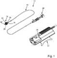
1 eine Katheterpumpe mit einer Antriebseinheit und einem Katheter;2 einen Längsschnitt durch den Betätigungsabschnitt der Katheterpumpe gemäß1 in nicht betätigter Einführlage des Pumpenkopfes; und3 den Betätigungsabschnitt gemäß1 in betätigter Betriebslage.
1 a catheter pump having a drive unit and a catheter;2 a longitudinal section through the operating portion of the catheter pump according to1 in non-actuated insertion position of the pump head; and3 the operating section according to1 in actuated operating position.
In der
An seinem proximalen Ende sieht der Katheter
In den Schnitten gemäß
Zum Ausklappen des Kä
Der Außenkatheter
Durch axiales Betätigen des Betätigungsteils
Wie aus
Im Betrieb strömt folglich Spülflüssigkeit, wie in
Wie aus den
Der Kolbenabschnitt
Das Grundteil
Der Aufnahmeraum
Am freien, proximalen Ende
Wie ebenfalls aus
Zur sicheren Führung des Betätigungsteils
Das Grundteil
ZITATE ENTHALTEN IN DER BESCHREIBUNG QUOTES INCLUDE IN THE DESCRIPTION
Diese Liste der vom Anmelder aufgeführten Dokumente wurde automatisiert erzeugt und ist ausschließlich zur besseren Information des Lesers aufgenommen. Die Liste ist nicht Bestandteil der deutschen Patent- bzw. Gebrauchsmusteranmeldung. Das DPMA übernimmt keinerlei Haftung für etwaige Fehler oder Auslassungen.This list of the documents listed by the applicant has been generated automatically and is included solely for the better information of the reader. The list is not part of the German patent or utility model application. The DPMA assumes no liability for any errors or omissions.
Zitierte PatentliteraturCited patent literature
- EP 2288392 B1 [0002]EP 2288392 B1 [0002]
Claims (12)
Translated fromGermanPriority Applications (9)
| Application Number | Priority Date | Filing Date | Title |
|---|---|---|---|
| DE102017102824.2ADE102017102824A1 (en) | 2017-02-13 | 2017-02-13 | Catheter pump with drive unit and catheter |
| RU2019128562ARU2733971C9 (en) | 2017-02-13 | 2018-02-08 | Catheter pump comprising drive unit, and catheter |
| JP2019543792AJP6927647B2 (en) | 2017-02-13 | 2018-02-08 | Catheter pump including drive unit and catheter |
| ES18704952TES2901020T3 (en) | 2017-02-13 | 2018-02-08 | Catheter pump with drive unit and catheter |
| BR112019016703-0ABR112019016703B1 (en) | 2017-02-13 | 2018-02-08 | CATHETER PUMP PROVIDED WITH DRIVE UNIT AND CATHETER |
| US16/484,808US11103690B2 (en) | 2017-02-13 | 2018-02-08 | Catheter pump comprising drive unit and catheter |
| PCT/EP2018/053131WO2018146177A1 (en) | 2017-02-13 | 2018-02-08 | Catheter pump comprising drive unit and catheter |
| EP18704952.3AEP3579904B1 (en) | 2017-02-13 | 2018-02-08 | Catheter pump comprising drive unit and catheter |
| CN201880011279.XACN110290825B (en) | 2017-02-13 | 2018-02-08 | Catheter pump with drive unit and catheter |
Applications Claiming Priority (1)
| Application Number | Priority Date | Filing Date | Title |
|---|---|---|---|
| DE102017102824.2ADE102017102824A1 (en) | 2017-02-13 | 2017-02-13 | Catheter pump with drive unit and catheter |
Publications (1)
| Publication Number | Publication Date |
|---|---|
| DE102017102824A1true DE102017102824A1 (en) | 2018-08-16 |
Family
ID=61198842
Family Applications (1)
| Application Number | Title | Priority Date | Filing Date |
|---|---|---|---|
| DE102017102824.2AWithdrawnDE102017102824A1 (en) | 2017-02-13 | 2017-02-13 | Catheter pump with drive unit and catheter |
Country Status (8)
| Country | Link |
|---|---|
| US (1) | US11103690B2 (en) |
| EP (1) | EP3579904B1 (en) |
| JP (1) | JP6927647B2 (en) |
| CN (1) | CN110290825B (en) |
| DE (1) | DE102017102824A1 (en) |
| ES (1) | ES2901020T3 (en) |
| RU (1) | RU2733971C9 (en) |
| WO (1) | WO2018146177A1 (en) |
Cited By (1)
| Publication number | Priority date | Publication date | Assignee | Title |
|---|---|---|---|---|
| CN118320295A (en)* | 2024-06-14 | 2024-07-12 | 安徽通灵仿生科技有限公司 | Flushing fluid sealing system of blood pump transmission device |
Families Citing this family (38)
| Publication number | Priority date | Publication date | Assignee | Title |
|---|---|---|---|---|
| CA3066361A1 (en) | 2017-06-07 | 2018-12-13 | Shifamed Holdings, Llc | Intravascular fluid movement devices, systems, and methods of use |
| WO2019094963A1 (en) | 2017-11-13 | 2019-05-16 | Shifamed Holdings, Llc | Intravascular fluid movement devices, systems, and methods of use |
| DE102018201030B4 (en) | 2018-01-24 | 2025-10-16 | Kardion Gmbh | Magnetic dome element with magnetic bearing function |
| CN112004563B (en) | 2018-02-01 | 2024-08-06 | 施菲姆德控股有限责任公司 | Intravascular blood pump and methods of use and manufacture |
| US11602627B2 (en) | 2018-03-20 | 2023-03-14 | Second Heart Assist, Inc. | Circulatory assist pump |
| US11690997B2 (en) | 2018-04-06 | 2023-07-04 | Puzzle Medical Devices Inc. | Mammalian body conduit intralumenal device and lumen wall anchor assembly, components thereof and methods of implantation and explanation thereof |
| DE102018207575A1 (en) | 2018-05-16 | 2019-11-21 | Kardion Gmbh | Magnetic face turning coupling for the transmission of torques |
| DE102018207611A1 (en) | 2018-05-16 | 2019-11-21 | Kardion Gmbh | Rotor bearing system |
| DE102018208538A1 (en) | 2018-05-30 | 2019-12-05 | Kardion Gmbh | Intravascular blood pump and process for the production of electrical conductors |
| DE102018208539A1 (en) | 2018-05-30 | 2019-12-05 | Kardion Gmbh | A motor housing module for sealing an engine compartment of a motor of a cardiac assist system and cardiac assistance system and method for mounting a cardiac assist system |
| DE102018208555A1 (en) | 2018-05-30 | 2019-12-05 | Kardion Gmbh | Apparatus for anchoring a cardiac assist system in a blood vessel, method of operation, and method of making a device and cardiac assist system |
| DE102018208541A1 (en) | 2018-05-30 | 2019-12-05 | Kardion Gmbh | Axial pump for a cardiac assist system and method of making an axial pump for a cardiac assist system |
| DE102018208550A1 (en) | 2018-05-30 | 2019-12-05 | Kardion Gmbh | A lead device for directing blood flow to a cardiac assist system, cardiac assist system, and method of making a lead device |
| DE102018210076A1 (en) | 2018-06-21 | 2019-12-24 | Kardion Gmbh | Method and device for detecting a state of wear of a cardiac support system, method and device for operating a cardiac support system and cardiac support system |
| DE102018210058A1 (en) | 2018-06-21 | 2019-12-24 | Kardion Gmbh | Stator blade device for guiding the flow of a fluid flowing out of an outlet opening of a heart support system, heart support system with stator blade device, method for operating a stator blade device and manufacturing method |
| DE102018211327A1 (en) | 2018-07-10 | 2020-01-16 | Kardion Gmbh | Impeller for an implantable vascular support system |
| DE102018212153A1 (en) | 2018-07-20 | 2020-01-23 | Kardion Gmbh | Inlet line for a pump unit of a cardiac support system, cardiac support system and method for producing an inlet line for a pump unit of a cardiac support system |
| US12161857B2 (en) | 2018-07-31 | 2024-12-10 | Shifamed Holdings, Llc | Intravascular blood pumps and methods of use |
| CN112654389A (en) | 2018-08-07 | 2021-04-13 | 开迪恩有限公司 | Bearing device for a cardiac support system and method for flushing an intermediate space in a bearing device for a cardiac support system |
| WO2020073047A1 (en) | 2018-10-05 | 2020-04-09 | Shifamed Holdings, Llc | Intravascular blood pumps and methods of use |
| JP7729779B2 (en) | 2019-03-26 | 2025-08-26 | パズル メディカル デバイシズ インコーポレイテッド | Modular mammalian body implantable fluid flow affecting device and related methods |
| WO2021011473A1 (en) | 2019-07-12 | 2021-01-21 | Shifamed Holdings, Llc | Intravascular blood pumps and methods of manufacture and use |
| US11654275B2 (en) | 2019-07-22 | 2023-05-23 | Shifamed Holdings, Llc | Intravascular blood pumps with struts and methods of use and manufacture |
| WO2021032282A1 (en)* | 2019-08-19 | 2021-02-25 | Reco2Lung Gmbh | Cannula comprising an expandable arrangement, corresponding cannula system and method for inserting at least one cannula into a subject |
| WO2021032283A1 (en)* | 2019-08-19 | 2021-02-25 | Reco2Lung Gmbh | Endovascular cannula for defining a border of a transport volume for an in-vivo fluid transport, cannula system and corresponding method |
| US20220323663A1 (en)* | 2019-08-19 | 2022-10-13 | Reco2Very Therapies Gmbh | Cannula Comprising an Expandable Arrangement, Corresponding Cannula System and Method for Inserting at Least One Cannula into a Subject |
| US12121713B2 (en) | 2019-09-25 | 2024-10-22 | Shifamed Holdings, Llc | Catheter blood pumps and collapsible blood conduits |
| WO2021062265A1 (en) | 2019-09-25 | 2021-04-01 | Shifamed Holdings, Llc | Intravascular blood pump systems and methods of use and control thereof |
| EP4501393A3 (en) | 2019-09-25 | 2025-04-09 | Shifamed Holdings, LLC | Catheter blood pumps and collapsible pump housings |
| US12383723B2 (en) | 2019-10-05 | 2025-08-12 | Puzzle Medical Devices Inc. | Mammalian body implantable fluid flow influencing device |
| EP4072650A4 (en) | 2019-12-11 | 2024-01-10 | Shifamed Holdings, LLC | Descending aorta and vena cava blood pumps |
| DE102020102474A1 (en) | 2020-01-31 | 2021-08-05 | Kardion Gmbh | Pump for conveying a fluid and method for manufacturing a pump |
| CN113289198B (en)* | 2021-04-16 | 2023-05-16 | 杭州未名信科科技有限公司 | Administration catheter and method for producing an administration catheter |
| CN113244525B (en)* | 2021-05-11 | 2023-07-04 | 丰凯利医疗器械(上海)有限公司 | Transmission support and shunt structure and blood pumping catheter |
| JP2025526924A (en)* | 2022-08-15 | 2025-08-15 | マグアシスト カンパニー,リミテッド | catheter pump |
| CN115364337B (en)* | 2022-09-28 | 2023-06-30 | 苏州心擎医疗技术有限公司 | Catheter device |
| WO2024092349A1 (en) | 2022-11-01 | 2024-05-10 | Puzzle Medical Devices Inc. | Implantable medical devices and related methods thereof |
| CN118320296B (en)* | 2024-06-14 | 2024-09-24 | 安徽通灵仿生科技有限公司 | Flushing system for blood pump transmission device |
Citations (1)
| Publication number | Priority date | Publication date | Assignee | Title |
|---|---|---|---|---|
| DE202009018145U1 (en) | 2008-06-23 | 2011-05-05 | Cardiobridge Gmbh | Catheter pump for the support of the circulation |
Family Cites Families (22)
| Publication number | Priority date | Publication date | Assignee | Title |
|---|---|---|---|---|
| SE501215C2 (en)* | 1992-09-02 | 1994-12-12 | Oeyvind Reitan | catheter Pump |
| US6652546B1 (en)* | 1996-07-26 | 2003-11-25 | Kensey Nash Corporation | System and method of use for revascularizing stenotic bypass grafts and other occluded blood vessels |
| US6905505B2 (en)* | 1996-07-26 | 2005-06-14 | Kensey Nash Corporation | System and method of use for agent delivery and revascularizing of grafts and vessels |
| US6331165B1 (en)* | 1996-11-25 | 2001-12-18 | Scimed Life Systems, Inc. | Biopsy instrument having irrigation and aspiration capabilities |
| AU7354400A (en)* | 1999-09-03 | 2001-04-10 | A-Med Systems, Inc. | Guidable intravascular blood pump and related methods |
| JP4731471B2 (en)* | 2003-04-16 | 2011-07-27 | ジェネシス・テクノロジーズ・エルエルシー | Medical devices and methods |
| US8475487B2 (en)* | 2005-04-07 | 2013-07-02 | Medrad, Inc. | Cross stream thrombectomy catheter with flexible and expandable cage |
| US9199020B2 (en)* | 2007-11-01 | 2015-12-01 | Abiomed, Inc. | Purge-free miniature rotary pump |
| WO2010009407A1 (en)* | 2008-07-17 | 2010-01-21 | Tyco Healthcare Group Lp | Spirally conformable infusion catheter |
| EP2246078A1 (en)* | 2009-04-29 | 2010-11-03 | ECP Entwicklungsgesellschaft mbH | Shaft assembly with a shaft which moves within a fluid-filled casing |
| EP2248544A1 (en)* | 2009-05-05 | 2010-11-10 | ECP Entwicklungsgesellschaft mbH | Fluid pump with variable circumference, particularly for medical use |
| US8617239B2 (en)* | 2009-05-18 | 2013-12-31 | Cardiobridge Gmbh | Catheter pump |
| EP2497521A1 (en)* | 2011-03-10 | 2012-09-12 | ECP Entwicklungsgesellschaft mbH | Push device for axial insertion of a string-shaped, flexible body |
| US8864643B2 (en)* | 2011-10-13 | 2014-10-21 | Thoratec Corporation | Pump and method for mixed flow blood pumping |
| EP4186557A1 (en) | 2012-07-03 | 2023-05-31 | Tc1 Llc | Motor assembly for catheter pump |
| EP2745869A1 (en) | 2012-12-21 | 2014-06-25 | ECP Entwicklungsgesellschaft mbH | Sluice assembly for the introduction of a cord-like body, in particular of a catheter, into a patient |
| JP6313551B2 (en) | 2013-07-17 | 2018-04-18 | 日立オートモティブシステムズ株式会社 | Fuel pump drive control device |
| US10583232B2 (en)* | 2014-04-15 | 2020-03-10 | Tc1 Llc | Catheter pump with off-set motor position |
| WO2015160980A1 (en)* | 2014-04-15 | 2015-10-22 | Thoratec Corporation | Heart pump providing adjustable out flow |
| EP3151901A4 (en)* | 2014-06-03 | 2018-02-21 | Pigott, John, P. | Intravascular catheter with drug delivery system |
| US9770543B2 (en)* | 2015-01-22 | 2017-09-26 | Tc1 Llc | Reduced rotational mass motor assembly for catheter pump |
| US9907890B2 (en)* | 2015-04-16 | 2018-03-06 | Tc1 Llc | Catheter pump with positioning brace |
- 2017
- 2017-02-13DEDE102017102824.2Apatent/DE102017102824A1/ennot_activeWithdrawn
- 2018
- 2018-02-08CNCN201880011279.XApatent/CN110290825B/enactiveActive
- 2018-02-08JPJP2019543792Apatent/JP6927647B2/enactiveActive
- 2018-02-08EPEP18704952.3Apatent/EP3579904B1/enactiveActive
- 2018-02-08WOPCT/EP2018/053131patent/WO2018146177A1/ennot_activeCeased
- 2018-02-08RURU2019128562Apatent/RU2733971C9/enactive
- 2018-02-08ESES18704952Tpatent/ES2901020T3/enactiveActive
- 2018-02-08USUS16/484,808patent/US11103690B2/enactiveActive
Patent Citations (1)
| Publication number | Priority date | Publication date | Assignee | Title |
|---|---|---|---|---|
| DE202009018145U1 (en) | 2008-06-23 | 2011-05-05 | Cardiobridge Gmbh | Catheter pump for the support of the circulation |
Cited By (1)
| Publication number | Priority date | Publication date | Assignee | Title |
|---|---|---|---|---|
| CN118320295A (en)* | 2024-06-14 | 2024-07-12 | 安徽通灵仿生科技有限公司 | Flushing fluid sealing system of blood pump transmission device |
Also Published As
| Publication number | Publication date |
|---|---|
| JP6927647B2 (en) | 2021-09-01 |
| EP3579904B1 (en) | 2021-11-10 |
| BR112019016703A2 (en) | 2020-04-07 |
| RU2733971C1 (en) | 2020-10-08 |
| CN110290825B (en) | 2021-07-20 |
| RU2733971C9 (en) | 2021-11-25 |
| CN110290825A (en) | 2019-09-27 |
| ES2901020T3 (en) | 2022-03-21 |
| WO2018146177A1 (en) | 2018-08-16 |
| US11103690B2 (en) | 2021-08-31 |
| JP2020507407A (en) | 2020-03-12 |
| US20200000988A1 (en) | 2020-01-02 |
| EP3579904A1 (en) | 2019-12-18 |
Similar Documents
| Publication | Publication Date | Title |
|---|---|---|
| EP3579904B1 (en) | Catheter pump comprising drive unit and catheter | |
| EP3402545B1 (en) | Catheter pump with pump head for introduction in the arterial vessel system | |
| EP3393543B1 (en) | Catheter pump with pump head for introduction in arterial vessel system | |
| EP3359215B1 (en) | Pump, in particular blood pump | |
| EP3628344B1 (en) | Blood pump | |
| EP3216467B1 (en) | Catheter device | |
| DE102017102825A1 (en) | Catheter pump with drive unit and catheter | |
| DE202009018145U1 (en) | Catheter pump for the support of the circulation | |
| EP2366412B1 (en) | Catheter device | |
| DE19613564C1 (en) | Intravascular blood pump | |
| EP3120880A1 (en) | Implantable pump system and method for inserting a pump system at a location | |
| DE112010003745T5 (en) | Fluid pump with at least one airfoil and a support means | |
| DE102010011998A1 (en) | Fluid pumping unit, particularly for medical area for use within body vessel, has fluid pump which consists of pump rotor and drive device for driving fluid pump, where drive device has fluid supply line and drive rotor driven by fluid | |
| EP1360416A1 (en) | Device for axially conveying fluids | |
| DE8805710U1 (en) | Atherectomy catheter | |
| EP3473197A1 (en) | Balloon catheter | |
| DE19811364A1 (en) | Surgical balloon catheter to remove obstruction from human artery |
Legal Events
| Date | Code | Title | Description |
|---|---|---|---|
| R012 | Request for examination validly filed | ||
| R079 | Amendment of ipc main class | Free format text:PREVIOUS MAIN CLASS: A61M0001120000 Ipc:A61M0060122000 | |
| R119 | Application deemed withdrawn, or ip right lapsed, due to non-payment of renewal fee |