DE102017010033A1 - Medical device - Google Patents
Medical deviceDownload PDFInfo
- Publication number
- DE102017010033A1 DE102017010033A1DE102017010033.0ADE102017010033ADE102017010033A1DE 102017010033 A1DE102017010033 A1DE 102017010033A1DE 102017010033 ADE102017010033 ADE 102017010033ADE 102017010033 A1DE102017010033 A1DE 102017010033A1
- Authority
- DE
- Germany
- Prior art keywords
- guide tube
- guide
- tube
- coupling part
- pivoting
- Prior art date
- Legal status (The legal status is an assumption and is not a legal conclusion. Google has not performed a legal analysis and makes no representation as to the accuracy of the status listed.)
- Withdrawn
Links
Images


Classifications
- A—HUMAN NECESSITIES
- A61—MEDICAL OR VETERINARY SCIENCE; HYGIENE
- A61B—DIAGNOSIS; SURGERY; IDENTIFICATION
- A61B1/00—Instruments for performing medical examinations of the interior of cavities or tubes of the body by visual or photographical inspection, e.g. endoscopes; Illuminating arrangements therefor
- A61B1/00112—Connection or coupling means
- A61B1/00121—Connectors, fasteners and adapters, e.g. on the endoscope handle
- A61B1/00128—Connectors, fasteners and adapters, e.g. on the endoscope handle mechanical, e.g. for tubes or pipes
- A—HUMAN NECESSITIES
- A61—MEDICAL OR VETERINARY SCIENCE; HYGIENE
- A61B—DIAGNOSIS; SURGERY; IDENTIFICATION
- A61B1/00—Instruments for performing medical examinations of the interior of cavities or tubes of the body by visual or photographical inspection, e.g. endoscopes; Illuminating arrangements therefor
- A61B1/005—Flexible endoscopes
- A61B1/0051—Flexible endoscopes with controlled bending of insertion part
- A61B1/0052—Constructional details of control elements, e.g. handles
- A—HUMAN NECESSITIES
- A61—MEDICAL OR VETERINARY SCIENCE; HYGIENE
- A61B—DIAGNOSIS; SURGERY; IDENTIFICATION
- A61B1/00—Instruments for performing medical examinations of the interior of cavities or tubes of the body by visual or photographical inspection, e.g. endoscopes; Illuminating arrangements therefor
- A61B1/012—Instruments for performing medical examinations of the interior of cavities or tubes of the body by visual or photographical inspection, e.g. endoscopes; Illuminating arrangements therefor characterised by internal passages or accessories therefor
- A—HUMAN NECESSITIES
- A61—MEDICAL OR VETERINARY SCIENCE; HYGIENE
- A61B—DIAGNOSIS; SURGERY; IDENTIFICATION
- A61B17/00—Surgical instruments, devices or methods
- A61B17/16—Instruments for performing osteoclasis; Drills or chisels for bones; Trepans
- A61B17/1613—Component parts
- A61B17/1615—Drill bits, i.e. rotating tools extending from a handpiece to contact the worked material
- A61B17/1617—Drill bits, i.e. rotating tools extending from a handpiece to contact the worked material with mobile or detachable parts
- A—HUMAN NECESSITIES
- A61—MEDICAL OR VETERINARY SCIENCE; HYGIENE
- A61B—DIAGNOSIS; SURGERY; IDENTIFICATION
- A61B17/00—Surgical instruments, devices or methods
- A61B17/16—Instruments for performing osteoclasis; Drills or chisels for bones; Trepans
- A61B17/1613—Component parts
- A61B17/1633—Sleeves, i.e. non-rotating parts surrounding the bit shaft, e.g. the sleeve forming a single unit with the bit shaft
- A—HUMAN NECESSITIES
- A61—MEDICAL OR VETERINARY SCIENCE; HYGIENE
- A61B—DIAGNOSIS; SURGERY; IDENTIFICATION
- A61B17/00—Surgical instruments, devices or methods
- A61B17/16—Instruments for performing osteoclasis; Drills or chisels for bones; Trepans
- A61B17/17—Guides or aligning means for drills, mills, pins or wires
- A—HUMAN NECESSITIES
- A61—MEDICAL OR VETERINARY SCIENCE; HYGIENE
- A61B—DIAGNOSIS; SURGERY; IDENTIFICATION
- A61B17/00—Surgical instruments, devices or methods
- A61B17/34—Trocars; Puncturing needles
- A61B17/3417—Details of tips or shafts, e.g. grooves, expandable, bendable; Multiple coaxial sliding cannulas, e.g. for dilating
- A—HUMAN NECESSITIES
- A61—MEDICAL OR VETERINARY SCIENCE; HYGIENE
- A61B—DIAGNOSIS; SURGERY; IDENTIFICATION
- A61B17/00—Surgical instruments, devices or methods
- A61B17/16—Instruments for performing osteoclasis; Drills or chisels for bones; Trepans
- A61B17/1613—Component parts
- A61B17/1631—Special drive shafts, e.g. flexible shafts
- A—HUMAN NECESSITIES
- A61—MEDICAL OR VETERINARY SCIENCE; HYGIENE
- A61B—DIAGNOSIS; SURGERY; IDENTIFICATION
- A61B17/00—Surgical instruments, devices or methods
- A61B17/16—Instruments for performing osteoclasis; Drills or chisels for bones; Trepans
- A61B17/1662—Instruments for performing osteoclasis; Drills or chisels for bones; Trepans for particular parts of the body
- A61B17/1671—Instruments for performing osteoclasis; Drills or chisels for bones; Trepans for particular parts of the body for the spine
- A—HUMAN NECESSITIES
- A61—MEDICAL OR VETERINARY SCIENCE; HYGIENE
- A61B—DIAGNOSIS; SURGERY; IDENTIFICATION
- A61B17/00—Surgical instruments, devices or methods
- A61B17/00234—Surgical instruments, devices or methods for minimally invasive surgery
- A61B2017/00292—Surgical instruments, devices or methods for minimally invasive surgery mounted on or guided by flexible, e.g. catheter-like, means
- A61B2017/003—Steerable
- A61B2017/00318—Steering mechanisms
- A61B2017/00323—Cables or rods
Landscapes
- Health & Medical Sciences (AREA)
- Life Sciences & Earth Sciences (AREA)
- Surgery (AREA)
- Engineering & Computer Science (AREA)
- Animal Behavior & Ethology (AREA)
- General Health & Medical Sciences (AREA)
- Veterinary Medicine (AREA)
- Public Health (AREA)
- Biomedical Technology (AREA)
- Heart & Thoracic Surgery (AREA)
- Medical Informatics (AREA)
- Molecular Biology (AREA)
- Nuclear Medicine, Radiotherapy & Molecular Imaging (AREA)
- Dentistry (AREA)
- Oral & Maxillofacial Surgery (AREA)
- Orthopedic Medicine & Surgery (AREA)
- Pathology (AREA)
- Physics & Mathematics (AREA)
- Biophysics (AREA)
- Optics & Photonics (AREA)
- Radiology & Medical Imaging (AREA)
- Mechanical Engineering (AREA)
- Surgical Instruments (AREA)
- Dental Tools And Instruments Or Auxiliary Dental Instruments (AREA)
Abstract
Translated fromGerman
Description
Translated fromGermanDie Erfindung betrifft eine medizinische Vorrichtung mit einer Führungseinheit, die ein Führungsrohr mit einer Längsachse, ein fest mit diesem verbundenes proximales erstes Kopplungsteil und distal einen zylindermantelförmigen Schwenkkopf aufweist, sowie mit einem im Führungsrohr axial beweglichen, mit dem Schwenkkopf verbundenen Betätigungsrohr, das durch ein Bedienungselement axial unter verschwenken des Schwenkkopfes verschiebbar ist.The invention relates to a medical device having a guide unit, which has a guide tube with a longitudinal axis, a fixedly connected thereto proximal first coupling member and distally a cylinder jacket-shaped swivel head, and with an axially movable in the guide tube, connected to the swivel head actuator tube, which by a control element is axially displaceable under pivoting of the swivel head.
Eine gattungsgemäße medizinische Vorrichtung ist grundsätzlich aus der
Weiter ist aus der
Der Erfindung liegt daher die Aufgabe zugrunde, eine gattungsgemäße Vorrichtung dahingehend weiterzubilden, das bei einfacher Ausgestaltung, geringem Platzbedarf für die Ausbildung des Schwenkmechanismus an sich unter Freihaltung eines Hohlraumes für ein chirurgisches Werkstück einerseits und andererseits einfacher und platzsparender Ausbildung der proximalen Bedienungselemente eine exakte Schwenkpositionierung eines distalen Schwenkelementes und damit der Ausrichtung eines durch dieses bestimmten Werkzeugkopfes gegeben ist.The invention is therefore the object of developing a generic device to the effect that with a simple design, small footprint for the formation of the pivot mechanism itself under keeping a cavity for a surgical workpiece on the one hand and on the other hand simple and space-saving design of the proximal controls an exact pivotal positioning of a distal pivoting element and thus the orientation of a given by this particular tool head is given.
Erfindungsgemäß wird die genannte Aufgabe bei einer gattungsgemäßen Vorrichtung dadurch gelöst, dass das Betätigungsrohr durch verschwenken des Bedienungselements verschiebbar ist.According to the invention, the stated object is achieved in a generic device in that the actuating tube is displaceable by pivoting the operating element.
In bevorzugter Ausgestaltung ist vorgesehen, dass die Axialbewegung des Führungsrohrs über eine Kulissenführung mit einem unter einem Winkel ungleich ≠ 90° zur Achse sich in Umfangsrichtung erstreckenden Schlitz sowie einen in diesem geführten Stift erfolgt, wobei weiterhin der Stift fest mit dem Führungsrohr verbunden ist und der Schlitz an einem mit dem Bedienungselement fest, insbesondere einstückig ausgebildeten Zylindermantel ausgebildet ist.In a preferred embodiment, it is provided that the axial movement of the guide tube via a slotted guide with an angle not equal to Achse 90 ° to the axis extending in the circumferential direction slot and a guided in this pin, wherein furthermore the pin is firmly connected to the guide tube and the Slot is formed on a fixed to the operating element, in particular integrally formed cylinder jacket.
Darüber hinaus sehen bevorzugte Weiterbildungen vor, dass die Stifte jeweils ein radial gerichtetes, sich in Richtung der Achse erstreckendes Langloch in einem mit dem Führungsrohr fest verbundenen Teil, insbesondere einem Zylinderteil durchgreifen, wobei insbesondere der Schwenkkopf über diagonal gegenüberliegende am distalen Ende des Führungsrohrs ausgebildete Gelenke relativ zum Führungsrohr verschwenkbar ist. Um insbesondere im distalen Bereich den nötigen Freiraum zum Durchtritt der Antriebswelle eines Werkzeugs zu gewährleisten sehen Weiterbildungen vor, dass das Betätigungsrohr mit einer Lasche exzentrisch in einem proximalen Bereich des Schwenkkopfs zum Verschwenken desselben angreift, wobei in Umfangsrichtung unter einem Winkel ungleich 90° zur Achse aufeinanderfolgende Rastvertiefungen in einem mit dem Führungsrohr verbundenen Zylindermantelteil und einen in diese eingreifenden mit dem Bedienungselement verbundenen Federstift.In addition, preferred developments provide that the pins each pass through a radially directed, extending in the direction of the axis slot in a firmly connected to the guide tube part, in particular a cylindrical part, in particular the swivel head over diagonally opposite joints formed at the distal end of the guide tube is pivotable relative to the guide tube. In order to ensure the necessary clearance for the passage of the drive shaft of a tool, in particular in the distal region further developments provide that the actuating tube with a tab eccentrically engages in a proximal region of the swivel head for pivoting thereof, wherein in the circumferential direction at an angle not equal to 90 ° to the axis successive Locking recesses in a cylinder jacket part connected to the guide tube and a spring pin engaging in this engaging with the operating element.
Eine genaue Positionierung der Winkelstellung kann durch eine relativ zur Führungseinheit drehbare Dreheinheit erreicht werden.An accurate positioning of the angular position can be achieved by a rotatable relative to the guide unit rotary unit.
Darüber hinaus kann die erfindungsgemäße Vorrichtung in bevorzugter Ausgestaltung zur Verbindung mit der Abtriebswelle eines Drehantriebs dahingehend ausgestaltet sein, dass die Dreheinheit ein zweites Kopplungsteil aufweist, das im ersten Kopplungsteil axialfest, aber drehbar angeordnet ist, wobei vorzugsweise die Dreheinheit, insbesondere deren zweites Kopplungsteil Kopplungsschlitze zur drehfesten Verbindung mit einer Abtriebswelle des Druckantriebs aufweist und das erste Kopplungsteil Formausbildungen - vorzugsweise in Form von Schlitzen und einer Ringnut - zur axial- und drehfesten Verbindung mit einem Antrieb und/oder dem Gehäuse eines Antriebs aufweist.In addition, the device according to the invention can be configured in a preferred embodiment for connection to the output shaft of a rotary drive to the effect that the rotary unit has a second coupling part which is axially fixed, but rotatable in the first coupling part, wherein preferably the rotary unit, in particular its second coupling part coupling slots for having rotationally fixed connection with an output shaft of the pressure drive and the first coupling part form formations - preferably in the form of slots and an annular groove - for axially and rotationally fixed connection with a drive and / or the housing of a drive.
Weiterbildungen sehen dabei ein relativ zur Führungs- und Betätigungseinheit drehbares aber zu diesem axial festlegbares chirurgisches Drehwerkzeug vor, wobei insbesondere das Drehwerkzeug am proximalen Ende eines Schaftes eine nicht zylindrische, vorzugsweise Vierkantausbildung zum drehfesten Eingriff in eine entsprechende nicht zylindrische, vorzugsweise Vierkantausnehmung der zweiten Kopplungseinheit aufweist.Further developments provide a rotatable relative to the guide and actuator unit but axially fixable to this surgical rotary tool, wherein in particular the rotary tool at the proximal end of a shaft has a non-cylindrical, preferably square formation for rotationally fixed engagement in a corresponding non-cylindrical, preferably square recess of the second coupling unit ,
Darüber hinaus kann vorzugsweise vorgesehen sein, dass ein Schaft des Werkzeugs mit einem verjüngten Bereich in den Durchbruch eines Freigabe- und Blockierelements des ersten Kopplungsteils hindurchgreift.In addition, it can preferably be provided that a shank of the tool with a tapered area in the opening of a Release and blocking element of the first coupling part engages.
Weitere bevorzugte Ausgestaltungen zeichnen sich dadurch aus, dass das Betätigungsrohr koaxial im Führungsrohr angeordnet ist und/oder das der Außendurchmesser des Betätigungsrohrs dem Innendurchmesser des Führungsrohrs entspricht.Further preferred embodiments are characterized in that the actuating tube is arranged coaxially in the guide tube and / or that corresponds to the outer diameter of the actuating tube to the inner diameter of the guide tube.
Die Kopplung der Kopplungselemente kann in bevorzugter Weise derart erfolgen wie dies in der
Weitere Vorteile und Merkmale der Erfindung ergeben sich aus den Ansprüchen aus der nachfolgenden Beschreibung, in der ein Ausführungsbeispiel der Erfindung unter Bezugnahme auf die Zeichnung im Einzelnen erläutert ist. Dabei zeigt:
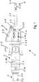
1 eine Seitenansicht der erfindungsgemäßen medizinischen Vorrichtung;2 eine Seitenansicht unter einem anderen Angularwinkel, teilweise geschnitten;3 die Seitendarstellung der Figur mit einem anderen Abstand in einen äußeren Teil zur Darstellung der Ausbildung eines unterhalb liegenden Teils;4 einen Längsschnitt durch die erfindungsgemäße Vorrichtung entsprechend AB der2 ;5 einen Längsschnitt unter einem Angularwinkel um 90° zum Schnitt der4 ; und6 eine vergrößerte Darstellung des Schwenkkopfs der2 .
1 a side view of the medical device according to the invention;2 a side view at a different Angularwinkel, partially cut;3 the side view of the figure with a different distance in an outer part to illustrate the formation of an underlying part;4 a longitudinal section through the device according to the invention according to AB of2 ;5 a longitudinal section at an Angularwinkel by 90 ° to the section of4 ; and6 an enlarged view of the swivel head of2 ,
Die erfindungsgemäße Vorrichtung
Mit dem Kopplungsteil
Einstückig mit dem ersten Kopplungsteil
Etwa mittig des Kopplungsteils
Relativ zum Führungsteil
Die Betätigungseinheit
Kurze Axialschlitze
Wie in
Wie in den
Wie in der
Die Längsschnitte der
Die Betätigung des Schwenkkopfes
Wird der zweite Zylindermantel
Damit wird erreicht, dass ein sich durch das Führungsrohr
In den
Das zweite Kopplungsteil
Die axiale Festlegung des Werkzeugs
ZITATE ENTHALTEN IN DER BESCHREIBUNG QUOTES INCLUDE IN THE DESCRIPTION
Diese Liste der vom Anmelder aufgeführten Dokumente wurde automatisiert erzeugt und ist ausschließlich zur besseren Information des Lesers aufgenommen. Die Liste ist nicht Bestandteil der deutschen Patent- bzw. Gebrauchsmusteranmeldung. Das DPMA übernimmt keinerlei Haftung für etwaige Fehler oder Auslassungen.This list of the documents listed by the applicant has been generated automatically and is included solely for the better information of the reader. The list is not part of the German patent or utility model application. The DPMA assumes no liability for any errors or omissions.
Zitierte PatentliteraturCited patent literature
- EP 2790596 B1 [0002]EP 2790596 B1 [0002]
- DE 10036108 A1 [0003]DE 10036108 A1 [0003]
- EP 2393435 [0013, 0015, 0029]EP 2393435 [0013, 0015, 0029]
Claims (17)
Translated fromGermanPriority Applications (9)
| Application Number | Priority Date | Filing Date | Title |
|---|---|---|---|
| DE102017010033.0ADE102017010033A1 (en) | 2017-10-27 | 2017-10-27 | Medical device |
| CA3078524ACA3078524C (en) | 2017-10-27 | 2018-08-23 | Medical device |
| ES18765554TES2892404T3 (en) | 2017-10-27 | 2018-08-23 | Medical device |
| EP18765554.3AEP3528688B1 (en) | 2017-10-27 | 2018-08-23 | Medical device |
| JP2020522721AJP7228272B2 (en) | 2017-10-27 | 2018-08-23 | medical device |
| US16/758,511US11331108B2 (en) | 2017-10-27 | 2018-08-23 | Medical device |
| KR1020207012346AKR102589449B1 (en) | 2017-10-27 | 2018-08-23 | Medical Equipment |
| CN201880066603.8ACN111212590B (en) | 2017-10-27 | 2018-08-23 | medical device |
| PCT/EP2018/000412WO2019081051A1 (en) | 2017-10-27 | 2018-08-23 | MEDICAL DEVICE |
Applications Claiming Priority (1)
| Application Number | Priority Date | Filing Date | Title |
|---|---|---|---|
| DE102017010033.0ADE102017010033A1 (en) | 2017-10-27 | 2017-10-27 | Medical device |
Publications (1)
| Publication Number | Publication Date |
|---|---|
| DE102017010033A1true DE102017010033A1 (en) | 2019-05-02 |
Family
ID=63517830
Family Applications (1)
| Application Number | Title | Priority Date | Filing Date |
|---|---|---|---|
| DE102017010033.0AWithdrawnDE102017010033A1 (en) | 2017-10-27 | 2017-10-27 | Medical device |
Country Status (9)
| Country | Link |
|---|---|
| US (1) | US11331108B2 (en) |
| EP (1) | EP3528688B1 (en) |
| JP (1) | JP7228272B2 (en) |
| KR (1) | KR102589449B1 (en) |
| CN (1) | CN111212590B (en) |
| CA (1) | CA3078524C (en) |
| DE (1) | DE102017010033A1 (en) |
| ES (1) | ES2892404T3 (en) |
| WO (1) | WO2019081051A1 (en) |
Cited By (7)
| Publication number | Priority date | Publication date | Assignee | Title |
|---|---|---|---|---|
| WO2023006541A1 (en) | 2021-07-27 | 2023-02-02 | Aesculap Ag | Bendable shaft for a medical hand-held instrument |
| DE102022107970A1 (en) | 2022-04-04 | 2023-10-05 | Aesculap Ag | Flexible surgical tool with integrated bearing assembly |
| DE102022107972A1 (en) | 2022-04-04 | 2023-10-05 | Aesculap Ag | Medical tool system |
| EP4321108A1 (en) | 2022-08-09 | 2024-02-14 | Aesculap AG | Motor handpiece with rotatable operating element and medical hand instrument |
| EP4321109A1 (en) | 2022-08-09 | 2024-02-14 | Aesculap AG | Medical motor hand piece with angle adjustment ring and medical hand instrument |
| EP4321107A1 (en) | 2022-08-09 | 2024-02-14 | Aesculap AG | Medical motor hand piece with a detent and/or fixing unit |
| DE102022119979A1 (en) | 2022-08-09 | 2024-02-15 | Aesculap Ag | Medical motor handpiece for 2-in-1 operation and medical hand instrument with 2-in-1 operation |
Families Citing this family (6)
| Publication number | Priority date | Publication date | Assignee | Title |
|---|---|---|---|---|
| EP4368128A3 (en) | 2016-09-07 | 2024-07-17 | Vertos Medical, Inc. | Percutaneous lateral recess resection methods and instruments |
| NL2019175B1 (en)* | 2017-07-04 | 2019-01-14 | Fortimedix Surgical B V | Steerable instrument comprising a radial spacers between coaxial cylindrical elements |
| DE102017010033A1 (en)* | 2017-10-27 | 2019-05-02 | Joimax Gmbh | Medical device |
| US11364130B2 (en) | 2020-09-01 | 2022-06-21 | Warsaw Orthopedic, Inc. | Spinal implant system and method |
| DE102021115486A1 (en) | 2021-06-15 | 2022-12-15 | Joimax Gmbh | Medical instrument, medical instrument set, medical device and medical procedure |
| US20230404561A1 (en) | 2022-06-16 | 2023-12-21 | Vertos Medical, Inc. | Integrated instrument assembly |
Citations (5)
| Publication number | Priority date | Publication date | Assignee | Title |
|---|---|---|---|---|
| DE10036108A1 (en) | 1999-09-09 | 2001-11-15 | Tuebingen Scient Surgical Prod | Surgical instrument for minimally invasive procedures |
| DE69837488T2 (en)* | 1997-09-24 | 2007-12-13 | Smith & Nephew, Inc., Memphis | STEERING SURGICAL INSTRUMENT |
| EP2393435A1 (en) | 2009-12-23 | 2011-12-14 | Joimax GmbH | Surgical instrument for detachably connecting a handpiece to a surgical tool |
| DE102010024136A1 (en)* | 2010-06-17 | 2011-12-22 | Olympus Winter & Ibe Gmbh | Uterus manipulator for use by surgeon for achieving access through vagina to remove uterus, has cap fixed at shaft by holder in length-adjustable manner, where holder includes detent device for displacement between detent positions |
| EP2790596A1 (en) | 2012-05-03 | 2014-10-22 | Joimax GmbH | Surgical tool device |
Family Cites Families (27)
| Publication number | Priority date | Publication date | Assignee | Title |
|---|---|---|---|---|
| GB8413058D0 (en)* | 1984-05-22 | 1984-06-27 | Minvade Ltd | Endoscopes |
| US5938616A (en)* | 1997-01-31 | 1999-08-17 | Acuson Corporation | Steering mechanism and steering line for a catheter-mounted ultrasonic transducer |
| US6312438B1 (en)* | 2000-02-01 | 2001-11-06 | Medtronic Xomed, Inc. | Rotary bur instruments having bur tips with aspiration passages |
| DE10156917B4 (en)* | 2001-11-21 | 2006-04-20 | Günter Bissinger Medizintechnik GmbH | Instrument for endoscopic surgery |
| ATE548067T1 (en)* | 2005-09-16 | 2012-03-15 | Riek Siegfried | MEDICAL INSTRUMENT |
| ATE459295T1 (en)* | 2007-07-20 | 2010-03-15 | Wolf Gmbh Richard | ENDOSCOPIC INSTRUMENT |
| US8394101B2 (en)* | 2009-02-23 | 2013-03-12 | Globus Medical, Inc. | Discectomy instrument |
| US8568417B2 (en)* | 2009-12-18 | 2013-10-29 | Charles River Engineering Solutions And Technologies, Llc | Articulating tool and methods of using |
| US8348950B2 (en)* | 2010-01-04 | 2013-01-08 | Zyga Technology, Inc. | Sacroiliac fusion system |
| EP2596741B1 (en)* | 2011-02-16 | 2015-06-10 | Olympus Medical Systems Corp. | Endoscope, and treatment instrument for endoscope |
| US9119639B2 (en)* | 2011-08-09 | 2015-09-01 | DePuy Synthes Products, Inc. | Articulated cavity creator |
| WO2013082310A1 (en) | 2011-12-02 | 2013-06-06 | Barosense, Inc. | Positioning device and articulation assembly for remote positioning of a tool |
| US20140135745A1 (en)* | 2011-12-15 | 2014-05-15 | Imricor Medical Systems, Inc. | Mri compatible handle and steerable sheath |
| EP3593740B1 (en)* | 2012-06-20 | 2021-10-06 | Stryker Corporation | System for off-axis tissue manipulation |
| US8986225B2 (en)* | 2012-08-02 | 2015-03-24 | Covidien Lp | Guidewire |
| JP6081578B2 (en)* | 2013-04-01 | 2017-02-15 | テルモ株式会社 | Actuating member and medical device |
| US10178998B2 (en)* | 2013-11-29 | 2019-01-15 | Chongqing Xishan Science & Technology Co., Ltd. | Lateral grinding drill with continuously variable angle and driving component thereof |
| EP3639767B1 (en)* | 2014-08-06 | 2024-07-03 | Stryker Corporation | Cutting accessory for use with a powered surgical handpiece |
| WO2016138443A2 (en)* | 2015-02-26 | 2016-09-01 | Stryker Corporation | Surgical instrument with articulation region |
| DE102015204946B4 (en)* | 2015-03-19 | 2017-02-09 | Eberle Gmbh & Co. Kg | Surgical instrument with fine positioning mechanism |
| WO2017164455A1 (en) | 2016-03-21 | 2017-09-28 | 황적희 | Detachable medical cutting tool |
| KR101628648B1 (en)* | 2016-03-21 | 2016-06-08 | 황적희 | Detachable medical cutting tools |
| CN206315109U (en)* | 2016-08-04 | 2017-07-11 | 彭惠莲 | A kind of operation abrasive drilling |
| CN206303925U (en)* | 2016-08-30 | 2017-07-07 | 重庆西山科技股份有限公司 | New reciprocating knife tool |
| US10660656B2 (en)* | 2017-01-06 | 2020-05-26 | Dfine, Inc. | Osteotome with a distal portion for simultaneous advancement and articulation |
| DE102017010033A1 (en)* | 2017-10-27 | 2019-05-02 | Joimax Gmbh | Medical device |
| US11510686B2 (en)* | 2018-07-05 | 2022-11-29 | Conmed Corporation | Retrograde drilling device |
- 2017
- 2017-10-27DEDE102017010033.0Apatent/DE102017010033A1/ennot_activeWithdrawn
- 2018
- 2018-08-23JPJP2020522721Apatent/JP7228272B2/enactiveActive
- 2018-08-23CACA3078524Apatent/CA3078524C/enactiveActive
- 2018-08-23KRKR1020207012346Apatent/KR102589449B1/enactiveActive
- 2018-08-23ESES18765554Tpatent/ES2892404T3/enactiveActive
- 2018-08-23WOPCT/EP2018/000412patent/WO2019081051A1/ennot_activeCeased
- 2018-08-23EPEP18765554.3Apatent/EP3528688B1/enactiveActive
- 2018-08-23CNCN201880066603.8Apatent/CN111212590B/enactiveActive
- 2018-08-23USUS16/758,511patent/US11331108B2/enactiveActive
Patent Citations (7)
| Publication number | Priority date | Publication date | Assignee | Title |
|---|---|---|---|---|
| DE69837488T2 (en)* | 1997-09-24 | 2007-12-13 | Smith & Nephew, Inc., Memphis | STEERING SURGICAL INSTRUMENT |
| DE10036108A1 (en) | 1999-09-09 | 2001-11-15 | Tuebingen Scient Surgical Prod | Surgical instrument for minimally invasive procedures |
| EP2393435A1 (en) | 2009-12-23 | 2011-12-14 | Joimax GmbH | Surgical instrument for detachably connecting a handpiece to a surgical tool |
| EP2393435B1 (en) | 2009-12-23 | 2012-12-05 | Joimax GmbH | Surgical instrument for detachably connecting a handpiece to a surgical tool |
| DE102010024136A1 (en)* | 2010-06-17 | 2011-12-22 | Olympus Winter & Ibe Gmbh | Uterus manipulator for use by surgeon for achieving access through vagina to remove uterus, has cap fixed at shaft by holder in length-adjustable manner, where holder includes detent device for displacement between detent positions |
| EP2790596A1 (en) | 2012-05-03 | 2014-10-22 | Joimax GmbH | Surgical tool device |
| EP2790596B1 (en) | 2012-05-03 | 2015-06-03 | Joimax GmbH | Surgical tool device |
Cited By (14)
| Publication number | Priority date | Publication date | Assignee | Title |
|---|---|---|---|---|
| WO2023006541A1 (en) | 2021-07-27 | 2023-02-02 | Aesculap Ag | Bendable shaft for a medical hand-held instrument |
| DE102021119386A1 (en) | 2021-07-27 | 2023-02-02 | Aesculap Ag | Bendable shaft for a medical hand instrument |
| DE102022107970A1 (en) | 2022-04-04 | 2023-10-05 | Aesculap Ag | Flexible surgical tool with integrated bearing assembly |
| DE102022107972A1 (en) | 2022-04-04 | 2023-10-05 | Aesculap Ag | Medical tool system |
| WO2023194131A1 (en) | 2022-04-04 | 2023-10-12 | Aesculap Ag | Medical tool system |
| WO2023194159A1 (en) | 2022-04-04 | 2023-10-12 | Aesculap Ag | Flexible surgical tool with integrated bearing assembly |
| EP4321108A1 (en) | 2022-08-09 | 2024-02-14 | Aesculap AG | Motor handpiece with rotatable operating element and medical hand instrument |
| EP4321109A1 (en) | 2022-08-09 | 2024-02-14 | Aesculap AG | Medical motor hand piece with angle adjustment ring and medical hand instrument |
| EP4321107A1 (en) | 2022-08-09 | 2024-02-14 | Aesculap AG | Medical motor hand piece with a detent and/or fixing unit |
| DE102022119980A1 (en) | 2022-08-09 | 2024-02-15 | Aesculap Ag | Medical motor handpiece with locking and/or stop unit |
| DE102022119979A1 (en) | 2022-08-09 | 2024-02-15 | Aesculap Ag | Medical motor handpiece for 2-in-1 operation and medical hand instrument with 2-in-1 operation |
| DE102022119982A1 (en) | 2022-08-09 | 2024-02-15 | Aesculap Ag | Motor handpiece with rotatable control element and medical hand instrument |
| DE102022119983A1 (en) | 2022-08-09 | 2024-02-15 | Aesculap Ag | Medical motor handpiece with angle adjusting ring and medical hand instrument |
| WO2024033228A1 (en) | 2022-08-09 | 2024-02-15 | Aesculap Ag | Medical motor handpiece for 2-in-1 operation and medical manual instrument with 2-in-1 operation |
Also Published As
| Publication number | Publication date |
|---|---|
| US20200253622A1 (en) | 2020-08-13 |
| CN111212590A (en) | 2020-05-29 |
| WO2019081051A1 (en) | 2019-05-02 |
| JP7228272B2 (en) | 2023-02-24 |
| ES2892404T3 (en) | 2022-02-04 |
| US11331108B2 (en) | 2022-05-17 |
| JP2021500150A (en) | 2021-01-07 |
| EP3528688A1 (en) | 2019-08-28 |
| CA3078524C (en) | 2024-04-16 |
| CA3078524A1 (en) | 2019-05-02 |
| CN111212590B (en) | 2023-11-14 |
| KR102589449B1 (en) | 2023-10-16 |
| KR20200079498A (en) | 2020-07-03 |
| EP3528688B1 (en) | 2021-07-28 |
Similar Documents
| Publication | Publication Date | Title |
|---|---|---|
| EP3528688B1 (en) | Medical device | |
| DE10358554B4 (en) | Surgical instrument for dissecting bones or other tissue with telescopic attachment | |
| EP0671149B1 (en) | Device for placing an anastomosis ring | |
| DE102009025487B4 (en) | Self-tightening chuck with axial locking | |
| EP2792439B1 (en) | Quick change system for a tool holder | |
| EP2561816B1 (en) | Tool for a micro-invasive surgical instrument | |
| DE29504857U1 (en) | Drilling jig for surgical drilling tools | |
| DE69324685T2 (en) | ADJUSTABLE GRIPPER | |
| EP3000404B1 (en) | Medical instrument and coupling device for connecting two components of a medical instrument | |
| EP2982880A2 (en) | Device for self-locking bidirectional drive of a medical treatment device | |
| EP2090385A2 (en) | Device for expanding conduits | |
| EP2090384A2 (en) | Device for expanding conduits | |
| DE3711377A1 (en) | SURGICAL INSTRUMENT | |
| DE202009017470U1 (en) | Surgical instrument for releasably connecting a handpiece with a surgical tool | |
| EP1922004A1 (en) | Screwdriver for bone screws | |
| EP0732892A1 (en) | Tubular-handled surgical instrument | |
| EP1709931B1 (en) | Motor element, in particular dental hand piece with a releasable coupling for a tool holder | |
| EP1709930A1 (en) | Motor element, in particular medical handpice with a collet | |
| WO2004082492A1 (en) | Cutting and forming device | |
| DE102009049317B4 (en) | Surgical instrument | |
| DE10014401C2 (en) | Puller for loosening individual parts of an endoprosthesis | |
| DE1491029A1 (en) | Dental handpiece | |
| EP4504075A1 (en) | Medical tool system | |
| DE202006006914U1 (en) | Surgical cutting instrument, comprising rotating cutting device only partly exposed at lower end | |
| DE102022116372B4 (en) | SURGICAL INSTRUMENT AND METHOD FOR DISASSEMBLY THEREOF |
Legal Events
| Date | Code | Title | Description |
|---|---|---|---|
| R163 | Identified publications notified | ||
| R119 | Application deemed withdrawn, or ip right lapsed, due to non-payment of renewal fee |