DE102017008148A1 - Sensor unit, intraoperative navigation system and method for detecting a surgical instrument - Google Patents
Sensor unit, intraoperative navigation system and method for detecting a surgical instrumentDownload PDFInfo
- Publication number
- DE102017008148A1 DE102017008148A1DE102017008148.4ADE102017008148ADE102017008148A1DE 102017008148 A1DE102017008148 A1DE 102017008148A1DE 102017008148 ADE102017008148 ADE 102017008148ADE 102017008148 A1DE102017008148 A1DE 102017008148A1
- Authority
- DE
- Germany
- Prior art keywords
- endoscope
- unit
- distal end
- coils
- hollow needle
- Prior art date
- Legal status (The legal status is an assumption and is not a legal conclusion. Google has not performed a legal analysis and makes no representation as to the accuracy of the status listed.)
- Withdrawn
Links
Images


Classifications
- A—HUMAN NECESSITIES
- A61—MEDICAL OR VETERINARY SCIENCE; HYGIENE
- A61B—DIAGNOSIS; SURGERY; IDENTIFICATION
- A61B1/00—Instruments for performing medical examinations of the interior of cavities or tubes of the body by visual or photographical inspection, e.g. endoscopes; Illuminating arrangements therefor
- A61B1/00064—Constructional details of the endoscope body
- A61B1/00071—Insertion part of the endoscope body
- A61B1/0008—Insertion part of the endoscope body characterised by distal tip features
- A61B1/00087—Tools
- A—HUMAN NECESSITIES
- A61—MEDICAL OR VETERINARY SCIENCE; HYGIENE
- A61B—DIAGNOSIS; SURGERY; IDENTIFICATION
- A61B1/00—Instruments for performing medical examinations of the interior of cavities or tubes of the body by visual or photographical inspection, e.g. endoscopes; Illuminating arrangements therefor
- A61B1/00147—Holding or positioning arrangements
- A61B1/00158—Holding or positioning arrangements using magnetic field
- A—HUMAN NECESSITIES
- A61—MEDICAL OR VETERINARY SCIENCE; HYGIENE
- A61B—DIAGNOSIS; SURGERY; IDENTIFICATION
- A61B1/00—Instruments for performing medical examinations of the interior of cavities or tubes of the body by visual or photographical inspection, e.g. endoscopes; Illuminating arrangements therefor
- A61B1/00064—Constructional details of the endoscope body
- A61B1/00071—Insertion part of the endoscope body
- A61B1/0008—Insertion part of the endoscope body characterised by distal tip features
- A61B1/00097—Sensors
- A—HUMAN NECESSITIES
- A61—MEDICAL OR VETERINARY SCIENCE; HYGIENE
- A61B—DIAGNOSIS; SURGERY; IDENTIFICATION
- A61B1/00—Instruments for performing medical examinations of the interior of cavities or tubes of the body by visual or photographical inspection, e.g. endoscopes; Illuminating arrangements therefor
- A61B1/00112—Connection or coupling means
- A61B1/00121—Connectors, fasteners and adapters, e.g. on the endoscope handle
- A61B1/00124—Connectors, fasteners and adapters, e.g. on the endoscope handle electrical, e.g. electrical plug-and-socket connection
- A—HUMAN NECESSITIES
- A61—MEDICAL OR VETERINARY SCIENCE; HYGIENE
- A61B—DIAGNOSIS; SURGERY; IDENTIFICATION
- A61B1/00—Instruments for performing medical examinations of the interior of cavities or tubes of the body by visual or photographical inspection, e.g. endoscopes; Illuminating arrangements therefor
- A61B1/00112—Connection or coupling means
- A61B1/00121—Connectors, fasteners and adapters, e.g. on the endoscope handle
- A61B1/00128—Connectors, fasteners and adapters, e.g. on the endoscope handle mechanical, e.g. for tubes or pipes
- A—HUMAN NECESSITIES
- A61—MEDICAL OR VETERINARY SCIENCE; HYGIENE
- A61B—DIAGNOSIS; SURGERY; IDENTIFICATION
- A61B1/00—Instruments for performing medical examinations of the interior of cavities or tubes of the body by visual or photographical inspection, e.g. endoscopes; Illuminating arrangements therefor
- A61B1/00131—Accessories for endoscopes
- A61B1/00135—Oversleeves mounted on the endoscope prior to insertion
- A—HUMAN NECESSITIES
- A61—MEDICAL OR VETERINARY SCIENCE; HYGIENE
- A61B—DIAGNOSIS; SURGERY; IDENTIFICATION
- A61B1/00—Instruments for performing medical examinations of the interior of cavities or tubes of the body by visual or photographical inspection, e.g. endoscopes; Illuminating arrangements therefor
- A61B1/005—Flexible endoscopes
- A61B1/0051—Flexible endoscopes with controlled bending of insertion part
- A—HUMAN NECESSITIES
- A61—MEDICAL OR VETERINARY SCIENCE; HYGIENE
- A61B—DIAGNOSIS; SURGERY; IDENTIFICATION
- A61B1/00—Instruments for performing medical examinations of the interior of cavities or tubes of the body by visual or photographical inspection, e.g. endoscopes; Illuminating arrangements therefor
- A61B1/005—Flexible endoscopes
- A61B1/01—Guiding arrangements therefore
- A—HUMAN NECESSITIES
- A61—MEDICAL OR VETERINARY SCIENCE; HYGIENE
- A61B—DIAGNOSIS; SURGERY; IDENTIFICATION
- A61B1/00—Instruments for performing medical examinations of the interior of cavities or tubes of the body by visual or photographical inspection, e.g. endoscopes; Illuminating arrangements therefor
- A61B1/012—Instruments for performing medical examinations of the interior of cavities or tubes of the body by visual or photographical inspection, e.g. endoscopes; Illuminating arrangements therefor characterised by internal passages or accessories therefor
- A—HUMAN NECESSITIES
- A61—MEDICAL OR VETERINARY SCIENCE; HYGIENE
- A61B—DIAGNOSIS; SURGERY; IDENTIFICATION
- A61B1/00—Instruments for performing medical examinations of the interior of cavities or tubes of the body by visual or photographical inspection, e.g. endoscopes; Illuminating arrangements therefor
- A61B1/313—Instruments for performing medical examinations of the interior of cavities or tubes of the body by visual or photographical inspection, e.g. endoscopes; Illuminating arrangements therefor for introducing through surgical openings, e.g. laparoscopes
- A61B1/3135—Instruments for performing medical examinations of the interior of cavities or tubes of the body by visual or photographical inspection, e.g. endoscopes; Illuminating arrangements therefor for introducing through surgical openings, e.g. laparoscopes for examination of the epidural or the spinal space
- A—HUMAN NECESSITIES
- A61—MEDICAL OR VETERINARY SCIENCE; HYGIENE
- A61B—DIAGNOSIS; SURGERY; IDENTIFICATION
- A61B17/00—Surgical instruments, devices or methods
- A61B17/34—Trocars; Puncturing needles
- A61B17/3472—Trocars; Puncturing needles for bones, e.g. intraosseus injections
- A—HUMAN NECESSITIES
- A61—MEDICAL OR VETERINARY SCIENCE; HYGIENE
- A61B—DIAGNOSIS; SURGERY; IDENTIFICATION
- A61B34/00—Computer-aided surgery; Manipulators or robots specially adapted for use in surgery
- A61B34/20—Surgical navigation systems; Devices for tracking or guiding surgical instruments, e.g. for frameless stereotaxis
- A—HUMAN NECESSITIES
- A61—MEDICAL OR VETERINARY SCIENCE; HYGIENE
- A61B—DIAGNOSIS; SURGERY; IDENTIFICATION
- A61B5/00—Measuring for diagnostic purposes; Identification of persons
- A61B5/06—Devices, other than using radiation, for detecting or locating foreign bodies ; Determining position of diagnostic devices within or on the body of the patient
- A61B5/061—Determining position of a probe within the body employing means separate from the probe, e.g. sensing internal probe position employing impedance electrodes on the surface of the body
- A61B5/062—Determining position of a probe within the body employing means separate from the probe, e.g. sensing internal probe position employing impedance electrodes on the surface of the body using magnetic field
- A—HUMAN NECESSITIES
- A61—MEDICAL OR VETERINARY SCIENCE; HYGIENE
- A61B—DIAGNOSIS; SURGERY; IDENTIFICATION
- A61B90/00—Instruments, implements or accessories specially adapted for surgery or diagnosis and not covered by any of the groups A61B1/00 - A61B50/00, e.g. for luxation treatment or for protecting wound edges
- A—HUMAN NECESSITIES
- A61—MEDICAL OR VETERINARY SCIENCE; HYGIENE
- A61B—DIAGNOSIS; SURGERY; IDENTIFICATION
- A61B34/00—Computer-aided surgery; Manipulators or robots specially adapted for use in surgery
- A61B34/20—Surgical navigation systems; Devices for tracking or guiding surgical instruments, e.g. for frameless stereotaxis
- A61B2034/2046—Tracking techniques
- A61B2034/2051—Electromagnetic tracking systems
Landscapes
- Health & Medical Sciences (AREA)
- Life Sciences & Earth Sciences (AREA)
- Surgery (AREA)
- Engineering & Computer Science (AREA)
- Veterinary Medicine (AREA)
- Public Health (AREA)
- General Health & Medical Sciences (AREA)
- Animal Behavior & Ethology (AREA)
- Molecular Biology (AREA)
- Biomedical Technology (AREA)
- Heart & Thoracic Surgery (AREA)
- Medical Informatics (AREA)
- Nuclear Medicine, Radiotherapy & Molecular Imaging (AREA)
- Pathology (AREA)
- Physics & Mathematics (AREA)
- Biophysics (AREA)
- Radiology & Medical Imaging (AREA)
- Optics & Photonics (AREA)
- Mechanical Engineering (AREA)
- Robotics (AREA)
- Oral & Maxillofacial Surgery (AREA)
- Orthopedic Medicine & Surgery (AREA)
- Neurology (AREA)
- Human Computer Interaction (AREA)
- Endoscopes (AREA)
- Instruments For Viewing The Inside Of Hollow Bodies (AREA)
- Measurement Of Length, Angles, Or The Like Using Electric Or Magnetic Means (AREA)
Abstract
Translated fromGermanDescription
Translated fromGermanDie Erfindung betrifft eine Sensoreinheit mit zwei mit festem Längsabstand zueinander angeordneten Spulen aus elektrisch leitfähigem Metalldraht, ein intraoperatives Navigationssystem mit einer Steuer- und Verarbeitungselektronik und einer mit dieser elektrisch verbindbaren Sensoreinheit mit zwei mit festem Längsabstand zueinander angeordneten Spulen aus elektrisch leitfähigem Metalldraht sowie ein Verfahren zur Detektion eines chirurgischen Instruments, wie einer Hohlnadel, und/oder eines Endoskops.The invention relates to a sensor unit with two fixed longitudinally spaced coils of electrically conductive metal wire, an intraoperative navigation system with a control and processing electronics and an electrically connectable with this sensor unit with two fixed longitudinally spaced coils of electrically conductive metal wire and a method for Detection of a surgical instrument, such as a hollow needle, and / or an endoscope.
Minimal-invasive Operationen werden heute bereits mittels navigationsgestützter Operationsverfahren durchgeführt. Es werden hierzu unterschiedliche Navigationssysteme eingesetzt. Es kommen aktive und passive Systeme zum Einsatz. Bei aktiven Systemen ist ein in den Körper eines Patienten eingebrachtes Teil, wie ein Instrument oder chirurgisches Werkzeug mit einem Sender versehen, über den sich extern die Position des Instruments oder Werkzeugs, insbesondere des distalen am Eingriffsort befindlichen Endes bestimmen lässt.Minimally invasive operations are already performed by means of navigation-based surgical procedures. Different navigation systems are used for this purpose. Active and passive systems are used. In active systems, a part inserted into the body of a patient, such as an instrument or surgical tool, is provided with a transmitter via which the position of the instrument or tool, in particular the distal end located at the site of the intervention, can be determined externally.
Bei passiven Systemen sind neben optischen Systemen zur Positionierung eines chirurgischen Instruments, insbesondere von dessen distalem Ende auch elektromagnetische Systeme bekannt. Bei der elektromagnetischen Navigation wird durch einen Feldgenerator ein inhomogenes elektromagnetisches Feld erzeugt, welches über einen oder mehrere Sensoren erfasst wird, wodurch wiederum die Position und Ausrichtung des Instruments oder chirurgischen Werkzeugs, insbesondere dessen distales Ende, direkt oder indirekt erfasst werden kann. Direkte Erfassung des distalen Endes eines chirurgischen Teils beinhaltet die Anordnung des Sensors am distalen Ende des Teils selbst; indirekte Erfassung beinhaltet die feste starre Anbringung des Sensors in einer definierten Stelle, insbesondere Axialposition, an dem chirurgischen Teil. Aufgrund des gemessenen Sensorsignals können Rückschluss auf die Position und gegebenenfalls Ausrichtung des distalen Endes gesehen werden. Bei der passiven Navigation hat sich insbesondere die elektromagnetische Navigation bewährt, bei der ein elektromagnetisches Feld extern um den Operationsbereich, beispielsweise durch einen Erzeuger eines elektromagnetischen Feldes in einem Kissen, auf dem der Patient liegt, erzeugt wird. Im chirurgischen Instrument eingebaute spulenartige Sensoren ermöglichen die Ortung der Instrumente, woraufhin eine Darstellung in CT- oder MRT-Bildern erfolgen kann. Dieses Verfahren beinhaltet keine Strahlenbelastung und reduziert insgesamt so die Strahlenbelastung, auch durch einen reduzierten Röntgeneinsatz. Es wird weder die Bildqualität beeinträchtigt, noch können Sensoren, da es eben keine optischen Sensoren sind, verdeckt werden. Die Bewegungsfreiheit des Operateurs wird nicht eingeschränkt, wie es bei optischen Systemen der Fall ist.In passive systems, in addition to optical systems for positioning a surgical instrument, in particular its distal end and electromagnetic systems are known. In electromagnetic navigation, an inhomogeneous electromagnetic field is generated by a field generator, which is detected by one or more sensors, which in turn the position and orientation of the instrument or surgical tool, in particular its distal end, can be detected directly or indirectly. Direct detection of the distal end of a surgical part involves locating the sensor at the distal end of the part itself; Indirect detection involves the fixed rigid mounting of the sensor in a defined position, in particular axial position, on the surgical part. Due to the measured sensor signal, conclusions can be drawn about the position and if necessary orientation of the distal end. In passive navigation, in particular, the electromagnetic navigation has proved useful in which an electromagnetic field is generated externally around the operating area, for example by a generator of an electromagnetic field in a pad on which the patient lies. Coil-type sensors built into the surgical instrument allow the instruments to be located and then displayed in CT or MRI images. This procedure does not involve radiation exposure and thus reduces overall radiation exposure, even through reduced X-ray use. It does not affect the image quality, nor can sensors be obscured because they are not optical sensors. The freedom of movement of the surgeon is not restricted, as is the case with optical systems.
Der Erfindung liegt die Aufgabe zugrunde, eine Sensoreinheit und ein Navigationssystem zu schaffen, die eine automatische Detektion der Art des chirurgischen Instruments und eine entsprechende angepasste Anzeige auf einem Monitor für den Operateur bewirken.The invention has for its object to provide a sensor unit and a navigation system, which cause an automatic detection of the type of surgical instrument and a corresponding customized display on a monitor for the surgeon.
Die Erfindung sieht im Hinblick auf die Lösung der genannten Aufgabe eine Sensoreinheit mit zwei mit festem Längsabstand zueinander angeordneten Spulen aus elektrisch leitfähigem Metalldraht und mit einem beide umgebenden flexiblen Schutzschlauch vor. Weiterhin wird die Aufgabe durch ein intraoperatives Navigationssystem mit einer Steuer- und Verarbeitungselektronik und mit mindestens einer mit dieser elektrisch verbindbaren Sensoreinheit der vorgenannten Art gelöst, bei dem die Steuer- und Verarbeitungselektronik eine Detektionseinheit, eine Navigationseinheit und ein Kamerasystem aufweist. Schließlich ist zur Lösung der genannten Aufgabe ein Verfahren zur Detektion eines chirurgischen Instruments, wie einer Hohlnadel und/oder eines Endoskops vorgesehen, bei dem die Winkelausrichtung zweier mit festem Längsabstand zueinander angeordneter Spulen aus Metalldraht einer Sensoreinheit bestimmt wird.With regard to the solution of the stated object, the invention provides a sensor unit with two coils of electrically conductive metal wire which are arranged at a fixed longitudinal distance from one another and with a flexible protective hose which surrounds both. Furthermore, the object is achieved by an intraoperative navigation system with control and processing electronics and with at least one electrically connectable sensor unit of the aforementioned type, in which the control and processing electronics have a detection unit, a navigation unit and a camera system. Finally, a method for detecting a surgical instrument, such as a hollow needle and / or an endoscope is provided for solving the above object, in which the angular orientation of two fixed longitudinally spaced coils of metal wire of a sensor unit is determined.
Typische Operations-Instrumente oder -Geräte sind solche, die durch eine rotationssymmetrische Hohlnadel distal zum Operationsort geführt werden oder aber Endoskope mit einem abgewinkelten Einlasseinsatz, wie einem Spülanschluss. Die erfindungsgemäße Sensoreinheit ist bei Anordnung in der erstgenannten Hohlnadel gestreckt, wodurch die beiden Sensorspulen axial hintereinander angeordnet und ausgerichtet sind, also der Winkel zwischen ihnen Null ist. Demgegenüber befindet sich bei Anordnung der entsprechenden Sensoreinheit in einem Endoskop die distale Spule am distalen Ende des Schafts des Endoskops, während die proximale Spule in einem Einlassansatz des Endoskops angeordnet ist und damit zur Achse des Schafts des Endoskops einen Winkel einschließt und daher auch zu der am distalen Ende vorgesehenen Spule. Damit besteht ein Relativwinkel zwischen beiden Spulen.Typical surgical instruments or devices are those that are guided by a rotationally symmetrical hollow needle distal to the surgical site or endoscopes with an angled inlet insert, such as a flushing port. The sensor unit according to the invention is stretched in the arrangement in the first-mentioned hollow needle, whereby the two sensor coils are axially arranged one behind the other and aligned, so the angle between them is zero. In contrast, when the corresponding sensor unit is arranged in an endoscope, the distal coil is located at the distal end of the shaft of the endoscope, while the proximal coil is arranged in an inlet shoulder of the endoscope and thus forms an angle to the axis of the shaft of the endoscope and therefore also to the distal end provided coil. This results in a relative angle between the two coils.
Die vorgenannten Unterschiede der Relativausrichtung der Spulen können durch ein elektronisches System detektiert werden und bilden daher die Voraussetzung zur Detektion der Art des chirurgischen Instruments oder Geräts, in dem die Sensoreinheit angeordnet ist.The aforementioned differences in the relative orientation of the coils can be detected by an electronic system and therefore form the prerequisite for the detection of the type of surgical instrument or device in which the sensor unit is arranged.
Die Detektion und Weiterverarbeitung der detektierten Information geschieht durch das genannte erfindungsgemäße intraoperative Operationssystem, indem diese die Relativausrichtung der beiden Spulen detektiert und eine Bildschirmanzeige auf einem Monitor für den Operateur derart steuert, dass das oder die für das jeweilige Instrument oder Gerät geeigneten Bilder angezeigt werden.The detection and further processing of the detected information is done by the said intraoperative surgical system according to the invention, by the relative orientation of the two Coils detected and controls a screen display on a monitor for the surgeon so that the one or more appropriate for the instrument or device images are displayed.
Mittels einer rotationssymmetrischen Hohlnadel wird ein Zugang zu einem Operationsgebiet im Körper eines Patienten geschaffen, so dass anschließend in an sich bekannter Weise Operationsinstrumente eingeführt werden können und eine solche Nadel detektiert wird, durch die geeignete Arbeitsinstrumente eingeführt werden, werden automatisch neben jeweils einem sagittalen, koronalen und axialen CT-, MRT- oder Röntgen-Bild des Wirbelsäulenbereichs, insbesondere der Wirbelsäule und genauer des Orts der Wirbelsäule, bei dem sich das Operationsgebiet befindet, zusammen mit der diesem Bild überorts- und orientierungsgerechten Überlagerung der Nadel bzw. Nadelspitze zusätzlich ein Bild entsprechend der Führungsrichtung der Hohlnadel und damit des einzusetzenden Arbeitsinstruments angezeigt, beispielsweise durch einen von der sonstigen Darstellung des Bildes deutlich abgehobenen Kreis als Projektion der Hohlnadelspitze auf den Operationsort als Orientierungshilfe zur richtigen Positionierung des Instruments.By means of a rotationally symmetrical hollow needle access to an operating area in the body of a patient is created, so that in a conventional manner operating instruments can be introduced and such a needle is detected, are introduced by the appropriate working instruments are automatically next to each a sagittal, coronal and axial CT, MRI or X-ray image of the spinal area, in particular of the spine and more precisely the location of the spine, in which the operating area is located, together with the over-location and orientation-appropriate superposition of the needle or needle tip this image in addition an image accordingly the guiding direction of the hollow needle and thus of the working instrument to be used displayed, for example, by a clearly lifted from the other representation of the image circle as a projection of the hollow needle tip on the surgical site as a guide to the correct position instrumentation.
Demgegenüber wird bei Erkennung eines Endoskops als chirurgischem Instrument oder Gerät neben den genannten sagittalen, koronalen und axialen Röntgenbildern mit überlagerter orts- und orientierungsgenauer Einblendung des Endoskopschaftes in das Röntgenbild zusätzlich automatisch das durch eine Kamera im Endoskop aufgenommene Bild des Operationsgebietes am Monitor des Operateurs angezeigt.In contrast, when detecting an endoscope as a surgical instrument or device in addition to the aforementioned sagittal, coronal and axial X-ray images with superimposed localization and orientation exact overlay of the endoscope shaft in the X-ray image automatically recorded by a camera in the endoscope image of the operating area displayed on the monitor of the surgeon.
Weiterbildungen der erfindungsgemäßen Sensoreinheit sehen vor, dass die Spulen aus Kupfer bestehen. Gleiches gilt für Verbindungsleitungen der Spulen zu einem - proximalen - Kontaktstecker.Further developments of the sensor unit according to the invention provide that the coils consist of copper. The same applies to connection lines of the coils to a - proximal - contact plug.
Weiterhin ist in bevorzugter Ausgestaltung bei einer Sensoreinheit vorgesehen, dass der Schutzschlauch aus sterilisierbarem, vorzugsweise biokompatiblem Kunststoff, wie Polyether besteht.Furthermore, it is provided in a preferred embodiment in a sensor unit, that the protective tube made of sterilizable, preferably biocompatible plastic, such as polyether.
Zur exakten Festlegung der Sensoreinheit an dem chirurgischen Instrument oder Gerät wird ein Luer-Adapter vorgesehen, der, wie bekannt, üblicherweise aus einem weiblichen und einem männlichen Adapterteil besteht. Demgemäß ist eine Sensoreinheit vorzugsweise dadurch ausgebildet, dass proximal der proximalen Spule ein Luer-Adapterteil angeordnet ist. Dieses besteht vorzugsweise aus Kunststoff, wie sterilisierbarem, biokompatiblem Kunststoff, insbesondere Nylon.For exact determination of the sensor unit to the surgical instrument or device, a Luer adapter is provided, which, as is known, usually consists of a female and a male adapter part. Accordingly, a sensor unit is preferably formed by a Luer adapter part being arranged proximally of the proximal coil. This is preferably made of plastic, such as sterilizable, biocompatible plastic, especially nylon.
Eine bevorzugte Ausgestaltung der Sensoreinheit zeichnet sich durch Verbindungsleitungen, insbesondere zur Verbindung mit einer Steuer- und Verarbeitungselektronik aus, in dem Anschlussleitungen der Spulen verlaufen.A preferred embodiment of the sensor unit is characterized by connecting lines, in particular for connection to a control and processing electronics, run in the connecting lines of the coils.
Das Navigationssystem weist vorzugsweise einen Monitor zur Anzeige der entsprechenden Darstellungen auf.The navigation system preferably has a monitor for displaying the corresponding representations.
Das Navigationssystem ist vorzugsweise weitergebildet durch Ausbildung zur Darstellung einer Hohlnadel, insbesondere deren distalen Endes überlagert auf einem Bild eines Wirbelsäulenbereichs eines Patienten im Bereich des distalen Endes der Hohlnadel und/oder durch Ausbildung zur Darstellung eines Endoskops, insbesondere dessen distalen Endes überlagert auf einem Bild von einem Wirbelsäulenbereich eines Patienten im Bereich der des distalen Endes des Endoskops. Schließlich ist eine bevorzugte Weiterbildung des Navigationssystems gekennzeichnet durch Ausbildung zur Darstellung von Hohlnadel und/oder Endoskop, insbesondere derer distalen Enden in mehreren Sichtweisen, insbesondere in Führungssicht entlang der Erstreckung der Nadel oder eines Schafts des Endoskops, sagittal, koronal und axial.The navigation system is preferably further developed by a design for imaging a hollow needle, in particular its distal end superimposed on an image of a spinal region of a patient in the region of the distal end of the hollow needle and / or by forming an endoscope, in particular its distal end superimposed on an image of a spinal region of a patient in the region of the distal end of the endoscope. Finally, a preferred embodiment of the navigation system is characterized by training for the representation of hollow needle and / or endoscope, in particular those distal ends in several views, especially in guide view along the extension of the needle or a shaft of the endoscope, sagittal, coronal and axial.
Weiterbildungen des erfindungsgemäßen Verfahrens sehen vor, dass die Winkelausrichtung zweier mit festem Längsabstand zueinander angeordneter Spulen aus Metalldraht einer Sensoreinheit bestimmt wird und/oder dass bei Detektion einer relativen axialen Ausrichtung der beiden Spulen eine Hohlnadel erkannt und eine Darstellung einer Hohlnadel, insbesondere deren distalen Endes überlagert auf einem Bild eines Wirbelsäulenbereichs eines Patienten im Bereich des distalen Endes der Hohlnadel bewirkt wird.Developments of the method according to the invention provide that the angular orientation of two fixed longitudinally spaced coils of metal wire of a sensor unit is determined and / or that detected upon detection of a relative axial alignment of the two coils, a hollow needle and a representation of a hollow needle, in particular its distal end superimposed is effected on an image of a spinal region of a patient in the region of the distal end of the hollow needle.
Das Endoskop wird über die Steuereinheit des Kamerasystems gesteuert und gibt ein Bild an die Verarbeitungseinheit des Kamerasystems. Dieses Bild wird an das Navigationssystem übertragen.The endoscope is controlled by the control unit of the camera system and gives an image to the processing unit of the camera system. This image is transmitted to the navigation system.
Das Navigationssystem bestehend aus verschiedenen funktionellen Softwarekomponenten, der Verarbeitungseinheit, der Steuereinheit und dem Feldgenerator, ist mit dem Kamerasystem und der Sensoreinheit sowie dem Monitor zur Anzeige verbunden. Die Sensoreinheit kann entweder zur Navigation eines rotationssymmetrischen Instruments oder einem Endoskop eingesetzt werden, indem diese entweder in den Schaft des Instruments oder in den Spülkanal des Endoskops eingeführt wird.The navigation system, consisting of various functional software components, the processing unit, the control unit and the field generator, is connected to the camera system and the sensor unit as well as the monitor for display. The sensor unit can either be used to navigate a rotationally symmetrical instrument or an endoscope by inserting it either into the shaft of the instrument or into the irrigation channel of the endoscope.
Der Feldgenerator erzeugt ein elektromagnetisches, inhomogenes Feld und wird über die Steuereinheit des Navigationssystems gesteuert. Die Signale der Sensorspulen des Drahtsensors werden über die Verarbeitungseinheit digitalisiert und über die funktionellen Softwarekomponenten ausgewertet. Die Funktionseinheit Instrumentenerkennung wertet die Signale der beiden Sensorspulen aus und erkennt anhand der Ausrichtung der beiden Spulen zueinander, ob die Sensoreinheit sich in einem Endoskop befindet oder nicht. Das Ergebnis gibt die Funktionseinheit Instrumentenerkennung an die Funktionseinheit Layout-Steuerung weiter. In Abhängigkeit ob die Navigationssoftware ein Endoskop erkennt oder nicht, wird über die Layout-Steuerung das entsprechende Layout auf dem Monitor dargestellt. Wird das Endoskop von der Software erkannt, wird das Videosignal über die Funktionseinheit in das Navigationssystem eingespeist und der Funktionseinheit für die Layout-Ausgabe zur Verfügung gestellt.The field generator generates an electromagnetic, inhomogeneous field and is controlled by the control unit of the navigation system. The signals of the sensor coils of the wire sensor are digitized via the processing unit and via the functional software components evaluated. The instrument recognition function unit evaluates the signals of the two sensor coils and, based on the orientation of the two coils relative to one another, detects whether the sensor unit is located in an endoscope or not. The result forwards the instrument recognition function unit to the layout control functional unit. Depending on whether the navigation software recognizes an endoscope or not, the corresponding layout is displayed on the monitor via the layout control. If the software recognizes the endoscope, the video signal is fed via the functional unit into the navigation system and made available to the functional unit for the layout output.
Wird kein Endoskop auf Basis der genau definierten Ausrichtung der beiden Sensorspulen zueinander über die entsprechende Funktionseinheit erkannt, wird ein rotationssymmetrisches Instrument und die entsprechende Layout-Darstellung ausgegeben.If no endoscope is detected on the basis of the precisely defined orientation of the two sensor coils relative to one another via the corresponding functional unit, a rotationally symmetrical instrument and the corresponding layout display are output.
Der Ablauf des erfindungsgemäßen Verfahrens ist vorzugsweise folgender:The sequence of the method according to the invention is preferably as follows:
Nach Starten der Navigationseinheit werden die Signale der Sensorik abgefragt. Sobald der Anwender die Sensoreinheit in das Arbeitsfeld des Feldgenerators bringt, kann ein Signal erkannt und gemessen werden. Ist das Sensorsignal ungleich dem Wert Null (Drahtsensor im Arbeitsfeld), erfolgt eine Instrumentenerkennung. Hierfür wird die Ausrichtung der beiden Sensorspulen ausgewertet. Sind dabei die beiden Spulen zueinander entsprechend der Geometrie des Spülkanals eines Endoskops, d.h. mit Relativwinkel ungleich Null ausgerichtet (Abstand und Winkel), wird dies von der Software erkannt und entsprechend das Endoskop als navigiertes Instrument angezeigt. Des Weiteren wird eine Layout-Anpassung vorgenommen. Wurde das Endoskop als navigiertes Instrument erkannt, wird insbesondere das Signal der proximalen Spule genutzt um die Position des Endoskops im Arbeitsfeld zu messen und somit die Position relativ zum Bilddatensatz des Patienten anzuzeigen. Ist die Ausrichtung der beiden Sensorspulen ungleich der genau definierten einer in den Spülkanal des Endoskops eingeführten Sensoreinheit, wird ein rotationssymmetrisches Instrument (Hohlnadel) zusammen mit der entsprechenden Layout-Darstellung von der Navigationseinheit ausgegeben. Das Signal des distalen Drahtsensors wird zur Bestimmung der Instrumentenlage im Arbeitsfeld genutzt und entsprechend im Bilddatensatz des Patienten angezeigt.After starting the navigation unit, the signals of the sensors are interrogated. As soon as the user brings the sensor unit into the working field of the field generator, a signal can be detected and measured. If the sensor signal is not equal to the value zero (wire sensor in the working field), an instrument recognition takes place. For this purpose, the alignment of the two sensor coils is evaluated. Are the two coils to each other according to the geometry of the flushing channel of an endoscope, i. aligned with relative angles not equal to zero (distance and angle), this is detected by the software and the endoscope is displayed as a navigated instrument accordingly. Furthermore, a layout adjustment is made. If the endoscope was recognized as a navigated instrument, in particular the signal of the proximal coil is used to measure the position of the endoscope in the working field and thus to display the position relative to the image data set of the patient. If the orientation of the two sensor coils is not equal to the precisely defined sensor unit introduced into the flushing channel of the endoscope, a rotationally symmetrical instrument (hollow needle) is output by the navigation unit together with the corresponding layout display. The signal from the distal wire sensor is used to determine the instrument position in the working field and displayed accordingly in the patient's image data set.
Der Einsatz des erfindungsgemäßen Sensors erfolgt vorzugsweise in einer Endoskop-Vorrichtung, die neben einem Endoskop eben die Sensoreinheit aufweist. Sie weist demgemäß eine Sensoreinheit mit mindestens zwei in Längsrichtung mit festem endlichem Abstand zu einander angeordneten Sensorspulen auf, die relativ in dem Endoskop zueinander unter einem endlichen Winkel ausgerichtet sind.The use of the sensor according to the invention is preferably carried out in an endoscope device, which just next to an endoscope has the sensor unit. Accordingly, it has a sensor unit with at least two sensor coils arranged longitudinally at a fixed, finite distance from one another and aligned relative to one another at a finite angle in the endoscope.
Dadurch, dass die beiden Sensorspulen unter einem endlichen Winkel relativ zueinander in der Endoskop-Vorrichtung angeordnet sind, wird erreicht, dass aufgrund der unterschiedlichen Anordnung die Orientierung der Endoskopvorrichtung im Magnetfeld einer Steuer- und Verarbeitungselektronik und damit auch im Raum präzise bestimmt werden kann.The fact that the two sensor coils are arranged at a finite angle relative to each other in the endoscope device, it is achieved that due to the different arrangement, the orientation of the endoscope device in the magnetic field of a control and processing electronics and thus in space can be precisely determined.
In bevorzugter Ausgestaltung ist dabei vorgesehen, dass die erste Sensorspule parallel zur Mittelachse ausgerichtet ist und die zweite Sensorspule unter einem endlichen Winkel zur Mittelachse ausgerichtet ist, wobei insbesondere die erste Sensorspule im Schaft des Endoskops angeordnet ist und die zweite Sensorspule in einem Ansatz des Einführkopfes. Damit kann durch das Sensorsignal der Spule im angelegten elektromagnetischen Feld auch deren Ort und aufgrund des festen Abstandes zum distalen Ende des Schaftes der Ort des distalen Endes des Schaftes im elektromagnetischen Feld und damit im Raum bestimmt werden.In a preferred embodiment, it is provided that the first sensor coil is aligned parallel to the central axis and the second sensor coil is aligned at a finite angle to the central axis, in particular the first sensor coil is arranged in the shaft of the endoscope and the second sensor coil in a neck of the insertion. Thus, by the sensor signal of the coil in the applied electromagnetic field and their location and due to the fixed distance to the distal end of the shaft, the location of the distal end of the shaft in the electromagnetic field and thus determined in space.
In Weiterbildung ist vorgesehen, dass die die beiden Sensorspulen tragende Sensoreinheit sich durch ein Lumen der Endoskop-Vorrichtung erstreckt, wobei insbesondere die Sensoreinheit axial fest mit einem auf den Ansatz des Einführkopfes aufsetzbaren Halter verbunden ist. Hierdurch wird der Ort der einen Sensorspule, insbesondere der ersten - distalen - Sensorspule am distalen Ende des Schaftes in der Endoskop-Vorrichtung genau festgelegt und damit aufgrund der Bestimmung des Ortes der ersten - distalen - Sensorspule durch eine Steuer- und Verarbeitungselektronik im Magnetfeld auch die exakte Bestimmung des genauen Ortes des distalen Arbeitsortes möglich.In a further development, it is provided that the sensor unit carrying the two sensor coils extends through a lumen of the endoscope device, wherein in particular the sensor unit is axially fixedly connected to a holder which can be placed on the attachment of the insertion head. As a result, the location of the one sensor coil, in particular the first - distal - sensor coil at the distal end of the shaft in the endoscope device is precisely defined and thus due to the determination of the location of the first - distal - sensor coil by a control and processing electronics in the magnetic field and the accurate determination of the exact location of the distal work location possible.
Durch die feste Verbindung der die Sensorspulen tragenden Sensoreinheit mit einem vom Endoskop trennbaren Halter wird weiterhin erreicht, dass nach Positionierung der die die Sensorspule tragenden Sensoreinheit entfernt und dass das durch diesen zur Positionierung belegte Lumen für andere Einsatzzwecke freigegeben werden kann. Weiter ist so die Sensoreinheit vom eigentlichen Endoskop trennbar und kann anderweitig eingesetzt werden. Dies ermöglicht auch eine einfachere Sterilisation.Due to the firm connection of the sensor coil supporting sensor unit with a separable from the endoscope holder is further achieved that after positioning of the sensor coil carrying sensor unit removed and that occupied by this positioning lumen can be released for other purposes. Further, the sensor unit is separable from the actual endoscope and can be used elsewhere. This also allows for easier sterilization.
Weitere Merkmale und Vorteile der Erfindung ergeben sich aus den Ansprüchen und aus der nachfolgenden Beschreibung, in der Ausführungsbeispiele der Erfindung unter Bezugnahme auf die Zeichnung im Einzelnen erläutert sind. Dabei zeigt:
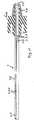
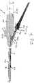
1 Eine erfindungsgemäße Sensoreinheit in gestrecktem Zustand;2 die erfindungsgemäße Sensoreinheit der1 im abgewickelten Zustand;3 ein Blockschaltbild des erfindungsgemäßen Navigationssystems;4 ein Ablaufdiagramm des erfindungsgemäßen Verfahrens;5 die mittels des erfindungsgemäßen Navigationssystems aufgrund der Ausrichtung der Sensoreinheit automatisch erzeugte Darstellung von chirurgischem Instrument in Überlagerung mit der Darstellung von Wirbelsäulenbereichen eines Patienten bei einer Hohlnadel;6 die mittels des erfindungsgemäßen Navigationssystems aufgrund der Ausrichtung der Sensoreinheit automatisch erzeugte Darstellung von chirurgischem Instrument in Überlagerung mit der Darstellung von Wirbelsäulenbereichen eines Patienten bei einem Endoskop; und7 die Anordnung einer erfindungsgemäßen Sensoreinheit in einem Endoskop zur Bildung einer Endoskopvorrichtung.
1 A sensor unit according to the invention in the stretched state;2 the sensor unit of theinvention 1 in the unwound state;3 a block diagram of the navigation system according to the invention;4 a flow diagram of the method according to the invention;5 the automatically generated by means of the navigation system according to the invention due to the orientation of the sensor unit representation of surgical instrument in superposition with the representation of spinal areas of a patient in a hollow needle;6 the automatically generated by the navigation system according to the invention due to the orientation of the sensor unit representation of surgical instrument in superposition with the representation of spinal areas of a patient in an endoscope; and7 the arrangement of a sensor unit according to the invention in an endoscope for forming an endoscope device.
Die
Unmittelbar proximal des Luer-Adapterteils
Schutzschlauch
Werden die Spulen
Da es bei einer Hohlnadel, deren distales Ende sich am Operationsort befindet, auf die Kenntnis des Orts des distalen Endes der Hohlnadel (und damit auch eines separaten eingeführten Arbeitsinstruments) im Raum sowie die Ausrichtung der Hohlnadel (und des Arbeitsinstruments, nicht aber der Drehung der Hohlnadel und des Arbeitsinstruments um ihre Achse) ankommt, reicht ein solcher 5-DOF-Sensor für die Bestimmung von Ausrichtung des distalen Endes der Hohlnadel und des Arbeitswerkzeugs aus und kann durch einen Sensor, der bis zum distalen Ende der Hohlnadel eingeführt ist, im inhomogenen Feld bestimmt werden.Since it is in a hollow needle whose distal end is located at the surgical site on the knowledge of the location of the distal end of the hollow needle (and thus a separate imported working instrument) in space and the alignment of the hollow needle (and the working instrument, but not the rotation of Hollow needle and the working instrument around its axis) arrives, such a 5-DOF sensor sufficient for the determination of alignment of the distal end of the hollow needle and the working tool and can by a sensor which is inserted to the distal end of the hollow needle in the inhomogeneous Field to be determined.
Gemäß
Die Kombination der beiden Spulen
Die
Die Steuer- und Verarbeitungselektronik
Die Navigationseinheit
Das Funktionsmodul
Die Verarbeitungseinheit
Das Videosignal des Endoskops
Der Arbeitsablauf des erfindungsgemäßen Navigationssystems ist entsprechend der
Nach Starten Navigationseinheit
Wird in Schritt
Erkennt das Navigationssystem aufgrund der axialen Ausrichtung der beiden Spulen
Im Monitorbild
Erkennt das Navigationssystem
Das erfindungsgemäße Navigationssystem erkennt aufgrund der Ausrichtung der beiden Spulen der Sensoreinheit zueinander unmittelbar die Art des Operationsgegenstandes, dessen distales Ende sich am Operationsort befindet und dem Operateur wird automatisch die entsprechende für ihn relevante Darstellung auf dem Monitor
Der Einsatz der erfindungsgemäßen Sensoreinheit bei einem Endoskop ist in der
Die dortige Endoskop-Vorrichtung
Durch das Lumen
Die Spule
Bei einem extern angelegten inhomogenen elektromagnetischen Feld - wie durch den Felderzeuger
Die Sensoreinheit
Damit erkennt ein Operateur aufgrund der Auswertung der Sensorsignale und einer Bildanzeige auf einem Bildschirm der Auswerteeinrichtung genau die Position des distalen Endes
Claims (17)
Translated fromGermanPriority Applications (20)
| Application Number | Priority Date | Filing Date | Title |
|---|---|---|---|
| DE102017008148.4ADE102017008148A1 (en) | 2017-08-29 | 2017-08-29 | Sensor unit, intraoperative navigation system and method for detecting a surgical instrument |
| DE202017004822.1UDE202017004822U1 (en) | 2017-08-29 | 2017-09-15 | Endoscope apparatus |
| JP2019567272AJP7329248B2 (en) | 2017-08-29 | 2018-08-20 | endoscope device |
| PL18765356TPL3641621T3 (en) | 2017-08-29 | 2018-08-20 | Endoscope device |
| US16/636,540US11647891B2 (en) | 2017-08-29 | 2018-08-20 | Endoscope device |
| EP18765356.3AEP3641621B1 (en) | 2017-08-29 | 2018-08-20 | Endoscope device |
| PCT/EP2018/000405WO2019042578A1 (en) | 2017-08-29 | 2018-08-20 | ENDOSCOPE DEVICE |
| ES18765356TES2888423T3 (en) | 2017-08-29 | 2018-08-20 | endoscope device |
| KR1020207005057AKR102612012B1 (en) | 2017-08-29 | 2018-08-20 | endoscope device |
| CN201880054041.5ACN111031885B (en) | 2017-08-29 | 2018-08-20 | Endoscope apparatus |
| CA3071473ACA3071473C (en) | 2017-08-29 | 2018-08-20 | Endoscope device |
| ES18769945TES2968463T3 (en) | 2017-08-29 | 2018-08-24 | Detection system for automatic detection of surgical instruments |
| CN201880054048.7ACN111031886B (en) | 2017-08-29 | 2018-08-24 | Detection system and method for automatically detecting surgical instruments |
| KR1020207005058AKR102577934B1 (en) | 2017-08-29 | 2018-08-24 | Detection system and method for automatic detection of surgical instruments |
| EP18769945.9AEP3500152B1 (en) | 2017-08-29 | 2018-08-24 | Detection system for automatically detecting surgical instruments |
| PCT/EP2018/000413WO2019042579A1 (en) | 2017-08-29 | 2018-08-24 | DETECTION SYSTEM AND METHOD FOR THE AUTOMATIC DETECTION OF SURGICAL INSTRUMENTS |
| CA3071475ACA3071475A1 (en) | 2017-08-29 | 2018-08-24 | Detection system and method for automatic detection of surgical instruments |
| US16/636,580US11730342B2 (en) | 2017-08-29 | 2018-08-24 | Detection system and method for automatic detection of surgical instruments |
| JP2019566876AJP7367976B2 (en) | 2017-08-29 | 2018-08-24 | Detection system and method for automatic detection of surgical instruments |
| US18/341,899US20230355078A1 (en) | 2017-08-29 | 2023-06-27 | Detection system and method for automatic detection of surgical instruments |
Applications Claiming Priority (1)
| Application Number | Priority Date | Filing Date | Title |
|---|---|---|---|
| DE102017008148.4ADE102017008148A1 (en) | 2017-08-29 | 2017-08-29 | Sensor unit, intraoperative navigation system and method for detecting a surgical instrument |
Publications (1)
| Publication Number | Publication Date |
|---|---|
| DE102017008148A1true DE102017008148A1 (en) | 2019-02-28 |
Family
ID=60419549
Family Applications (2)
| Application Number | Title | Priority Date | Filing Date |
|---|---|---|---|
| DE102017008148.4AWithdrawnDE102017008148A1 (en) | 2017-08-29 | 2017-08-29 | Sensor unit, intraoperative navigation system and method for detecting a surgical instrument |
| DE202017004822.1UActiveDE202017004822U1 (en) | 2017-08-29 | 2017-09-15 | Endoscope apparatus |
Family Applications After (1)
| Application Number | Title | Priority Date | Filing Date |
|---|---|---|---|
| DE202017004822.1UActiveDE202017004822U1 (en) | 2017-08-29 | 2017-09-15 | Endoscope apparatus |
Country Status (10)
| Country | Link |
|---|---|
| US (3) | US11647891B2 (en) |
| EP (2) | EP3641621B1 (en) |
| JP (2) | JP7329248B2 (en) |
| KR (2) | KR102612012B1 (en) |
| CN (2) | CN111031885B (en) |
| CA (2) | CA3071473C (en) |
| DE (2) | DE102017008148A1 (en) |
| ES (2) | ES2888423T3 (en) |
| PL (1) | PL3641621T3 (en) |
| WO (2) | WO2019042578A1 (en) |
Families Citing this family (11)
| Publication number | Priority date | Publication date | Assignee | Title |
|---|---|---|---|---|
| DE102017008148A1 (en)* | 2017-08-29 | 2019-02-28 | Joimax Gmbh | Sensor unit, intraoperative navigation system and method for detecting a surgical instrument |
| WO2020014207A1 (en)* | 2018-07-10 | 2020-01-16 | Intuitive Surgical Operations, Inc. | Systems for sensing presence of medical tools |
| WO2020221940A1 (en)* | 2019-05-02 | 2020-11-05 | Fiagon Ag Medical Technologies | Surgical kit for minimally invasive spine surgery |
| SG11202110918UA (en)* | 2019-05-02 | 2021-10-28 | Intersect Ent Int Gmbh | Sensor carrier |
| DE102019003965A1 (en) | 2019-06-05 | 2020-12-10 | Joimax Gmbh | Surgical needle set and method for determining the position of a surgical instrument |
| EA202192999A1 (en) | 2019-10-15 | 2022-03-25 | ИНТЕРСЕКТ ИЭнТи ИНТЕРНЭШНЛ ГМБХ | SURGICAL KIT FOR MINIMALLY INVASIVE SPINE SURGERY |
| CN112402038B (en)* | 2020-11-20 | 2022-09-13 | 山东威高医疗科技有限公司 | Automatic identification method of instrument used in cooperation with electromagnetic navigation system |
| US20220257093A1 (en)* | 2021-02-18 | 2022-08-18 | Acclarent, Inc. | Flexible sensor assembly for ent instrument |
| US12290319B2 (en) | 2021-09-29 | 2025-05-06 | Cilag Gmbh International | Methods for controlling cooperative surgical instruments |
| US12229953B2 (en)* | 2021-11-24 | 2025-02-18 | GE Precision Healthcare LLC | System and method for visualizing placement of a medical tube or line |
| CN116327102A (en)* | 2023-04-12 | 2023-06-27 | 上海卓昕医疗科技有限公司 | Electronic bronchus endoscope capable of positioning and navigation and insertion tube thereof |
Citations (2)
| Publication number | Priority date | Publication date | Assignee | Title |
|---|---|---|---|---|
| US20040097805A1 (en)* | 2002-11-19 | 2004-05-20 | Laurent Verard | Navigation system for cardiac therapies |
| US20070164900A1 (en)* | 2005-12-30 | 2007-07-19 | Schneider Mark D | Therapy delivery system including a navigation element |
Family Cites Families (89)
| Publication number | Priority date | Publication date | Assignee | Title |
|---|---|---|---|---|
| US4911148A (en)* | 1989-03-14 | 1990-03-27 | Intramed Laboratories, Inc. | Deflectable-end endoscope with detachable flexible shaft assembly |
| US5211165A (en)* | 1991-09-03 | 1993-05-18 | General Electric Company | Tracking system to follow the position and orientation of a device with radiofrequency field gradients |
| US5318025A (en)* | 1992-04-01 | 1994-06-07 | General Electric Company | Tracking system to monitor the position and orientation of a device using multiplexed magnetic resonance detection |
| US5325873A (en)* | 1992-07-23 | 1994-07-05 | Abbott Laboratories | Tube placement verifier system |
| JP3506770B2 (en)* | 1994-04-21 | 2004-03-15 | オリンパス株式会社 | Endoscope position detection device |
| US6059718A (en)* | 1993-10-18 | 2000-05-09 | Olympus Optical Co., Ltd. | Endoscope form detecting apparatus in which coil is fixedly mounted by insulating member so that form is not deformed within endoscope |
| SE9304261D0 (en)* | 1993-12-22 | 1993-12-22 | Radi Medical Systems | Biopsy sampling device |
| JP4159396B2 (en)* | 1994-08-18 | 2008-10-01 | オリンパス株式会社 | Endoscope shape detection device |
| AU1693095A (en)* | 1994-08-19 | 1996-03-14 | Biosense, Inc. | Medical diagnosis, treatment and imaging systems |
| US5735793A (en)* | 1995-01-12 | 1998-04-07 | Olympus Optical Co., Ltd. | Endoscope |
| US5592939A (en)* | 1995-06-14 | 1997-01-14 | Martinelli; Michael A. | Method and system for navigating a catheter probe |
| AT1103U1 (en)* | 1995-10-11 | 1996-10-25 | Avl Verbrennungskraft Messtech | OPTOELECTRICAL MEASURING DEVICE FOR DETECTING COMBUSTION IN THE COMBUSTION CHAMBER |
| JP3748985B2 (en)* | 1997-05-29 | 2006-02-22 | オリンパス株式会社 | Coil position measuring device, endoscope insertion shape detecting device, and coil position measuring method |
| US5997473A (en) | 1996-09-06 | 1999-12-07 | Olympus Optical Co., Ltd. | Method of locating a coil which consists of determining the space occupied by a source coil generating a magnetic field |
| SI0901341T1 (en)* | 1997-01-03 | 2005-04-30 | Biosense Webster, Inc. | Bend-responsive catheter |
| US5928248A (en)* | 1997-02-14 | 1999-07-27 | Biosense, Inc. | Guided deployment of stents |
| US6511417B1 (en)* | 1998-09-03 | 2003-01-28 | Olympus Optical Co., Ltd. | System for detecting the shape of an endoscope using source coils and sense coils |
| JP3290153B2 (en)* | 1998-12-17 | 2002-06-10 | オリンパス光学工業株式会社 | Endoscope insertion shape detection device |
| US7809421B1 (en)* | 2000-07-20 | 2010-10-05 | Biosense, Inc. | Medical system calibration with static metal compensation |
| US20040087877A1 (en)* | 2000-08-23 | 2004-05-06 | Besz William John | Catheter locator apparatus and method of use |
| JP2003180697A (en)* | 2001-12-18 | 2003-07-02 | Olympus Optical Co Ltd | Ultrasonic diagnostic equipment |
| US8211010B2 (en)* | 2002-10-29 | 2012-07-03 | Olympus Corporation | Endoscope information processor and processing method |
| US6887194B2 (en)* | 2003-01-17 | 2005-05-03 | Applied Medical Resources Corporation | Surgical access apparatus and method |
| US7660623B2 (en)* | 2003-01-30 | 2010-02-09 | Medtronic Navigation, Inc. | Six degree of freedom alignment display for medical procedures |
| EP1797812B1 (en)* | 2003-08-22 | 2011-04-13 | Olympus Corporation | Device for detecting shape of endoscope |
| US7901348B2 (en)* | 2003-12-12 | 2011-03-08 | University Of Washington | Catheterscope 3D guidance and interface system |
| JP4481711B2 (en)* | 2004-04-09 | 2010-06-16 | オリンパス株式会社 | Insertion shape detection probe |
| JP4578942B2 (en)* | 2004-11-10 | 2010-11-10 | オリンパス株式会社 | Endoscope shape detection device |
| AU2005303012B2 (en)* | 2004-11-15 | 2009-01-08 | Olympus Corporation | Endoscope profile detector |
| JP4749703B2 (en)* | 2004-12-01 | 2011-08-17 | オリンパス株式会社 | Endoscope insertion shape detection device |
| US8571635B2 (en) | 2005-04-28 | 2013-10-29 | Boston Scientific Scimed, Inc. | Automated activation/deactivation of imaging device based on tracked medical device position |
| CN1695555A (en)* | 2005-05-27 | 2005-11-16 | 四川大学华西医院 | Closed type artery indwelling needle |
| US20070106114A1 (en) | 2005-11-09 | 2007-05-10 | Pentax Corporation | Endoscope-shape monitoring system |
| JP2007130132A (en) | 2005-11-09 | 2007-05-31 | Pentax Corp | Endoscope insertion part shape grasping system |
| US8016749B2 (en) | 2006-03-21 | 2011-09-13 | Boston Scientific Scimed, Inc. | Vision catheter having electromechanical navigation |
| JP4153963B2 (en)* | 2006-06-12 | 2008-09-24 | オリンパスメディカルシステムズ株式会社 | Endoscope insertion shape detection device |
| DE102006029122A1 (en)* | 2006-06-22 | 2007-12-27 | Amedo Gmbh | System for determining the position of a medical instrument |
| US8197494B2 (en)* | 2006-09-08 | 2012-06-12 | Corpak Medsystems, Inc. | Medical device position guidance system with wireless connectivity between a noninvasive device and an invasive device |
| US7892165B2 (en) | 2006-10-23 | 2011-02-22 | Hoya Corporation | Camera calibration for endoscope navigation system |
| AU2013251245B2 (en) | 2006-12-08 | 2015-05-14 | Biosense Webster, Inc. | Coloring electroanatomical maps to indicate ultrasound data acquisition |
| US20080172119A1 (en)* | 2007-01-12 | 2008-07-17 | Medtronic Vascular, Inc. | Prosthesis Deployment Apparatus and Methods |
| WO2009044580A1 (en)* | 2007-10-02 | 2009-04-09 | Olympus Medical Systems Corp. | Endoscope-shaped analyzer |
| ES2465915T3 (en)* | 2007-11-26 | 2014-06-09 | C.R. Bard, Inc. | Integrated system for intravascular catheter placement |
| EP2213220B9 (en)* | 2007-11-29 | 2013-08-21 | Olympus Medical Systems Corp. | Endoscope system |
| US20100030063A1 (en)* | 2008-07-31 | 2010-02-04 | Medtronic, Inc. | System and method for tracking an instrument |
| US8926528B2 (en)* | 2008-08-06 | 2015-01-06 | Biosense Webster, Inc. | Single-axis sensors on flexible backbone |
| US8611984B2 (en)* | 2009-04-08 | 2013-12-17 | Covidien Lp | Locatable catheter |
| US8706193B2 (en)* | 2009-06-22 | 2014-04-22 | Biosense Webster, Inc. | Catheter with obliquely-oriented coils |
| US9179827B2 (en)* | 2009-12-15 | 2015-11-10 | Boston Scientific Scimed, Inc. | Systems and methods for determining the position and orientation of medical devices inserted into a patient |
| US10966701B2 (en)* | 2009-12-16 | 2021-04-06 | Boston Scientific Scimed, Inc. | Tissue retractor for minimally invasive surgery |
| US8870898B2 (en)* | 2010-01-05 | 2014-10-28 | GI Windows, Inc. | Self-assembling magnetic anastomosis device having an exoskeleton |
| EP4122385A1 (en)* | 2010-05-28 | 2023-01-25 | C. R. Bard, Inc. | Insertion guidance system for needles and medical components |
| EP2912999B1 (en)* | 2010-05-28 | 2022-06-29 | C. R. Bard, Inc. | Apparatus for use with needle insertion guidance system |
| KR101598773B1 (en)* | 2010-10-21 | 2016-03-15 | (주)미래컴퍼니 | Method and device for controlling/compensating movement of surgical robot |
| WO2012095845A1 (en)* | 2011-01-14 | 2012-07-19 | Technion Research & Development Foundation Ltd. | Robot for minimally invasive neurosurgery |
| WO2012103169A2 (en)* | 2011-01-25 | 2012-08-02 | Smith & Nephew, Inc. | Targeting operation sites |
| JP2012170628A (en)* | 2011-02-22 | 2012-09-10 | Fujifilm Corp | Endoscope, and endoscope assembling method |
| DE102011017719A1 (en)* | 2011-04-28 | 2012-10-31 | Siemens Aktiengesellschaft | Arrangement for navigating endoscopic capsule, has sensor coil pair provided outside of endoscopic capsule for determining position or orientation of capsule, where sensor coil pair is comprised of two sensor coils |
| JP5319859B1 (en)* | 2011-09-15 | 2013-10-16 | オリンパスメディカルシステムズ株式会社 | Probe for endoscope insertion shape observation |
| US20130303944A1 (en) | 2012-05-14 | 2013-11-14 | Intuitive Surgical Operations, Inc. | Off-axis electromagnetic sensor |
| JP6430831B2 (en) | 2011-10-14 | 2018-11-28 | インテュイティブ サージカル オペレーションズ, インコーポレイテッド | Catheter system |
| JP5973727B2 (en)* | 2011-12-28 | 2016-08-23 | オリンパス株式会社 | Stereoscopic endoscope apparatus, stereoscopic endoscope system, and stereoscopic endoscope robot |
| JP2013165892A (en)* | 2012-02-16 | 2013-08-29 | Hoya Corp | Magnifying endoscope |
| US9510772B2 (en)* | 2012-04-10 | 2016-12-06 | Cardionxt, Inc. | System and method for localizing medical instruments during cardiovascular medical procedures |
| DE102012008970B3 (en)* | 2012-05-03 | 2013-06-27 | Joimax Gmbh | Surgical tooling |
| EP2850992A4 (en)* | 2012-05-14 | 2016-02-17 | Olympus Corp | Capsule therapy device and therapy system |
| US9463307B2 (en)* | 2012-12-21 | 2016-10-11 | Medtronic Xomed, Inc. | Sinus dilation system and method |
| DE102013004964B4 (en)* | 2013-03-22 | 2016-11-03 | Joimax Gmbh | Instrument set and method for inserting a basket into the disc space between two vertebral bodies |
| EP3102087A4 (en)* | 2014-02-05 | 2017-10-25 | National University of Singapore | Systems and methods for tracking and displaying endoscope shape and distal end orientation |
| KR102536576B1 (en)* | 2014-03-17 | 2023-05-26 | 인튜어티브 서지컬 오퍼레이션즈 인코포레이티드 | Surgical cannulas and related systems and methods of identifying surgical cannulas |
| JP5830576B1 (en)* | 2014-06-04 | 2015-12-09 | 日立アロカメディカル株式会社 | Medical system |
| EP3056145B1 (en)* | 2014-12-18 | 2023-12-06 | Karl Storz SE & Co. KG | Method for determining a position and an orientation of an endoscope within a cavity |
| JP2018515221A (en)* | 2015-05-08 | 2018-06-14 | ジーアイ ウィンドウズ, インコーポレイテッド | System, device, and method for forming an anastomosis |
| US10426555B2 (en)* | 2015-06-03 | 2019-10-01 | Covidien Lp | Medical instrument with sensor for use in a system and method for electromagnetic navigation |
| US11065063B2 (en)* | 2015-07-02 | 2021-07-20 | Board Of Regents, The University Of Texas System | Utilization of laser interstitial thermotherapy guided with real time thermal MRI |
| EP3331429B1 (en)* | 2015-07-06 | 2020-09-02 | Metritrack, Inc. | Sensor assembly for use with a positional tracking system and method of manufacture |
| JP6824967B2 (en)* | 2015-09-18 | 2021-02-03 | オーリス ヘルス インコーポレイテッド | Tubular net navigation |
| CN108289689A (en)* | 2015-10-13 | 2018-07-17 | 普罗维登斯医疗技术公司 | Joint of vertebral column implantation material conveying device and system |
| JP7210279B2 (en)* | 2015-10-21 | 2023-01-23 | コーニンクレッカ フィリップス エヌ ヴェ | A system that supports targeted treatment |
| US10932691B2 (en)* | 2016-01-26 | 2021-03-02 | Auris Health, Inc. | Surgical tools having electromagnetic tracking components |
| US11000207B2 (en)* | 2016-01-29 | 2021-05-11 | C. R. Bard, Inc. | Multiple coil system for tracking a medical device |
| US10478254B2 (en)* | 2016-05-16 | 2019-11-19 | Covidien Lp | System and method to access lung tissue |
| US11058446B2 (en)* | 2016-09-14 | 2021-07-13 | Biosense Webster (Israel) Ltd. | ENT tool antenna |
| KR102576296B1 (en)* | 2017-05-17 | 2023-09-08 | 아우리스 헬스, 인코포레이티드 | Interchangeable working channels |
| DE102017008148A1 (en)* | 2017-08-29 | 2019-02-28 | Joimax Gmbh | Sensor unit, intraoperative navigation system and method for detecting a surgical instrument |
| US11672412B2 (en)* | 2017-10-13 | 2023-06-13 | Intuitive Surgical Operations, Inc. | Systems and methods for detecting environmental forces on an elongate device |
| US20190167151A1 (en)* | 2017-12-05 | 2019-06-06 | Acclarent, Inc. | System and method for tracking patient movement during guided medical procedure |
| DE102019003965A1 (en)* | 2019-06-05 | 2020-12-10 | Joimax Gmbh | Surgical needle set and method for determining the position of a surgical instrument |
| EP3909537B1 (en)* | 2020-05-14 | 2022-11-30 | Stryker European Operations Limited | Tracking device, surgical instrument comprising same, and surgical navigation system with the surgical instrument |
- 2017
- 2017-08-29DEDE102017008148.4Apatent/DE102017008148A1/ennot_activeWithdrawn
- 2017-09-15DEDE202017004822.1Upatent/DE202017004822U1/enactiveActive
- 2018
- 2018-08-20CNCN201880054041.5Apatent/CN111031885B/enactiveActive
- 2018-08-20WOPCT/EP2018/000405patent/WO2019042578A1/ennot_activeCeased
- 2018-08-20PLPL18765356Tpatent/PL3641621T3/enunknown
- 2018-08-20EPEP18765356.3Apatent/EP3641621B1/enactiveActive
- 2018-08-20CACA3071473Apatent/CA3071473C/enactiveActive
- 2018-08-20USUS16/636,540patent/US11647891B2/enactiveActive
- 2018-08-20ESES18765356Tpatent/ES2888423T3/enactiveActive
- 2018-08-20KRKR1020207005057Apatent/KR102612012B1/enactiveActive
- 2018-08-20JPJP2019567272Apatent/JP7329248B2/enactiveActive
- 2018-08-24USUS16/636,580patent/US11730342B2/enactiveActive
- 2018-08-24EPEP18769945.9Apatent/EP3500152B1/enactiveActive
- 2018-08-24WOPCT/EP2018/000413patent/WO2019042579A1/ennot_activeCeased
- 2018-08-24JPJP2019566876Apatent/JP7367976B2/enactiveActive
- 2018-08-24KRKR1020207005058Apatent/KR102577934B1/enactiveActive
- 2018-08-24CACA3071475Apatent/CA3071475A1/enactivePending
- 2018-08-24ESES18769945Tpatent/ES2968463T3/enactiveActive
- 2018-08-24CNCN201880054048.7Apatent/CN111031886B/enactiveActive
- 2023
- 2023-06-27USUS18/341,899patent/US20230355078A1/ennot_activeAbandoned
Patent Citations (2)
| Publication number | Priority date | Publication date | Assignee | Title |
|---|---|---|---|---|
| US20040097805A1 (en)* | 2002-11-19 | 2004-05-20 | Laurent Verard | Navigation system for cardiac therapies |
| US20070164900A1 (en)* | 2005-12-30 | 2007-07-19 | Schneider Mark D | Therapy delivery system including a navigation element |
Also Published As
| Publication number | Publication date |
|---|---|
| US20230355078A1 (en) | 2023-11-09 |
| JP2020532331A (en) | 2020-11-12 |
| CA3071473A1 (en) | 2019-03-07 |
| PL3641621T3 (en) | 2022-01-03 |
| US11730342B2 (en) | 2023-08-22 |
| KR102577934B1 (en) | 2023-09-14 |
| ES2888423T3 (en) | 2022-01-04 |
| WO2019042578A1 (en) | 2019-03-07 |
| EP3500152B1 (en) | 2023-10-18 |
| CN111031886B (en) | 2024-04-26 |
| US11647891B2 (en) | 2023-05-16 |
| JP7367976B2 (en) | 2023-10-24 |
| EP3641621B1 (en) | 2021-07-14 |
| EP3641621A1 (en) | 2020-04-29 |
| CA3071475A1 (en) | 2019-03-07 |
| DE202017004822U1 (en) | 2017-11-07 |
| KR20200047537A (en) | 2020-05-07 |
| EP3500152A1 (en) | 2019-06-26 |
| JP2020532332A (en) | 2020-11-12 |
| US20210177245A1 (en) | 2021-06-17 |
| CN111031885B (en) | 2023-09-12 |
| KR20200047536A (en) | 2020-05-07 |
| ES2968463T3 (en) | 2024-05-09 |
| CA3071473C (en) | 2024-04-09 |
| CN111031886A (en) | 2020-04-17 |
| JP7329248B2 (en) | 2023-08-18 |
| US20210153724A1 (en) | 2021-05-27 |
| KR102612012B1 (en) | 2023-12-11 |
| CN111031885A (en) | 2020-04-17 |
| WO2019042579A1 (en) | 2019-03-07 |
Similar Documents
| Publication | Publication Date | Title |
|---|---|---|
| DE102017008148A1 (en) | Sensor unit, intraoperative navigation system and method for detecting a surgical instrument | |
| DE69922980T2 (en) | METHOD AND DEVICE FOR POSITIONING A DEVICE IN A BODY | |
| DE10202091B4 (en) | Device for determining a coordinate transformation | |
| DE10210287B4 (en) | Method and device for markerless registration for navigation-guided interventions | |
| DE69322202T2 (en) | System and method for improving endoscopic surgery | |
| DE19843408C2 (en) | Method for reproducing x-ray images when positioning a catheter inserted into a vessel and device for carrying out the method | |
| DE202011110755U1 (en) | Navigation attachment for optical devices in medicine and device for displaying image data | |
| EP4213755B1 (en) | Surgical assistance system | |
| DE10323008A1 (en) | Automatic fusion of 2D fluoroscopic C-frame X-ray images with preoperative 3D images using navigation markers, by use of a projection matrix based on a 2D fluoroscopy image and a defined reference navigation system | |
| DE10240727A1 (en) | Imaging system and method for optimizing an x-ray image | |
| DE102006001884A1 (en) | Medical instrument`s e.g. intracranial catheter, guidance visual aiding method, involves marking input point and/or target point in spatial representation of hollow organ section of examination object by medical personnel | |
| DE102012220116A1 (en) | Mobile device, in particular for processing or observation of a body, and method for handling, in particular calibration, of a device | |
| DE102010029275A1 (en) | Method for moving an instrument arm of a Laparoskopierobotors in a predetermined relative position to a trocar | |
| DE102004024097A1 (en) | Method and apparatus for increasing patient safety in clinical scanners | |
| DE102005059804A1 (en) | Navigation of inserted medical instrument in a patient, e.g. a catheter, uses initial three dimensional image of the target zone to give a number of two-dimensional images for comparison with fluoroscopic images taken during the operation | |
| DE102004044285A1 (en) | System and method for determining the position of an elastic instrument used in a position tracking system | |
| WO2008058520A2 (en) | Apparatus for supplying images to an operator | |
| DE102008055918A1 (en) | Method for operating a medical navigation system and medical navigation system | |
| DE102005041602A1 (en) | Method for displaying a medical implant in an image and medical imaging system | |
| DE112021003530T5 (en) | System for assisting a user in placing a penetrating device in tissue | |
| DE102004015858A1 (en) | Imaging medical examination device | |
| EP3979929A1 (en) | Surgical needle set and method for determining the position of a surgical instrument | |
| DE10160530A1 (en) | Magnetic resonance imaging method, especially for MR angiography where the image of a blood vessel is obtained for insertion of e.g. a catheter, by obtaining multiple sectional images of the vessel at different angles | |
| EP4228543A1 (en) | Surgical navigation system having improved instrument tracking and navigation method | |
| DE102022125798A1 (en) | Procedure for medical technical calibration |
Legal Events
| Date | Code | Title | Description |
|---|---|---|---|
| R163 | Identified publications notified | ||
| R005 | Application deemed withdrawn due to failure to request examination |