DE102017005797A1 - Filter system with filter element and secondary element - Google Patents
Filter system with filter element and secondary elementDownload PDFInfo
- Publication number
- DE102017005797A1 DE102017005797A1DE102017005797.4ADE102017005797ADE102017005797A1DE 102017005797 A1DE102017005797 A1DE 102017005797A1DE 102017005797 ADE102017005797 ADE 102017005797ADE 102017005797 A1DE102017005797 A1DE 102017005797A1
- Authority
- DE
- Germany
- Prior art keywords
- filter
- housing
- central tube
- secondary element
- filter system
- Prior art date
- Legal status (The legal status is an assumption and is not a legal conclusion. Google has not performed a legal analysis and makes no representation as to the accuracy of the status listed.)
- Ceased
Links
- 239000012530fluidSubstances0.000claimsabstractdescription60
- 230000004323axial lengthEffects0.000claimsabstractdescription14
- 238000001914filtrationMethods0.000claimsabstractdescription5
- 238000007789sealingMethods0.000claimsdescription18
- 238000000034methodMethods0.000claimsdescription7
- 238000007599dischargingMethods0.000claimsdescription2
- 239000002245particleSubstances0.000description5
- 238000004519manufacturing processMethods0.000description3
- 238000002485combustion reactionMethods0.000description2
- 238000009434installationMethods0.000description2
- 239000000463materialSubstances0.000description2
- 239000002984plastic foamSubstances0.000description2
- BUHVIAUBTBOHAG-FOYDDCNASA-N(2r,3r,4s,5r)-2-[6-[[2-(3,5-dimethoxyphenyl)-2-(2-methylphenyl)ethyl]amino]purin-9-yl]-5-(hydroxymethyl)oxolane-3,4-diolChemical compoundCOC1=CC(OC)=CC(C(CNC=2C=3N=CN(C=3N=CN=2)[C@H]2[C@@H]([C@H](O)[C@@H](CO)O2)O)C=2C(=CC=CC=2)C)=C1BUHVIAUBTBOHAG-FOYDDCNASA-N0.000description1
- 230000003247decreasing effectEffects0.000description1
- 238000006073displacement reactionMethods0.000description1
- 230000000694effectsEffects0.000description1
- 230000002349favourable effectEffects0.000description1
- 229920002635polyurethanePolymers0.000description1
- 239000004814polyurethaneSubstances0.000description1
- 230000035939shockEffects0.000description1
Images


Classifications
- B—PERFORMING OPERATIONS; TRANSPORTING
- B01—PHYSICAL OR CHEMICAL PROCESSES OR APPARATUS IN GENERAL
- B01D—SEPARATION
- B01D35/00—Filtering devices having features not specifically covered by groups B01D24/00 - B01D33/00, or for applications not specifically covered by groups B01D24/00 - B01D33/00; Auxiliary devices for filtration; Filter housing constructions
- B01D35/30—Filter housing constructions
- B—PERFORMING OPERATIONS; TRANSPORTING
- B01—PHYSICAL OR CHEMICAL PROCESSES OR APPARATUS IN GENERAL
- B01D—SEPARATION
- B01D29/00—Filters with filtering elements stationary during filtration, e.g. pressure or suction filters, not covered by groups B01D24/00 - B01D27/00; Filtering elements therefor
- B01D29/96—Filters with filtering elements stationary during filtration, e.g. pressure or suction filters, not covered by groups B01D24/00 - B01D27/00; Filtering elements therefor in which the filtering elements are moved between filtering operations; Particular measures for removing or replacing the filtering elements; Transport systems for filters
- B—PERFORMING OPERATIONS; TRANSPORTING
- B01—PHYSICAL OR CHEMICAL PROCESSES OR APPARATUS IN GENERAL
- B01D—SEPARATION
- B01D27/00—Cartridge filters of the throw-away type
- B01D27/08—Construction of the casing
- B—PERFORMING OPERATIONS; TRANSPORTING
- B01—PHYSICAL OR CHEMICAL PROCESSES OR APPARATUS IN GENERAL
- B01D—SEPARATION
- B01D29/00—Filters with filtering elements stationary during filtration, e.g. pressure or suction filters, not covered by groups B01D24/00 - B01D27/00; Filtering elements therefor
- B01D29/0097—Curved filtering elements, e.g. concave filtering elements
- B—PERFORMING OPERATIONS; TRANSPORTING
- B01—PHYSICAL OR CHEMICAL PROCESSES OR APPARATUS IN GENERAL
- B01D—SEPARATION
- B01D46/00—Filters or filtering processes specially modified for separating dispersed particles from gases or vapours
- B01D46/0002—Casings; Housings; Frame constructions
- B01D46/0005—Mounting of filtering elements within casings, housings or frames
- B—PERFORMING OPERATIONS; TRANSPORTING
- B01—PHYSICAL OR CHEMICAL PROCESSES OR APPARATUS IN GENERAL
- B01D—SEPARATION
- B01D46/00—Filters or filtering processes specially modified for separating dispersed particles from gases or vapours
- B01D46/0039—Filters or filtering processes specially modified for separating dispersed particles from gases or vapours with flow guiding by feed or discharge devices
- B01D46/0041—Filters or filtering processes specially modified for separating dispersed particles from gases or vapours with flow guiding by feed or discharge devices for feeding
- B—PERFORMING OPERATIONS; TRANSPORTING
- B01—PHYSICAL OR CHEMICAL PROCESSES OR APPARATUS IN GENERAL
- B01D—SEPARATION
- B01D46/00—Filters or filtering processes specially modified for separating dispersed particles from gases or vapours
- B01D46/0084—Filters or filtering processes specially modified for separating dispersed particles from gases or vapours provided with safety means
- B01D46/0097—Special means for preventing bypass around the filter, i.e. in addition to usual seals
- B—PERFORMING OPERATIONS; TRANSPORTING
- B01—PHYSICAL OR CHEMICAL PROCESSES OR APPARATUS IN GENERAL
- B01D—SEPARATION
- B01D46/00—Filters or filtering processes specially modified for separating dispersed particles from gases or vapours
- B01D46/24—Particle separators, e.g. dust precipitators, using rigid hollow filter bodies
- B01D46/2403—Particle separators, e.g. dust precipitators, using rigid hollow filter bodies characterised by the physical shape or structure of the filtering element
- B01D46/2411—Filter cartridges
- B—PERFORMING OPERATIONS; TRANSPORTING
- B01—PHYSICAL OR CHEMICAL PROCESSES OR APPARATUS IN GENERAL
- B01D—SEPARATION
- B01D46/00—Filters or filtering processes specially modified for separating dispersed particles from gases or vapours
- B01D46/52—Particle separators, e.g. dust precipitators, using filters embodying folded corrugated or wound sheet material
- B01D46/521—Particle separators, e.g. dust precipitators, using filters embodying folded corrugated or wound sheet material using folded, pleated material
- B—PERFORMING OPERATIONS; TRANSPORTING
- B01—PHYSICAL OR CHEMICAL PROCESSES OR APPARATUS IN GENERAL
- B01D—SEPARATION
- B01D46/00—Filters or filtering processes specially modified for separating dispersed particles from gases or vapours
- B01D46/56—Filters or filtering processes specially modified for separating dispersed particles from gases or vapours with multiple filtering elements, characterised by their mutual disposition
- B01D46/62—Filters or filtering processes specially modified for separating dispersed particles from gases or vapours with multiple filtering elements, characterised by their mutual disposition connected in series
- B01D46/64—Filters or filtering processes specially modified for separating dispersed particles from gases or vapours with multiple filtering elements, characterised by their mutual disposition connected in series arranged concentrically or coaxially
- F—MECHANICAL ENGINEERING; LIGHTING; HEATING; WEAPONS; BLASTING
- F02—COMBUSTION ENGINES; HOT-GAS OR COMBUSTION-PRODUCT ENGINE PLANTS
- F02M—SUPPLYING COMBUSTION ENGINES IN GENERAL WITH COMBUSTIBLE MIXTURES OR CONSTITUENTS THEREOF
- F02M35/00—Combustion-air cleaners, air intakes, intake silencers, or induction systems specially adapted for, or arranged on, internal-combustion engines
- F02M35/02—Air cleaners
- F02M35/024—Air cleaners using filters, e.g. moistened
- B—PERFORMING OPERATIONS; TRANSPORTING
- B01—PHYSICAL OR CHEMICAL PROCESSES OR APPARATUS IN GENERAL
- B01D—SEPARATION
- B01D2201/00—Details relating to filtering apparatus
- B01D2201/02—Filtering elements having a conical form
- B—PERFORMING OPERATIONS; TRANSPORTING
- B01—PHYSICAL OR CHEMICAL PROCESSES OR APPARATUS IN GENERAL
- B01D—SEPARATION
- B01D2201/00—Details relating to filtering apparatus
- B01D2201/04—Supports for the filtering elements
- B01D2201/0415—Details of supporting structures
- B—PERFORMING OPERATIONS; TRANSPORTING
- B01—PHYSICAL OR CHEMICAL PROCESSES OR APPARATUS IN GENERAL
- B01D—SEPARATION
- B01D2201/00—Details relating to filtering apparatus
- B01D2201/29—Filter cartridge constructions
- B01D2201/291—End caps
- B01D2201/295—End caps with projections extending in a radial outward direction, e.g. for use as a guide, spacing means
- B—PERFORMING OPERATIONS; TRANSPORTING
- B01—PHYSICAL OR CHEMICAL PROCESSES OR APPARATUS IN GENERAL
- B01D—SEPARATION
- B01D2201/00—Details relating to filtering apparatus
- B01D2201/34—Seals or gaskets for filtering elements
- B—PERFORMING OPERATIONS; TRANSPORTING
- B01—PHYSICAL OR CHEMICAL PROCESSES OR APPARATUS IN GENERAL
- B01D—SEPARATION
- B01D2265/00—Casings, housings or mounting for filters specially adapted for separating dispersed particles from gases or vapours
- B01D2265/06—Details of supporting structures for filtering material, e.g. cores
- B—PERFORMING OPERATIONS; TRANSPORTING
- B01—PHYSICAL OR CHEMICAL PROCESSES OR APPARATUS IN GENERAL
- B01D—SEPARATION
- B01D2271/00—Sealings for filters specially adapted for separating dispersed particles from gases or vapours
- B01D2271/02—Gaskets, sealings
- B01D2271/027—Radial sealings
- B—PERFORMING OPERATIONS; TRANSPORTING
- B01—PHYSICAL OR CHEMICAL PROCESSES OR APPARATUS IN GENERAL
- B01D—SEPARATION
- B01D2273/00—Operation of filters specially adapted for separating dispersed particles from gases or vapours
- B01D2273/10—Allowing a continuous bypass of at least part of the flow, e.g. of secondary air, vents
- B—PERFORMING OPERATIONS; TRANSPORTING
- B01—PHYSICAL OR CHEMICAL PROCESSES OR APPARATUS IN GENERAL
- B01D—SEPARATION
- B01D2279/00—Filters adapted for separating dispersed particles from gases or vapours specially modified for specific uses
- B01D2279/60—Filters adapted for separating dispersed particles from gases or vapours specially modified for specific uses for the intake of internal combustion engines or turbines
- B—PERFORMING OPERATIONS; TRANSPORTING
- B01—PHYSICAL OR CHEMICAL PROCESSES OR APPARATUS IN GENERAL
- B01D—SEPARATION
- B01D35/00—Filtering devices having features not specifically covered by groups B01D24/00 - B01D33/00, or for applications not specifically covered by groups B01D24/00 - B01D33/00; Auxiliary devices for filtration; Filter housing constructions
- B01D35/005—Filters specially adapted for use in internal-combustion engine lubrication or fuel systems
- F—MECHANICAL ENGINEERING; LIGHTING; HEATING; WEAPONS; BLASTING
- F02—COMBUSTION ENGINES; HOT-GAS OR COMBUSTION-PRODUCT ENGINE PLANTS
- F02M—SUPPLYING COMBUSTION ENGINES IN GENERAL WITH COMBUSTIBLE MIXTURES OR CONSTITUENTS THEREOF
- F02M35/00—Combustion-air cleaners, air intakes, intake silencers, or induction systems specially adapted for, or arranged on, internal-combustion engines
- F02M35/02—Air cleaners
- F02M35/024—Air cleaners using filters, e.g. moistened
- F02M35/02416—Fixing, mounting, supporting or arranging filter elements; Filter element cartridges
- F02M35/02433—Special alignment with respect to the air intake flow, e.g. angled or in longitudinal flow direction
- F—MECHANICAL ENGINEERING; LIGHTING; HEATING; WEAPONS; BLASTING
- F02—COMBUSTION ENGINES; HOT-GAS OR COMBUSTION-PRODUCT ENGINE PLANTS
- F02M—SUPPLYING COMBUSTION ENGINES IN GENERAL WITH COMBUSTIBLE MIXTURES OR CONSTITUENTS THEREOF
- F02M35/00—Combustion-air cleaners, air intakes, intake silencers, or induction systems specially adapted for, or arranged on, internal-combustion engines
- F02M35/02—Air cleaners
- F02M35/024—Air cleaners using filters, e.g. moistened
- F02M35/02441—Materials or structure of filter elements, e.g. foams
- F—MECHANICAL ENGINEERING; LIGHTING; HEATING; WEAPONS; BLASTING
- F02—COMBUSTION ENGINES; HOT-GAS OR COMBUSTION-PRODUCT ENGINE PLANTS
- F02M—SUPPLYING COMBUSTION ENGINES IN GENERAL WITH COMBUSTIBLE MIXTURES OR CONSTITUENTS THEREOF
- F02M35/00—Combustion-air cleaners, air intakes, intake silencers, or induction systems specially adapted for, or arranged on, internal-combustion engines
- F02M35/02—Air cleaners
- F02M35/024—Air cleaners using filters, e.g. moistened
- F02M35/02475—Air cleaners using filters, e.g. moistened characterised by the shape of the filter element
- F02M35/02483—Cylindrical, conical, oval, spherical or the like filter elements; wounded filter elements
Landscapes
- Chemical & Material Sciences (AREA)
- Chemical Kinetics & Catalysis (AREA)
- Engineering & Computer Science (AREA)
- Combustion & Propulsion (AREA)
- Mechanical Engineering (AREA)
- General Engineering & Computer Science (AREA)
- Physics & Mathematics (AREA)
- Geometry (AREA)
- Filtering Of Dispersed Particles In Gases (AREA)
- Filtration Of Liquid (AREA)
Abstract
Translated fromGermanDescription
Translated fromGermanTechnisches GebietTechnical area
Die Erfindung betrifft ein Filtersystem mit einem Filterelement und einem Sekundärelement, insbesondere als Luftfilter einer Brennkraftmaschine oder eines Druckluftkompressors, sowie ein Filterelement und ein Sekundärelement für ein solches Filtersystem und ein Verfahren zum Austausch des Filterelements in dem Filtersystem.The invention relates to a filter system with a filter element and a secondary element, in particular as an air filter of an internal combustion engine or a pneumatic compressor, and a filter element and a secondary element for such a filter system and a method for replacing the filter element in the filter system.
Stand der TechnikState of the art
Aus der
Offenbarung der ErfindungDisclosure of the invention
Eine Aufgabe der Erfindung ist es, ein Filtersystem mit einem Filterelement zu schaffen, welches einen einfachen und sicheren Austausch des Filterelements ermöglicht.An object of the invention is to provide a filter system with a filter element, which allows a simple and secure replacement of the filter element.
Weitere Aufgaben der Erfindung sind, ein Verfahren zum Austausch eines Filterelements in einem Filtersystem anzugeben, sowie ein Filterelement und ein Sekundärelement für ein solches Filtersystem zu schaffen.Further objects of the invention are to provide a method for replacing a filter element in a filter system, and to provide a filter element and a secondary element for such a filter system.
Die vorgenannten Aufgaben werden nach einem Aspekt der Erfindung gelöst von einem Filtersystem zum Filtern eines Fluids, umfassend ein Filtergehäuse, ein konzentrisch zu einer Gehäuseachse angeordnetes Mittelrohr, welches wenigstens auf einem Teil seiner axialen Länge einen radial offenen Bereich und bevorzugt auf einem zweiten Teil seiner axialen Länge einen rohrförmig geschlossenen, fluidundurchlässigen Bereich aufweist, ein Sekundärelement, welches rohrförmig ausgebildet ist und innerhalb des Mittelrohrs entlang der Gehäuseachse zwischen wenigstens zwei Betriebspositionen verschieblich angeordnet ist, sowie ein Filterelement, wobei das Filterelement einen um seine Längsachse angeordneten Filterbalg mit einer ersten Endscheibe an einer ersten Stirnseite und einer zweiten Endscheibe an einer zweiten Stirnseite umfasst, wobei die Endscheiben zentrale Öffnungen zur Aufnahme des Mittelrohrs im Inneren des Filterelements aufweisen, und wobei das Sekundärelement in der ersten Betriebsposition einen Fluidpfad durch den offenen Bereich des Mittelrohrs freigibt und in der zweiten Betriebsposition den Fluidpfad durch den offenen Bereich verschließt.The above objects are achieved according to one aspect of the invention by a filter system for filtering a fluid, comprising a filter housing, a central tube arranged concentrically to a housing axis, which at least on a part of its axial length a radially open area and preferably on a second part of its axial Length has a tubular closed, fluid-impermeable region, a secondary element which is tubular and is displaceably arranged within the central tube along the housing axis between at least two operating positions, and a filter element, wherein the filter element arranged around its longitudinal axis filter bellows with a first end plate on a the first end face and a second end plate on a second end face, wherein the end plates have central openings for receiving the central tube in the interior of the filter element, and wherein the secondary element in the first Operating position releases a fluid path through the open area of the center tube and closes the fluid path through the open area in the second operating position.
Günstige Ausgestaltungen und Vorteile der Erfindung ergeben sich aus den weiteren Ansprüchen, der Beschreibung und der Zeichnung.Favorable embodiments and advantages of the invention will become apparent from the other claims, the description and the drawings.
Es wird ein Filtersystem zum Filtern eines Fluids vorgeschlagen, umfassend ein Filtergehäuse aus einem Gehäuseoberteil und einem Gehäuseunterteil, die sich entlang einer Gehäuseachse erstrecken, einen am Filtergehäuse angeordneten Einlassstutzen zum Zuführen eines zu filternden Fluids, einen am Gehäuseunterteil insbesondere konzentrisch zu der Gehäuseachse angeordneten Auslassstutzen zur Ableitung des gefilterten Fluids, ein konzentrisch zu der Gehäuseachse angeordnetes Mittelrohr, welches mit dem Auslassstutzen in wenigstens einem Betriebszustand strömungsmäßig verbunden ist, und welches wenigstens auf einem Teil seiner axialen Länge einen radial offenen Bereich aufweist, ein Sekundärelement, welches rohrförmig ausgebildet ist und innerhalb des Mittelrohrs entlang der Gehäuseachse zwischen wenigstens zwei Betriebspositionen verschieblich angeordnet ist, sowie ein Filterelement, das eine Rohfluidseite von einer Reinfluidseite fluiddicht trennt. Strömungsmäßig verbunden bedeutet insbesondere, dass Fluid aus dem Inneren des Mittelrohrs oder aus dem darin angeordneten Sekundärelement in den insbesondere in Fortsetzung des Mittelrohrs angeordneten Auslassstutzen strömen kann. Das Filterelement umfasst einen um seine Längsachse angeordneten Filterbalg mit einer ersten Endscheibe an einer ersten Stirnseite und einer zweiten Endscheibe an einer zweiten Stirnseite, wobei die Endscheiben zentrale Öffnungen zur Aufnahme des Mittelrohrs im Inneren des Filterelements aufweisen. Das Sekundärelement gibt in der ersten Betriebsposition einen Fluidpfad durch den offenen Bereich des Mittelrohrs frei und verschließt in der zweiten Betriebsposition den Fluidpfad durch den offenen Bereich.The invention relates to a filter system for filtering a fluid comprising a filter housing comprising an upper housing part and a lower housing part extending along a housing axis, an inlet nozzle arranged on the filter housing for supplying a fluid to be filtered, an outlet connector arranged on the housing lower part, in particular concentrically with the housing axis Discharging the filtered fluid, a central tube disposed concentric with the housing axis and fluidly connected to the outlet port in at least one operating condition and having at least a portion of its axial length a radially open area, a secondary element formed into a tubular shape and within Middle tube along the housing axis is slidably disposed between at least two operating positions, and a filter element which separates a raw fluid side of a clean fluid side fluid-tight. Fluidly connected means, in particular, that fluid can flow from the interior of the central tube or from the secondary element arranged therein into the outlet connection, which is arranged in particular in continuation of the central tube. The filter element comprises a filter bellows arranged around its longitudinal axis with a first end disk on a first end face and a second end disk on a second end face, wherein the end disks have central openings for receiving the center pipe in the interior of the filter element. The secondary element releases a fluid path through the open area of the center tube in the first operating position and closes the fluid path through the open area in the second operating position.
Bevorzugt erstreckt sich der radial offenen Bereich des Mittelrohrs über die Hälfte der axialen Gesamtlänge des Mittelrohrs. Entsprechend erstreckt sich weiter bevorzugt der radial geschlossene Bereich des Mittelrohrs über die andere Hälfte der axialen Gesamtlänge des Mittelrohrs. Dabei ist es besonders bevorzugt, dass der radial offene Bereich dem Auslassstutzen zugewandt und der radial geschlossene Bereich dem Auslassstutzen abgewandt angeordnet sind.Preferably, the radially open region of the central tube extends over half the total axial length of the central tube. Accordingly, the radially closed region of the central tube preferably extends over the other half of the overall axial length of the central tube. It is particularly preferred that the radially open area facing the outlet and the radially closed area are arranged facing away from the outlet.
Das Sekundärelement dient üblicherweise als Sicherheitselement des Filtersystems, welches bei einem Wechsel des Filterelements verhindert, dass Schmutzpartikel auf die Reinfluidseite gelangen können. Wenigstens ein Teil des Sekundärelements ist deshalb mit einem Filtermedium versehen. Im Stand der Technik ist das Sekundärelement unbeweglich mit dem Filtergehäuse verbunden. Dadurch durchströmt im normalen Betriebszustand die Luft als zu filterndes Fluid ständig erst das Filterelement und dann das Sekundärelement, wodurch die Luft einen zusätzlichen Strömungswiderstand erfährt. The secondary element usually serves as a security element of the filter system, which prevents a change of the filter element that dirt particles can reach the clean fluid side. At least a part of the secondary element is therefore provided with a filter medium. In the prior art, the secondary element is immovably connected to the filter housing. As a result, in the normal operating state, the air as fluid to be filtered constantly flows through first the filter element and then the secondary element, whereby the air experiences an additional flow resistance.
Gemäß der Erfindung kann dies vorteilhaft vermieden werden, da das Sekundärelement verschiedene Einbauzustände annehmen kann, indem es verschieblich im Mittelrohr angeordnet ist. Das Mittelrohr weist dazu einen offenen Bereich auf, den das Sekundärelement in einer Betriebsposition verschließen kann und in einer anderen Betriebsposition freigeben kann. Somit kann im normalen Filterbetrieb ein Bypass im oder am Mittelrohr geöffnet werden, durch welchen die Luftströmung das Sekundärelement umgehen kann. Steht ein Austausch des Filterelements an, so kann der offene Bereich des Mittelrohrs mit dem Sekundärelement verschlossen werden, so dass beim Auswechseln des Filterelements keine Schmutzpartikel auf die Reinfluidseite gelangen können, sondern die Luft durch das Sekundärelement gefiltert wird. In beiden Betriebspositionen wird somit der radial offene Bereich des Mittelrohrs durchströmt, wobei stromab das Sekundärelement durchströmt wird in der Betriebsposition, in welcher es den offenen Bereich verschließt.According to the invention, this can advantageously be avoided since the secondary element can assume different installation states by being displaceably arranged in the central tube. The center tube has for this purpose an open area, which can close the secondary element in an operating position and release in another operating position. Thus, in normal filter operation, a bypass can be opened in or on the central tube, through which the air flow can bypass the secondary element. If an exchange of the filter element, so the open area of the center tube can be closed with the secondary element, so that when replacing the filter element no dirt particles can reach the clean fluid side, but the air is filtered by the secondary element. In both operating positions, the radially open region of the central tube is thus flowed through, wherein downstream of the secondary element is flowed through in the operating position in which it closes the open area.
Das Filterelement ist an beiden Enden zur Aufnahme des Mittelrohrs offen ausgeführt, dichtet jedoch an beiden Enden gegen das Filtergehäuses, nämlich sowohl gegen das Gehäuseunterteil als auch gegen das Mittelrohr, welches mit dem Gehäuseunterteil verbunden ist. Das Filterelement dichtet jedoch nicht gegen das Gehäuseoberteil als Deckel, das zum Austausch des Filterelements abgenommen werden kann. Das Gehäuseoberteil kann bei verschlossenem Filtergehäuse, also auf das Gehäuseunterteil aufgesetztem Gehäuseoberteil, durch die Öffnung in der oberen Endscheibe radial innen oder außen unter die Stirnseitenebene des Mittelrohrs eintauchen oder zumindest so nahe an der Stirnseitenebene angeordnet sein, dass das zugewandte Ende des Filterelements, welches offen ausgeführt ist, damit verschlossen werden kann.The filter element is designed to be open at both ends for receiving the central tube, but seals at both ends against the filter housing, namely both against the lower housing part and against the central tube, which is connected to the lower housing part. However, the filter element does not seal against the upper housing part as a lid, which can be removed for replacement of the filter element. When the filter housing is closed, that is to say the housing upper part fitted on the housing lower part, the housing upper part can dive radially inwardly or outwardly below the frontal plane of the central tube through the opening in the upper end plate or be arranged at least so close to the frontal plane that the facing end of the filter element which is open is executed so that it can be closed.
Vorteilhaft kann so gemäß der Erfindung der Durchströmungswiderstand des Filtersystems reduziert werden, den ein normales Sekundärelement in jedem Betriebszustand erzeugt. Die Durchströmungswiderstände für Sekundärelemente von Luftfiltern liegen für die Nennvolumenströme verschiedener Baugrößen typischerweise im Bereich 1 - 50 mbar. Durch die Bypass-Lösung für das Filtersystem wird dieser Durchströmungswiderstand vorteilhaft vermindert.Advantageously, according to the invention, the flow resistance of the filter system can be reduced which a normal secondary element generates in each operating state. The flow resistances for secondary elements of air filters are typically in the range 1-50 mbar for the nominal volume flows of different sizes. By the bypass solution for the filter system, this flow resistance is advantageously reduced.
Ein weiterer Vorteil stellt eine Verminderung der Größe und des Materialbedarfs für das Sekundärelement dar. Das ständig durchströmte Sekundärelement aus dem Stand der Technik ist sehr groß dimensioniert, um einen möglichst niedrigen Durchströmungswiderstand aufzuweisen. Durch einen Bypass kann das Sekundärelement so klein dimensioniert werden, dass die Beladekapazität des Sekundärelements für den vergleichsweise kurzen Zeitraum des Filterelementwechsels gerade noch ausreicht.Another advantage is a reduction in the size and the material requirement for the secondary element. The constantly flowing through secondary element of the prior art is very large dimensions in order to have the lowest possible flow resistance. By a bypass, the secondary element can be dimensioned so small that the loading capacity of the secondary element for the comparatively short period of filter element replacement is just sufficient.
Gemäß einer vorteilhaften Ausgestaltung kann das Sekundärelement eine axiale Länge aufweisen, die wenigstens so groß ist wie der Teil der axialen Länge des radial offenen Bereichs des Mittelrohrs. Auf diese Weise kann das Sekundärelement in der zweiten Betriebsposition für den Austausch des Filterelements den offenen Bereich abdecken, indem das Sekundärelement im Mittelrohr vor den offenen Bereich geschoben wird, so dass keine ungefilterte Luft auf die Reinfluidseite gelangen kann.According to an advantageous embodiment, the secondary element may have an axial length which is at least as large as the part of the axial length of the radially open region of the central tube. In this way, the secondary element in the second operating position for the replacement of the filter element can cover the open area by the secondary element is pushed in the central tube in front of the open area, so that no unfiltered air can reach the clean fluid side.
Gemäß einer vorteilhaften Ausgestaltung kann das Sekundärelement an seiner radialen Außenseite Dichtflächen und/oder Dichtungen zum Abdichten gegen das Mittelrohr aufweisen. Das Sekundärelement kann so seine Filterfunktion für den Austausch des Filterelements wirksam wahrnehmen, da keine ungefilterte Luft von der Rohfluidseite auf die Reinfluidseite gelangen kann.According to an advantageous embodiment, the secondary element may have at its radial outer side sealing surfaces and / or seals for sealing against the central tube. The secondary element can thus effectively perform its filter function for the replacement of the filter element, since no unfiltered air can pass from the raw fluid side to the clean fluid side.
Gemäß einer vorteilhaften Ausgestaltung können die Dichtflächen und/oder Dichtungen an entgegengesetzten Enden des Sekundärelements angeordnet sein. Auf diese Weise ist es möglich, die gesamte Länge des Sekundärelements mit dem Filtermedium zu versehen, da das Sekundärelement so an den Enden gegen das Mittelrohr abgedichtet werden kann. So kann eine möglichst große Filterwirkung des Sekundärelements erreicht werden.According to an advantageous embodiment, the sealing surfaces and / or seals may be arranged at opposite ends of the secondary element. In this way it is possible to provide the entire length of the secondary element with the filter medium, since the secondary element can be sealed at the ends against the central tube. Thus, the greatest possible filtering effect of the secondary element can be achieved.
Gemäß einer vorteilhaften Ausgestaltung kann das Filterelement Dichtungen aufweisen, von denen eine zum Abdichten der Rohfluidseite gegen das Filtergehäuse und eine gegen das Mittelrohr vorgesehen ist. Auf diese Weise ist es möglich, das Filtergehäuse durch Abnehmen des Gehäuseoberteils zu öffnen, um das Filterelement zu entnehmen, ohne dass das Risiko besteht, die Reinfluidseite mit Schmutzpartikeln zu verunreinigen. Das Gehäuseoberteil muss deswegen nicht gegen die Reinfluidseite dichten, sondern nur gegen die Umgebung.According to an advantageous embodiment, the filter element may have seals, one of which is provided for sealing the raw fluid side against the filter housing and one against the central tube. In this way, it is possible to open the filter housing by removing the upper housing part to remove the filter element, without the risk of contaminating the clean fluid side with dirt particles. The upper part of the housing therefore does not have to seal against the clean fluid side, but only against the environment.
Gemäß einer vorteilhaften Ausgestaltung kann wenigstens eine der Dichtungen des Filterelementes mit einer der Endscheiben verbunden sein. Durch eine gemeinsame Fertigung von Endscheiben und Dichtungen, beispielsweise in einem Kunststoffschäumprozess, beispielsweise mit Polyurethan, können Endscheiben und Dichtungen des Filterelements kostengünstig hergestellt werden, was die Fertigungskosten eines Filterelements insgesamt günstig gestalten lässt. Auch werden so Dichtheitsprobleme zwischen Filterbalg und Dichtung wirksam vermieden.According to an advantageous embodiment, at least one of the seals of the filter element can be connected to one of the end plates. Through a joint production of end plates and seals, for example in a plastic foam process, for example with polyurethane end plates and seals of the filter element can be produced inexpensively, which can make the manufacturing cost of a filter element overall low. Also tightness problems between the filter bellows and seal are effectively avoided.
Gemäß einer vorteilhaften Ausgestaltung kann die Dichtung an der ersten Endscheibe zum Abdichten gegen das Filtergehäuse als Axialdichtung und/oder Radialdichtung ausgebildet sein und/oder die Dichtung an der zweiten Endscheibe zum Abdichten gegen das Mittelrohr als Radialdichtung ausgebildet sein. Eine solche Gestaltung der Dichtungen ermöglicht es, das Filterelement auf das Mittelrohr aufzuschieben und durch Aufsetzen auf den Boden des Gehäuseunterteils wirksam zwischen Rohfluidseite und Reinfluidseite zu dichten. Weiter kann das Filterelement mit der Radialdichtung auf wirksame Art gegen das Mittelrohr und auch damit zwischen Rohfluidseite und Reinfluidseite abgedichtet werden.According to an advantageous embodiment, the seal may be formed on the first end plate for sealing against the filter housing as axial seal and / or radial seal and / or the seal may be formed on the second end plate for sealing against the central tube as a radial seal. Such a design of the seals makes it possible to postpone the filter element to the center tube and to seal effectively by placing it on the bottom of the housing base between the raw fluid side and the clean fluid side. Further, the filter element can be sealed with the radial seal in an effective manner against the center tube and thus between the raw fluid side and the clean fluid side.
Gemäß einer vorteilhaften Ausgestaltung kann das Sekundärelement an einem dem Auslassstutzen abgewandten Ende geschlossen sein. Durch den Abschluss des Sekundärelements an einem Ende wird die Reinfluidseite bei Verschieben des Sekundärelements vor den offenen Bereich des Mittelrohrs wirksam verschlossen. Dadurch ist keine zusätzliche Abdeckung des an einem oberen Ende offenen Mittelrohrs bei Entnahme des Filterelements nötig. Auch muss das Gehäuseoberteil dadurch das Mittelrohr im normalen Filterbetrieb nicht abdichten, was die Toleranzsituation bei der Fertigung des Filtergehäuses günstiger gestalten lässt.According to an advantageous embodiment, the secondary element may be closed at an end facing away from the outlet. By completing the secondary element at one end, the clean fluid side is effectively closed upon displacement of the secondary element in front of the open area of the center tube. As a result, no additional cover of the open at an upper end central tube when removing the filter element is necessary. Also, the upper housing part thereby does not have to seal the central tube in normal filter operation, which can make the tolerance situation in the manufacture of the filter housing cheaper.
Gemäß einer vorteilhaften Ausgestaltung kann eine Wand des Sekundärelements wenigstens bereichsweise ein Filtermedium aufweisen. Dadurch ist es möglich, mit dem Sekundärelement einen Notfilterbetrieb des Filtersystems vorzusehen, bei dem das Filterelement aus dem Filtergehäuse, beispielsweise zum Filterelementtausch, entnommen ist. Auf diese Weise kann beispielsweise ein Filterelementwechsel bei laufender Brennkraftmaschine durchgeführt werden, da die Luft, die von dem Filtersystem zur Brennkraftmaschine geleitet wird, durch das Sekundärelement gefiltert werden kann, wenn das Sekundärelement vor den offenen Bereich des Mittelrohrs geschoben wird und diesen Bereich abdeckt.According to an advantageous embodiment, a wall of the secondary element at least partially have a filter medium. This makes it possible to provide with the secondary element an emergency filter operation of the filter system, in which the filter element is removed from the filter housing, for example, for filter element exchange. In this way, for example, a filter element change can be performed with the internal combustion engine running, since the air that is passed from the filter system to the engine can be filtered by the secondary element when the secondary element is pushed in front of the open area of the center tube and covers this area.
Gemäß einer vorteilhaften Ausgestaltung kann das Filterelement als Rundfilter ausgebildet sein. Ein als Rundfilter ausgebildetes Filterelement kann auf einfache Weise auf ein ebenfalls rundes Mittelrohr aufgeschoben werden. Dabei kann auch auf einfache Weise eine wirksame Abdichtung zwischen Filtergehäuse und Filterelement sowie zwischen Mittelrohr und Filterelement gewährleistet werden.According to an advantageous embodiment, the filter element may be formed as a round filter. A trained as a round filter filter element can be easily pushed onto a likewise round center tube. It can also be ensured in a simple manner an effective seal between the filter housing and the filter element and between the center tube and the filter element.
Gemäß einer vorteilhaften Ausgestaltung kann das Filterelement hohlzylinderförmig ausgebildet sein. Ein hohlzylinderförmig ausgebildetes Filterelement kann auf besonders einfache und zuverlässige Weise auf ein rundes Mittelrohr aufgeschoben werden. Dabei kann auch auf besonders einfache und zuverlässige Weise eine wirksame Abdichtung zwischen Filtergehäuse und Filterelement sowie zwischen Mittelrohr und Filterelement gewährleistet werden.According to an advantageous embodiment, the filter element may be formed as a hollow cylinder. A hollow cylindrical filter element can be pushed onto a round central tube in a particularly simple and reliable manner. In this case, an effective seal between the filter housing and the filter element and between the center tube and filter element can be ensured in a particularly simple and reliable manner.
Gemäß einer vorteilhaften Ausgestaltung kann das Mittelrohr an einer dem Auslassstutzen abgewandten Stirnseitenebene beim Schließen des Filtergehäuses mit dem Gehäuseoberteil verschließbar sein. Auf diese Weise kann als weitere Sicherheit, zusätzlich zu dem am oberen Ende verschlossenen Sekundärelement, eine wirksame Abdichtung zwischen Rohfluidseite und Reinfluidseite im normalen Filterbetrieb erreicht werden. Dadurch kann auch die Dichtung zwischen Sekundärelement und dem Mittelrohr entlastet werden.According to an advantageous embodiment, the central tube can be closed at a side facing away from the outlet nozzle end side plane when closing the filter housing with the upper housing part. In this way, as an additional security, in addition to the secondary element closed at the upper end, an effective seal between the raw fluid side and the clean fluid side in the normal filter operation can be achieved. As a result, the seal between the secondary element and the central tube can be relieved.
Gemäß einer vorteilhaften Ausgestaltung kann das Gehäuseoberteil bei verschlossenem Filtergehäuse in die Stirnseitenebene des Mittelrohrs eintauchen. Auf diese Weise kann das Filtersystem zusätzlich versteift werden, da so das obere, dem Auslassstutzen abgewandte Ende des Mittelrohrs mit dem Gehäuseoberteil verbunden werden kann und so das Mittelrohr fest gehalten werden kann. Dadurch wird das Filtersystem unempfindlicher gegenüber möglichen Vibrationen und Erschütterungen im Betrieb.According to an advantageous embodiment, the housing upper part can dive with closed filter housing in the front side plane of the center tube. In this way, the filter system can be additionally stiffened, since so the upper, the outlet nozzle facing away from the end of the central tube can be connected to the upper housing part and so the center tube can be firmly held. This makes the filter system less sensitive to possible vibrations and vibrations during operation.
Nach einem weiteren Aspekt betrifft die Erfindung ein Verfahren zum Austausch eines Filterelements in einem Filtersystem, umfassend die Schritte - Abnehmen eines Gehäuseoberteils von einem Gehäuseunterteil eines Filtergehäuses; - Verschieben eines Sekundärelements entlang einer Gehäuseachse so, dass das Sekundärelement einen Fluidpfad durch einen offenen Bereich eines Mittelrohrs des Filtergehäuses verschließt; - Abziehen des Filterelements von dem Mittelrohr entlang der Gehäuseachse.According to a further aspect, the invention relates to a method for replacing a filter element in a filter system, comprising the steps of - removing an upper housing part of a housing lower part of a filter housing; - Moving a secondary element along a housing axis so that the secondary element closes a fluid path through an open area of a central tube of the filter housing; - Pulling the filter element from the central tube along the housing axis.
Vorteilhaft kann gemäß der Erfindung beim Austausch des Filterelements das Sekundärelement in die zweite Betriebsposition geschoben werden, so dass das Sekundärelement den offenen Bereich des Mittelrohrs überdeckt, wodurch der offene Bypass der Fluidströmung im normalen Filterbetrieb geschlossen wird. Die auf die Reinfluidseite strömende Luft wird so durch das Sekundärelement zusätzlich gefiltert. Dadurch kann nach Öffnen des Filtergehäuses das Filterelement durch Abziehen vom Mittelrohr entnommen und ausgetauscht werden. Nach Einsetzen eines neuen Filterelements in umgekehrter Reihenfolge durch Aufschieben auf das Mittelrohr kann das Sekundärelement wieder in die erste Betriebsposition geschoben werden, wo es den offenen Bereich des Mittelrohrs als Bypass freigibt. Danach kann das Gehäuseoberteil wieder auf das Gehäuseunterteil aufgeschoben und damit das Filtergehäuse geschlossen werden. Damit ist das Filtersystem wieder voll betriebsbereit.Advantageously, according to the invention when replacing the filter element, the secondary element can be pushed into the second operating position, so that the secondary element covers the open area of the central tube, whereby the open bypass of the fluid flow is closed during normal filter operation. The air flowing to the clean fluid side is thus additionally filtered by the secondary element. As a result, after opening the filter housing, the filter element by pulling off the center tube removed and replaced. After inserting a new filter element in reverse order by pushing on the center tube, the secondary element can be pushed back into the first operating position, where it releases the open area of the center tube as a bypass. Thereafter, the upper housing part can be pushed back onto the lower housing part and thus the filter housing can be closed. Thus, the filter system is fully operational again.
Nach einem weiteren Aspekt betrifft die Erfindung ein Sekundärelement zur Verwendung in einem Filtersystem, wobei das Sekundärelement rohrförmig ausgebildet ist und innerhalb eines Mittelrohrs entlang einer Gehäuseachse eines Filtergehäuses des Filtersystems zwischen wenigstens zwei Betriebspositionen verschieblich angeordnet ist. Eine Wand des Sekundärelements weist dabei wenigstens bereichsweise ein Filtermedium auf.According to a further aspect, the invention relates to a secondary element for use in a filter system, wherein the secondary element is tubular and is displaceably arranged within a central tube along a housing axis of a filter housing of the filter system between at least two operating positions. A wall of the secondary element has at least partially a filter medium.
Das Sekundärelement dient als Sicherheitselement des Filtersystems, welches bei einem Wechsel des Filterelements verhindert, dass Schmutzpartikel auf die Reinfluidseite gelangen können. Wenigstens ein Teil des Sekundärelements ist deshalb mit einem Filtermedium versehen.The secondary element serves as a security element of the filter system, which prevents a change of the filter element that dirt particles can reach the clean fluid side. At least a part of the secondary element is therefore provided with a filter medium.
Gemäß der Erfindung kann das Sekundärelement verschiedene Einbauzustände annehmen, indem es verschieblich im Mittelrohr angeordnet ist, welches einen offenen Bereich aufweist, den das Sekundärelement in einer Betriebsposition verschließen kann und in einer anderen Betriebsposition freigeben kann. Somit kann im normalen Filterbetrieb ein Bypass im Mittelrohr geöffnet werden, durch welchen die Luftströmung das Sekundärelement umgehen kann. Steht ein Austausch des Filterelements an, so kann der offene Bereich des Mittelrohrs mit dem Sekundärelement verschlossen werden, so dass beim Auswechseln des Filterelements keine Schmutzpartikel auf die Reinfluidseite gelangen können, sondern die Luft zusätzlich durch das Sekundärelement gefiltert wird.According to the invention, the secondary element can assume different installation states by being displaceably arranged in the central tube, which has an open area which the secondary element can close in an operating position and release in another operating position. Thus, in normal filter operation, a bypass in the central tube can be opened, through which the air flow can bypass the secondary element. Is an exchange of the filter element, so the open area of the center tube can be closed with the secondary element, so that when replacing the filter element no dirt particles can reach the clean fluid side, but the air is additionally filtered by the secondary element.
Nach einem weiteren Aspekt betrifft die Erfindung ein Filterelement zur Verwendung in einem Filtersystem, mit einer Längsachse, umfassend einen um die Längsachse angeordneten Filterbalg mit einer ersten Endscheibe an einer ersten Stirnseite und einer zweiten Endscheibe an einer zweiten Stirnseite. Die Endscheiben weisen dabei Öffnungen zur Aufnahme eines Mittelrohrs eines Filtergehäuses im Inneren des Filterelements auf.According to a further aspect, the invention relates to a filter element for use in a filter system, having a longitudinal axis, comprising a filter bellows arranged around the longitudinal axis with a first end disk on a first end side and a second end disk on a second end side. The end plates have openings for receiving a central tube of a filter housing in the interior of the filter element.
Das Filterelement ist an beiden Enden zur Aufnahme des Mittelrohrs offen ausgeführt, dichtet jedoch an beiden Enden gegen das Filtergehäuse, nämlich vorteilhaft sowohl gegen ein Gehäuseunterteil und gegen ein Mittelrohr, welches mit dem Gehäuseunterteil verbunden ist. Das Filterelement dichtet jedoch nicht gegen ein Gehäuseoberteil als Deckel, das zum Austausch des Filterelements abgenommen werden kann. Das Gehäuseoberteil kann bei verschlossenem Filtergehäuse, also auf das Gehäuseunterteil aufgesetztem Gehäuseoberteil, durch die Öffnung in der oberen Endscheibe radial innen oder außen unter die Stirnseitenebene des Mittelrohrs eintauchen oder zumindest so nahe an der Stirnseitenebene angeordnet sein, dass das zugewandte Ende des Filterelements, welches offen ausgeführt ist, damit axial abgestützt werden kann.The filter element is designed to be open at both ends for receiving the center tube, but seals at both ends against the filter housing, namely advantageously both against a housing lower part and against a central tube, which is connected to the housing lower part. However, the filter element does not seal against an upper housing part as a lid, which can be removed for replacement of the filter element. When the filter housing is closed, that is to say the housing upper part fitted on the housing lower part, the housing upper part can dive radially inwardly or outwardly below the frontal plane of the central tube through the opening in the upper end plate or be arranged at least so close to the frontal plane that the facing end of the filter element which is open is designed so that it can be axially supported.
Figurenlistelist of figures
Weitere Vorteile ergeben sich aus der folgenden Zeichnungsbeschreibung. In den Zeichnungen sind Ausführungsbeispiele der Erfindung dargestellt. Die Zeichnungen, Beschreibung und die Ansprüche enthalten zahlreiche Merkmale in Kombination. Der Fachmann wird die Merkmale zweckmäßigerweise auch einzeln betrachten und zu sinnvollen weiteren Kombinationen zusammenfassen. Es zeigen beispielhaft:
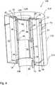
1 einen perspektivischen Längsschnitt durch ein Filtersystem nach einem Ausführungsbeispiel der Erfindung mit einem Sekundärelement in einer ersten Betriebsposition und offenem Filtergehäuse;2 einen perspektivischen Längsschnitt durch das Filtersystem in1 mit dem Sekundärelement in einer zweiten Betriebsposition;3 einen perspektivischen Längsschnitt durch das Filtersystem in1 mit dem Sekundärelement in einer zweiten Betriebsposition bei der Entnahme des Filterelements; und4 einen perspektivischen Längsschnitt durch das Filtersystem in1 mit dem Sekundärelement in der ersten Betriebsposition und geschlossenem Filtergehäuse.
1 a perspective longitudinal section through a filter system according to an embodiment of the invention with a secondary element in a first operating position and open filter housing;2 a perspective longitudinal section through the filter system in1 with the secondary element in a second operating position;3 a perspective longitudinal section through the filter system in1 with the secondary element in a second operating position during the removal of the filter element; and4 a perspective longitudinal section through the filter system in1 with the secondary element in the first operating position and closed filter housing.
Ausführungsformen der ErfindungEmbodiments of the invention
In den Figuren sind gleiche oder gleichartige Komponenten mit gleichen Bezugszeichen beziffert. Die Figuren zeigen lediglich Beispiele und sind nicht beschränkend zu verstehen.In the figures, the same or similar components are numbered with the same reference numerals. The figures are merely examples and are not intended to be limiting.
Das Filtersystem
Weiter ist in dem Filtergehäuse
Das Filterelement
Das Sekundärelement
In
Zum Austausch des Filterelements
Beim Einsetzen eines neuen Filterelements
ZITATE ENTHALTEN IN DER BESCHREIBUNG QUOTES INCLUDE IN THE DESCRIPTION
Diese Liste der vom Anmelder aufgeführten Dokumente wurde automatisiert erzeugt und ist ausschließlich zur besseren Information des Lesers aufgenommen. Die Liste ist nicht Bestandteil der deutschen Patent- bzw. Gebrauchsmusteranmeldung. Das DPMA übernimmt keinerlei Haftung für etwaige Fehler oder Auslassungen.This list of the documents listed by the applicant has been generated automatically and is included solely for the better information of the reader. The list is not part of the German patent or utility model application. The DPMA assumes no liability for any errors or omissions.
Zitierte PatentliteraturCited patent literature
- EP 1163039 B1 [0002]EP 1163039 B1 [0002]
Claims (16)
Translated fromGermanPriority Applications (6)
| Application Number | Priority Date | Filing Date | Title |
|---|---|---|---|
| DE102017005797.4ADE102017005797A1 (en) | 2017-06-21 | 2017-06-21 | Filter system with filter element and secondary element |
| CN201880042282.8ACN110769914B (en) | 2017-06-21 | 2018-06-15 | Filter system comprising a filter element for closing a central tube and an auxiliary element |
| BR112019021203ABR112019021203A2 (en) | 2017-06-21 | 2018-06-15 | filter system with filter element and secondary element for closing a central tube |
| EP18733548.4AEP3641909B1 (en) | 2017-06-21 | 2018-06-15 | Filter system with filter elemetn and secondary element for closing a central tube |
| PCT/EP2018/065966WO2018234182A1 (en) | 2017-06-21 | 2018-06-15 | FILTERING SYSTEM WITH FILTER ELEMENT AND SECONDARY ELEMENT FOR CLOSING A MEDIUM TUBE |
| US16/723,420US11890558B2 (en) | 2017-06-21 | 2019-12-20 | Filter system comprising a filter element and secondary element for closing a central tube |
Applications Claiming Priority (1)
| Application Number | Priority Date | Filing Date | Title |
|---|---|---|---|
| DE102017005797.4ADE102017005797A1 (en) | 2017-06-21 | 2017-06-21 | Filter system with filter element and secondary element |
Publications (1)
| Publication Number | Publication Date |
|---|---|
| DE102017005797A1true DE102017005797A1 (en) | 2018-12-27 |
Family
ID=62712970
Family Applications (1)
| Application Number | Title | Priority Date | Filing Date |
|---|---|---|---|
| DE102017005797.4ACeasedDE102017005797A1 (en) | 2017-06-21 | 2017-06-21 | Filter system with filter element and secondary element |
Country Status (6)
| Country | Link |
|---|---|
| US (1) | US11890558B2 (en) |
| EP (1) | EP3641909B1 (en) |
| CN (1) | CN110769914B (en) |
| BR (1) | BR112019021203A2 (en) |
| DE (1) | DE102017005797A1 (en) |
| WO (1) | WO2018234182A1 (en) |
Cited By (4)
| Publication number | Priority date | Publication date | Assignee | Title |
|---|---|---|---|---|
| WO2021219565A1 (en)* | 2020-04-27 | 2021-11-04 | Shell Internationale Research Maatschappij B.V. | Gas phase settling (gps) tray |
| WO2022194544A1 (en)* | 2021-03-17 | 2022-09-22 | Mann+Hummel Gmbh | Filter element and filter system |
| DE102022124022A1 (en)* | 2022-09-20 | 2024-03-21 | Mann+Hummel Gmbh | Gas filter system |
| EP4342562A1 (en) | 2022-09-20 | 2024-03-27 | MANN+HUMMEL GmbH | Gas filter system |
Families Citing this family (3)
| Publication number | Priority date | Publication date | Assignee | Title |
|---|---|---|---|---|
| CN112604394A (en)* | 2020-12-15 | 2021-04-06 | 芜湖澳奔玛汽车部件有限公司 | Filter convenient to change filter core board |
| US12214295B2 (en)* | 2021-11-02 | 2025-02-04 | Gene Pool Technologies, Inc. | Solvent-extract filter apparatuses and methods |
| CN114534398B (en)* | 2022-02-24 | 2024-04-09 | 江苏中瑞咨询有限公司 | Comprehensive treatment device for dust-containing waste gas |
Citations (3)
| Publication number | Priority date | Publication date | Assignee | Title |
|---|---|---|---|---|
| EP1163039B1 (en) | 1999-03-24 | 2003-06-04 | FILTERWERK MANN + HUMMEL GmbH | Filter with a conical housing and round filter cartridge |
| US20040065602A1 (en)* | 2002-10-08 | 2004-04-08 | Pti Technologies, Inc. | Fatigue rated glass filled plastic filter assembly incorporating a coreless plastic filter element with integral seal |
| US20150217218A1 (en)* | 2014-02-04 | 2015-08-06 | Caterpillar Inc. | Filter element |
Family Cites Families (24)
| Publication number | Priority date | Publication date | Assignee | Title |
|---|---|---|---|---|
| DE2618098C3 (en)* | 1976-04-24 | 1978-10-12 | Wilhelm Schuler, Filtertechnik Gmbh, 6719 Eisenberg | Filter apparatus with granular filter material |
| US5215655A (en)* | 1991-10-28 | 1993-06-01 | Tokheim Corporation | Dispenser interlock fuel filter system disabled in response to filter removal |
| US5350506A (en)* | 1992-01-30 | 1994-09-27 | Navistar International Transporation Corporation | Anti-drain fluid filter |
| US5468386A (en)* | 1993-03-19 | 1995-11-21 | Ing. Walter Hengst Gmbh & Co. Kg | Filter assembly and preassembled drain valve unit therefor |
| US5549722A (en) | 1994-12-30 | 1996-08-27 | Dana Corporation | Air filter assemblies and a frustoconical air filter element for use with the assemblies |
| DE19933205C2 (en) | 1999-07-15 | 2003-08-14 | Mahle Filtersysteme Gmbh | Use of a filter body of a fluid filter, in particular an air filter |
| DE10049313A1 (en) | 2000-10-05 | 2002-04-11 | Audi Ag | Housing for reception of air filter element with housing base and housing lid for IC engine of working vehicle |
| MXPA03009907A (en)* | 2001-05-02 | 2004-01-29 | Parker Hannifin Corp | Spin-on filter element and corresponding filter head. |
| US6607665B2 (en)* | 2001-07-17 | 2003-08-19 | Baldwin Filters, Inc. | Fuel filter element and cover assembly |
| DE10135080A1 (en) | 2001-07-18 | 2003-01-30 | Mahle Filtersysteme Gmbh | Cylindrical fan-fold automotive filter insert comprises fan-folded panel bent into tubular form and held between ring-shaped end caps |
| US20040069700A1 (en)* | 2002-10-09 | 2004-04-15 | Miller Terry L. | Fuel filter assembly, and a method of changing a fuel filter within a fuel system |
| US7056432B2 (en)* | 2003-02-21 | 2006-06-06 | Deere & Company | Tank mounted oil filter assembly |
| JP2006035208A (en) | 2004-06-23 | 2006-02-09 | Komatsu Ltd | Air cleaner |
| KR100712266B1 (en)* | 2005-03-24 | 2007-05-17 | 주식회사 피코그램 | Water filter easily replaced using a connector, and water purification device using the same |
| EP2664372A1 (en) | 2006-10-06 | 2013-11-20 | Donaldson Company, Inc. | Air cleaner, replaceable filter cartridges, and methods |
| DE102009007389B3 (en)* | 2009-02-05 | 2010-04-15 | Hydac Filtertechnik Gmbh | filter means |
| DE102009054523A1 (en)* | 2009-12-10 | 2011-06-16 | Hengst Gmbh & Co. Kg | liquid filters |
| DE102011005106A1 (en)* | 2011-02-18 | 2012-08-23 | Hengst Gmbh & Co. Kg | Bypass valve, facility with bypass valve and filter element of the device |
| ITAN20110048A1 (en)* | 2011-04-13 | 2012-10-14 | Sifim Srl | FILTER FOR SUCTION HOODS |
| US9702794B2 (en)* | 2011-12-27 | 2017-07-11 | Koninklijke Philips N.V. | User replaceable filter for gas sampling system |
| DE202013011868U1 (en)* | 2013-09-02 | 2014-12-03 | Mann+Hummel Gmbh | Filter system and filter element for a filter system |
| DE102013017667B4 (en)* | 2013-10-25 | 2016-07-14 | Mann + Hummel Gmbh | Filter element with a bypass channel and filter assembly with a filter element |
| EP3810302B1 (en)* | 2018-06-22 | 2024-02-07 | Volvo Truck Corporation | Filter element, liquid filtering device comprising such a filter element and vehicle comprising such a liquid filtering device |
| US20200190779A1 (en)* | 2018-12-14 | 2020-06-18 | Elmer Richard Wagner | Remote back-flow detecton & shut-off system |
- 2017
- 2017-06-21DEDE102017005797.4Apatent/DE102017005797A1/ennot_activeCeased
- 2018
- 2018-06-15BRBR112019021203Apatent/BR112019021203A2/ennot_activeApplication Discontinuation
- 2018-06-15CNCN201880042282.8Apatent/CN110769914B/enactiveActive
- 2018-06-15WOPCT/EP2018/065966patent/WO2018234182A1/ennot_activeCeased
- 2018-06-15EPEP18733548.4Apatent/EP3641909B1/enactiveActive
- 2019
- 2019-12-20USUS16/723,420patent/US11890558B2/enactiveActive
Patent Citations (3)
| Publication number | Priority date | Publication date | Assignee | Title |
|---|---|---|---|---|
| EP1163039B1 (en) | 1999-03-24 | 2003-06-04 | FILTERWERK MANN + HUMMEL GmbH | Filter with a conical housing and round filter cartridge |
| US20040065602A1 (en)* | 2002-10-08 | 2004-04-08 | Pti Technologies, Inc. | Fatigue rated glass filled plastic filter assembly incorporating a coreless plastic filter element with integral seal |
| US20150217218A1 (en)* | 2014-02-04 | 2015-08-06 | Caterpillar Inc. | Filter element |
Cited By (7)
| Publication number | Priority date | Publication date | Assignee | Title |
|---|---|---|---|---|
| WO2021219565A1 (en)* | 2020-04-27 | 2021-11-04 | Shell Internationale Research Maatschappij B.V. | Gas phase settling (gps) tray |
| CN115397541A (en)* | 2020-04-27 | 2022-11-25 | 国际壳牌研究有限公司 | Vapor deposition (GPS) tray |
| WO2022194544A1 (en)* | 2021-03-17 | 2022-09-22 | Mann+Hummel Gmbh | Filter element and filter system |
| DE102021106524A1 (en) | 2021-03-17 | 2022-09-22 | Mann+Hummel Gmbh | Filter element and filter system |
| DE102022124022A1 (en)* | 2022-09-20 | 2024-03-21 | Mann+Hummel Gmbh | Gas filter system |
| EP4342562A1 (en) | 2022-09-20 | 2024-03-27 | MANN+HUMMEL GmbH | Gas filter system |
| WO2024061490A1 (en) | 2022-09-20 | 2024-03-28 | Mann+Hummel Gmbh | Gas filter system |
Also Published As
| Publication number | Publication date |
|---|---|
| BR112019021203A2 (en) | 2020-04-28 |
| CN110769914B (en) | 2022-03-04 |
| WO2018234182A1 (en) | 2018-12-27 |
| CN110769914A (en) | 2020-02-07 |
| EP3641909A1 (en) | 2020-04-29 |
| EP3641909B1 (en) | 2021-10-20 |
| US20200197842A1 (en) | 2020-06-25 |
| US11890558B2 (en) | 2024-02-06 |
Similar Documents
| Publication | Publication Date | Title |
|---|---|---|
| EP3641909B1 (en) | Filter system with filter elemetn and secondary element for closing a central tube | |
| EP1307274B1 (en) | Liquid filter, especially for lubricating oil of a combustion engine | |
| DE102013017667B4 (en) | Filter element with a bypass channel and filter assembly with a filter element | |
| DE102014016301A1 (en) | Hollow filter element of a filter for filtering fluid, filter, filter housing and sealing a hollow filter element | |
| DE102014006853A1 (en) | Hollow filter element, filter housing and filter | |
| DE202014011016U1 (en) | Cup-shaped housing and device for separating liquid from air | |
| WO2014082762A1 (en) | Filter, filter element, filter housing and discharge device of a filter | |
| DE102014016300A1 (en) | Filter, hollow filter element and filter housing of a filter and sealing a hollow filter element | |
| DE102013012918A1 (en) | Liquid filter, in particular for fuel | |
| EP3197581B1 (en) | Filter element, filter and filter system with return bypass | |
| DE102016001023A1 (en) | Filter element and fluid filter | |
| DE102008027374A1 (en) | Filter for equipment of an internal combustion engine, and components of such a filter | |
| DE102014011394A1 (en) | Oil filter element and oil filter | |
| DE102013012917A1 (en) | Liquid filter, in particular for fuel | |
| DE102013020539A1 (en) | filter element | |
| DE102017009255A1 (en) | Filter element with ventilation function for hanging connection to a filter head and filter system | |
| WO2018146102A1 (en) | Fuel filter comprising a filter insert with a prefilter element and a main filter element | |
| DE102007014813A1 (en) | filter means | |
| DE102006045985A1 (en) | Filter device, in particular for the filtration of combustion air in internal combustion engines | |
| DE102018004158A1 (en) | Intermediate cover of a filter housing of a filter for cleaning liquid fluids and filter cartridge | |
| EP3727641B1 (en) | Filter system with non-return valve and filter element | |
| DE102005007019A1 (en) | filter system | |
| DE102021112122A1 (en) | Filter element for a filter system with a resonator structure and filter system with a resonator structure | |
| DE102015008693A1 (en) | Hollow filter element of a filter for fluid, filter and filter housing | |
| DE102015117283A1 (en) | Desiccant cartridge with improved drying and regeneration |
Legal Events
| Date | Code | Title | Description |
|---|---|---|---|
| R012 | Request for examination validly filed | ||
| R002 | Refusal decision in examination/registration proceedings | ||
| R003 | Refusal decision now final |