DE102017004885A1 - Method for estimating the achievable total braking forces for automated deceleration of a commercial vehicle, brake system and commercial vehicle with it - Google Patents
Method for estimating the achievable total braking forces for automated deceleration of a commercial vehicle, brake system and commercial vehicle with itDownload PDFInfo
- Publication number
- DE102017004885A1 DE102017004885A1DE102017004885.1ADE102017004885ADE102017004885A1DE 102017004885 A1DE102017004885 A1DE 102017004885A1DE 102017004885 ADE102017004885 ADE 102017004885ADE 102017004885 A1DE102017004885 A1DE 102017004885A1
- Authority
- DE
- Germany
- Prior art keywords
- brake
- braking forces
- achievable
- determined
- vehicle
- Prior art date
- Legal status (The legal status is an assumption and is not a legal conclusion. Google has not performed a legal analysis and makes no representation as to the accuracy of the status listed.)
- Withdrawn
Links
- 238000000034methodMethods0.000titleclaimsabstractdescription22
- 238000013461designMethods0.000claimsdescription10
- 230000001133accelerationEffects0.000description5
- 238000005096rolling processMethods0.000description5
- 238000005259measurementMethods0.000description3
- 230000000903blocking effectEffects0.000description2
- 238000010586diagramMethods0.000description2
- 239000000446fuelSubstances0.000description2
- BUHVIAUBTBOHAG-FOYDDCNASA-N(2r,3r,4s,5r)-2-[6-[[2-(3,5-dimethoxyphenyl)-2-(2-methylphenyl)ethyl]amino]purin-9-yl]-5-(hydroxymethyl)oxolane-3,4-diolChemical compoundCOC1=CC(OC)=CC(C(CNC=2C=3N=CN(C=3N=CN=2)[C@H]2[C@@H]([C@H](O)[C@@H](CO)O2)O)C=2C(=CC=CC=2)C)=C1BUHVIAUBTBOHAG-FOYDDCNASA-N0.000description1
- FXNSVEQMUYPYJS-UHFFFAOYSA-N4-(2-aminoethyl)benzenesulfonamideChemical compoundNCCC1=CC=C(S(N)(=O)=O)C=C1FXNSVEQMUYPYJS-UHFFFAOYSA-N0.000description1
- 108091081062Repeated sequence (DNA)Proteins0.000description1
- 230000003321amplificationEffects0.000description1
- 230000005540biological transmissionEffects0.000description1
- 238000001514detection methodMethods0.000description1
- 238000003912environmental pollutionMethods0.000description1
- ZINJLDJMHCUBIP-UHFFFAOYSA-Nethametsulfuron-methylChemical compoundCCOC1=NC(NC)=NC(NC(=O)NS(=O)(=O)C=2C(=CC=CC=2)C(=O)OC)=N1ZINJLDJMHCUBIP-UHFFFAOYSA-N0.000description1
- 238000011156evaluationMethods0.000description1
- 238000011835investigationMethods0.000description1
- 238000012423maintenanceMethods0.000description1
- 238000003199nucleic acid amplification methodMethods0.000description1
- 230000035484reaction timeEffects0.000description1
- 238000009987spinningMethods0.000description1
- 238000012360testing methodMethods0.000description1
Images

Classifications
- B—PERFORMING OPERATIONS; TRANSPORTING
- B60—VEHICLES IN GENERAL
- B60T—VEHICLE BRAKE CONTROL SYSTEMS OR PARTS THEREOF; BRAKE CONTROL SYSTEMS OR PARTS THEREOF, IN GENERAL; ARRANGEMENT OF BRAKING ELEMENTS ON VEHICLES IN GENERAL; PORTABLE DEVICES FOR PREVENTING UNWANTED MOVEMENT OF VEHICLES; VEHICLE MODIFICATIONS TO FACILITATE COOLING OF BRAKES
- B60T8/00—Arrangements for adjusting wheel-braking force to meet varying vehicular or ground-surface conditions, e.g. limiting or varying distribution of braking force
- B60T8/17—Using electrical or electronic regulation means to control braking
- B60T8/172—Determining control parameters used in the regulation, e.g. by calculations involving measured or detected parameters
- B—PERFORMING OPERATIONS; TRANSPORTING
- B60—VEHICLES IN GENERAL
- B60T—VEHICLE BRAKE CONTROL SYSTEMS OR PARTS THEREOF; BRAKE CONTROL SYSTEMS OR PARTS THEREOF, IN GENERAL; ARRANGEMENT OF BRAKING ELEMENTS ON VEHICLES IN GENERAL; PORTABLE DEVICES FOR PREVENTING UNWANTED MOVEMENT OF VEHICLES; VEHICLE MODIFICATIONS TO FACILITATE COOLING OF BRAKES
- B60T7/00—Brake-action initiating means
- B60T7/12—Brake-action initiating means for automatic initiation; for initiation not subject to will of driver or passenger
- B—PERFORMING OPERATIONS; TRANSPORTING
- B60—VEHICLES IN GENERAL
- B60T—VEHICLE BRAKE CONTROL SYSTEMS OR PARTS THEREOF; BRAKE CONTROL SYSTEMS OR PARTS THEREOF, IN GENERAL; ARRANGEMENT OF BRAKING ELEMENTS ON VEHICLES IN GENERAL; PORTABLE DEVICES FOR PREVENTING UNWANTED MOVEMENT OF VEHICLES; VEHICLE MODIFICATIONS TO FACILITATE COOLING OF BRAKES
- B60T8/00—Arrangements for adjusting wheel-braking force to meet varying vehicular or ground-surface conditions, e.g. limiting or varying distribution of braking force
- B60T8/17—Using electrical or electronic regulation means to control braking
- B60T8/1701—Braking or traction control means specially adapted for particular types of vehicles
- B60T8/1708—Braking or traction control means specially adapted for particular types of vehicles for lorries or tractor-trailer combinations
- B—PERFORMING OPERATIONS; TRANSPORTING
- B60—VEHICLES IN GENERAL
- B60T—VEHICLE BRAKE CONTROL SYSTEMS OR PARTS THEREOF; BRAKE CONTROL SYSTEMS OR PARTS THEREOF, IN GENERAL; ARRANGEMENT OF BRAKING ELEMENTS ON VEHICLES IN GENERAL; PORTABLE DEVICES FOR PREVENTING UNWANTED MOVEMENT OF VEHICLES; VEHICLE MODIFICATIONS TO FACILITATE COOLING OF BRAKES
- B60T2250/00—Monitoring, detecting, estimating vehicle conditions
- B60T2250/02—Vehicle mass
Landscapes
- Engineering & Computer Science (AREA)
- Transportation (AREA)
- Mechanical Engineering (AREA)
- Regulating Braking Force (AREA)
Abstract
Translated fromGerman
Description
Translated fromGermanDie Erfindung betrifft ein Verfahren zur Schätzung der erreichbaren Gesamtbremskräfte zur automatisierten Verzögerung eines Nutzfahrzeugs oder einer Fahrzeugkombination mit mehreren Achsen gemäß Anspruch 1. Die Erfindung betrifft außerdem gemäß Anspruch 9 eine Bremsanlage zur Durchführung des Verfahrens sowie gemäß Anspruch 11 ein Nutzfahrzeug oder eine Fahrzeugkombination mit einer solchen Bremsanlage.The invention relates to a method for estimating the achievable total braking forces for automated deceleration of a commercial vehicle or a vehicle combination with multiple axes according to
Bei modernen Nutzfahrzeug werden zunehmend automatisierte Bremssysteme eingesetzt, beispielsweise fortschrittliche Notbremssysteme (AEBS = „advanced emergency braking system“), Fahrerassistenzsysteme wie elektronische Stabilitätskontrollen (ESC), wobei die Bremsanlage über eine elektronische Bremssteuereinheit unabhängig von Fahrerbremsungen bedarfsweise automatisiert das Fahrzeug verzögert. Von besonderer Bedeutung ist dabei die möglichst genaue Kenntnis der zur Verfügung stehenden Gesamtbremskraft des Nutzfahrzeugs. Dies gilt in besonderem Maße für das sogenannte Platooning, wobei mehrere Nutzfahrzeuge oder Fahrzeugkombinationen im Straßenverkehr mit Hilfe einer koordinierenden Steuerung mit möglichst geringem Abstand hintereinander fahren, um den Kraftstoffverbrauch zu verringern. Die Nutzfahrzeuge des Platoons sind miteinander vernetzt oder weisen Einrichtungen zur Abstandmessung wie RADAR oder LIDAR auf, welche der Einstellung möglichst geringer Abstände zum vorausfahrenden Fahrzeug dienen, ohne dass die Verkehrssicherheit beeinträchtigt wird. Die vernetzten Nutzfahrzeuge im Platoon benötigen aufgrund kurzer Reaktionszeiten der automatisierten Verzögerung einen deutlich geringeren Abstand als bei manueller Fahrzeugführung, wodurch sich der Luftwiderstand erheblich reduziert.In modern commercial vehicle increasingly automated braking systems are used, such as advanced emergency braking systems (AEBS = advanced emergency braking system), driver assistance systems such as electronic stability controls (ESC), the brake system automatically retards the vehicle via an electronic brake control unit regardless of driver braking as needed. Of particular importance is the most accurate knowledge possible of the available total braking force of the commercial vehicle. This is particularly true for the so-called platooning, with several commercial vehicles or vehicle combinations driving in the road with the help of a coordinating control with the shortest possible distance behind each other to reduce fuel consumption. The platoon commercial vehicles are networked with each other or have distance measuring devices such as RADAR or LIDAR, which serve to set as close as possible distances to the vehicle in front without impairing traffic safety. The networked commercial vehicles in the platoon require a much shorter distance due to the short reaction times of the automated deceleration than with manual vehicle guidance, as a result of which the air resistance is considerably reduced.
Um den Abstand jedoch so gering wie möglich zu halten ist eine möglichst genaue Kenntnis des minimal benötigten Sicherheitsabstands erforderlich, welcher maßgeblich von der maximal verfügbaren Bremskraft eines Nutzfahrzeugs oder einer Fahrzeugkombination im Platoon abhängt. Die erreichbaren Gesamtbremskräfte eines Nutzfahrzeugs oder einer Fahrzeugkombination hängen von einer Vielzahl von Faktoren ab, insbesondere dem Bremsenkennwert der Radbremsen, welcher die Abhängigkeit des von der Radbremse aufgebrachten Bremsmoments von dem aufgebrachten Bremsdruck repräsentiert. Neben diesem Bremsenkennwert haben auch konstruktiv gegebene Eigenschaften einzelner Bremsen und auch Reifen sowie die Fahrbahnreibung Einfluss auf die erreichbaren Bremskräfte.However, in order to keep the distance as small as possible, it is necessary to have as accurate a knowledge as possible of the minimum required safety distance, which depends decisively on the maximum available braking force of a commercial vehicle or a vehicle combination in the platoon. The achievable total braking forces of a commercial vehicle or a vehicle combination depend on a multiplicity of factors, in particular the brake characteristic value of the wheel brakes, which represents the dependence of the braking torque applied by the wheel brake on the applied brake pressure. In addition to this brake characteristic also structurally given properties of individual brakes and tires and the road friction have an influence on the achievable braking forces.
Das Aufzeichnen von erreichten Bremskräften während der Fahrt des Nutzfahrzeugs stellt regelmäßig keine verlässlichen Informationen zur maximalen Verzögerung bereit, da hierfür die Durchführung einer Vollbremsung erforderlich wäre. Eine Messung der aktuell erreichbaren Gesamtbremskräfte könnte grundsätzlich zwar durch Bremsversuche ermittelt werden, der Aufwand zur Messung der erreichbaren Gesamtkräfte ist jedoch aufwendig und müsste häufig durchgeführt werden, beispielsweise nach jeder Änderung des Beladungszustands des Nutzfahrzeugs oder einer Fahrzeugkombination. Da dies kaum praktikabel ist, bleiben die erreichbaren Gesamtbremskräfte, insbesondere die maximal erreichbare Bremskraft eines Nutzfahrzeugs oder einer Fahrzeugkombination, unbekannt. Das Potential des Platoonings zur Reduzierung des Kraftstoffverbrauchs kann ohne verlässliche Informationen zu den erreichbaren Gesamtbremskräften nicht ausgeschöpft werden.The recording of achieved braking forces during the drive of the commercial vehicle regularly provides no reliable information for the maximum delay, since this would require the implementation of full braking would be required. A measurement of the currently achievable total braking forces could basically be determined by braking tests, the effort to measure the achievable total forces is complex and would have to be performed frequently, for example, after each change in the load state of the commercial vehicle or a vehicle combination. Since this is hardly practicable, the achievable total braking forces, in particular the maximum achievable braking force of a commercial vehicle or a vehicle combination remain unknown. The potential of platooning to reduce fuel consumption can not be exploited without reliable information on the achievable total braking forces.
Der vorliegenden Erfindung liegt die Aufgabe zugrunde, die erreichbaren Gesamtkräfte zur Verzögerung eines Nutzfahrzeugs oder einer Fahrzeugkombination mit mehreren Achsen im laufenden Betrieb möglichst genau zu schätzen.The present invention has the object of estimating the achievable total forces for deceleration of a commercial vehicle or a vehicle combination with multiple axes during operation as accurately as possible.
Diese Aufgabe wird erfindungsgemäß durch ein Verfahren zur Schätzung der erreichbaren Gesamtkräfte zur automatisierten Verzögerung mit den Merkmalen des Anspruchs 1 gelöst. Die Erfindung wird außerdem gemäß Anspruch 9 durch eine Bremsanlage zur Durchführung des Verfahrens und gemäß Anspruch 11 durch ein Nutzfahrzeug oder eine Fahrzeugkombination mit einer derartigen Bremsanlage gelöst.This object is achieved by a method for estimating the achievable total forces for automated deceleration with the features of
Erfindungsgemäß werden in Schätzbremsungen für einzelne Bremseneinheiten, welche aus mindestens einer der Radbremsen bestehen, Bremsenkennwerte als Verhältnis der Teilbremskraft und dem dafür eingestellten Bremsdruck unter Berücksichtigung der aktuellen, der dabei erreichten, Verzögerung des Nutzfahrzeugs beziehungsweise der Fahrzeugkombination in der nachstehend beschriebenen Weise ermittelt. Unter einem Nutzfahrzeug wird dabei ein Kraftfahrzeug verstanden, welches nach seiner Bauart für den Transport von Gütern (beispielsweise Lastkraftwagen, Zugfahrzeug und dergleichen) oder den Transport von Personen (beispielsweise Omnibusse) oder aber zum Ziehen von Anhängern bestimmt ist. Eine Fahrzeugkombination umfasst ein motorisiertes Zugfahrzeug und wenigstens ein Anhängefahrzeug.According to the invention, in estimation braking for individual brake units, which consist of at least one of the wheel brakes, brake characteristic values are expressed as the ratio of the partial braking force and the brake pressure set for it, taking into account the current, the achieved, Delay of the commercial vehicle or the vehicle combination determined in the manner described below. Under a commercial vehicle while a motor vehicle is understood, which is determined by its design for the transport of goods (for example, trucks, towing vehicle and the like) or the transport of persons (for example, buses) or for towing trailers. A vehicle combination comprises a motorized towing vehicle and at least one trailer vehicle.
Vorteilhaft werden die Bremsenkennwerte für Bremseneinheiten mit Radbremsen einzelner Achsen oder Gruppen von Achsen ermittelt, so dass bei der Schätzbremsung stabile Bremsverhältnisse vorherrschen. Ist die Stabilität des Nutzfahrzeugs oder des Fahrzeuggespanns in einer konkreten Bremssituation nicht gefährdet, können in einer Ausführungsform der Erfindung auch einzelne Radbremsen als Bremseneinheit im erfindungsgemäßen Sinn bewertet werden, beziehungsweise ein Bremsenkennwert für eine aktive Radbremse und die mit dieser Radbremse erreichbaren Gesamtkräfte geschätzt werden. Die Radbremsen von Gruppen von Achsen werden als Bremseneinheiten im erfindungsgemäßen Sinn bewertet, insbesondere bei Ausführungsformen, bei denen die Radbremsen mehrerer Achsen in einem gemeinsamen Bremskreis, beispielsweise über denselben Druckmodulator angesteuert werden. Die aktuelle Verzögerung wird aus Messwerten ermittelt, beispielsweise aus den Messwerten eines Beschleunigungssensors. Der Beschleunigungssensor ist dabei der Bremssteuereinheit derart zugeordnet, dass die Bremssteuereinheit Zugriff auf die Messwerte des Beschleunigungssensors hat oder bereits ausgewertete Information zur aktuellen Verzögerung empfängt. In einer Ausführungsform der Erfindung werden Messwerte des Beschleunigungssensors eines Sensormoduls für die Stabilitätsregelung des Fahrzeugs herangezogen.The brake characteristics for brake units with wheel brakes of individual axles or groups of axles are advantageously determined so that stable braking conditions prevail in the estimation braking. If the stability of the commercial vehicle or of the vehicle combination in a specific braking situation is not jeopardized, in an embodiment of the invention individual wheel brakes can also be evaluated as a brake unit in the inventive sense, or a brake characteristic value for an active wheel brake and the total forces achievable with this wheel brake can be estimated. The wheel brakes of groups of axles are evaluated as brake units in the sense according to the invention, in particular in embodiments in which the wheel brakes of several axles are controlled in a common brake circuit, for example via the same pressure modulator. The current deceleration is determined from measured values, for example from the measured values of an acceleration sensor. The acceleration sensor is assigned to the brake control unit in such a way that the brake control unit has access to the measured values of the acceleration sensor or receives information already evaluated about the current deceleration. In one embodiment of the invention, measured values of the acceleration sensor of a sensor module are used for the stability control of the vehicle.
In einer vorteilhaften Ausführungsform wird die aktuelle Verzögerung aus den Messwerten von Drehzahlsensoren der Räder hergeleitet, so dass auf vorhandene Sensorhardware der Bremsanlage zurückgegriffen ist.In an advantageous embodiment, the current deceleration is derived from the measured values of rotational speed sensors of the wheels, so that existing brake hardware of the brake system is used.
Schätzbremsungen sind Verzögerungsvorgänge mit Umsetzung einer zur Verzögerung des Nutzfahrzeugs angeforderten Bremskraft, bei denen die angeforderte Bremskraft durch jeweils eine allein aktive Bremseneinheit wenigstens teilweise aufgebracht wird. Eine elektronische Steuereinheit der Bremsanlage ist dabei derart konfiguriert und ausgebildet, dass zur Durchführung der Schätzbremsungen einzelne Bremseneinheiten, also vorzugsweise die Radbremsen einzelner Achsen oder Gruppen von Achsen separat aktivierbar sind, also zur Umsetzung der Bremskraftanforderung unabhängig von den anderen Bremseneinheiten ansteuerbar sind. Der Erfindung liegt dabei die Erkenntnis zugrunde, dass die Leistungsfähigkeit der gesamten Bremsanlage bei höheren Bremsdrücken aus Sicherheitsgründen nicht erfasst werden kann, jedoch bei einer Durchführung von Schätzbremsungen mit lediglich einer aktiven Bremseneinheit diese Bremseneinheit zur Umsetzung der Bremskraftanforderung in einem Betriebspunkt mit höherem Bremsdruck arbeitet und so eine Schätzung, das heißt eine näherungsweise Bestimmung, der Teilbremskraft dieser Bremseneinheit bei gemeinsamer Betätigung mehrerer Radbremsen möglich ist. Mit einer Schätzung der jeweiligen Teilbremskräfte auch für höhere Bremsanforderungen sind nämlich Rückschlüsse auf die gemeinsame Leistungsfähigkeit der Bremseneinheiten möglich.Schätzbremsungen are deceleration operations with implementation of a required for deceleration of the commercial vehicle braking force, in which the requested braking force is applied at least partially by each alone active brake unit. An electronic control unit of the brake system is configured and configured such that individual brake units, ie preferably the wheel brakes of individual axles or groups of axles, can be separately activated to carry out the estimation braking, ie can be controlled independently of the other brake units to implement the braking force request. The invention is based on the finding that the performance of the entire brake system at higher brake pressures can not be detected for safety reasons, however, when performing estimation braking with only one active brake unit, this brake unit to implement the braking force requirement in an operating point with higher brake pressure works and so an estimate, that is an approximate determination of the partial braking force of this brake unit is possible with common operation of multiple wheel brakes. With an estimate of the respective partial braking forces even for higher braking requirements, conclusions about the joint performance of the brake units are possible.
Zur Bestimmung der erreichbaren Teilbremskräfte einer Bremseneinheit geht die Erfindung zunächst davon aus, dass sich das Bremsmoment einer Radbremse grundsätzlich proportional verhält zu dem aktuellen Wert der Stellgröße, welche zur Betätigung der Radbremse eingestellt ist, beispielsweise der aktuelle Bremsdruck. Die Proportion ist maßgeblich von einem Bremsenkennwert geprägt, welcher das Verhältnis der Teilbremskraft und der dafür eingestellten Stellgrößerepräsentiert.To determine the achievable partial braking forces of a brake unit, the invention initially assumes that the braking torque of a wheel brake basically proportional to the current value of the manipulated variable, which is set to actuate the wheel, for example, the current brake pressure. The proportion is significantly influenced by a brake characteristic which represents the ratio of the partial braking force and the manipulated variable set therefor.
Vorteilhaft werden die Radbremsen pneumatisch oder hydraulisch betätigt, wobei der Bremsdruck die Stellgröße ist. Entsprechend charakterisiert der Bremsenkennwert der Radbremse das Verhältnis des von der Radbremse generierten Bremsmoments zu dem dafür zwecks Betätigung aufgebrachten Bremsdruck. Mit einer hydraulischen Betätigung der Radbremsen lassen sich mit hoher Stellgenauigkeit hohe Bremsmomente und Bremskräfte einstellen. In einer weiteren vorteilhaften Ausführungsform sind elektromechanische Radbremsen vorgesehen. In der bevorzugten Ausführungsform werden die Radbremsen über ein pneumatisches Betätigungssystem in Betrieb genommen, wobei leistungsloses Druckhalten bei konstanter Kraft möglich ist und kleinere Leckagen keine Umweltbelastungen verursachen. Ferner sind pneumatische Bremssysteme vergleichsweise einfach aufgebaut und zudem in der Regel kostengünstiger als vergleichbare elektromechanische Bremssysteme.Advantageously, the wheel brakes are pneumatically or hydraulically actuated, wherein the brake pressure is the manipulated variable. Accordingly, the brake characteristic of the wheel brake characterizes the ratio of the braking torque generated by the wheel brake to the brake pressure applied for the purpose of actuation. With a hydraulic actuation of the wheel brakes can be adjusted with high positioning accuracy high braking torque and braking forces. In a further advantageous embodiment, electromechanical wheel brakes are provided. In the preferred embodiment, the wheel brakes are put into operation via a pneumatic actuation system, whereby powerless pressure maintenance at constant force is possible and smaller leaks do not cause environmental pollution. Furthermore, pneumatic brake systems are relatively simple and also generally cheaper than comparable electromechanical brake systems.
Bei der erfindungsgemäßen Schätzung der verfügbaren Bremskräfte wird zur Ermittlung des Bremsenkennwerts vorteilhaft auch ein jeweiliger Konstruktionsbeiwert berücksichtigt, welcher die bauartbedingte Charakteristik der beteiligten Radbremsen repräsentiert, beispielsweise die Hebelverhältnisse. Dieser Konstruktionsbeiwert ändert sich mit Betrieb der Bremsanlage nicht und wird im Voraus ermittelt und der erfindungsgemäßen Schätzung vorgegeben. Für das Bremsmoment an der Radbremse ergibt sich somit folgender Zusammenhang:
Dabei bezeichnet
- MB Bremsmoment
- P Bremsdruck (Stellgröße)
- CD Konstruktionsbeiwert
- CL Bremsenkennwert.
- MB braking torque
- P brake pressure (manipulated variable)
- CD design coefficient
- CL brake characteristic value.
Die Erfindung hat weiter erkannt, dass sich der Bremsenkennwert, welcher das Verhältnis der Teilbremskraft und der dafür eingestellten Stellgröße (wie Bremsdruck) repräsentiert, alternativ bestimmen lässt und sieht vor, aus dem so bestimmbaren Bremsenkennwert die erreichbaren Teilbremskräfte zu ermitteln. Die Bestimmung der erreichbaren Teilbremskräfte erfolgt dabei in jeweiligen Schätzbremsungen, so dass durch die Bildung der Summe der erreichbaren Teilbremskräfte Gesamtbremskräfte aller Radbremsen geschätzt werden können, ohne diese jedoch für die Schätzung gemeinsam betätigen zu müssen.The invention has further recognized that the brake characteristic value, which represents the ratio of the partial braking force and the manipulated variable set for it (such as brake pressure), can be determined alternatively and provides for determining the achievable partial braking forces from the brake characteristic value that can be determined in this way. The determination of the achievable partial braking forces takes place in each estimation braking, so that by forming the sum of the achievable partial braking forces total braking forces of all wheel brakes can be estimated, but without having to operate them together for the estimation.
Gemäß der Erfindung wird der Bremsenkennwert unter Berücksichtigung der aktuellen Verzögerung sowie einer ermittelten oder vorgegebenen Gesamtmasse des Nutzfahrzeugs oder der Fahrzeugkombination ermittelt. Unter Berücksichtigung der Gleichwertigkeit von Bremsmoment und dem Produkt aus Bremskraft und dynamischem Rollradius (FB =
In dieser Gleichung bezeichnet
- b aktuelle Verzögerung
- mtot Gesamtmasse des Fahrzeugs oder der Fahrzeugkombination
- rdyn dynamischer Rollradius.
- b current delay
- mtot Total mass of the vehicle or combination of vehicles
- rdyn dynamic rolling radius.
Aus dem so ermittelten Bremsenkennwert (CL1, CL2, CL3, CL4) wird erfindungsgemäß ein Rückschluß auf die von der jeweiligen Bremseneinheit (
Dabei bezeichnet
- FB erreichbare Teilbremskraft
- n laufende Nummer einer Bremseneinheit.
- FB achievable partial braking force
- n serial number of a brake unit.
Unter Berücksichtigung der ermittelten Bremsenkennwerte lässt sich somit die erreichbare Teilbremskraft einer jeden Bremseneinheit in Abhängigkeit des Bremsdrucks bestimmen, das heißt die erreichbare Teilbremskraft für jedes mögliche Niveau des Bremsdrucks zwischen einem Minimum und einem Maximum schätzen. Eine genaue Schätzung der erreichbaren Teilbremskräfte einer während der Schätzbremsung aktiven Bremseneinheit ist möglich, wenn die aktuelle Gesamtmasse des Fahrzeugs oder der Fahrzeugkombination berücksichtigt wird, welche im laufenden Betrieb gemessen wird. Es werden dadurch unterschiedliche Beladungszustände und damit unterschiedliche Achslasten bei der Schätzung der erreichbaren Gesamtbremskräfte zur automatisierten Verzögerung des Nutzfahrzeugs oder der Fahrzeugkombination berücksichtigt.Taking into account the determined brake characteristics, the achievable partial braking force of each brake unit can thus be determined as a function of the brake pressure, that is, estimate the achievable partial braking force for each possible level of brake pressure between a minimum and a maximum. An accurate estimate of the achievable partial braking forces of a brake unit active during the estimation braking is possible when taking into account the actual total mass of the vehicle or combination of vehicles measured during operation. Thereby, different load states and thus different axle loads are taken into account in the estimation of the achievable total braking forces for the automated deceleration of the commercial vehicle or the vehicle combination.
Die Genauigkeit der Schätzung der erreichbaren Gesamtbremskräfte ist weiter verbessert, wenn für die jeweiligen Bremseneinheiten Konstruktionsbeiwerte im Voraus ermittelt werden und bei der Schätzung der erreichbaren Teilbremskräfte vorgegeben werden.The accuracy of the estimation of the achievable total braking forces is further improved if design coefficients are determined in advance for the respective brake units and specified in the estimation of the achievable partial braking forces.
In einer vorteilhaften Ausführungsform der Erfindung wird eine Schätzbremsung unterlassen oder abgebrochen bei Anforderung von höheren Bremskräften als einer zuvor ermittelten erreichbaren Teilbremskraft für die aktive Bremseneinheit, so dass jedenfalls sichergestellt ist, dass die angeforderte Bremskraft bereit steht. Ein Unterlassen oder Abbrechen einer Schätzbremsung erfolgt vorteilhaft in Abhängigkeit einer Betrachtung des aktuellen Radschlupfs an der aktiven Bremseneinheit, wobei als Kriterium für die Durchführung von Schätzbremsungen ein Schwellwert für den Radschlupf vorgegeben ist, beispielsweise sieben Prozent. Überschreitet der Radschlupf den vorgegebenen Schwellwert, so wird zur Verzögerung des Nutzfahrzeugs beziehungsweise der Fahrzeugkombination die gesamte zur Verfügung stehende Bremsanlage eingesetzt und gewährleistet, dass Stabilitätsmaßnahmen ergriffen werden können, beispielsweise ein Antiblockiersystem eingreifen kann.In an advantageous embodiment of the invention, an estimation braking is omitted or canceled when requesting higher braking forces than a previously determined achievable partial braking force for the active brake unit, so that in any case it is ensured that the requested braking force is available. An omission or cancellation of an estimation braking is advantageously carried out as a function of a consideration of the current wheel slip on the active brake unit, wherein a threshold for the wheel slip is predetermined as a criterion for the performance of estimation braking, for example seven percent. If the wheel slip exceeds the predetermined threshold value, the entire available brake system is used to decelerate the commercial vehicle or the vehicle combination and ensures that stability measures can be taken, for example an anti-lock brake system can intervene.
Um sicher zu stellen, dass während der Schätzbremsungen bedarfsweise möglichst rasch die Gesamtbremskraft erhöht werden kann, wird während der Schätzbremsung für eine der Bremseneinheiten an den übrigen Radbremsen der Anlegedruck eingestellt.To ensure that the total braking force can be increased as quickly as possible during the estimation braking as needed, the application pressure is set during the estimation braking for one of the brake units on the other wheel brakes.
Die Schätzbremsungen werden für sämtliche Bremseneinheiten sukzessiv durchgeführt und wiederholt, so dass stets aktuelle Bremsenkennwerte und geschätzte Teilbremskräfte für die jeweiligen Bremseneinheiten zur Verfügung stehen, so dass stets die erreichbaren Gesamtbremskräfte, insbesondere die erreichbare Maximalbremskraft, geschätzt werden können. Die Wiederholung der Schätzbremsungen an einzelnen Bremseneinheiten erfolgt vorteilhaft nach einem vorgegebenen Wiederholungsmuster, beispielsweise periodisch bezüglich einer Reihenfolge der Bremseneinheiten. Bei der sukzessiven Durchführung der Schätzbremsungen für sämtliche Bremseneinheiten können bei der Umsetzung einer Bremsanforderung, das heißt während eines Verzögerungsvorgangs, hintereinander mehrere Schätzbremsungen durchgeführt werden. Erreicht während einer Schätzbremsung die aktive Bremseneinheit den gewünschten Betriebspunkt, so werden für den dabei anliegenden Bremsdruck sowie die dann gemessene und ermittelte Verzögerung des Fahrzeugs oder der Fahrzeugkombination die Bremsenkennwerte erfindungsgemäß ermittelt und die Teilbremskraft geschätzt. Die weitere Umsetzung der Bremskraftanforderung erfolgt dann durch eine weitere Bremseneinheit, welches hierzu allein aktiviert und von der Bremssteuereinheit angesteuert wird.The estimation brakes are successively performed and repeated for all brake units, so that always current brake characteristics and estimated partial braking forces are available for the respective brake units, so that the achievable total braking forces, in particular the achievable maximum braking force, are always estimated can be. The repetition of the estimation braking on individual brake units advantageously takes place according to a predetermined repetition pattern, for example periodically with respect to an order of the brake units. In the successive implementation of the estimation brakes for all brake units can be carried out in the implementation of a braking request, that is, during a deceleration process, consecutively several estimation brakes. If the active brake unit reaches the desired operating point during an estimation braking, then the brake characteristic values are determined according to the invention and the partial braking force is estimated for the applied brake pressure and the then measured and determined deceleration of the vehicle or vehicle combination. The further implementation of the braking force request is then carried out by a further brake unit, which is activated for this purpose alone and controlled by the brake control unit.
Ein Ausführungsbeispiel der Erfindung ist nachstehend anhand der Zeichnung näher erläutert. Es zeigen:
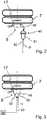
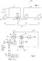
1 ein pneumatisches und elektrisches Schema einer Bremsanlage eines Nutzfahrzeugs gemäß einem ersten Ausführungsbeispiel mit pneumatischem Betätigungssystem,2 eine schematische Ansicht eines zweiten Ausführungsbeispiels mit hydraulischem Betätigungssystem,3 eine schematische Ansicht eines zweiten Ausführungsbeispiels mit hydraulischem Betätigungssystem,4 eine schematische Darstellung der Bremskräfte an einer Fahrzeugkombination mit mehreren Achsen,5 ein Flussschaubild eines Ausführungsbeispiels eines Verfahrens zur Schätzung der erreichbaren Gesamtbremskräfte in einerFahrzeugkombination gemäß 4 .
1 a pneumatic and electrical diagram of a brake system of a commercial vehicle according to a first embodiment with pneumatic actuation system,2 a schematic view of a second embodiment with hydraulic actuation system,3 a schematic view of a second embodiment with hydraulic actuation system,4 a schematic representation of the braking forces on a vehicle combination with multiple axes,5 a flowchart of an embodiment of a method for estimating the achievable total braking forces in a vehicle combination according to4 ,
In einem zweiten Ausführungsbeispiel ist ein hydraulisches Betätigungssystem
In einem dritten Ausführungsbeispiel gemäß
Die Bremsanlage
An den Rädern
Durch Auswertung der Drehzahlmesswerte schließt die Bremssteuereinheit
Die Achsmodulatoren
Die Bremssteuereinheit
Um beim Platooning den Abstand zum vorausfahrenden Fahrzeug so gering wie möglich zu halten, werden für das Fahrzeug oder die Fahrzeugkombination die erreichbaren Gesamtkräfte zur automatisierten Verzögerung geschätzt, was nachstehend anhand von
Während der Schätzbremsungen wird aus Messwerten
Das erfindungsgemäße Verfahren zur Schätzung der erreichbaren Gesamtbremskräfte ist nachstehend anhand eines Ausführungsbeispiels einer Fahrzeugkombination
Das Bremsmoment ist dabei proportional zu dem jeweils anliegenden Bremsdruck.The braking torque is proportional to the applied brake pressure.
Zur Schätzung der zur automatisierten Verzögerung erreichbaren Gesamtbremskräfte
Wie
Während der Schätzbremsung
Der Bremsenkennwert für die Bremseneinheit der vorderen Achse
In dem vorgenannten Zusammenhang ist allein der Bremsenkennwert CL1, welcher die Performance bzw. die Leistungsfähigkeit der Bremseneinheit repräsentiert, variabel. Der Konstruktionsbeiwert
Mit dem aktuell während der Schätzbremsung
Dabei wird bei dem Rückschluss
Dementsprechend werden in aufeinander folgenden Schätzbremsungen
Die Schätzbremsungen
Im gezeigten Ausführungsbeispiel werden die in unterschiedlichen Schätzbremsungen ermittelten Bremsenkennwerte cL1,CL2, cL3, cL4 in einer Kennwerttabelle 40 abgelegt und für die Zusammenstellung der Bremskrafttabelle 30 bereit gestellt, in welcher die erreichbaren Teilbremskräfte FB1, FB2, FB3, FB4 in Abhängigkeit des Bremsdruck
Im Ausführungsbeispiel mit elektromechanischer Betätigung wird bei den beschriebenen Schritten anstelle des Bremsdrucks
BezugszeichenlisteLIST OF REFERENCE NUMBERS
- 1.1.
- Achseaxis
- 2.Second
- Achseaxis
- 3.Third
- Achseaxis
- 4.4th
- Achseaxis
- 5.5th
- Bremsanlagebraking system
- 6.6th
- Nutzfahrzeugcommercial vehicle
- 7.7th
- Radwheel
- 8.8th.
- Radbremsewheel brake
- 9.9th
- Erster BremskreisFirst brake circuit
- 10.10th
- Erster DruckmittelvorratFirst pressure medium supply
- 11.11th
- Zweiter BremskreisSecond brake circuit
- 12.12th
- Zweiter DruckmittelvorratSecond pressure medium supply
- 13.13th
- Vorderer AchsmodulatorFront axle modulator
- 14.14th
- Hinterer AchsmodulatorRear axle modulator
- 15.15th
- Signalleitung (CAN)Signal line (CAN)
- 16.16th
- BremssteuereinheitBrake control unit
- 17.17th
- DrehzahlsensorSpeed sensor
- 18.18th
- Leitungmanagement
- 19.19th
- Ventilanordnungvalve assembly
- 20.20th
- Signalleitung (CAN)Signal line (CAN)
- 21.21st
- BremskraftanforderungBraking force demand
- 22.22nd
- BremssignalgeberBrake signal transmitter
- 23.23rd
- Bremspedalbrake pedal
- 24.24th
- Bremseneinheitbrake unit
- 25.25th
- Messwertreading
- 26.26th
- Beschleunigungssensoraccelerometer
- 27.27th
- Fahrzeugkombinationvehicle combination
- 28.28th
- Anhängefahrzeugtrailer
- 29.29th
- Schätzbremsungestimated braking
- 30.30th
- BremskrafttabelleBrake force Table
- 31.31st
- Summetotal
- 32.32nd
- Vergleichcomparison
- 33.33rd
- Normalbremsungnormal braking
- 34.34th
- Bewertungrating
- 35.35th
- Schwellwertthreshold
- 36.36th
- Bestimmungdetermination
- 37.37th
- Ermittlungdetection
- 38.38th
- Rückschlussconclusion
- 39.39th
- Auswahlselection
- 40.40th
- KennwerttabelleCharacteristic table
- 41.41st
- Externe BremskraftanforderungExternal braking force requirement
- 42.42nd
- Reihenfolgesequence
- 43.43rd
- Vorgabespecification
- 44.44th
- Betätigungssystem (pneumatisch)Actuating system (pneumatic)
- 45.45th
- Betätigungssystem (hydraulisch)Actuation system (hydraulic)
- 46.46th
- Betätigungssystem (elektromechanisch)Actuation system (electromechanical)
- 47.47th
- Pneumatischer BremszylinderPneumatic brake cylinder
- 48.48th
- Bremshebelbrake lever
- 49.49th
- Pneumatikleitungpneumatic line
- 50.50th
- Hydraulikleitunghydraulic line
- 51.51st
- Hydraulikzylinderhydraulic cylinders
- 52.52nd
- Elektromechanischer AktorElectromechanical actuator
- 53.53rd
- Elektrische SteuerleitungElectric control line
- FB1 - FB4FB1 - FB4
- TeilbremskraftPartial braking force
- mtotmdead
- Gesamtmassetotal mass
- m1 - m4 m1 - m4
- Achslastenaxle loads
- λλ
- Schlupfslippage
- MBMB
- Bremsmomentbraking torque
- CL1 - CL4CL1 - CL4
- BremsenkennwertBrake coefficient
- CD1CD1
- KonstruktionsbeiwertKonstruktionsbeiwert
- rdynrdyn
- dynamischer Rollradiusdynamic rolling radius
- PP
- Stellgröße BremsdruckControl value brake pressure
- PAPA
- Anlegedruckapply pressure
- II
- elektrische Stellgrößeelectrical manipulated variable
- bb
- aktuelle Verzögerungcurrent delay
- FGesFGes
- GesamtbremskraftTotal braking force
ZITATE ENTHALTEN IN DER BESCHREIBUNG QUOTES INCLUDE IN THE DESCRIPTION
Diese Liste der vom Anmelder aufgeführten Dokumente wurde automatisiert erzeugt und ist ausschließlich zur besseren Information des Lesers aufgenommen. Die Liste ist nicht Bestandteil der deutschen Patent- bzw. Gebrauchsmusteranmeldung. Das DPMA übernimmt keinerlei Haftung für etwaige Fehler oder Auslassungen.This list of the documents listed by the applicant has been generated automatically and is included solely for the better information of the reader. The list is not part of the German patent or utility model application. The DPMA assumes no liability for any errors or omissions.
Zitierte PatentliteraturCited patent literature
- DE 102008061944 A1 [0004]DE 102008061944 A1 [0004]
Claims (11)
Translated fromGermanPriority Applications (5)
| Application Number | Priority Date | Filing Date | Title |
|---|---|---|---|
| DE102017004885.1ADE102017004885A1 (en) | 2017-05-20 | 2017-05-20 | Method for estimating the achievable total braking forces for automated deceleration of a commercial vehicle, brake system and commercial vehicle with it |
| CN201880033172.5ACN110662677B (en) | 2017-05-20 | 2018-04-13 | Method for estimating the total braking force, braking device and commercial vehicle or vehicle combination |
| US16/611,231US11479221B2 (en) | 2017-05-20 | 2018-04-13 | Method for estimating the achievable total braking forces for the automated deceleration of a utility vehicle, braking system and utility vehicle having said braking system |
| EP18719487.3AEP3625094B1 (en) | 2017-05-20 | 2018-04-13 | Method for estimating the achievable total braking forces for the automated deceleration of a utility vehicle, braking system and utility vehicle having said braking system |
| PCT/EP2018/059507WO2018215135A1 (en) | 2017-05-20 | 2018-04-13 | Method for estimating the achievable total braking forces for the automated deceleration of a utility vehicle, braking system and utility vehicle having said braking system |
Applications Claiming Priority (1)
| Application Number | Priority Date | Filing Date | Title |
|---|---|---|---|
| DE102017004885.1ADE102017004885A1 (en) | 2017-05-20 | 2017-05-20 | Method for estimating the achievable total braking forces for automated deceleration of a commercial vehicle, brake system and commercial vehicle with it |
Publications (1)
| Publication Number | Publication Date |
|---|---|
| DE102017004885A1true DE102017004885A1 (en) | 2018-11-22 |
Family
ID=62044681
Family Applications (1)
| Application Number | Title | Priority Date | Filing Date |
|---|---|---|---|
| DE102017004885.1AWithdrawnDE102017004885A1 (en) | 2017-05-20 | 2017-05-20 | Method for estimating the achievable total braking forces for automated deceleration of a commercial vehicle, brake system and commercial vehicle with it |
Country Status (5)
| Country | Link |
|---|---|
| US (1) | US11479221B2 (en) |
| EP (1) | EP3625094B1 (en) |
| CN (1) | CN110662677B (en) |
| DE (1) | DE102017004885A1 (en) |
| WO (1) | WO2018215135A1 (en) |
Cited By (2)
| Publication number | Priority date | Publication date | Assignee | Title |
|---|---|---|---|---|
| CN112706621A (en)* | 2020-12-31 | 2021-04-27 | 北京金万安汽车电子技术研发有限公司 | Deceleration anti-shake control method of new energy vehicle tandem type energy recovery system |
| DE102022100289A1 (en) | 2022-01-07 | 2023-07-13 | Zf Cv Systems Global Gmbh | Method for determining the maximum possible braking deceleration of a vehicle and braking system for carrying out the method |
Families Citing this family (6)
| Publication number | Priority date | Publication date | Assignee | Title |
|---|---|---|---|---|
| US11285948B2 (en) | 2019-05-20 | 2022-03-29 | Caterpillar Inc. | Work machine speed control braking |
| DE102019208811A1 (en)* | 2019-06-18 | 2020-12-24 | Robert Bosch Gmbh | Device and method for determining at least one brake parameter of a hydraulic brake system of a vehicle |
| EP3964408B1 (en)* | 2020-09-04 | 2023-06-28 | KNORR-BREMSE Systeme für Nutzfahrzeuge GmbH | Method and equipment for estimating a braking factor for a braking system for a vehicle |
| JP7613964B2 (en) | 2021-03-19 | 2025-01-15 | トヨタ自動車株式会社 | Driving assistance device and method, and computer program |
| US12415496B2 (en)* | 2021-06-18 | 2025-09-16 | Volvo Truck Corporation | Method for assessing reliability of a brake assembly of a vehicle |
| CA3231887A1 (en)* | 2021-07-14 | 2023-01-19 | Stop-In-Time Gmbh | Method for braking a vehicle |
Citations (1)
| Publication number | Priority date | Publication date | Assignee | Title |
|---|---|---|---|---|
| DE102008061944A1 (en) | 2008-12-12 | 2010-06-17 | Wabco Gmbh | Brake controller for controlling brake system of e.g. bus, has braked axles designed for detecting movement characteristic value and for calculating brake characteristic value under consideration of current brake temperatures |
Family Cites Families (13)
| Publication number | Priority date | Publication date | Assignee | Title |
|---|---|---|---|---|
| DE3909588A1 (en)* | 1989-03-23 | 1990-09-27 | Bosch Gmbh Robert | METHOD FOR DETERMINING THE BRAKE TORQUE OF A VEHICLE |
| DE4210576C1 (en)* | 1992-03-31 | 1993-08-05 | Temic Telefunken Microelectronic Gmbh, 7100 Heilbronn, De | |
| DE4310422A1 (en)* | 1993-03-31 | 1994-07-21 | Telefunken Microelectron | Measuring vehicle brake application pressure |
| US5415466A (en)* | 1994-04-22 | 1995-05-16 | Eaton Corporation | System and method for determining relative brake factors |
| DE19517708B4 (en)* | 1995-05-13 | 2004-04-29 | Knorr-Bremse Systeme für Nutzfahrzeuge GmbH | Method and device for electronically controlling the brake system of a vehicle |
| WO1998014356A1 (en)* | 1996-09-30 | 1998-04-09 | Daimler-Benz Aktiengesellschaft | Control system for brake power proportioning on a road vehicle |
| JP4114044B2 (en)* | 2001-07-17 | 2008-07-09 | トヨタ自動車株式会社 | Tire acting force detection device |
| WO2003011669A1 (en)* | 2001-07-27 | 2003-02-13 | Continental Teves Ag & Co. Ohg | Method for analyzing the efficiency of wheel brakes in a brake system for a motor vehicle with at least two-axles |
| JP4415617B2 (en)* | 2003-09-11 | 2010-02-17 | 株式会社アドヴィックス | Brake control device |
| SE530440C2 (en)* | 2006-10-13 | 2008-06-10 | Volvo Lastvagnar Ab | Method and arrangement for measuring and estimating a braking factor in a vehicle's braking system |
| JP5007576B2 (en)* | 2007-02-21 | 2012-08-22 | 株式会社アドヴィックス | Vehicle behavior control device |
| JP5228209B2 (en)* | 2008-02-28 | 2013-07-03 | 日産自動車株式会社 | Vehicle braking force control device |
| DE102011087905A1 (en)* | 2011-12-07 | 2013-06-13 | Robert Bosch Gmbh | Brake system for e.g. electric car, has brake circuit connected to master brake cylinder and provided with wheel brake cylinder that exercises braking torque on wheel of vehicle, where wheel is assigned with wheel brake cylinder |
- 2017
- 2017-05-20DEDE102017004885.1Apatent/DE102017004885A1/ennot_activeWithdrawn
- 2018
- 2018-04-13CNCN201880033172.5Apatent/CN110662677B/enactiveActive
- 2018-04-13EPEP18719487.3Apatent/EP3625094B1/enactiveActive
- 2018-04-13WOPCT/EP2018/059507patent/WO2018215135A1/ennot_activeCeased
- 2018-04-13USUS16/611,231patent/US11479221B2/enactiveActive
Patent Citations (1)
| Publication number | Priority date | Publication date | Assignee | Title |
|---|---|---|---|---|
| DE102008061944A1 (en) | 2008-12-12 | 2010-06-17 | Wabco Gmbh | Brake controller for controlling brake system of e.g. bus, has braked axles designed for detecting movement characteristic value and for calculating brake characteristic value under consideration of current brake temperatures |
Cited By (2)
| Publication number | Priority date | Publication date | Assignee | Title |
|---|---|---|---|---|
| CN112706621A (en)* | 2020-12-31 | 2021-04-27 | 北京金万安汽车电子技术研发有限公司 | Deceleration anti-shake control method of new energy vehicle tandem type energy recovery system |
| DE102022100289A1 (en) | 2022-01-07 | 2023-07-13 | Zf Cv Systems Global Gmbh | Method for determining the maximum possible braking deceleration of a vehicle and braking system for carrying out the method |
Also Published As
| Publication number | Publication date |
|---|---|
| EP3625094A1 (en) | 2020-03-25 |
| CN110662677B (en) | 2022-05-27 |
| US20200156602A1 (en) | 2020-05-21 |
| WO2018215135A1 (en) | 2018-11-29 |
| CN110662677A (en) | 2020-01-07 |
| US11479221B2 (en) | 2022-10-25 |
| EP3625094B1 (en) | 2022-06-08 |
Similar Documents
| Publication | Publication Date | Title |
|---|---|---|
| DE102017004885A1 (en) | Method for estimating the achievable total braking forces for automated deceleration of a commercial vehicle, brake system and commercial vehicle with it | |
| DE102015122098B4 (en) | Brake control method for a hybrid electric vehicle | |
| DE10111076B4 (en) | Method and device for ensuring the braking effect of arranged in a vehicle brake actuators | |
| EP3642086B1 (en) | Method for determining the overall utility vehicle deceleration values which can be achieved by actuating wheel brakes, brake system for carrying out the method, and utility vehicle comprising same | |
| DE4438017C2 (en) | Method and device for the electrical control or regulation of the brake system of a vehicle | |
| WO2015104168A1 (en) | Method for controlling a brake mechanism in a tractor vehicle-trailer combination, and brake mechanism controlled according to said method | |
| DE102008017478A1 (en) | Method for operating a vehicle brake system and vehicle brake system | |
| DE602004000867T2 (en) | Device and method for operating an electric parking brake | |
| DE102007045998A1 (en) | Driving stability improving method for motor vehicle e.g. sports car, involves determining total mass of motor vehicle, and determining individual wheel braking force based on determined total mass | |
| DE102015113587A1 (en) | Linear sensor for a brake | |
| WO2017144294A1 (en) | Method for operating a brake system for motor vehicles, and brake system | |
| DE112021001103T5 (en) | Vehicle control device, vehicle control method and vehicle control system | |
| EP4380833A1 (en) | Ascertaining a deceleration quantity, in particular a possible deceleration quantity | |
| DE102006029979A1 (en) | Hydraulic brake system operating method for motor vehicle, involves determining gradient depending on dynamics and/or threshold values of actuation of control devices in operating mode | |
| WO2005007474A1 (en) | Method for controlling a brake system and brake system for a vehicle | |
| DE102017216457A1 (en) | Method for determining a maximum speed of a vehicle during a parking maneuver | |
| EP1289810B1 (en) | Method and device for determining the response pressure of motor vehicle brakes | |
| EP1233894B1 (en) | Automotive braking method and device for carrying out said method | |
| DE102012204671A1 (en) | Method for determining frictional relationship between road surface and wheel of motor car, involves determining adhesion frictional relationship between wheel and road surface based on predetermined allocation function | |
| EP1190885A2 (en) | Method and system for limiting vehicle speed and/or estimating the vertical load on a vehicle | |
| DE102005060023A1 (en) | Method and device for determining a maximum coefficient of friction on a wheel of a stationary vehicle | |
| EP1695884B1 (en) | Method and device for determining the mass of a motor vehicle during a state transition thereof | |
| DE102016009996A1 (en) | Method for setting brake pressures, brake system of a motor vehicle for carrying out the method and motor vehicle with such a brake system | |
| DE102018220077A1 (en) | Control device and method for operating at least one braking device of a vehicle | |
| EP2213535B1 (en) | ABS control method for a vehicle and vehicle with an ABS braking system |
Legal Events
| Date | Code | Title | Description |
|---|---|---|---|
| R081 | Change of applicant/patentee | Owner name:ZF CV SYSTEMS HANNOVER GMBH, DE Free format text:FORMER OWNER: WABCO GMBH, 30453 HANNOVER, DE | |
| R163 | Identified publications notified | ||
| R119 | Application deemed withdrawn, or ip right lapsed, due to non-payment of renewal fee |