DE102017004468A1 - Cooling of electrical charging power lines - Google Patents
Cooling of electrical charging power linesDownload PDFInfo
- Publication number
- DE102017004468A1 DE102017004468A1DE102017004468.6ADE102017004468ADE102017004468A1DE 102017004468 A1DE102017004468 A1DE 102017004468A1DE 102017004468 ADE102017004468 ADE 102017004468ADE 102017004468 A1DE102017004468 A1DE 102017004468A1
- Authority
- DE
- Germany
- Prior art keywords
- cooling
- electrical conductor
- line
- cooling line
- voltage
- Prior art date
- Legal status (The legal status is an assumption and is not a legal conclusion. Google has not performed a legal analysis and makes no representation as to the accuracy of the status listed.)
- Withdrawn
Links
- 238000001816coolingMethods0.000titleclaimsabstractdescription99
- 239000004020conductorSubstances0.000claimsabstractdescription64
- 239000002826coolantSubstances0.000claimsdescription17
- XLYOFNOQVPJJNP-UHFFFAOYSA-NwaterSubstancesOXLYOFNOQVPJJNP-UHFFFAOYSA-N0.000claimsdescription13
- 230000008092positive effectEffects0.000abstract1
- 238000004088simulationMethods0.000description15
- 238000011161developmentMethods0.000description6
- 230000018109developmental processEffects0.000description6
- 239000000463materialSubstances0.000description4
- RYGMFSIKBFXOCR-UHFFFAOYSA-NCopperChemical compound[Cu]RYGMFSIKBFXOCR-UHFFFAOYSA-N0.000description3
- 238000009835boilingMethods0.000description3
- 229910052802copperInorganic materials0.000description3
- 239000010949copperSubstances0.000description3
- 230000000694effectsEffects0.000description3
- 239000012530fluidSubstances0.000description3
- 239000003570airSubstances0.000description2
- 238000010586diagramMethods0.000description2
- 239000012774insulation materialSubstances0.000description2
- 239000007788liquidSubstances0.000description2
- BUHVIAUBTBOHAG-FOYDDCNASA-N(2r,3r,4s,5r)-2-[6-[[2-(3,5-dimethoxyphenyl)-2-(2-methylphenyl)ethyl]amino]purin-9-yl]-5-(hydroxymethyl)oxolane-3,4-diolChemical compoundCOC1=CC(OC)=CC(C(CNC=2C=3N=CN(C=3N=CN=2)[C@H]2[C@@H]([C@H](O)[C@@H](CO)O2)O)C=2C(=CC=CC=2)C)=C1BUHVIAUBTBOHAG-FOYDDCNASA-N0.000description1
- 239000012080ambient airSubstances0.000description1
- 238000005452bendingMethods0.000description1
- 230000009286beneficial effectEffects0.000description1
- 238000002485combustion reactionMethods0.000description1
- 239000000110cooling liquidSubstances0.000description1
- 239000000498cooling waterSubstances0.000description1
- 230000007423decreaseEffects0.000description1
- 230000001419dependent effectEffects0.000description1
- 238000010292electrical insulationMethods0.000description1
- 230000007613environmental effectEffects0.000description1
- 238000001704evaporationMethods0.000description1
- 230000008020evaporationEffects0.000description1
- 239000007789gasSubstances0.000description1
- 238000009413insulationMethods0.000description1
- 230000003993interactionEffects0.000description1
- 238000002955isolationMethods0.000description1
- 239000000203mixtureSubstances0.000description1
- 238000013021overheatingMethods0.000description1
- 230000002441reversible effectEffects0.000description1
- 239000002918waste heatSubstances0.000description1
Images
Classifications
- H—ELECTRICITY
- H01—ELECTRIC ELEMENTS
- H01B—CABLES; CONDUCTORS; INSULATORS; SELECTION OF MATERIALS FOR THEIR CONDUCTIVE, INSULATING OR DIELECTRIC PROPERTIES
- H01B7/00—Insulated conductors or cables characterised by their form
- H01B7/42—Insulated conductors or cables characterised by their form with arrangements for heat dissipation or conduction
- H01B7/421—Insulated conductors or cables characterised by their form with arrangements for heat dissipation or conduction for heat dissipation
- H01B7/423—Insulated conductors or cables characterised by their form with arrangements for heat dissipation or conduction for heat dissipation using a cooling fluid
- H01B7/425—Insulated conductors or cables characterised by their form with arrangements for heat dissipation or conduction for heat dissipation using a cooling fluid the construction being bendable
- B—PERFORMING OPERATIONS; TRANSPORTING
- B60—VEHICLES IN GENERAL
- B60L—PROPULSION OF ELECTRICALLY-PROPELLED VEHICLES; SUPPLYING ELECTRIC POWER FOR AUXILIARY EQUIPMENT OF ELECTRICALLY-PROPELLED VEHICLES; ELECTRODYNAMIC BRAKE SYSTEMS FOR VEHICLES IN GENERAL; MAGNETIC SUSPENSION OR LEVITATION FOR VEHICLES; MONITORING OPERATING VARIABLES OF ELECTRICALLY-PROPELLED VEHICLES; ELECTRIC SAFETY DEVICES FOR ELECTRICALLY-PROPELLED VEHICLES
- B60L53/00—Methods of charging batteries, specially adapted for electric vehicles; Charging stations or on-board charging equipment therefor; Exchange of energy storage elements in electric vehicles
- B60L53/10—Methods of charging batteries, specially adapted for electric vehicles; Charging stations or on-board charging equipment therefor; Exchange of energy storage elements in electric vehicles characterised by the energy transfer between the charging station and the vehicle
- B60L53/14—Conductive energy transfer
- Y—GENERAL TAGGING OF NEW TECHNOLOGICAL DEVELOPMENTS; GENERAL TAGGING OF CROSS-SECTIONAL TECHNOLOGIES SPANNING OVER SEVERAL SECTIONS OF THE IPC; TECHNICAL SUBJECTS COVERED BY FORMER USPC CROSS-REFERENCE ART COLLECTIONS [XRACs] AND DIGESTS
- Y02—TECHNOLOGIES OR APPLICATIONS FOR MITIGATION OR ADAPTATION AGAINST CLIMATE CHANGE
- Y02T—CLIMATE CHANGE MITIGATION TECHNOLOGIES RELATED TO TRANSPORTATION
- Y02T10/00—Road transport of goods or passengers
- Y02T10/60—Other road transportation technologies with climate change mitigation effect
- Y02T10/70—Energy storage systems for electromobility, e.g. batteries
- Y—GENERAL TAGGING OF NEW TECHNOLOGICAL DEVELOPMENTS; GENERAL TAGGING OF CROSS-SECTIONAL TECHNOLOGIES SPANNING OVER SEVERAL SECTIONS OF THE IPC; TECHNICAL SUBJECTS COVERED BY FORMER USPC CROSS-REFERENCE ART COLLECTIONS [XRACs] AND DIGESTS
- Y02—TECHNOLOGIES OR APPLICATIONS FOR MITIGATION OR ADAPTATION AGAINST CLIMATE CHANGE
- Y02T—CLIMATE CHANGE MITIGATION TECHNOLOGIES RELATED TO TRANSPORTATION
- Y02T10/00—Road transport of goods or passengers
- Y02T10/60—Other road transportation technologies with climate change mitigation effect
- Y02T10/7072—Electromobility specific charging systems or methods for batteries, ultracapacitors, supercapacitors or double-layer capacitors
- Y—GENERAL TAGGING OF NEW TECHNOLOGICAL DEVELOPMENTS; GENERAL TAGGING OF CROSS-SECTIONAL TECHNOLOGIES SPANNING OVER SEVERAL SECTIONS OF THE IPC; TECHNICAL SUBJECTS COVERED BY FORMER USPC CROSS-REFERENCE ART COLLECTIONS [XRACs] AND DIGESTS
- Y02—TECHNOLOGIES OR APPLICATIONS FOR MITIGATION OR ADAPTATION AGAINST CLIMATE CHANGE
- Y02T—CLIMATE CHANGE MITIGATION TECHNOLOGIES RELATED TO TRANSPORTATION
- Y02T90/00—Enabling technologies or technologies with a potential or indirect contribution to GHG emissions mitigation
- Y02T90/10—Technologies relating to charging of electric vehicles
- Y02T90/14—Plug-in electric vehicles
Landscapes
- Engineering & Computer Science (AREA)
- Power Engineering (AREA)
- Transportation (AREA)
- Mechanical Engineering (AREA)
- Electric Propulsion And Braking For Vehicles (AREA)
Abstract
Translated fromGermanDescription
Translated fromGermanDie vorliegende Erfindung betrifft eine Leitungsvorrichtung für ein Kraftfahrzeug mit einem elektrischen Leiter und einer Kühlleitung.The present invention relates to a line device for a motor vehicle with an electrical conductor and a cooling line.
Bei heutigen PKW-Verbrennerfahrzeugen ist es der Kunde gewohnt, in wenigen Minuten eine Vollbetankung durchzuführen. Batteriefahrzeuge mit ausreichender Reichweite benötigen eine Batterie mit einem Energiegehalt bis über ca. 100 kWh. Von Tesla ist eine DC-Ladeleistung von ca. 120 kW bekannt. Diese Ladeleistung von 120 kW ist jedoch nicht als Dauerleistung wegen der Wechselwirkungen mit der Batterie möglich. Mit dieser Ladeleistung und einem angenommenen Energiegehalt der Batterie von 100 kWh ergibt sich eine Ladezeit von mehr als 50 Minuten. Wünschenswert hingegen sind jedoch deutlich geringere Ladezeiten als 50 Minuten. Dazu ist unter anderem eine Erhöhung der Ladeleistung notwendig. Um die Ladeleistung deutlich zu erhöhen, muss in der Regel sowohl die Ladespannung als auch der Ladestrom erhöht werden. Eine Erhöhung des Ladestroms verursacht jedoch eine erhöhte elektrische Verlustleistung, welche in Wärme umgesetzt wird und zur Vermeidung von Überhitzung der Bauteile abgeführt werden muss.In today's car combustion vehicles, the customer is accustomed to carry out a full refueling in a few minutes. Battery vehicles with sufficient range require a battery with an energy content of more than approx. 100 kWh. Tesla has announced a DC charging capacity of approx. 120 kW. However, this charging power of 120 kW is not possible as a continuous power because of the interactions with the battery. With this charging power and an assumed energy content of the battery of 100 kWh results in a charging time of more than 50 minutes. Desirable, however, are significantly less charging times than 50 minutes. Among other things, this requires an increase in the charging power. In order to increase the charging power significantly, both the charging voltage and the charging current must be increased as a rule. However, an increase in the charging current causes an increased electrical power loss, which is converted into heat and must be dissipated to avoid overheating of the components.
Die elektrische Verlustleistung berechnet sich unter Berücksichtigung des ohmschen Gesetzes mit P = I2·R. P ist in diesem Fall die Verlustleistung, I die Stromstärke und R der elektrische Widerstand. Gemäß dieser Formel steigt die Verlustleistung mit der Stromstärke quadratisch an. Dies bedeutet beispielsweise, dass eine Erhöhung der Stromstärke von 200 Ampere auf 350 Ampere in etwa eine dreifache Verlustleistung bei gleichem Widerstand ergibt. Da Verlustleistung sich als Wärmeentwicklung äußert, verdreifacht sich in etwa in diesem Fall die Wärmeentwicklung des elektrischen Leiters. Der elektrische Leiter wird oft auch als Hochvoltleitung oder Ladestromleitung bezeichnet.The electrical power dissipation is calculated taking into account Ohm's law with P = I2 · R. In this case, P is the power loss, I the current and R the electrical resistance. According to this formula, the power loss increases quadratically with the current. This means, for example, that increasing the current from 200 amperes to 350 amps will yield about three times the power dissipation with the same resistance. Since power loss manifests itself as heat development, the heat development of the electrical conductor approximately triples in this case. The electrical conductor is often referred to as a high-voltage line or charging power line.
Mit einer Erhöhung der Leitungsquerschnitte könnte zum Beispiel die Temperaturerhöhung des elektrischen Leiters für die Ladestromführung physikalisch betrachtet in Grenzen gehalten werden. Denn mit der Zunahme des Leistungsquerschnitts der Ladestromleitung sinkt der ohmsche Widerstand und damit die elektrische Verlustleistung bzw. die Wärmeentwicklung der Ladestromleitung. Der Widerstand eines elektrischen Leiters kann durch deren spezifischen elektrischen Widerstand mit folgender Formel beschrieben werden:
R ist der spezifische elektrische Widerstand eines Leiters, der sich über den spezifischen Widerstand des Leitermaterials, L die Länge des Leiters sowie Aq die Querschnittsfläche des elektrischen Leiters. Das heißt mit größeren Leitungsquerschnitten könnte die Verlustleistung reduziert werden. Nachteilig hierbei sind jedoch der Anstieg des Gewichts der Hochvoltleitungen und auch der zusätzlich benötigte Bauraum für die elektrischen Leiter. Zudem sind bei Ladestromleitungen mit erhöhtem Durchmesser auch größere Biegeradien nötig, was zu konstruktiven Problemen führen kann.R is the specific electrical resistance of a conductor, which is determined by the resistivity of the conductor material, L the length of the conductor and Aq the cross-sectional area of the electrical conductor. This means that the power loss could be reduced with larger cable cross-sections. The disadvantage here, however, are the increase in the weight of the high-voltage cables and also the additional space required for the electrical conductors. In addition, with charging lines with increased diameter and larger bending radii necessary, which can lead to design problems.
In der Druckschrift
Die Veröffentlichung
Die Aufgabe der vorliegenden Erfindung besteht darin, die elektrische Leistungsdichte von elektrischen Leitern, insbesondere bei Hochvoltleitungen in Elektrofahrzeugen, unter Berücksichtigung der entstehenden Abwärme zu erhöhen.The object of the present invention is to increase the electrical power density of electrical conductors, in particular in high-voltage cables in electric vehicles, taking into account the resulting waste heat.
Diese Aufgabe wird durch die vorliegende Erfindung gemäß Patentanspruch 1 gelöst. Vorteilhafte Weiterbildungen dieser Erfindung ergeben sich aus den Unteransprüchen.This object is achieved by the present invention according to
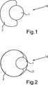
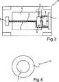
Zur Lösung dieser Aufgabe sieht die vorliegende Erfindung demnach eine Leitungsvorrichtung für ein Kraftfahrzeug mit einem elektrischen Leiter und einer Kühlleitung vor. Diese Leitungsvorrichtung zeichnet sich dadurch aus, dass die Kühlleitung im Querschnitt sichelförmig ausgebildet ist und eine Mantelfläche des elektrischen Leiters zu einem Anteil umfasst, oder die Kühlleitung und der elektrische Leiter konzentrisch ausgebildet sind. Dadurch kann dauerhaft eine Kühlung des elektrischen Leiters bereitgestellt werden, was zum Beispiel die Gefahr von Leitungsbränden reduzieren kann. Ferner kann durch diese passive Kühlungsmaßnahme die Ladeleistung des elektrischen Leiters erhöht werden und somit die Ladezeiten zum Aufladen der Batterie reduziert werden. Auch kann es möglich sein, eventuell elektrische Ladeleitungen mit geringeren Leitungsquerschnitten zu verwenden, was zusätzlichen Bauraum in dem Kraftfahrzeug schaffen kann. To solve this problem, the present invention therefore provides a conduit device for a motor vehicle with an electrical conductor and a cooling line. This line device is characterized in that the cooling line is formed sickle-shaped in cross-section and comprises a lateral surface of the electrical conductor to a proportion, or the cooling line and the electrical conductor are formed concentrically. As a result, a cooling of the electrical conductor can be permanently provided, which, for example, can reduce the risk of cable fires. Furthermore, by this passive cooling measure, the charging power of the electrical conductor can be increased and thus the charging times for charging the battery can be reduced. It may also be possible to possibly use electrical charging lines with smaller cross-sections, which can create additional space in the motor vehicle.
Eine besonders vorteilhafte Variante dieser Erfindung sieht eine Leitungsvorrichtung vor, wobei der elektrische Leiter und die Kühlleitung von einer Ummantelung zu einem Gesamtkabel umschlossen sind. In dieser Variante kann durch die Ummantelung die Kontaktierung von der Kühlleitung und dem elektrischen Leiter zusätzlich verstärkt werden. Die Kühlleitung sowie der elektrische Leiter bilden damit eine Einheit und sind dadurch besser miteinander verbunden. Damit kann eine Kühlung des elektrischen Leiters besser sichergestellt werden, weil durch die Ummantelung die Kühlleitung und die elektrische Leitung ein Gesamtkabel bilden und beim Verlegen des Gesamtkabels die Kühlleitung nicht vergessen werden kann.A particularly advantageous variant of this invention provides a line device, wherein the electrical conductor and the cooling line are enclosed by a sheath to a total cable. In this variant, the contacting of the cooling line and the electrical conductor can be additionally reinforced by the sheath. The cooling line and the electrical conductor thus form a unit and are thus better connected to each other. In order for a cooling of the electrical conductor can be better ensured because the cooling line and the electrical line form a total cable through the jacket and the cooling line can not be forgotten when laying the entire cable.
Eine weitere Option der vorliegenden Erfindung sieht eine Leitungsvorrichtung vor, wobei der elektrische Leiter als Hochvoltleitung oder als Ladestromleitung ausgeführt ist. Bei Hochvoltleitungen beziehungsweise Ladestromleitungen treten häufig hohe Spannungen und/oder hohe Stromstärken auf. Dies bedeutet auch eine erhöhte Wärmeentwicklung aufgrund der höheren Verlustleistung. Daher macht die erfindungsgemäße passive Kühlung bei Hochvoltleitungen oder Ladestromleitungen besonders viel Sinn.A further option of the present invention provides a line device, wherein the electrical conductor is designed as a high-voltage line or as a charging power line. In high-voltage lines or charging lines often high voltages and / or high currents occur. This also means increased heat development due to the higher power loss. Therefore, the passive cooling according to the invention makes a lot of sense in high-voltage lines or charging power lines.
Eine weitere vorteilhafte Variante der vorliegenden Erfindung sieht eine Leitungsvorrichtung vor, wobei in der Kühlleitung Wasser als Kühlmittel enthalten ist. Wasser ist umwelttechnisch gesehen meistens unbedenklich und kann daher fast immer ohne Weiteres eingesetzt werden. Außerdem weist Wasser im Vergleich zu vielen anderen Wärmeübertragungsflüssigkeiten eine relativ hohe Wärmekapazität auf. Dies bedeutet, dass Wasser bei gleicher Temperaturerhöhung mehr Energie aufnimmt als beispielsweise ein Thermo-Öl mit geringerer Wärmekapazität. Zudem ist Wasser leicht verfügbar und hat sich bereits in vielen Fällen erfolgreich als Wärmeübertragungsmedium bewährt.A further advantageous variant of the present invention provides a line device, wherein water is contained as coolant in the cooling line. From an environmental point of view, water is generally harmless and can therefore almost always be used without further ado. In addition, compared to many other heat transfer fluids, water has a relatively high heat capacity. This means that with the same increase in temperature, water absorbs more energy than, for example, a thermal oil with a lower heat capacity. In addition, water is readily available and has already proven successful in many cases as a heat transfer medium.
Weitere Vorteile, Merkmale und Einzelheiten der Erfindung ergeben sich aus der nachfolgenden Beschreibung bevorzugter Ausführungsbeispiele sowie anhand der Zeichnungen. Die vorstehend in der Beschreibung genannten Merkmale und Merkmalskombinationen sowie die nachfolgend in der Figurenbeschreibung genannten und/oder in den Figuren alleine gezeigten Merkmale und Merkmalskombinationen sind nicht nur in der jeweils angegebenen Kombination, sondern auch in anderen Kombinationen oder in Alleinstellung verwendbar, ohne den Rahmen der Erfindung zu verlassen.Further advantages, features and details of the invention will become apparent from the following description of preferred embodiments and from the drawings. The features and feature combinations mentioned above in the description as well as the features and feature combinations mentioned below in the description of the figures and / or in the figures alone can be used not only in the respectively specified combination but also in other combinations or in isolation, without the scope of To leave invention.
Dabei zeigen:Showing:
In
Dieses Gesamtkonstrukt kann in einem weiteren Beispiel als Mantelrohrsystem, wie in
Elektrische Hochvoltleitungen
Für die Simulationen wurden folgende Annahmen getroffen. Eine Temperaturänderung in der Kühlleitung
Mit diesen Annahmen wurden verschiedene Simulationen mit einer Simulationsdauer von 2 bis 3 Stunden durchgeführt. Dabei wurden unterschiedliche Hochvoltleitungen
Das Ergebnis der Simulationen gemäß vorstehender Tabelle zeigt, dass die Temperaturen an den Hochvoltleitungen
Die Hochvoltleitung
Es wurden auch Simulationen mit Umgebungstemperaturen von mehr als 20°C durchgeführt. Dabei zeigte sich, dass die maximale Oberflächentemperatur der Hochvoltleitung
Die Simulationen können somit dabei helfen, die Oberflächentemperatur des elektrischen Leiters
In
Es ist dabei besonders vorteilhaft, wenn bereits vorhandene Kühlschläuche, wie zum Beispiel für den On Board Lader, verwendet werden. Das heißt es müssen keine separate Kühlleitungen
Häufig ist die Kühlmitteltemperatur für Elektromotoren
Aufgrund des Siedepunkts von Wasser, der unter Normalbedingungen bei 100°C liegt, kann es sinnvoll sein, ein anderes Kühlmittel als Wasser zu verwenden. Es kann sinnvoll sein, andere Kühlmittel einzusetzen, welche auch über 100°C noch flüssig sind. Wird eine Kühlflüssigkeit gewählt, deren Siedepunkt so hoch ist, dass eine Verdampfung nicht zu erwarten ist, so kann auch bei Temperaturen über dem Siedepunkt von Wasser eine effiziente Kühlung bereitgestellt werden. Nichtsdestotrotz bleibt Wasser bzw. Wasser-Glykolgemisch ein effizientes, umweltfreundliches und relativ günstiges Kühlmedium.Due to the boiling point of water, which is under normal conditions at 100 ° C, it may be useful to use a coolant other than water. It may be useful to use other coolants, which are still liquid above 100 ° C. If a cooling liquid is selected whose boiling point is so high that evaporation is not to be expected, efficient cooling can be provided even at temperatures above the boiling point of water. Nevertheless, water or water-glycol mixture remains an efficient, environmentally friendly and relatively inexpensive cooling medium.
BezugszeichenlisteLIST OF REFERENCE NUMBERS
- 11
- elektrischer Leiterelectrical conductor
- 22
- Kühlleitungcooling line
- 33
- Ummantelungjacket
- 44
- Batteriebattery
- 55
- Ladeboxloading box
- 66
- Elektromotorelectric motor
- 77
- Kühlungcooling
- 88th
- Verteilerdistributor
- 99
- HochvoltleitungHigh-voltage line
- 1010
- Leitungsvorrichtungconducting device
- 1111
- Elektrofahrzeugelectric vehicle
ZITATE ENTHALTEN IN DER BESCHREIBUNG QUOTES INCLUDE IN THE DESCRIPTION
Diese Liste der vom Anmelder aufgeführten Dokumente wurde automatisiert erzeugt und ist ausschließlich zur besseren Information des Lesers aufgenommen. Die Liste ist nicht Bestandteil der deutschen Patent- bzw. Gebrauchsmusteranmeldung. Das DPMA übernimmt keinerlei Haftung für etwaige Fehler oder Auslassungen.This list of the documents listed by the applicant has been generated automatically and is included solely for the better information of the reader. The list is not part of the German patent or utility model application. The DPMA assumes no liability for any errors or omissions.
Zitierte PatentliteraturCited patent literature
- US 2015/0217654 A1[0006]US 2015/0217654 A1[0006]
- DE 112012003099 T5[0007]DE 112012003099 T5[0007]
Claims (5)
Translated fromGermanPriority Applications (1)
| Application Number | Priority Date | Filing Date | Title |
|---|---|---|---|
| DE102017004468.6ADE102017004468A1 (en) | 2017-05-10 | 2017-05-10 | Cooling of electrical charging power lines |
Applications Claiming Priority (1)
| Application Number | Priority Date | Filing Date | Title |
|---|---|---|---|
| DE102017004468.6ADE102017004468A1 (en) | 2017-05-10 | 2017-05-10 | Cooling of electrical charging power lines |
Publications (1)
| Publication Number | Publication Date |
|---|---|
| DE102017004468A1true DE102017004468A1 (en) | 2017-11-02 |
Family
ID=60081406
Family Applications (1)
| Application Number | Title | Priority Date | Filing Date |
|---|---|---|---|
| DE102017004468.6AWithdrawnDE102017004468A1 (en) | 2017-05-10 | 2017-05-10 | Cooling of electrical charging power lines |
Country Status (1)
| Country | Link |
|---|---|
| DE (1) | DE102017004468A1 (en) |
Cited By (2)
| Publication number | Priority date | Publication date | Assignee | Title |
|---|---|---|---|---|
| DE102017120725A1 (en)* | 2017-09-08 | 2019-03-14 | Lisa Dräxlmaier GmbH | HEATING DEVICE FOR AN ELECTRICAL LINE, EQUIPPED LINE ARRANGEMENT AND METHOD FOR HEATING AN ELECTRICAL LINE |
| DE102018215875A1 (en)* | 2018-09-18 | 2020-03-19 | Bayerische Motoren Werke Aktiengesellschaft | Charging string device for a battery of a motor vehicle |
Citations (2)
| Publication number | Priority date | Publication date | Assignee | Title |
|---|---|---|---|---|
| DE112012003099T5 (en) | 2011-07-25 | 2014-07-24 | Lightening Energy | Charging station for fast charging of an electric vehicle battery |
| US20150217654A1 (en) | 2014-02-05 | 2015-08-06 | Tesla Motors, Inc. | Cooling of charging cable |
- 2017
- 2017-05-10DEDE102017004468.6Apatent/DE102017004468A1/ennot_activeWithdrawn
Patent Citations (2)
| Publication number | Priority date | Publication date | Assignee | Title |
|---|---|---|---|---|
| DE112012003099T5 (en) | 2011-07-25 | 2014-07-24 | Lightening Energy | Charging station for fast charging of an electric vehicle battery |
| US20150217654A1 (en) | 2014-02-05 | 2015-08-06 | Tesla Motors, Inc. | Cooling of charging cable |
Cited By (3)
| Publication number | Priority date | Publication date | Assignee | Title |
|---|---|---|---|---|
| DE102017120725A1 (en)* | 2017-09-08 | 2019-03-14 | Lisa Dräxlmaier GmbH | HEATING DEVICE FOR AN ELECTRICAL LINE, EQUIPPED LINE ARRANGEMENT AND METHOD FOR HEATING AN ELECTRICAL LINE |
| DE102018215875A1 (en)* | 2018-09-18 | 2020-03-19 | Bayerische Motoren Werke Aktiengesellschaft | Charging string device for a battery of a motor vehicle |
| US11433773B2 (en) | 2018-09-18 | 2022-09-06 | Bayerische Motoren Werke Aktiengesellschaft | Charging harness unit for a battery of a motor vehicle |
Similar Documents
| Publication | Publication Date | Title |
|---|---|---|
| DE102017103268B4 (en) | Electrical conductor arrangement and motor vehicle | |
| EP3465699B1 (en) | Charging cable for transfer of energy, charging connector and charging station for supply of energy to an energy receiver | |
| EP3443566B1 (en) | Charging cable for transmitting electrical energy, charging plug and charging station for discharging electrical energy to a recipient of electrical energy | |
| EP3511952A2 (en) | Quick charging station with charging cable and temperature regulating device for the charging cable | |
| EP3649703B1 (en) | Charging cable system with cooling | |
| EP3628533A1 (en) | Liquid-cooled cable structure and method for cooling a cable construction | |
| DE102015221571A1 (en) | Device for cooling an electrical connector | |
| DE102016206300B4 (en) | CHARGING PLUG AND CHARGING STATION FOR DELIVERING ELECTRICAL ENERGY TO A RECEIVER OF ELECTRICAL ENERGY | |
| DE102011100389A1 (en) | Charging cable for transmitting electrical energy in energy storage device of e.g. electric vehicle, has current conductor and coolant guiding device that are arranged within cable sheath | |
| DE202011050446U1 (en) | Electrical connector element | |
| DE102014103909A1 (en) | Cooling circuit for a motor vehicle and use of an electrically non-conductive coolant | |
| DE102020120819A1 (en) | Cooled charging cable | |
| DE102017004468A1 (en) | Cooling of electrical charging power lines | |
| DE102020110199A1 (en) | Charging cable with ring-shaped protective elements and charging cable arrangement | |
| DE102017010274A1 (en) | Battery assembly for a vehicle | |
| WO2024193890A1 (en) | Cooled charging cable with cooling of passive line elements | |
| DE102022129995A1 (en) | Charging connectors for electric and hybrid vehicles | |
| DE102018120932A1 (en) | Cable section | |
| DE102021112928A1 (en) | Chassis and vehicle provided with such a chassis | |
| DE202017007498U1 (en) | Charging cable system with cooling | |
| DE102019127039A1 (en) | Battery module | |
| DE102013201530A1 (en) | Motor vehicle has vehicle electrical system that is provided with loads that are connected using supply line via power source, and ground connection that is formed by conductive connection | |
| DE102024115734B3 (en) | Cooled busbar and charging system | |
| DE102017217582A1 (en) | Arrangement, method and use for cooling an electric drive unit and aircraft with such an arrangement | |
| DE102020208965A1 (en) | Charging cable for an electric vehicle |
Legal Events
| Date | Code | Title | Description |
|---|---|---|---|
| R083 | Amendment of/additions to inventor(s) | ||
| R230 | Request for early publication | ||
| R119 | Application deemed withdrawn, or ip right lapsed, due to non-payment of renewal fee |