DE102016225153B4 - lighting unit - Google Patents
lighting unitDownload PDFInfo
- Publication number
- DE102016225153B4 DE102016225153B4DE102016225153.8ADE102016225153ADE102016225153B4DE 102016225153 B4DE102016225153 B4DE 102016225153B4DE 102016225153 ADE102016225153 ADE 102016225153ADE 102016225153 B4DE102016225153 B4DE 102016225153B4
- Authority
- DE
- Germany
- Prior art keywords
- light
- lighting unit
- light diffusion
- lichtumlenkfolie
- housing
- Prior art date
- Legal status (The legal status is an assumption and is not a legal conclusion. Google has not performed a legal analysis and makes no representation as to the accuracy of the status listed.)
- Expired - Fee Related
Links
- 238000009792diffusion processMethods0.000claimsabstractdescription38
- 239000011888foilSubstances0.000claimsdescription14
- 239000000463materialSubstances0.000claimsdescription8
- 239000000853adhesiveSubstances0.000claimsdescription7
- 239000006260foamSubstances0.000claimsdescription7
- 230000001070adhesive effectEffects0.000claimsdescription4
- 238000000149argon plasma sinteringMethods0.000claimsdescription3
- 239000011521glassSubstances0.000description8
- 238000005286illuminationMethods0.000description7
- 239000004033plasticSubstances0.000description5
- 229920003023plasticPolymers0.000description5
- 239000010408filmSubstances0.000description4
- 238000009434installationMethods0.000description3
- 230000003287optical effectEffects0.000description3
- 239000012788optical filmSubstances0.000description3
- 238000005516engineering processMethods0.000description1
- 239000000203mixtureSubstances0.000description1
- 229920003229poly(methyl methacrylate)Polymers0.000description1
- 239000004926polymethyl methacrylateSubstances0.000description1
Images


Classifications
- B—PERFORMING OPERATIONS; TRANSPORTING
- B60—VEHICLES IN GENERAL
- B60Q—ARRANGEMENT OF SIGNALLING OR LIGHTING DEVICES, THE MOUNTING OR SUPPORTING THEREOF OR CIRCUITS THEREFOR, FOR VEHICLES IN GENERAL
- B60Q1/00—Arrangement of optical signalling or lighting devices, the mounting or supporting thereof or circuits therefor
- B60Q1/26—Arrangement of optical signalling or lighting devices, the mounting or supporting thereof or circuits therefor the devices being primarily intended to indicate the vehicle, or parts thereof, or to give signals, to other traffic
- B60Q1/2661—Arrangement of optical signalling or lighting devices, the mounting or supporting thereof or circuits therefor the devices being primarily intended to indicate the vehicle, or parts thereof, or to give signals, to other traffic mounted on parts having other functions
- B60Q1/2665—Arrangement of optical signalling or lighting devices, the mounting or supporting thereof or circuits therefor the devices being primarily intended to indicate the vehicle, or parts thereof, or to give signals, to other traffic mounted on parts having other functions on rear-view mirrors
- B—PERFORMING OPERATIONS; TRANSPORTING
- B60—VEHICLES IN GENERAL
- B60Q—ARRANGEMENT OF SIGNALLING OR LIGHTING DEVICES, THE MOUNTING OR SUPPORTING THEREOF OR CIRCUITS THEREFOR, FOR VEHICLES IN GENERAL
- B60Q1/00—Arrangement of optical signalling or lighting devices, the mounting or supporting thereof or circuits therefor
- B60Q1/26—Arrangement of optical signalling or lighting devices, the mounting or supporting thereof or circuits therefor the devices being primarily intended to indicate the vehicle, or parts thereof, or to give signals, to other traffic
- B60Q1/46—Arrangement of optical signalling or lighting devices, the mounting or supporting thereof or circuits therefor the devices being primarily intended to indicate the vehicle, or parts thereof, or to give signals, to other traffic for giving flashing caution signals during drive, other than signalling change of direction, e.g. flashing the headlights or hazard lights
- B—PERFORMING OPERATIONS; TRANSPORTING
- B60—VEHICLES IN GENERAL
- B60Q—ARRANGEMENT OF SIGNALLING OR LIGHTING DEVICES, THE MOUNTING OR SUPPORTING THEREOF OR CIRCUITS THEREFOR, FOR VEHICLES IN GENERAL
- B60Q9/00—Arrangement or adaptation of signal devices not provided for in one of main groups B60Q1/00 - B60Q7/00, e.g. haptic signalling
- B60Q9/008—Arrangement or adaptation of signal devices not provided for in one of main groups B60Q1/00 - B60Q7/00, e.g. haptic signalling for anti-collision purposes
- B—PERFORMING OPERATIONS; TRANSPORTING
- B60—VEHICLES IN GENERAL
- B60R—VEHICLES, VEHICLE FITTINGS, OR VEHICLE PARTS, NOT OTHERWISE PROVIDED FOR
- B60R1/00—Optical viewing arrangements; Real-time viewing arrangements for drivers or passengers using optical image capturing systems, e.g. cameras or video systems specially adapted for use in or on vehicles
- B60R1/02—Rear-view mirror arrangements
- B60R1/06—Rear-view mirror arrangements mounted on vehicle exterior
- B—PERFORMING OPERATIONS; TRANSPORTING
- B60—VEHICLES IN GENERAL
- B60R—VEHICLES, VEHICLE FITTINGS, OR VEHICLE PARTS, NOT OTHERWISE PROVIDED FOR
- B60R1/00—Optical viewing arrangements; Real-time viewing arrangements for drivers or passengers using optical image capturing systems, e.g. cameras or video systems specially adapted for use in or on vehicles
- B60R1/12—Mirror assemblies combined with other articles, e.g. clocks
- B60R1/1207—Mirror assemblies combined with other articles, e.g. clocks with lamps; with turn indicators
- F—MECHANICAL ENGINEERING; LIGHTING; HEATING; WEAPONS; BLASTING
- F21—LIGHTING
- F21S—NON-PORTABLE LIGHTING DEVICES; SYSTEMS THEREOF; VEHICLE LIGHTING DEVICES SPECIALLY ADAPTED FOR VEHICLE EXTERIORS
- F21S41/00—Illuminating devices specially adapted for vehicle exteriors, e.g. headlamps
- F21S41/20—Illuminating devices specially adapted for vehicle exteriors, e.g. headlamps characterised by refractors, transparent cover plates, light guides or filters
- F21S41/285—Refractors, transparent cover plates, light guides or filters not provided in groups F21S41/24 - F21S41/2805
- F—MECHANICAL ENGINEERING; LIGHTING; HEATING; WEAPONS; BLASTING
- F21—LIGHTING
- F21S—NON-PORTABLE LIGHTING DEVICES; SYSTEMS THEREOF; VEHICLE LIGHTING DEVICES SPECIALLY ADAPTED FOR VEHICLE EXTERIORS
- F21S43/00—Signalling devices specially adapted for vehicle exteriors, e.g. brake lamps, direction indicator lights or reversing lights
- F21S43/10—Signalling devices specially adapted for vehicle exteriors, e.g. brake lamps, direction indicator lights or reversing lights characterised by the light source
- F21S43/13—Signalling devices specially adapted for vehicle exteriors, e.g. brake lamps, direction indicator lights or reversing lights characterised by the light source characterised by the type of light source
- F21S43/14—Light emitting diodes [LED]
- F—MECHANICAL ENGINEERING; LIGHTING; HEATING; WEAPONS; BLASTING
- F21—LIGHTING
- F21S—NON-PORTABLE LIGHTING DEVICES; SYSTEMS THEREOF; VEHICLE LIGHTING DEVICES SPECIALLY ADAPTED FOR VEHICLE EXTERIORS
- F21S43/00—Signalling devices specially adapted for vehicle exteriors, e.g. brake lamps, direction indicator lights or reversing lights
- F21S43/10—Signalling devices specially adapted for vehicle exteriors, e.g. brake lamps, direction indicator lights or reversing lights characterised by the light source
- F21S43/19—Attachment of light sources or lamp holders
- F21S43/195—Details of lamp holders, terminals or connectors
- F—MECHANICAL ENGINEERING; LIGHTING; HEATING; WEAPONS; BLASTING
- F21—LIGHTING
- F21S—NON-PORTABLE LIGHTING DEVICES; SYSTEMS THEREOF; VEHICLE LIGHTING DEVICES SPECIALLY ADAPTED FOR VEHICLE EXTERIORS
- F21S43/00—Signalling devices specially adapted for vehicle exteriors, e.g. brake lamps, direction indicator lights or reversing lights
- F21S43/20—Signalling devices specially adapted for vehicle exteriors, e.g. brake lamps, direction indicator lights or reversing lights characterised by refractors, transparent cover plates, light guides or filters
- F21S43/26—Refractors, transparent cover plates, light guides or filters not provided in groups F21S43/235 - F21S43/255
- F—MECHANICAL ENGINEERING; LIGHTING; HEATING; WEAPONS; BLASTING
- F21—LIGHTING
- F21S—NON-PORTABLE LIGHTING DEVICES; SYSTEMS THEREOF; VEHICLE LIGHTING DEVICES SPECIALLY ADAPTED FOR VEHICLE EXTERIORS
- F21S43/00—Signalling devices specially adapted for vehicle exteriors, e.g. brake lamps, direction indicator lights or reversing lights
- F21S43/20—Signalling devices specially adapted for vehicle exteriors, e.g. brake lamps, direction indicator lights or reversing lights characterised by refractors, transparent cover plates, light guides or filters
- F21S43/27—Attachment thereof
- F—MECHANICAL ENGINEERING; LIGHTING; HEATING; WEAPONS; BLASTING
- F21—LIGHTING
- F21V—FUNCTIONAL FEATURES OR DETAILS OF LIGHTING DEVICES OR SYSTEMS THEREOF; STRUCTURAL COMBINATIONS OF LIGHTING DEVICES WITH OTHER ARTICLES, NOT OTHERWISE PROVIDED FOR
- F21V17/00—Fastening of component parts of lighting devices, e.g. shades, globes, refractors, reflectors, filters, screens, grids or protective cages
- F21V17/10—Fastening of component parts of lighting devices, e.g. shades, globes, refractors, reflectors, filters, screens, grids or protective cages characterised by specific fastening means or way of fastening
- F21V17/101—Fastening of component parts of lighting devices, e.g. shades, globes, refractors, reflectors, filters, screens, grids or protective cages characterised by specific fastening means or way of fastening permanently, e.g. welding, gluing or riveting
- B—PERFORMING OPERATIONS; TRANSPORTING
- B60—VEHICLES IN GENERAL
- B60Q—ARRANGEMENT OF SIGNALLING OR LIGHTING DEVICES, THE MOUNTING OR SUPPORTING THEREOF OR CIRCUITS THEREFOR, FOR VEHICLES IN GENERAL
- B60Q2400/00—Special features or arrangements of exterior signal lamps for vehicles
- B60Q2400/40—Welcome lights, i.e. specific or existing exterior lamps to assist leaving or approaching the vehicle
- F—MECHANICAL ENGINEERING; LIGHTING; HEATING; WEAPONS; BLASTING
- F21—LIGHTING
- F21Y—INDEXING SCHEME ASSOCIATED WITH SUBCLASSES F21K, F21L, F21S and F21V, RELATING TO THE FORM OR THE KIND OF THE LIGHT SOURCES OR OF THE COLOUR OF THE LIGHT EMITTED
- F21Y2115/00—Light-generating elements of semiconductor light sources
- F21Y2115/10—Light-emitting diodes [LED]
Landscapes
- Engineering & Computer Science (AREA)
- Mechanical Engineering (AREA)
- General Engineering & Computer Science (AREA)
- Multimedia (AREA)
- Human Computer Interaction (AREA)
- Physics & Mathematics (AREA)
- Microelectronics & Electronic Packaging (AREA)
- Optics & Photonics (AREA)
- Lighting Device Outwards From Vehicle And Optical Signal (AREA)
- Non-Portable Lighting Devices Or Systems Thereof (AREA)
Abstract
Translated fromGermanDescription
Translated fromGermanDie Erfindung betrifft eine Beleuchtungseinheit für die Anwendung im automotiven Bereich. Die erfindungsgemäße Beleuchtungseinheit fügt sich harmonisch in die Kontur des Fahrzeugs ein.The invention relates to a lighting unit for use in the automotive sector. The lighting unit according to the invention blends harmoniously into the contour of the vehicle.
Stand der TechnikState of the art
Aus dem Stand der Technik ist eine Vielzahl von Beleuchtungskörper im Fahrzeug bekannt. Sowohl im Innenraumbereich als auch an der Außenkontur des Fahrzeugs werden unterschiedliche Beleuchtungseinheiten angebracht, die unterschiedlichen Funktionen erfüllen.From the prior art, a plurality of lighting fixtures in the vehicle is known. Both in the interior and on the outer contour of the vehicle different lighting units are mounted, which fulfill different functions.
Im Innenraumbereich handelt es sich um Beleuchtungen für Instrumente oder bestimmte Fahrzeugbereiche, um Ausleuchtungen zur Kennzeichnung von Bedienelementen oder für Beleuchtungen zum Lesen oder zur Ambientebeleuchtung bereitzustellen. Um eine angenehme Umgebung zu schaffen, werden Bereiche wie der Fußraum, die Armablage an den Fahrzeugtüren, Bedienelement, Innenspiegel oder Dachmodule mindestens beim Ein- und Austeigen beleuchtet.The interior area is instrument lighting or certain areas of the vehicle to provide illumination to identify controls or illumination for reading or ambient lighting. In order to create a pleasant environment, areas such as the footwell, the armrest on the vehicle doors, control element, interior mirror or roof modules are illuminated at least when entering and leaving.
Im Außenbereich des Fahrzeugs dient Beleuchtung zur Kennzeichnung als Positionslicht, als Front-oder Heckbeleuchtung oder als blinkende Anzeige für Spurwechsel oder als Gefahranzeige für den Fahrer.In the exterior of the vehicle, lighting is used to indicate position light, front or rear lighting, or a flashing display for lane change or as a hazard warning to the driver.
Sowohl innen als auch außen müssen die Beleuchtungen bestimmten Anforderungen genügen. Hier ist zunächst die Zulassungsfähigkeit zu beachten, die beispielsweise Leuchtdichte und Blinkwiederholraten von Blinkern festlegt. Auch die auszuleuchtenden Raumbereiche in der Umgebung des Fahrzeugs sind durch Regulierungen bestimmt. Neben den Zulassungsauflagen bestimmt die Funktion und das Design das Aussehen der Beleuchtung.Both inside and outside the lighting must meet certain requirements. First of all, the approval capability must be taken into account, which determines, for example, the luminance and blink repetition rates of turn signals. The areas to be illuminated in the vicinity of the vehicle are also determined by regulations. In addition to the approval requirements, the function and design determine the appearance of the lighting.
Ein wichtiger Parameter im Stand der Technik ist dabei, dass die Beleuchtung verborgen angebracht wird. Das bedeutet, dass die Abdeckscheibe, die die Beleuchtungseinheit nach außen hin abschließt, im Farbton an die Umgebung angepasst wird oder dunkel eingefärbt ist, um nicht aufzufallen.An important parameter in the prior art is that the lighting is hidden. This means that the cover, which closes the lighting unit to the outside, is adjusted in color to the environment or dark color, so as not to attract attention.
Zudem soll die Abdeckscheibe eine freie Sicht auf die technischen Bauteile im Innern der Beleuchtungseinheit verhindern.In addition, the cover should prevent a clear view of the technical components inside the lighting unit.
Je nach Einsatzort und Einsatzzweck soll das Licht einer oder mehreren Lichtquellen die Abdeckscheibe harmonisch ausleuchten und einen diffusen Lichteindruck hinterlassen. Alternativ dazu wird auch eine definierte Ausleuchtung der Umgebung des Fahrzeuges oder ein auf ein Bauteil des Interieur gerichteter Lichtstrahl gewünscht.Depending on the location and purpose of use, the light of one or more light sources should illuminate the cover harmoniously and leave a diffuse light impression. Alternatively, a defined illumination of the environment of the vehicle or directed to a component of the interior light beam is desired.
Im Stand der Technik wird in der
Aus der
Die
Aus der US 2016 / 0 078 768 A1 ist eine Beleuchtungseinheit bekannt, die als Warnanzeige im Fahrzeugaußenspiegel eingesetzt wird. Die Beleuchtungseinheit umfasst ein Gehäuse und ist hinter dem Spiegelglas angeordnet. Das Gehäuse wird über die Spiegelglasscheibe verschlossen.From US 2016/0707868 A1 a lighting unit is known, which is used as a warning display in the vehicle outside mirror. The lighting unit comprises a housing and is arranged behind the mirror glass. The housing is closed via the mirror glass pane.
Eine weitere Beleuchtungseinheit ist aus der US 2004 / 0 080 958 A1 bekannt. Diese bekannte Beleuchtungseinheit umfasst kein eigenes Gehäuse sondern ist in dem Spiegelgehäuse hinter dem Spiegelglas aufgenommen. Eine erste Lichtquelle strahlt dabei Licht durch eine im Spiegelgehäuse angeordnete transparente Lichtscheibe, die das Gehäuse verschließt.Another illumination unit is known from US 2004/0 080 958 A1. This known lighting unit does not have its own housing but is accommodated in the mirror housing behind the mirror glass. A first light source emits light through a transparent lens arranged in the mirror housing, which closes the housing.
Aus der
Es ist daher Ziel der vorliegenden Anmeldung eine Beleuchtungseinheit zu schaffen, die das Licht in gewünschter Form emittiert, wobei keine aufwendigen und kostenintensiven Vorkehrungen zu treffen sind.It is therefore an object of the present application to provide a lighting unit that illuminates the light emitted in the desired form, with no costly and expensive arrangements are to be made.
Die Lösung der Aufgabe erfolgt mit einer Beleuchtungseinheit mit einem Gehäuse, umfassend mindestens eine Lichtquelle mit einer Hauptlichtausbreitung, die ihr Licht durch ein Lichtdiffusionsbauteil und eine Lichtumlenkfolie abstrahlt, wobei die Lichtumlenkfolie an die Kontur eines Fahrzeugbauteils angepasst ist, wobei die mindestens eine Lichtumlenkfolie eine Mikrostruktur auf der der Lichtquelle abgewandten Außenseite aufweist, die das Licht in eine vom Einfallswinkel abweichende Richtung ablenkt, und wobei das Lichtdiffusionsbauteil als Lichtdiffusionsfolie mit einer in Richtung der Hauptlichtausbreitung (7) liegenden Lichtdiffusionsschicht ausgeführt ist, und wobei die Lichtumlenkfolie das Gehäuse verschließt.The object is achieved with a lighting unit having a housing, comprising at least one light source with a main light propagation, which emits its light through a light diffusion component and a Lichtumlenkfolie, wherein the Lichtumlenkfolie adapted to the contour of a vehicle component, wherein the at least one Lichtumlenkfolie on a microstructure the outer side facing away from the light source, which deflects the light in a direction deviating from the angle of incidence, and wherein the light diffusion component is designed as a light diffusion foil with a light diffusion layer lying in the direction of the main light propagation (7), and wherein the light deflection foil closes the housing.
Durch das Weglassen einer Abdeckscheibe ist der Aufbau der Beleuchtungseinheit vereinfacht. Zudem wird die Mikrostruktur außen aufgebracht und so der Lichtweg nach der Ablenkung direkter auf den Fahrer abgelenkt.By omitting a cover, the structure of the lighting unit is simplified. In addition, the microstructure is applied to the outside and so deflected the light path after the deflection directly to the driver.
Es ist von Vorteil, dass die Lichtumlenkfolie eine prismatische Mikrostruktur aufweist, die eine einfache Ablenkung des Lichts ermöglicht.It is advantageous that the Lichtumlenkfolie has a prismatic microstructure, which allows easy deflection of the light.
Vorteilhafterweise ist die Lichtumlenkfolie Teil der Fahrzeugkontur.Advantageously, the Lichtumlenkfolie part of the vehicle contour.
Es ist von Vorteil, wenn das Lichtdiffusionsbauteil eine Lichtdiffusionsfolie ist, die ein Lichtdiffusionselement verschließt, das Öffnungen für die Leuchtmittel besitzt und innerhalb des Gehäuses angeordnet ist.It is advantageous if the light diffusion component is a light diffusion foil which closes a light diffusion element which has openings for the light sources and is arranged inside the housing.
Weiterhin ist es vorteilhaft, dass die Lichtdiffusionsfolie einseitig oder beidseitig mit einer Lichtdiffusionsschicht versehen ist oder das Material der Lichtdiffusionsfolie selbst lichtstreuende Eigenschaften besitzt.Furthermore, it is advantageous that the light diffusion foil is provided on one or both sides with a light diffusion layer or the material of the light diffusion foil itself has light-scattering properties.
Eine weitere vorteilhafte Ausgestaltung wird erreicht, wenn das Lichtdiffusionsbauteil eine in der Lichtumlenkfolie auf der Innenseite angebrachte Lichtdiffusionsschicht ist.A further advantageous embodiment is achieved if the light diffusion component is a light diffusion layer mounted on the inside in the light deflection film.
Eine weitere Ausgestaltung weist zwei oder mehrere Lichtumlenkfolien auf, die miteinander über weitere doppelt klebende Schäume gekoppelt sind.A further embodiment has two or more Lichtumlenkfolien coupled to each other via further double-adhesive foams.
Es ist von Vorteil, dass die Lichtumlenkfolie das Gehäuse mit einem am Rand des Gehäuses aufgebrachten doppelseitig klebenden Schaum verschließt.It is advantageous that the Lichtumlenkfolie closes the housing with a applied on the edge of the housing double-sided adhesive foam.
Die Beleuchtungseinheit ist als Warnanzeige im Außenspiegel verbaut.The lighting unit is installed as a warning indicator in the exterior mirror.
Figurenlistelist of figures
Es zeigen:
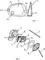
1 einen Außenspiegel mit Warnanzeige2 eine erfindungsgemäße Beleuchtungseinheit3 Details der Ausführungsform nach2 4 eine alternative Ausführungsform,5 ein Detail der Ausführung nach4 .6 einen Ausführungsform mit mehrere Folien.
1 an exterior mirror with warning indicator2 a lighting unit according to the invention3 Details of the embodiment according to2 4 an alternative embodiment,5 a detail of theexecution 4 ,6 an embodiment with multiple slides.
Die erfindungsgemäßen Beleuchtungseinheiten leuchten je nach Funktion als harmonisch beleuchtete Lichtbereiche auf. Eine Warnanzeige eines Fahrerassistenzsystems ist an der Position
Soll das Licht der Beleuchtungseinheit gerichtet ausgestrahlt werden, müssen Maßnahmen vorgenommen werden, die zu einer Ablenkung der ausgesendeten Lichtstrahlen führen.If the light of the lighting unit to be emitted in a targeted manner, measures must be taken that lead to a deflection of the emitted light beams.
An der Einbauposition
Eine Lichtdiffusionsfolie
Diese Lichtdiffusionsfolie kann einseitig oder beidseitig mit einer Lichtdiffusionsschicht versehen sein oder das Material der Lichtdiffusionsfolie selbst besitzt lichtstreuende Eigenschaften.This light diffusion foil can be provided on one or both sides with a light diffusion layer or the material of the light diffusion foil itself has light-scattering properties.
Auf dem Rand
Die Lichtumlenkfolie
Der elektrische Anschluss wird über einen Stecker
Prismatische optische Filme sind beispielsweise aus der
Durch die geringe Dicke der Lichtumlenkfolie stört er die optischen Eigenschaften der Beleuchtungseinheit nur sehr wenig. Die Struktur des Films ist vom Auge nicht mehr auflösbar.Due to the small thickness of the Lichtumlenkfolie he disturbs the optical properties of the lighting unit only very little. The structure of the film is no longer resolvable by the eye.
Das Licht der LEDs wird diffus gestreut und trifft auf die flache, unstrukturierte Innenseite
In
Claims (11)
Translated fromGermanPriority Applications (4)
| Application Number | Priority Date | Filing Date | Title |
|---|---|---|---|
| DE102016225153.8ADE102016225153B4 (en) | 2016-12-15 | 2016-12-15 | lighting unit |
| EP17203657.6AEP3336416B1 (en) | 2016-12-15 | 2017-11-24 | Illumination unit |
| US15/839,168US10391932B2 (en) | 2016-12-15 | 2017-12-12 | Illumination unit |
| CN201711343676.0ACN108224351B (en) | 2016-12-15 | 2017-12-14 | Lighting unit |
Applications Claiming Priority (1)
| Application Number | Priority Date | Filing Date | Title |
|---|---|---|---|
| DE102016225153.8ADE102016225153B4 (en) | 2016-12-15 | 2016-12-15 | lighting unit |
Publications (2)
| Publication Number | Publication Date |
|---|---|
| DE102016225153A1 DE102016225153A1 (en) | 2018-06-21 |
| DE102016225153B4true DE102016225153B4 (en) | 2018-07-12 |
Family
ID=60480196
Family Applications (1)
| Application Number | Title | Priority Date | Filing Date |
|---|---|---|---|
| DE102016225153.8AExpired - Fee RelatedDE102016225153B4 (en) | 2016-12-15 | 2016-12-15 | lighting unit |
Country Status (4)
| Country | Link |
|---|---|
| US (1) | US10391932B2 (en) |
| EP (1) | EP3336416B1 (en) |
| CN (1) | CN108224351B (en) |
| DE (1) | DE102016225153B4 (en) |
Families Citing this family (4)
| Publication number | Priority date | Publication date | Assignee | Title |
|---|---|---|---|---|
| CN210161982U (en)* | 2019-05-09 | 2020-03-20 | 麦格纳(太仓)汽车科技有限公司 | Lane-changing blind area warning lamp |
| FR3105345B1 (en)* | 2019-12-20 | 2022-10-14 | Valeo Vision Belgique | Automotive lighting device |
| CN216268972U (en)* | 2021-06-03 | 2022-04-12 | 江苏海华汽车部件有限公司 | Rearview mirror with RGB warning light |
| CN115447489A (en)* | 2022-08-31 | 2022-12-09 | 蔚来汽车科技(安徽)有限公司 | Rearview mirror and vehicle with same |
Citations (7)
| Publication number | Priority date | Publication date | Assignee | Title |
|---|---|---|---|---|
| EP0584547A1 (en) | 1992-07-24 | 1994-03-02 | MAGNETI MARELLI S.p.A. | Lighting device, in particular for use on motor vehicles |
| US5788357A (en) | 1996-08-28 | 1998-08-04 | K. W. Muth Company, Inc. | Mirror assembly |
| US20040080958A1 (en)* | 2002-10-29 | 2004-04-29 | Bukosky Allen A. | Signaling assembly |
| US7293901B2 (en) | 2004-03-09 | 2007-11-13 | Gentex Corporation | Optics for controlling the direction of light rays and assemblies incorporating the optics |
| US7763331B2 (en) | 2004-06-17 | 2010-07-27 | 3M Innovative Properties Company | Optical film assembly and display device |
| EP2500629A1 (en) | 2011-03-15 | 2012-09-19 | SMR Patents S.à.r.l. | Micro optics in lighting units |
| US20160078768A1 (en)* | 2014-09-11 | 2016-03-17 | Magna Mirrors Of America, Inc. | Exterior mirror with blind zone indicator |
Family Cites Families (18)
| Publication number | Priority date | Publication date | Assignee | Title |
|---|---|---|---|---|
| US6352359B1 (en)* | 1998-08-25 | 2002-03-05 | Physical Optics Corporation | Vehicle light assembly including a diffuser surface structure |
| KR20020010125A (en)* | 1999-03-15 | 2002-02-02 | 프레데릭 티. 바우어 | Indicators and illuminators using a semiconductor radiation emitter package |
| US7581859B2 (en)* | 2005-09-14 | 2009-09-01 | Donnelly Corp. | Display device for exterior rearview mirror |
| US8708982B2 (en)* | 2005-05-04 | 2014-04-29 | Edward D. Lin | Wound protection and therapy system |
| TWI274683B (en)* | 2006-05-19 | 2007-03-01 | Ind Tech Res Inst | Optical film for automobiles |
| JP2008074294A (en)* | 2006-09-22 | 2008-04-03 | Honda Motor Co Ltd | Infrared light reflector and two-wheeled vehicle and helmet with infrared light reflector |
| US7944371B2 (en)* | 2007-11-05 | 2011-05-17 | Magna Mirrors Of America, Inc. | Exterior mirror with indicator |
| WO2011050982A1 (en)* | 2009-10-29 | 2011-05-05 | Arno Martin Sauer | Plate for producing an led-illuminated sign |
| EP2481978B1 (en)* | 2011-01-28 | 2015-04-08 | SMR Patents S.à.r.l. | Rear view mirror comprising a hollow light guide |
| EP2675659A4 (en)* | 2011-02-14 | 2014-01-08 | Gentex Corp | Low profile optical lighting assembly for use in outside vehicle mirror and method of forming same |
| US9321395B2 (en)* | 2013-04-26 | 2016-04-26 | Ford Global Technologies, Llc | Vehicle puddle lamp assembly generating animated image and method |
| US9815409B2 (en)* | 2013-05-09 | 2017-11-14 | Magna Mirrors Of America, Inc. | Rearview vision system for vehicle |
| JP5920612B2 (en)* | 2013-10-24 | 2016-05-18 | フィリップス ライティング ホールディング ビー ヴィ | Optical structure having two or more microstructured films |
| CN203671513U (en)* | 2013-12-10 | 2014-06-25 | 裕盛工业股份有限公司 | Third brake light socket |
| JP5991498B2 (en)* | 2014-07-08 | 2016-09-14 | パナソニックIpマネジメント株式会社 | Myoelectric potential measuring device and myoelectric potential measuring method |
| US10609473B2 (en)* | 2014-09-30 | 2020-03-31 | Apple Inc. | Audio driver and power supply unit architecture |
| CN205239337U (en)* | 2015-12-19 | 2016-05-18 | 周晓华 | Take automobile rearview mirror of forward sight function |
| US20180288848A1 (en)* | 2017-03-28 | 2018-10-04 | GM Global Technology Operations LLC | Vehicle imaging systems and methods for lighting diagnosis |
- 2016
- 2016-12-15DEDE102016225153.8Apatent/DE102016225153B4/ennot_activeExpired - Fee Related
- 2017
- 2017-11-24EPEP17203657.6Apatent/EP3336416B1/enactiveActive
- 2017-12-12USUS15/839,168patent/US10391932B2/enactiveActive
- 2017-12-14CNCN201711343676.0Apatent/CN108224351B/enactiveActive
Patent Citations (7)
| Publication number | Priority date | Publication date | Assignee | Title |
|---|---|---|---|---|
| EP0584547A1 (en) | 1992-07-24 | 1994-03-02 | MAGNETI MARELLI S.p.A. | Lighting device, in particular for use on motor vehicles |
| US5788357A (en) | 1996-08-28 | 1998-08-04 | K. W. Muth Company, Inc. | Mirror assembly |
| US20040080958A1 (en)* | 2002-10-29 | 2004-04-29 | Bukosky Allen A. | Signaling assembly |
| US7293901B2 (en) | 2004-03-09 | 2007-11-13 | Gentex Corporation | Optics for controlling the direction of light rays and assemblies incorporating the optics |
| US7763331B2 (en) | 2004-06-17 | 2010-07-27 | 3M Innovative Properties Company | Optical film assembly and display device |
| EP2500629A1 (en) | 2011-03-15 | 2012-09-19 | SMR Patents S.à.r.l. | Micro optics in lighting units |
| US20160078768A1 (en)* | 2014-09-11 | 2016-03-17 | Magna Mirrors Of America, Inc. | Exterior mirror with blind zone indicator |
Also Published As
| Publication number | Publication date |
|---|---|
| US20180170249A1 (en) | 2018-06-21 |
| CN108224351B (en) | 2021-09-14 |
| US10391932B2 (en) | 2019-08-27 |
| CN108224351A (en) | 2018-06-29 |
| EP3336416B1 (en) | 2020-11-04 |
| EP3336416A1 (en) | 2018-06-20 |
| DE102016225153A1 (en) | 2018-06-21 |
Similar Documents
| Publication | Publication Date | Title |
|---|---|---|
| DE10123263B4 (en) | Light guide system for the interior of a motor vehicle | |
| DE102016009660B4 (en) | Illuminated trim | |
| DE102016225153B4 (en) | lighting unit | |
| DE102016007709B4 (en) | automotive trim part | |
| DE102006048323A1 (en) | External rear view mirror for motor vehicles, forms parts of mirror body and mirror head housings from at least two plastic films of different light permeabilities | |
| EP1848918B1 (en) | Illumination device | |
| DE102007048841A1 (en) | Door mirror with direction change indicator light | |
| DE102018002721B4 (en) | Lighting device for a vehicle | |
| DE102014006567B4 (en) | Backlit interior component | |
| DE102018001679A1 (en) | Exit light and exit light with logo | |
| WO2004014694A1 (en) | Lights for motor vehicles | |
| DE102004050600A1 (en) | Vehicle lighting unit for an opening region such as a door or boot has light field with many adjacent regions of different brightness | |
| DE102008025256A1 (en) | Interior fitting component i.e. glove box, for motor vehicle, has lamp emitting light that is guided on light emitting surface, where light in light radiating position is radiated to surface in direction of interior fitting parts | |
| EP1737701A1 (en) | Exterior rearview mirror for vehicles, especially for motor vehicles | |
| DE10129953A1 (en) | Light for vehicle interior has largest light component of light radiated by light conductor incident in main radiation direction first on reflector and from there to light panel | |
| DE102018004528B4 (en) | Vehicle lighting device with an elongated light guide and a cover | |
| DE202016103426U1 (en) | Motor vehicle headlamps | |
| EP2500629B1 (en) | Rearview mirror for a vehicle with lighting units with micro-optics | |
| EP2777988A1 (en) | Lighting device with a translucent illumination panel | |
| DE102012005481A1 (en) | Light fixture for use in passenger compartment of mass transportation unit, has transitional light element, which is arranged between light emitting surface of lighting element and surrounding surface of light fixture | |
| DE102015104572A1 (en) | Lighting device for aircraft interiors | |
| EP3414129B1 (en) | Lighting module of a vehicle | |
| DE102004007555B4 (en) | Interior light with high transparency and translucence, especially for vehicles with glass roof | |
| DE102014009199B4 (en) | Mounting element for installation in a panel of a vehicle | |
| DE10250675A1 (en) | Display unit, especially for motor vehicles, has illumination element with diffusing coating that is joined to smoked glass coating over their areas |
Legal Events
| Date | Code | Title | Description |
|---|---|---|---|
| R012 | Request for examination validly filed | ||
| R082 | Change of representative | Representative=s name:RAUSCH, GABRIELE, DIPL.-PHYS. DR.RER.NAT., DE | |
| R016 | Response to examination communication | ||
| R016 | Response to examination communication | ||
| R018 | Grant decision by examination section/examining division | ||
| R020 | Patent grant now final | ||
| R119 | Application deemed withdrawn, or ip right lapsed, due to non-payment of renewal fee |