DE102016218852A1 - Detection of objects from images of a camera - Google Patents
Detection of objects from images of a cameraDownload PDFInfo
- Publication number
- DE102016218852A1 DE102016218852A1DE102016218852.6ADE102016218852ADE102016218852A1DE 102016218852 A1DE102016218852 A1DE 102016218852A1DE 102016218852 ADE102016218852 ADE 102016218852ADE 102016218852 A1DE102016218852 A1DE 102016218852A1
- Authority
- DE
- Germany
- Prior art keywords
- corresponding features
- images
- homography
- levels
- objects
- Prior art date
- Legal status (The legal status is an assumption and is not a legal conclusion. Google has not performed a legal analysis and makes no representation as to the accuracy of the status listed.)
- Withdrawn
Links
Images


Classifications
- G—PHYSICS
- G06—COMPUTING OR CALCULATING; COUNTING
- G06V—IMAGE OR VIDEO RECOGNITION OR UNDERSTANDING
- G06V20/00—Scenes; Scene-specific elements
- G06V20/50—Context or environment of the image
- G06V20/56—Context or environment of the image exterior to a vehicle by using sensors mounted on the vehicle
- G06V20/58—Recognition of moving objects or obstacles, e.g. vehicles or pedestrians; Recognition of traffic objects, e.g. traffic signs, traffic lights or roads
- B—PERFORMING OPERATIONS; TRANSPORTING
- B60—VEHICLES IN GENERAL
- B60W—CONJOINT CONTROL OF VEHICLE SUB-UNITS OF DIFFERENT TYPE OR DIFFERENT FUNCTION; CONTROL SYSTEMS SPECIALLY ADAPTED FOR HYBRID VEHICLES; ROAD VEHICLE DRIVE CONTROL SYSTEMS FOR PURPOSES NOT RELATED TO THE CONTROL OF A PARTICULAR SUB-UNIT
- B60W50/00—Details of control systems for road vehicle drive control not related to the control of a particular sub-unit, e.g. process diagnostic or vehicle driver interfaces
- B60W50/08—Interaction between the driver and the control system
- B60W50/14—Means for informing the driver, warning the driver or prompting a driver intervention
- G—PHYSICS
- G06—COMPUTING OR CALCULATING; COUNTING
- G06V—IMAGE OR VIDEO RECOGNITION OR UNDERSTANDING
- G06V10/00—Arrangements for image or video recognition or understanding
- G06V10/40—Extraction of image or video features
- B—PERFORMING OPERATIONS; TRANSPORTING
- B60—VEHICLES IN GENERAL
- B60W—CONJOINT CONTROL OF VEHICLE SUB-UNITS OF DIFFERENT TYPE OR DIFFERENT FUNCTION; CONTROL SYSTEMS SPECIALLY ADAPTED FOR HYBRID VEHICLES; ROAD VEHICLE DRIVE CONTROL SYSTEMS FOR PURPOSES NOT RELATED TO THE CONTROL OF A PARTICULAR SUB-UNIT
- B60W2420/00—Indexing codes relating to the type of sensors based on the principle of their operation
- B60W2420/40—Photo, light or radio wave sensitive means, e.g. infrared sensors
- B60W2420/403—Image sensing, e.g. optical camera
- G—PHYSICS
- G06—COMPUTING OR CALCULATING; COUNTING
- G06T—IMAGE DATA PROCESSING OR GENERATION, IN GENERAL
- G06T2207/00—Indexing scheme for image analysis or image enhancement
- G06T2207/30—Subject of image; Context of image processing
- G06T2207/30248—Vehicle exterior or interior
- G06T2207/30252—Vehicle exterior; Vicinity of vehicle
- G06T2207/30261—Obstacle
Landscapes
- Engineering & Computer Science (AREA)
- Automation & Control Theory (AREA)
- General Physics & Mathematics (AREA)
- Theoretical Computer Science (AREA)
- Multimedia (AREA)
- Physics & Mathematics (AREA)
- Transportation (AREA)
- Mechanical Engineering (AREA)
- Human Computer Interaction (AREA)
- Image Analysis (AREA)
- Traffic Control Systems (AREA)
- Image Processing (AREA)
- Closed-Circuit Television Systems (AREA)
Abstract
Translated fromGermanDescription
Translated fromGermanDie Erfindung betrifft ein Verfahren zur Erkennung von Objekten aus Bildern einer Kamera und kann insbesondere bei kamerabasierten Fahrerassistenzsystemen verwendet werden.The invention relates to a method for detecting objects from images of a camera and can be used in particular in camera-based driver assistance systems.
Fahrzeugerkennungssysteme nach dem aktuellen Stand der Technik sind meist klassifikationsbasiert. Klassifikationsbasierte Systeme können Fahrzeuge bzw. Fahrzeugkomponenten wiedererkennen, die sie in ihren Trainingsdaten gesehen haben. Neue Fahrzeugdesigns, sowie sich verändernde Aufbauten können jedoch zu einer stark reduzierten System-Performance führen und fordern generische Ansätze zur Objekterkennung.Vehicle recognition systems according to the current state of the art are mostly classification-based. Classification-based systems can recognize vehicles or vehicle components that they have seen in their training data. However, new vehicle designs, as well as changing structures can lead to a greatly reduced system performance and require generic approaches to object recognition.
Es ist eine Aufgabe der vorliegenden Erfindung, ein Verfahren zur generischen Erkennung von Objekten anzugeben.It is an object of the present invention to provide a method for generic recognition of objects.
Ein Ausgangspunkt der Erfindung sind die folgenden Überlegungen: Sind die Kamerapositionen zweier Frames (Einzelbilder) bekannt, lassen sich Punkt-Korrespondenzen (korrespondierende Merkmalspunkte) triangulieren, aber es werden keine Objekte generiert, da die Triangulation über kein Modelwissen verfügt, das eine Punktewolke in sinnvolle Objekten clustern könnte.A starting point of the invention are the following considerations: If the camera positions of two frames (individual images) are known, point correspondences (corresponding feature points) can be triangulated, but no objects are generated since triangulation has no model knowledge, which makes a point cloud meaningful Could clusters objects.
Nachteile monokularer Systeme sind, dass Objekte nahe dem Epipol nur ungenau trianguliert werden können und sich dort kleinste Fehler in der Egomotion (Kamera-Eigenbewegung) bemerkbar machen. Als Epipol bezeichnet man den Bildpunkt in einem ersten Kamerabild, an dem das Zentrum der Kamera zu einem zweiten Zeitpunkt abgebildet wird. Während einer Geradeausfahrt entspricht z.B. der Fluchtpunkt dem Epipol. Dies ist jedoch der relevante Bereich, um Kollisionen mit stehenden bzw. vorrausfahrenden Fahrzeugen zu erkennen. Dynamische Objekte können trianguliert werden, wenn sie sich gemäß der Epipolar-Geometrie bewegen. Sie werden jedoch aufgrund der nicht bekannten Relativgeschwindigkeit zu nah oder zu weit entfernt geschätzt.Disadvantages of monocular systems are that objects close to the epipole can only be inaccurately triangulated and there are the smallest errors in the egomotion (camera self-motion) noticeable. Epipole refers to the pixel in a first camera image, where the center of the camera is displayed at a second time. During straight-ahead driving, e.g. the vanishing point of the epipole. However, this is the relevant area to detect collisions with stationary or forward vehicles. Dynamic objects can be triangulated as they move according to the epipolar geometry. However, they are estimated too close or too far away due to the unknown relative speed.
Werden anstelle einzelner Korrespondenzen, mehrere benachbarte Korrespondenzen (korrespondierende Merkmale) betrachtet, lassen sich Objekte aufgrund unterschiedlicher Geschwindigkeiten, Skalierungen und Deformation segmentieren.If, instead of individual correspondences, several neighboring correspondences (corresponding features) are considered, objects can be segmented due to different velocities, scaling and deformation.
Ein erfindungsgemäßes Verfahren zur Detektion von Objekten aus einer Folge von Bildern einer Fahrzeugkamera umfasst die Schritte:
- a) Aufnahme einer Folge von Bildern mit der Fahrzeugkamera,
- b) Ermittlung von korrespondierenden Merkmalen in zwei aufeinander folgenden Bildern,
- d) Bestimmung einer Mehrzahl von Ebenen im Raum durch eine Zuordnung von benachbarten korrespondierenden Merkmalen zu jeweils einer Ebene im Raum, und
- f) Detektion von Objekten unter Berücksichtigung der (in Schritt
- d)) bestimmten Ebenen.
- a) taking a series of images with the vehicle camera,
- b) determination of corresponding features in two consecutive images,
- d) determining a plurality of levels in space by assigning adjacent corresponding features to one level in space, and
- f) detection of objects taking into account the (in step
- d)) certain levels.
Bevorzugt ist die Fahrzeugkamera zur Aufnahme einer Umgebung eines Fahrzeugs ausgebildet. Bei der Umgebung handelt es sich insbesondere um die vor dem Fahrzeug liegende Umgebung. Vorzugsweise ist die Fahrzeugkamera in eine Fahrerassistenzvorrichtung integrierbar oder mit dieser verbindbar, wobei die Fahrerassistenzvorrichtung insbesondere zur Objekterkennung aus den von der Fahrzeugkameravorrichtung bereitgestellten Bilddaten ausgebildet ist. Bevorzugt ist die Fahrzeugkameravorrichtung eine im Innenraum des Kraftfahrzeugs hinter der Windschutzscheibe anzuordnende und in Fahrtrichtung gerichtete Kamera. Besonders bevorzugt ist die Fahrzeugkamera eine monokulare Kamera.Preferably, the vehicle camera is designed to receive an environment of a vehicle. The environment is in particular the environment in front of the vehicle. Preferably, the vehicle camera can be integrated in or connected to a driver assistance device, wherein the driver assistance device is designed in particular for object recognition from the image data provided by the vehicle camera device. Preferably, the vehicle camera device is a camera to be arranged in the interior of the motor vehicle behind the windshield and directed in the direction of travel. Particularly preferably, the vehicle camera is a monocular camera.
Bevorzugt werden mit der Fahrzeugkamera zu bestimmten bzw. bekannten Zeitpunkten Einzelbilder aufgenommen, woraus sich eine Folge von Bildern ergibt.Preferably, individual images are taken with the vehicle camera at specific or known times, resulting in a sequence of images.
Als Korrespondenz wird die Entsprechung eines Merkmals in einem ersten Bild zu demselben Merkmal in einem zweiten Bild bezeichnet. Korrespondierende Merkmale in zwei Bildern können auch als Flussvektor beschrieben werden, der angibt wie sich das Merkmal im Bild verschoben hat. Ein Merkmal kann insbesondere ein Bildausschnitt (bzw. Patch), ein Pixel, eine Kante oder eine Ecke sein. Schritt d) kann alternativ wie folgt beschrieben werden: Ermittlung von mehreren Ebenen, in denen jeweils eine Vielzahl von benachbarten korrespondierenden Merkmalen liegt bzw. zu liegen kommt. Unter Schritt d) wird auch subsummiert, dass eine Mehrzahl von Ebenen im Raum vorgegeben wird, und eine Zuordnung von benachbarten korrespondierenden Merkmalen zu jeweils einer der vorgegebenen Eben vorgenommen wird (vgl. unten Schritt d2)).Correspondence is the equivalent of a feature in a first image to the same feature in a second image. Corresponding features in two images can also be used as a flow vector describe how the feature has moved in the image. In particular, a feature may be an image patch, a pixel, an edge or a corner. Step d) can alternatively be described as follows: Determination of several levels, in each of which a multiplicity of adjacent corresponding features lies or comes to lie. In step d) it is also subsumed that a plurality of levels in space is given, and an assignment of adjacent corresponding features to one of the given levels is made (see step d2 below).
Der Begriff „Ebene“ beschreibt im Kontext der vorliegenden Erfindung folgende Zusammenhänge: einerseits ein Kriterium zur Akkumulation benachbarter korrespondierender Merkmale. D.h. diese werden als zusammengehörig angesehen, wenn sie in einer gemeinsamen Ebene im Raum liegen und sich entsprechend der Bewegung der Ebene zeitlich entwickeln. Derart akkumulierte korrespondierende Merkmale werden anschließend als z.B. „Bodenebene“ bezeichnet, da sie alle in der Ebene, die der Fahrbahnebene entspricht liegen. Jedoch erstreckt sich eine solche Bodenebene nicht ins Unendliche, sondern meint einen Teilbereich der Ebene, nämlich den, in dem tatsächlich korrespondierende Merkmale angeordnet sind.The term "level" in the context of the present invention describes the following relationships: on the one hand a criterion for the accumulation of adjacent corresponding features. That these are considered to belong together if they lie in a common plane in space and develop in time according to the movement of the plane. Such accumulated corresponding features are then used as e.g. "Ground level" refers to as they all lie in the plane that corresponds to the road level. However, such a ground plane does not extend to infinity, but rather means a subarea of the plane, namely the one in which corresponding features are actually arranged.
In Schritt f) meint die Formulierung „unter Berücksichtigung...“, dass die in Schritt d) bestimmten mehreren Ebenen bei der Detektion von Objekten berücksichtigt werden. Dies kann beispielsweise in der Art geschehen, dass aus einer erkannten Bodenebene eine Fahrbahnhypothese abgeleitet wird, und dass aus einer Rückwandebene bzw. einer Seitenwandebene eine Objekthypothese für ein erhabenes Objekt generiert wird. Bereits aus einer Fahrbahnhypothese und Objekthypothese(n) für erhabene Objekte kann eine Freiraumdetektion erfolgen, die angibt, welcher Freiraum in der Umgebung des Fahrzeugs aktuell befahrbar ist. Eine vorteilhafte Anwendung der Freiraumdetektion liegt z.B. in einer Fahrbahnrandermittlung, die nicht von der Erkennung von Fahrspurmarkierungen abhängig ist.In step f), the phrase "considering ..." means that the multiple levels determined in step d) are taken into account in the detection of objects. This can happen, for example, in such a way that a roadway hypothesis is derived from a recognized ground plane, and that an object hypothesis for a raised object is generated from a backplane or a sidewall plane. Already from a roadway hypothesis and object hypothesis (s) for raised objects, a free space detection can be carried out, which indicates which free space in the surroundings of the vehicle is currently passable. An advantageous application of free space detection is e.g. in a lane boundary determination that does not depend on the recognition of lane markings.
Mit der Formulierung „Detektion von Objekten“ kann also beispielsweise eine Generierung von Objekthypothesen bzw. Objekten gemeint sein.The term "detection of objects" can thus mean, for example, a generation of object hypotheses or objects.
Gemäß einer bevorzugten Ausführungsform umfasst das Verfahren den Schritt:
- c) Berechnung von Homographien für benachbarte korrespondierende Merkmale zur Bestimmung der Mehrzahl von Ebenen. Eine Homographie beschreibt die Korrespondenz von Punkten auf einer Ebene zwischen zwei Kamerapositionen bzw. die Korrespondenz zweier Punkte in zwei aufeinanderfolgenden Bildern der Fahrzeugkamera. Durch die Berechnung von Homographien für benachbarte korrespondierende Merkmale kann so die Zuordnung von benachbarten korrespondierenden Merkmalen zu jeweils einer Ebene im Raum erfolgen (s. Schritt d)).
- c) calculation of homographies for adjacent corresponding features to determine the plurality of levels. A homography describes the correspondence of points on a plane between two camera positions or the correspondence of two points in two consecutive images of the vehicle camera. By calculating homographies for adjacent corresponding features, the assignment of adjacent corresponding features to one level in space can thus be carried out (see step d)).
Vorteilhaft umfasst das Verfahren den Schritt:
- e) Segmentierung der korrespondierenden Merkmale anhand der berechneten Homographien. Insbesondere anhand der berechneten Homographien können die korrespondierenden Merkmale segmentiert werden, also unterschiedlichen Segmenten zugeordnet werden. In Schritt f) kann dann eine Detektion von Objekten unter Berücksichtigung der segmentierten Merkmale erfolgen.
- e) Segmentation of the corresponding features on the basis of the calculated homographies. In particular, based on the calculated homographies, the corresponding features can be segmented, that is, assigned to different segments. In step f) then a detection of objects taking into account the segmented features can take place.
Eine vorteilhafte Weiterbildung des Verfahrens umfasst den Schritt d2): Zuordnung von benachbarten korrespondierenden Merkmalen zu jeweils einer Bodenebene, einer Rückwandebene oder einer Seitenwandebene. Im Falle eines Koordinatensystems, bei dem die x-Richtung horizontal bzw. lateral, die y-Richtung vertikal und die z-Richtung in Fahrzeuglängsrichtung verläuft, kann eine Bodenebene normal zur y-Richtung, eine Rückwandebene normal zur z-Richtung und eine Seitenwandebene normal zur x-Richtung vorgegeben werden. Durch eine Berechnung von Homographien einer Bodenebene, einer Rückwandebene und einer Seitenwandebene kann für benachbarte korrespondierende Merkmale eine Zuordnung zu einer dieser Ebenen erfolgen.An advantageous development of the method comprises the step d2): Assignment of adjacent corresponding features to a respective ground level, a backplane or a sidewall level. In the case of a coordinate system in which the x-direction is horizontal or lateral, the y-direction vertical and the z-direction in the vehicle longitudinal direction, a ground plane normal to the y-direction, a backplane normal to the z-direction and a sidewall plane normal be specified to the x-direction. By calculating homographies of a ground plane, a backplane and a sidewall plane, an assignment to one of these planes can be made for adjacent corresponding features.
Bevorzugt können die Homographien für die Rückwandebene nach Gleichung (10) bzw. für die Bodenebene nach Gleichung (9) bzw. für die Seitenwandebene nach Gleichung (11) berechnet werden. Hierbei sind a, b, c Konstanten, x0, y0, x1, y1 bezeichnen Korrespondenzen im ersten Bild (Index 0) und zweiten Bild (Index 1) und tx, ty, tz sind die Komponenten des Vektors t/d. t beschreibt die Translation der Fahrzeugkamera und d die Entfernung zu einer Ebene (senkrecht zu dieser Ebene). Die Komponenten tx, ty bzw. tz werden im Folgenden auch als „inverse TTC“ bezeichnet. TTC kommt von ‚Time to collision‘ und ergibt sich in einer Raumrichtung als Abstand geteilt durch Translationsgeschwindigkeit.Preferably, the homographies for the backplane can be calculated according to equation (10) or for the ground plane according to equation (9) or for the sidewall plane according to equation (11). Here, a, b, c constants, x0 , y0 , x1 , y1 denote correspondences in the first image (index 0) and second image (index 1) and tx , ty , tz are the components of the vector t / d. t describes the translation of the vehicle camera and d the distance to a plane (perpendicular to this plane). The components tx , ty and tz are also referred to below as "inverse TTC". TTC comes from 'time to collision' and results in a spatial direction as a distance divided by translation speed.
Gemäß einer vorteilhaften Weiterbildung können, falls mehrere Ebenen mit identischer Orientierung auftreten, die Ebenen mit identischer Orientierung anhand der zugehörigen tx,ty,tz-Werte getrennt werden. Beispielsweise können zwei Rückwandebenen, die in z-Richtung unterschiedlich weit von der Fahrzeugkamera entfernt sind, über unterschiedliche tz-Werte voneinander unterschieden werden.According to an advantageous development, if several levels occur with identical orientation, the planes with identical orientation can be separated on the basis of the associated tx , ty , tz values. For example, two backplane levels, which are different distances from the vehicle camera in the z-direction, can be distinguished from each other by different tz values.
Bevorzugt kann ein Bild durch ein Gitter in gleichartige Zellen unterteilt werden, und für jede Zelle kann aus den darin ermittelten korrespondierenden Merkmalen eine Homographie berechnet werden. Zellen mit übereinstimmender Homographie können anschließend geclustert werden.Preferably, an image can be subdivided by a grid into similar cells, and for each cell a homography can be calculated from the corresponding features determined therein. Cells with consistent homography can then be clustered.
Bevorzugt kann, falls die berechnete Homographie einer ersten Zelle nicht hinreichend mit einer Homographie einer benachbarten Zelle übereinstimmt, zur Ermittlung einer Ebenengrenze vorteilhaft ein sogenannter Rückprojektionsfehler einzelner korrespondierender Merkmale betrachtet werden. Korrespondierende Merkmale können durch den Rückprojektionsfehler bewertet werden. Der Rückprojektionsfehler gibt den Unterschied an zwischen dem gemessenen Fluss und dem aus der berechneten Homographie prädizierten Fluss an. Wird der Rückprojektionsfehler eines korrespondierenden Merkmals in einer ersten Zelle mit den Rückprojektionsfehlern der Homographien der benachbarten Zellen verglichen und dieses korrespondierende Merkmal der Homographie mit dem geringstem Fehler zugewiesen, kann die Ebenengrenze (bzw. Segmentgrenze bzw. Clustergrenze) innerhalb der ersten Zelle verfeinert werden. Auf diese Weise können verschiedene korrespondierende Merkmale einer Zelle unterschiedlichen Ebenen zugeordnet werden.Preferably, if the calculated homography of a first cell does not sufficiently coincide with a homography of an adjacent cell, a so-called backprojection error of individual corresponding features can advantageously be considered to determine a plane boundary. Corresponding features can be evaluated by the backprojection error. The backprojection error indicates the difference between the measured flux and the flux predicted from the computed homography. If the backprojection error of a corresponding feature in a first cell is compared with the backprojection errors of the neighboring cell homographies and that corresponding feature is assigned the least error homography, then the boundary of the boundary (or cluster boundary) within the first cell can be refined. In this way, different corresponding features of a cell can be assigned to different levels.
Bevorzugt kann die Zuordnung von Ebenen zu benachbarten korrespondierenden Merkmalen im Wesentlichen im gesamten Bild der Fahrzeugkamera (z.B. in mindestens 80% der Bildfläche, bevorzugt mindestens 90%) ermittelt werden. Da das erfindungsgemäße Verfahren sehr schnell ausgestaltet werden kann, ist eine generische Objektdetektion bzw. Szeneninterpretation für nahezu das gesamte Bild in Echtzeit möglich.
- b) Mittel zur Ermittlung von korrespondierenden Merkmalen in zwei aufeinander folgenden Bildern
- d) Mittel zur Bestimmung einer Mehrzahl von Ebenen im Raum durch eine Zuordnung von benachbarten korrespondierenden Merkmalen zu jeweils einer Ebene im Raum
- f) Mittel zur Generierung/Detektion von Objekten aus den zuvor bestimmten Ebenen.
- b) means for determining corresponding features in two consecutive images
- d) means for determining a plurality of levels in space by assigning adjacent corresponding features to one level in space
- f) means for generating / detecting objects from the previously determined levels.
Gegenstand der Erfindung ist weiterhin eine Vorrichtung zur Detektion von Objekten aus einer Folge von Bildern einer Fahrzeugkamera umfassend ein Kamerasteuergerät und eine Auswerteelektronik,
wobei das Kamerasteuergerät dazu konfiguriert bzw. ausgebildet ist,
- a) eine Folge von Bildern mit der Fahrzeugkamera aufzunehmen; und wobei die Auswerteelektronik dazu konfiguriert/ausgebildet ist,
- b) korrespondierende Merkmale in zwei aufeinander folgenden Bildern zu ermitteln,
- d) eine Mehrzahl von Ebenen im Raum durch eine Zuordnung von benachbarten korrespondierenden Merkmalen zu jeweils einer Ebene im Raum zu bestimmen, und
- g) ein oder mehrere Objekte zu detektieren (bzw. zu generieren) unter Berücksichtigung der (in Schritt d)) bestimmten Ebenen.
wherein the camera control device is configured or designed to
- a) to record a sequence of images with the vehicle camera; and wherein the transmitter is configured / configured to
- b) identify corresponding features in two consecutive images
- d) to determine a plurality of levels in space by assigning adjacent corresponding features to one level in space, and
- g) detecting (or generating) one or more objects taking into account the planes (determined in step d)).
Das Kamerasteuergerät bzw. die Auswertungselektronik können insbesondere einen Mikrocontroller oder -prozessor, einen Digital Signal Processor (DSP), einen ASIC (Application Specific Integrated Circuit), einen FPGA (Field Programmable Gate Array) und dergleichen mehr sowie Software zur Durchführung der entsprechenden Steuerungs- bzw. Auswertungsschritte umfassen. Die vorliegende Erfindung kann somit in digitalen elektronischen Schaltkreisen, Computer-Hardware, Firmware oder Software implementiert sein.In particular, the camera control unit or the evaluation electronics may include a microcontroller or processor, a Digital Signal Processor (DSP), an ASIC (Application Specific Integrated Circuit), an FPGA (Field Programmable Gate Array) and the like, as well as software for implementing the corresponding control system. or evaluation steps include. The present invention may thus be implemented in digital electronic circuits, computer hardware, firmware or software.
Weitere Merkmale, Vorteile und Wirkungen der Erfindung ergeben sich aus der nachfolgenden Beschreibung bevorzugter Ausführungsbeispiele der Erfindung. Dabei zeigen:Further features, advantages and effects of the invention will become apparent from the following description of preferred embodiments of the invention. Showing:
Einander entsprechende Teile sind in der Regel in allen Figuren mit denselben Bezugszeichen versehen.Corresponding parts are generally provided in all figures with the same reference numerals.
In
In
Werden anstelle einzelner Korrespondenzen, mehrere benachbarte Korrespondenzen betrachtet, lassen sich Objekte aufgrund unterschiedlicher Geschwindigkeiten, Skalierungen und Deformation segmentieren.If several adjacent correspondences are considered instead of individual correspondences, objects can be segmented due to different speeds, scaling and deformation.
Geht man davon aus, dass die Welt aus Ebenen besteht, kann man diese durch Homographien beschreiben und wie im Folgenden gezeigt wird über Ihre Distanz, Geschwindigkeit und Orientierung trennen. Eine Homographie beschreibt die Korrespondenz von Punkten auf einer Ebene zwischen zwei Kamerapositionen bzw. die Korrespondenz zweier Punkte in zwei aufeinanderfolgenden Frames.
Eine Homographie kann bildbasiert durch Kenntnis von vier Punkt-Korrespondenzen berechnet werden (vgl.
Alternativ kann bei Kenntnis der Kameratranslation t, der Rotation R und der Entfernung d entlang des Normalen Vektors n der Ebene die Homographie nach Gleichung 3 berechnet werden. Gleichung 3 verdeutlicht, dass sich bei einer inversen TTC t/d ungleich Null, Ebenen mit unterschiedlichen Orientierung n modellieren lassen und dass sich Ebnen mit identischer Orientierung n über ihre inverse TTC trennen lassen.
Eine Homographie lässt sich theoretisch in den Normalen Vektor n, die Rotationsmatrix R und die inverse TTC t/d zerlegen. Leider ist diese Zerlegung numerisch äußerst instabil und empfindlich auf Messfehler.A homography can theoretically be decomposed into the normals vector n, the rotation matrix R and the inverse TTC t / d. Unfortunately, this decomposition is numerically extremely unstable and sensitive to measurement errors.
Beschreibt man eine Szene durch Ebenen, lässt sie sich wie im Folgenden angegeben segmentieren.If you describe a scene through layers, you can segment it as shown below.
Ist Vorwissen über eine Szene vorhanden, lassen sich die Segmentgrößen an die Szene anpassen, indem z.B. größere Bereiche im Nahbereich des Fahrzeuges oder in Bereichen mit positiver Klassifikations-Antwort generiert werden. Für jedes Segment wird, wie in den Gleichungen 5 bis 10 gezeigt wird, eine dedizierte Back-/Ground- und Side-Plane-Homographie berechnet.If there is prior knowledge of a scene, the segment sizes can be adapted to the scene, e.g. larger areas are generated in the vicinity of the vehicle or in areas with a positive classification response. For each segment, as shown in Eqs. 5-10, dedicated back / ground and side-plane homography is computed.
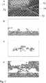
Die Berechnung der Back-/Ground- und Side-Plane-Homographie, erhöht die Trennschärfe, da eine Homographie mit weniger Freiheitsgraden Bereiche, die unterschiedliche Ebenen beinhalten, nur schlecht modellieren kann und somit korrespondierende Punkte einen höheren Rückprojektionsfehler aufweisen werden, siehe
Setzt man die statische Einbaulage der Kamera und Kamera Rotation in zwei unterschiedlichen Ansichten als gegeben voraus (z.B. durch Kenntnis der Kamera Kalibration und durch die Berechnung der Fundamental-Matrix in einem monokularen System oder durch Rotationswerte eines Drehratensensor-Clusters), lässt die inverse TTC t/d mittels der um die statische Kamera-Rotation kompensierten Flussvektoren berechnen, wie im Folgenden exemplarisch für eine Ground Plane n' = [0 1 0] gezeigt wird. Ist die Rotation nicht bekannt, kann sie näherungsweise durch eine Einheitsmatrix ersetzt werden. Ersetzt man den Quotienten t/d in Gleichung 3 durch die inverseAssuming the static mounting position of the camera and camera rotation in two different views as given (eg by knowing the camera calibration and by calculating the fundamental matrix in a monocular system or by rotation values of a rotation rate sensor cluster), the inverse TTC t / d by means of the flux vectors compensated for the static camera rotation, as shown below by way of example for a ground plane n '= [0 1 0]. Is not the rotation As is known, it can be approximately replaced by a unit matrix. If we replace the quotient t / d in equation 3 by the inverse
Time to Collision

Durch Normierung der homogenen Koordinaten ergibt sich:
Für mehr als eine Messung ergibt sich ein Gleichungssystem der Form Mx = v, mit einer Matrix M und einem Vektor v, das sich für mindestens drei Bild-Korrespondenzen durch z.B. eine Singular Value Decomposition (Singulärwertzerlegung der Matrix) oder ein Least-Square-Verfahren lösen lässt.
Die Herleitung der Back- und Side-Plane-Homographien erfolgt analog und ergibt.
Um größere, aus mehreren Zellen bestehende Objekte zu segmentieren, lassen sich in einem weiteren Schritt benachbarte Zellen zusammenfassen, indem die Rückprojektionsfehler
Wurden die Segmente zusammengefasst werden die Homographien neu berechnet und die Punkt-Korrespondenzen den Clustern mit geringstem Rückprojektionsfehler zugeordnet. Betrachtet man nur direkt angrenzende Cluster, lassen sich sehr kompakte Objekte generieren. Überschreitet der minimale Fehler eine einstellbare Schwelle, werden den Korrespondenzen neue (Cluster-/Objekt-)IDs zugewiesen, um teilverdeckte Objekte oder Objekte mit leicht unterschiedlicher TTC erkennen zu können. Durch die Einstellung der Schwelle kann die Auflösung (leicht) unterschiedlicher Objekte angepasst werden.If the segments have been combined, the homographies are recalculated and the point correspondences are assigned to the clusters with the lowest backprojection error. Looking only directly adjacent clusters can generate very compact objects. If the minimum error exceeds an adjustable threshold, the correspondences are assigned new (cluster / object) IDs in order to be able to recognize partially concealed objects or objects with slightly different TTCs. By setting the threshold, the resolution (slightly) of different objects can be adjusted.
Die Rückprojektionsfehler lassen sich mit einem Bias versehen, der Kosten für zusammenhängende Bereiche reduziert oder einem Bias, der die Kosten für einen ID-Wechsel erhöht, falls Punkt-Korrespondenzen über eine längere Zeit dieselbe ID-Zugehörigkeit hatten.The backprojection errors can be biased to reduce costs for contiguous areas or a bias that increases the cost of an ID change if point correspondences have had the same ID affiliation for a long time.
Analog dem anhand von
Wie in
Betrachtet man Gleichung 3, erkennt man, dass Segmente mit einer inversen TTC gleich Null die Rotationsmatrix beschreiben und man kann sie durch Berechnung einer Homographie mit vollen Freiheitsgrad (Gleichung 2) aus Segmenten mit t/d gleich Null bestimmen. Geht man davon aus, dass sich die translatorische Komponenten in der Nähe des Epipols nicht bemerkbar machen, kann man die Pitch und Gierrate auch bestimmen, indem die Koordinaten des Epipols durch die Homographie statischer Segmente prädiziert werden und der atan((xe0 – xe1)/f) bzw. atan((ye0 – ye1)/f) mit der auf einen Pixel bezogenen Brennweite berechnet wird.Looking at Equation 3, it can be seen that segments with an inverse TTC equal to zero describe the rotation matrix and can be determined by computing a full degree of freedom homology (Equation 2) from segments with t / d equal to zero. Assuming that the translational components in the vicinity of the epipole are not noticeable, one can also determine the pitch and yaw rate by predicating the coordinates of the epipole by the homography of static segments and the atan ((xe0 - xe1 ) / f) or atan ((ye0 -ye1 ) / f) is calculated with the pixel-related focal length.
Wird für jedes Cluster eine Homographie mit allen Freiheitsgraden berechnet, können diese auch zur Rekonstruktion der 3D Umgebung verwendet werden, indem anstelle der gemessenen Position xt0, die prädizierte Position H*xt1 zur Triangulation verwendet wird. Dies reduziert nicht nur den Einfluss von Messfehlern, sondern ermöglicht es auch Objekte nahe des Epipols zu rekonstruieren.If a homography with all degrees of freedom is calculated for each cluster, these can also be used to reconstruct the 3D environment by using the predicted position H * xt1 for triangulation instead of the measured position xt0 . This not only reduces the influence of measurement errors, but also allows objects near the epipole to be reconstructed.
Im Folgenden wird ein Ausführungsbeispiel zur Verdichtung des optischen Flusses basierend auf Homographien beschrieben.Hereinafter, an embodiment for condensing the optical flux based on homographs will be described.
Ist die Segmentierung zum Zeitpunkt t-1 bekannt, kann sie sowohl zur Prädiktion der Objekte als auch zur Generierung eines dichten Flussfeldes verwendet werden. Signaturbasierte Flussverfahren erzeugen Signaturen und versuchen diese in aufeinanderfolgenden Frames eindeutig zuzuordnen. Meist werden die Signaturen aus einem Patch definierter Größe berechnet. Verändern sich jedoch Größe und Form eines Patches, ist eine Korrespondenzfindung mit einem festen Template nicht mehr möglich. (z.B. nähert man sich einer Back-Plane an, verändert sich die Größe eines Patches, bzw. bewegt man sich über eine einer Ground-Plane oder parallel zu einer Side-Plane, verändern sich sowohl Größe als auch Form eines Patches, siehe
Alternativ lässt sich der aktuelle Frame zum Zeitpunkt t-0 auf den Zeitpunkt t-1 transformieren um Skalen und Form Änderungen zu kompensieren.
In
Zur Generierung eines dichten Flussfeldes kann also für jedes Segment das aktuelle Bild auf das vorherige Bild gewarpt werden, um bereits bestehende Korrespondenzen, die sich in ihrer Skale oder Form veränderte haben, wieder zu finden bzw. um neue Korrespondenzen mittels deckungsgleicher Templates zu etablieren. In order to generate a dense flow field, the current image can be warmed to the previous image for each segment in order to find existing correspondences that have changed in their scale or shape, or to establish new correspondences by means of congruent templates.
Sind in einem aktuellen Frame nicht genügend Flussvektoren zur Neuberechnung einer Homographie vorhanden, lassen sich näherungsweise die Homographie aus dem letzten Frame verwenden um die Korrespondenzfindung robuster gegen Form und Skalenänderungen zu gestalten.If there are not enough flow vectors in a current frame to recalculate a homography, approximately the homography from the last frame can be used to make the correspondence finding more robust against shape and scale changes.
Folgende Ausgestaltungsformen bzw. -aspekte sind vorteilhaft und können einzeln oder in Kombination vorgesehen werden:
- 1. Das Bild wird in NxM Zellen unterteilt und den Punkt-Korrespondenzen einer Zelle wird eine eindeutige Zellen-ID zugewiesen. Aus den Korrespondenzen mit gleichen IDs werden mittels RANSAC die Back-/Ground- und Side-Plane-Homographien (Gleichung 9, 10 und 10) berechnet und sowohl die Homographie mit dem geringsten Rückprojektionsfehler, als auch die zur Berechnung der Homographie verwendeten Stützstellen gespeichert. Bei RANSAC (RAndom SAmple Consensus) Verfahren wird üblicherweise bei jeder Iteration eine minimale Anzahl an zufällig ausgewählten Korrespondenzen verwendet, um eine Hypothese zu bilden. Für jedes Merkmal wird anschließend ein Wert berechnet, der beschreibt, ob das Merkmal die Hypothese unterstützt. Wenn die Hypothese eine hinreichende Unterstützung durch die Merkmale erreicht, können die nicht-unterstützenden Merkmale als Ausreißer verworfen werden. Andernfalls wird erneut eine minimale Anzahl an Korrespondenzen zufällig ausgewählt.
- 2. Für benachbarte Zellen i, j werden die Rückprojektionsfehler
Σx i / t0 – Hjx i / t1 Σx j / t0 – Hix j / t1 Σx i / t0 – Hjx i / t1 Σx i / t0 – Hix i / t1 - 3. Die Rückprojektionsfehler xt0 – Hixt1 sämtlicher Punkt-Korrespondenzen werden für die angrenzenden Segmente berechnet und eine Punkt-Korrespondenz wird dem Segment mit geringstem Rückprojektionsfehler zugeordnet. Überschreitet der minimale Fehler eine Schwelle, werden die Korrespondenzen mit einer neuen Objekt ID versehen um auch kleinere bzw. teilverdeckte Objekte erkennen zu können.
- 4. Die Homographien der zum Zeitpunkt t-1 extrahierten Segmente werden zu Beginn eines neuen Frames über die bereits gefunden Bild Korrespondenzen neu berechnet und die bereits bestehenden Segment IDs in den aktuellen Frame prädiziert. Sind im aktuellen Frame nicht genügend Flussvektoren zur Neuberechnung einer Homographie vorhanden, lassen sich näherungsweise die Homographien aus dem letzten Frame verwenden.
- 5. Zur Generierung eines dichten Flussfeldes wird für jedes Segment der aktuelle Frame auf den letzten Frame gewarpt um bereits bestehende Korrespondenzen, die sich in ihrer Skale oder Form veränderte haben, wieder zu finden bzw. um neue Korrespondenzen zu etablieren.
- 6. Die Rückprojektionsfehler der Back-/Ground- und Side-Plane können zur Validierung erhabener Ziele verwendet werden, siehe
6 . - 7. Ist z.B. bei einer Fahrzeugstereokamera eine Disparitätskarte vorhanden, können die absoluten Geschwindigkeiten aus der inversen TTC t/d berechnet werden, da dann die absoluten Entfernungen d für einzelne Pixel in der Disparitätskarte vorliegen.
- 8. Wird für jedes Segment eine vollständige Homographie mit allen Freiheitsgraden berechnet, kann aus Segmenten mit einer TTC nahe unendlich (bzw. inverse TTCs annähernd Null) die Rotationsmatrix R bestimmt werden.
- 9. Die 3D Umgebung kann aus der prädizierten Position (Hxt1, xt1) anstelle der gemessenen Position (xt0, xt1) rekonstruiert werden und erlaubt es auch Objekte am Epipol zu rekonstruieren.
- 1. The image is subdivided into NxM cells and the point correspondences of a cell are assigned a unique cell ID. From the correspondences with the same IDs RANSAC calculates the back / ground and side-plane homographies (Equations 9, 10 and 10) and stores both the homography with the lowest backprojection error and the vertices used to compute the homography. In RANSAC (RAndom SAmple Consensus) methods, a minimum number of randomly selected correspondences are usually used in each iteration to form a hypothesis. For each feature, a value is then calculated that describes whether the feature supports the hypothesis. If the hypothesis reaches sufficient support by the features, the non-supporting features may be discarded as outliers. Otherwise, a minimum number of correspondences will be randomly selected again.
- 2. For adjacent cells i, j, the backprojection errors become
Σx i / t0 - Hj xi / t1 Σx j / t0 - Hi xj / t1 Σx i / t0 - Hj xi / t1 Σx i / t0 - Hi xi / t1 - 3. The backprojection errors xt0 - Hi xt1 of all dot correspondences are calculated for the adjacent segments and a dot correspondence is assigned to the segment with least backprojection error. If the minimum error exceeds a threshold, the correspondences are provided with a new object ID in order to be able to recognize even smaller or partially hidden objects.
- 4. The homographies of the segments extracted at time t-1 are recalculated at the beginning of a new frame via the already found image correspondences and the already existing segment IDs are predicted in the current frame. If there are not enough flow vectors available in the current frame to recalculate a homography, the approximate homographies from the last frame can be used.
- 5. To generate a dense flow field, the current frame for each segment is warped to the last frame in order to find existing correspondences that have changed in their scale or shape, or to establish new correspondence.
- 6. Back-ground and side-plane backprojecting errors can be used to validate elevated targets, see
6 , - 7. If, for example, a disparity map is present in a car stereo camera, the absolute speeds can be calculated from the inverse TTC t / d, since the absolute distances d for individual pixels in the disparity map are then available.
- 8. If a complete homography with all degrees of freedom is calculated for each segment, the rotation matrix R can be determined from segments with a TTC close to infinity (or inverse TTCs approaching zero).
- 9. The 3D environment can be reconstructed from the predicted position (Hxt1 , xt1 ) instead of the measured position (xt0 , xt1 ) and also allows objects on the epipole to be reconstructed.
ZITATE ENTHALTEN IN DER BESCHREIBUNG QUOTES INCLUDE IN THE DESCRIPTION
Diese Liste der vom Anmelder aufgeführten Dokumente wurde automatisiert erzeugt und ist ausschließlich zur besseren Information des Lesers aufgenommen. Die Liste ist nicht Bestandteil der deutschen Patent- bzw. Gebrauchsmusteranmeldung. Das DPMA übernimmt keinerlei Haftung für etwaige Fehler oder Auslassungen.This list of the documents listed by the applicant has been generated automatically and is included solely for the better information of the reader. The list is not part of the German patent or utility model application. The DPMA assumes no liability for any errors or omissions.
Zitierte PatentliteraturCited patent literature
- US 2014/0161323 A1[0003]US 2014/0161323 A1[0003]
- EP 2993654 A1[0004]EP 2993654 A1[0004]
Zitierte Nicht-PatentliteraturCited non-patent literature
- Tutorial: Multiple View Geometry, Hartley, R. and Zisserman, A., CVPR June 1999: https://de.scribd.com/document/96810936/Hartley-Tut-4up abgerufen am 26.09.2016[0041]Tutorial: Multiple View Geometry, Hartley, R. and Zisserman, A., CVPR June 1999: https://en.scribd.com/document/96810936/Hartley-Tut-4up retrieved on 26.09.2016[0041]
Claims (12)
Translated fromGerman


Priority Applications (8)
| Application Number | Priority Date | Filing Date | Title |
|---|---|---|---|
| DE102016218852.6ADE102016218852A1 (en) | 2016-09-29 | 2016-09-29 | Detection of objects from images of a camera |
| DE112017003466.3TDE112017003466A5 (en) | 2016-09-29 | 2017-09-28 | Detection and validation of objects from sequential images of a camera by means of homographies |
| US16/323,826US10984263B2 (en) | 2016-09-29 | 2017-09-28 | Detection and validation of objects from sequential images of a camera by using homographies |
| PCT/DE2017/200102WO2018059631A1 (en) | 2016-09-29 | 2017-09-28 | Detection and validation of objects from sequential images from a camera by means of homographs |
| KR1020197005955AKR102491527B1 (en) | 2016-09-29 | 2017-09-28 | Detection of objects in camera images |
| CN201780060471.3ACN109791607B (en) | 2016-09-29 | 2017-09-28 | Detection and verification of objects from a series of images of a camera by means of homography matrices |
| JP2019513924AJP7050763B2 (en) | 2016-09-29 | 2017-09-28 | Detection of objects from camera images |
| EP17794220.8AEP3520024B1 (en) | 2016-09-29 | 2017-09-28 | Detection and validation of objects from sequential images of a camera using homograpies |
Applications Claiming Priority (1)
| Application Number | Priority Date | Filing Date | Title |
|---|---|---|---|
| DE102016218852.6ADE102016218852A1 (en) | 2016-09-29 | 2016-09-29 | Detection of objects from images of a camera |
Publications (1)
| Publication Number | Publication Date |
|---|---|
| DE102016218852A1true DE102016218852A1 (en) | 2018-03-29 |
Family
ID=60262655
Family Applications (2)
| Application Number | Title | Priority Date | Filing Date |
|---|---|---|---|
| DE102016218852.6AWithdrawnDE102016218852A1 (en) | 2016-09-29 | 2016-09-29 | Detection of objects from images of a camera |
| DE112017003466.3TWithdrawnDE112017003466A5 (en) | 2016-09-29 | 2017-09-28 | Detection and validation of objects from sequential images of a camera by means of homographies |
Family Applications After (1)
| Application Number | Title | Priority Date | Filing Date |
|---|---|---|---|
| DE112017003466.3TWithdrawnDE112017003466A5 (en) | 2016-09-29 | 2017-09-28 | Detection and validation of objects from sequential images of a camera by means of homographies |
Country Status (7)
| Country | Link |
|---|---|
| US (1) | US10984263B2 (en) |
| EP (1) | EP3520024B1 (en) |
| JP (1) | JP7050763B2 (en) |
| KR (1) | KR102491527B1 (en) |
| CN (1) | CN109791607B (en) |
| DE (2) | DE102016218852A1 (en) |
| WO (1) | WO2018059631A1 (en) |
Families Citing this family (9)
| Publication number | Priority date | Publication date | Assignee | Title |
|---|---|---|---|---|
| DE102016218852A1 (en)* | 2016-09-29 | 2018-03-29 | Conti Temic Microelectronic Gmbh | Detection of objects from images of a camera |
| DE102016218849A1 (en) | 2016-09-29 | 2018-03-29 | Conti Temic Microelectronic Gmbh | Detection and tracking of objects from images of a camera |
| DE102016218853A1 (en) | 2016-09-29 | 2018-03-29 | Conti Temic Microelectronic Gmbh | Detection and validation of objects from images of a camera |
| US10706587B1 (en)* | 2018-09-25 | 2020-07-07 | Amazon Technologies, Inc. | Calibration of multiple cameras |
| CN111260719B (en)* | 2020-01-09 | 2022-10-25 | 上海交通大学 | A system and method for calculating collision time based on neural network algorithm |
| CN113284197B (en)* | 2021-07-22 | 2021-11-23 | 浙江华睿科技股份有限公司 | TOF camera external reference calibration method and device for AGV, and electronic equipment |
| FR3155191A1 (en) | 2023-11-13 | 2025-05-16 | Continental Autonomous Mobility Germany GmbH | Segment detection |
| FR3155189A1 (en) | 2023-11-13 | 2025-05-16 | Continental Autonomous Mobility Germany GmbH | Anticipatory tracking of lateral objects |
| CN119705437B (en)* | 2025-01-20 | 2025-10-03 | 重庆长安汽车股份有限公司 | Vehicle forward collision warning method, device, equipment and storage medium |
Citations (2)
| Publication number | Priority date | Publication date | Assignee | Title |
|---|---|---|---|---|
| US20140161323A1 (en) | 2010-09-21 | 2014-06-12 | Mobileye Technologies Limited | Dense structure from motion |
| EP2993654A1 (en) | 2010-12-07 | 2016-03-09 | Mobileye Vision Technologies Ltd. | Method and system for forward collision warning |
Family Cites Families (34)
| Publication number | Priority date | Publication date | Assignee | Title |
|---|---|---|---|---|
| JPH11353565A (en) | 1998-06-09 | 1999-12-24 | Yazaki Corp | Vehicle collision warning method and device |
| JP3463858B2 (en) | 1998-08-27 | 2003-11-05 | 矢崎総業株式会社 | Perimeter monitoring device and method |
| US6618672B2 (en) | 1998-10-21 | 2003-09-09 | Yazaki Corporation | Vehicle-applied rear-and-side monitoring system |
| DE19926559A1 (en) | 1999-06-11 | 2000-12-21 | Daimler Chrysler Ag | Method and device for detecting objects in the vicinity of a road vehicle up to a great distance |
| JP4118452B2 (en)* | 1999-06-16 | 2008-07-16 | 本田技研工業株式会社 | Object recognition device |
| JP2002189075A (en)* | 2000-12-20 | 2002-07-05 | Fujitsu Ten Ltd | Method for detecting stationary on-road object |
| JP3895238B2 (en)* | 2002-08-28 | 2007-03-22 | 株式会社東芝 | Obstacle detection apparatus and method |
| JP3987048B2 (en)* | 2003-03-20 | 2007-10-03 | 本田技研工業株式会社 | Vehicle periphery monitoring device |
| DE10317044A1 (en) | 2003-04-11 | 2004-10-21 | Daimlerchrysler Ag | Optical monitoring system for use in maneuvering road vehicles provides virtual guide surfaces to ensure collision free movement |
| DE10351778A1 (en) | 2003-11-06 | 2005-06-09 | Daimlerchrysler Ag | Method for correspondence analysis in image data sets |
| JP4328692B2 (en) | 2004-08-11 | 2009-09-09 | 国立大学法人東京工業大学 | Object detection device |
| DE102004046101B4 (en) | 2004-09-23 | 2007-01-18 | Daimlerchrysler Ag | Method, safety device and use of the safety device for the early detection of motor vehicle collisions |
| US7130745B2 (en) | 2005-02-10 | 2006-10-31 | Toyota Technical Center Usa, Inc. | Vehicle collision warning system |
| JP4203512B2 (en)* | 2006-06-16 | 2009-01-07 | 本田技研工業株式会社 | Vehicle periphery monitoring device |
| JP4166253B2 (en)* | 2006-07-10 | 2008-10-15 | トヨタ自動車株式会社 | Object detection apparatus, object detection method, and object detection program |
| JP4267657B2 (en)* | 2006-10-31 | 2009-05-27 | 本田技研工業株式会社 | Vehicle periphery monitoring device |
| WO2008065717A1 (en)* | 2006-11-29 | 2008-06-05 | Fujitsu Limited | Pedestrian detecting system, and pedestrian detecting method |
| US8098889B2 (en) | 2007-01-18 | 2012-01-17 | Siemens Corporation | System and method for vehicle detection and tracking |
| JP5146446B2 (en)* | 2007-03-22 | 2013-02-20 | 日本電気株式会社 | MOBILE BODY DETECTION DEVICE, MOBILE BODY DETECTING PROGRAM, AND MOBILE BODY DETECTING METHOD |
| EP1988488A1 (en)* | 2007-05-03 | 2008-11-05 | Sony Deutschland Gmbh | Method for detecting moving objects in a blind spot region of a vehicle and blind spot detection device |
| JP2009100342A (en) | 2007-10-18 | 2009-05-07 | Sanyo Electric Co Ltd | Camera calibration device, method and vehicle |
| JP5410730B2 (en) | 2008-10-09 | 2014-02-05 | 日立オートモティブシステムズ株式会社 | Automobile external recognition device |
| DE102009028742A1 (en) | 2009-08-20 | 2011-02-24 | Robert Bosch Gmbh | Method and control device for determining a movement information of an object |
| US8232872B2 (en) | 2009-12-03 | 2012-07-31 | GM Global Technology Operations LLC | Cross traffic collision alert system |
| US9118816B2 (en) | 2011-12-06 | 2015-08-25 | Mobileye Vision Technologies Ltd. | Road vertical contour detection |
| DE102011006564B4 (en)* | 2011-03-31 | 2025-08-28 | Robert Bosch Gmbh | Method for evaluating an image taken by a camera of a vehicle and image processing device |
| EP2546804A1 (en) | 2011-07-10 | 2013-01-16 | Dürr Dental AG | Method and tomography apparatus for reconstruction of a 3D volume |
| JP5944781B2 (en)* | 2012-07-31 | 2016-07-05 | 株式会社デンソーアイティーラボラトリ | Mobile object recognition system, mobile object recognition program, and mobile object recognition method |
| US9256791B2 (en)* | 2012-12-04 | 2016-02-09 | Mobileye Vision Technologies Ltd. | Road vertical contour detection |
| EP3143607A1 (en) | 2014-05-14 | 2017-03-22 | Mobileye Vision Technologies Ltd. | Systems and methods for curb detection and pedestrian hazard assessment |
| DE102015224796A1 (en) | 2015-12-10 | 2017-06-14 | Robert Bosch Gmbh | Method and control unit for detecting a possible collision of an unmanned aerial vehicle with an object |
| DE102016218853A1 (en) | 2016-09-29 | 2018-03-29 | Conti Temic Microelectronic Gmbh | Detection and validation of objects from images of a camera |
| DE102016218849A1 (en) | 2016-09-29 | 2018-03-29 | Conti Temic Microelectronic Gmbh | Detection and tracking of objects from images of a camera |
| DE102016218852A1 (en)* | 2016-09-29 | 2018-03-29 | Conti Temic Microelectronic Gmbh | Detection of objects from images of a camera |
- 2016
- 2016-09-29DEDE102016218852.6Apatent/DE102016218852A1/ennot_activeWithdrawn
- 2017
- 2017-09-28KRKR1020197005955Apatent/KR102491527B1/enactiveActive
- 2017-09-28WOPCT/DE2017/200102patent/WO2018059631A1/ennot_activeCeased
- 2017-09-28EPEP17794220.8Apatent/EP3520024B1/enactiveActive
- 2017-09-28USUS16/323,826patent/US10984263B2/enactiveActive
- 2017-09-28CNCN201780060471.3Apatent/CN109791607B/enactiveActive
- 2017-09-28JPJP2019513924Apatent/JP7050763B2/enactiveActive
- 2017-09-28DEDE112017003466.3Tpatent/DE112017003466A5/ennot_activeWithdrawn
Patent Citations (2)
| Publication number | Priority date | Publication date | Assignee | Title |
|---|---|---|---|---|
| US20140161323A1 (en) | 2010-09-21 | 2014-06-12 | Mobileye Technologies Limited | Dense structure from motion |
| EP2993654A1 (en) | 2010-12-07 | 2016-03-09 | Mobileye Vision Technologies Ltd. | Method and system for forward collision warning |
Non-Patent Citations (1)
| Title |
|---|
| Tutorial: Multiple View Geometry, Hartley, R. and Zisserman, A., CVPR June 1999: https://de.scribd.com/document/96810936/Hartley-Tut-4up abgerufen am 26.09.2016 |
Also Published As
| Publication number | Publication date |
|---|---|
| CN109791607B (en) | 2024-06-04 |
| DE112017003466A5 (en) | 2019-03-21 |
| WO2018059631A1 (en) | 2018-04-05 |
| EP3520024B1 (en) | 2024-09-11 |
| JP7050763B2 (en) | 2022-04-08 |
| KR102491527B1 (en) | 2023-01-20 |
| KR20190059894A (en) | 2019-05-31 |
| CN109791607A (en) | 2019-05-21 |
| US20190180121A1 (en) | 2019-06-13 |
| US10984263B2 (en) | 2021-04-20 |
| JP2019530924A (en) | 2019-10-24 |
| EP3520024A1 (en) | 2019-08-07 |
Similar Documents
| Publication | Publication Date | Title |
|---|---|---|
| EP3520024B1 (en) | Detection and validation of objects from sequential images of a camera using homograpies | |
| EP3520025B1 (en) | Detection and validation of objects from sequential images of a camera using homograpies | |
| DE69624980T2 (en) | Object monitoring method and device with two or more cameras | |
| EP3520023B1 (en) | Detection and validation of objects from sequential images of a camera | |
| DE102014213981A1 (en) | Parking lot detection device and corresponding method | |
| DE102009009047A1 (en) | Method for object detection | |
| DE102012101014A1 (en) | Vehicle detection device | |
| DE102014112820A1 (en) | Vehicle exterior environment recognition device | |
| DE102018121008B4 (en) | SYSTEM FOR DRIVING AN AUTONOMOUS VEHICLE AND VEHICLE EQUIPPED THEREFROM | |
| DE102016104730A1 (en) | Method for detecting an object along a road of a motor vehicle, computing device, driver assistance system and motor vehicle | |
| EP2023265A1 (en) | Method for recognising an object | |
| DE102013113960A1 (en) | Road surface shape determining device | |
| DE102019208216A1 (en) | Detection, 3D reconstruction and tracking of several rigid objects moving relative to one another | |
| DE102013012930A1 (en) | Method for determining a current distance and / or a current speed of a target object from a reference point in a camera image, camera system and motor vehicle | |
| DE102018100909A1 (en) | Method of reconstructing images of a scene taken by a multifocal camera system | |
| DE102015211874A1 (en) | Object detection device | |
| EP4229549A1 (en) | System and method for annotating car radar data | |
| DE102019214558A1 (en) | PROJECTION INFORMATION RECOGNITION DEVICE BASED ON AN ARTIFICIAL NEURAL NETWORK AND PROCESSES OF THE SAME | |
| DE102015211871A1 (en) | Object detection device | |
| DE102019209473A1 (en) | Method and device for the rapid detection of repetitive structures in the image of a street scene | |
| DE102016218851A1 (en) | Compaction of an optical flow field for the detection of objects from images of a camera | |
| DE102015204529A1 (en) | Method and device for object recognition in a means of transportation | |
| WO2022042903A1 (en) | Method for identifying three-dimensional objects, computer program, machine-readable storage medium, control unit, vehicle and video monitoring system | |
| DE102018202753A1 (en) | Method for determining a distance between a motor vehicle and an object | |
| DE102014009139A1 (en) | Lane detection method and lane detection system using a photographing unit |
Legal Events
| Date | Code | Title | Description |
|---|---|---|---|
| R083 | Amendment of/additions to inventor(s) | ||
| R163 | Identified publications notified | ||
| R118 | Application deemed withdrawn due to claim for domestic priority |