DE102016218313A1 - Portable machine tool - Google Patents
Portable machine toolDownload PDFInfo
- Publication number
- DE102016218313A1 DE102016218313A1DE102016218313.3ADE102016218313ADE102016218313A1DE 102016218313 A1DE102016218313 A1DE 102016218313A1DE 102016218313 ADE102016218313 ADE 102016218313ADE 102016218313 A1DE102016218313 A1DE 102016218313A1
- Authority
- DE
- Germany
- Prior art keywords
- unit
- electric motor
- motor unit
- machine tool
- coupling device
- Prior art date
- Legal status (The legal status is an assumption and is not a legal conclusion. Google has not performed a legal analysis and makes no representation as to the accuracy of the status listed.)
- Pending
Links
- 238000005520cutting processMethods0.000claimsabstractdescription111
- 230000008878couplingEffects0.000claimsabstractdescription54
- 238000010168coupling processMethods0.000claimsabstractdescription54
- 238000005859coupling reactionMethods0.000claimsabstractdescription54
- 238000009434installationMethods0.000description8
- 238000003754machiningMethods0.000description7
- 238000000034methodMethods0.000description5
- 239000000463materialSubstances0.000description3
- 239000002245particleSubstances0.000description3
- 230000005540biological transmissionEffects0.000description2
- 230000003993interactionEffects0.000description2
- 238000004519manufacturing processMethods0.000description2
- 238000000926separation methodMethods0.000description2
- 239000000853adhesiveSubstances0.000description1
- 230000001070adhesive effectEffects0.000description1
- 238000005266castingMethods0.000description1
- 239000003795chemical substances by applicationSubstances0.000description1
- 238000010276constructionMethods0.000description1
- 230000001276controlling effectEffects0.000description1
- 230000000694effectsEffects0.000description1
- 238000002347injectionMethods0.000description1
- 239000007924injectionSubstances0.000description1
- 238000001746injection mouldingMethods0.000description1
- 230000001105regulatory effectEffects0.000description1
- 239000002904solventSubstances0.000description1
- 239000000126substanceSubstances0.000description1
- 238000003466weldingMethods0.000description1
Images

Classifications
- B—PERFORMING OPERATIONS; TRANSPORTING
- B25—HAND TOOLS; PORTABLE POWER-DRIVEN TOOLS; MANIPULATORS
- B25F—COMBINATION OR MULTI-PURPOSE TOOLS NOT OTHERWISE PROVIDED FOR; DETAILS OR COMPONENTS OF PORTABLE POWER-DRIVEN TOOLS NOT PARTICULARLY RELATED TO THE OPERATIONS PERFORMED AND NOT OTHERWISE PROVIDED FOR
- B25F5/00—Details or components of portable power-driven tools not particularly related to the operations performed and not otherwise provided for
- B25F5/02—Construction of casings, bodies or handles
Landscapes
- Engineering & Computer Science (AREA)
- Mechanical Engineering (AREA)
- Sawing (AREA)
Abstract
Translated fromGermanDescription
Translated fromGermanStand der TechnikState of the art
Es sind bereits tragbare Werkzeugmaschinen mit zumindest einer Kopplungsvorrichtung zu einer formschlüssigen und/oder kraftschlüssigen Kopplung mit einer Einsatzwerkzeugeinheit, die zumindest einen Schneidstrang und eine Führungseinheit umfasst, und mit zumindest einer Elektromotoreinheit zu einem Antrieb der Einsatzwerkzeugeinheit in einem mit der Kopplungsvorrichtung gekoppelten Zustand der Einsatzwerkzeugeinheit bekannt.There are already portable machine tools with at least one coupling device for a positive and / or non-positive coupling with an insert tool unit comprising at least one cutting strand and a guide unit, and with at least one electric motor unit for driving the insert tool unit in a coupled to the coupling device state of the insert tool unit known ,
Offenbarung der ErfindungDisclosure of the invention
Die Erfindung geht aus von einer tragbaren Werkzeugmaschine, insbesondere von einer Sägemaschine, mit zumindest einer Kopplungsvorrichtung zu einer formschlüssigen und/oder kraftschlüssigen Kopplung mit einer Einsatzwerkzeugeinheit, die zumindest einen Schneidstrang und eine Führungseinheit umfasst, und mit zumindest einer Elektromotoreinheit zu einem Antrieb der Einsatzwerkzeugeinheit in einem mit der Kopplungsvorrichtung gekoppelten Zustand der Einsatzwerkzeugeinheit.The invention relates to a portable machine tool, in particular a sawing machine, with at least one coupling device for a positive and / or non-positive coupling with an insert tool unit comprising at least one cutting strand and a guide unit, and with at least one electric motor unit for driving the insert tool unit in a coupled to the coupling device state of the insert tool unit.
Es wird vorgeschlagen, dass die Elektromotoreinheit als Direktantriebseinheit ausgebildet ist, die in einem mit der Kopplungsvorrichtung gekoppelten Zustand der Einsatzwerkzeugeinheit getriebefrei mit der Einsatzwerkzeugeinheit in Wirkverbindung steht. Unter „getriebefrei in Wirkverbindung stehen“ soll insbesondere ein Zusammenwirken von zumindest zwei Elementen und/oder Einheiten, insbesondere der Elektromotoreinheit und der Einsatzwerkzeugeinheit, verstanden werden, wobei die Elemente und/oder Einheiten zu einer Kraft- und/oder Drehmomentverbindung entkoppelt von einer Getriebeeinheit miteinander verbunden sind. Vorzugsweise ist zwischen der Elektromotoreinheit und der Einsatzwerkzeugeinheit keine Getriebeeinheit angeordnet. Bevorzugt greift die Elektromotoreinheit, insbesondere ein Antriebsritzel der Elektromotoreinheit, zu einer Kraft- und/oder Drehmomentverbindung direkt in die Elektrowerkzeugeinheit ein. Die Elektrowerkzeugeinheit, insbesondere der Schneidstrang, wird vorzugsweise direkt mittels der Elektromotoreinheit, insbesondere mittels des Antriebsritzels, angetrieben.It is proposed that the electric motor unit is designed as a direct drive unit, which is in a coupled with the coupling device state of the insert tool unit gearless with the insert tool unit in operative connection. Under "gear free in operative connection" should be understood in particular an interaction of at least two elements and / or units, in particular the electric motor unit and the tool insert unit, wherein the elements and / or units to a force and / or torque connection decoupled from a transmission unit with each other are connected. Preferably, no gear unit is arranged between the electric motor unit and the insert tool unit. Preferably, the electric motor unit, in particular a drive pinion of the electric motor unit, engages directly into the power tool unit for a force and / or torque connection. The power tool unit, in particular the cutting strand, is preferably driven directly by means of the electric motor unit, in particular by means of the drive pinion.
Bevorzugt bilden der Schneidstrang und die Führungseinheit der Einsatzwerkzeugeinheit zusammen ein geschlossenes System. Der Begriff „geschlossenes System“ soll hier insbesondere ein System definieren, das zumindest zwei Komponenten, insbesondere den Schneidstrang und die Führungseinheit, umfasst, die mittels eines Zusammenwirkens in einem demontierten Zustand des Systems von einem dem System übergeordneten System, wie beispielsweise einer tragbaren Werkzeugmaschine, eine Funktionalität beibehalten und/oder die im demontierten Zustand unverlierbar miteinander verbunden sind. Bevorzugt sind die zumindest zwei Komponenten des geschlossenen Systems für einen Bediener zumindest im Wesentlichen unlösbar miteinander verbunden. Unter „zumindest im Wesentlichen unlösbar“ soll hier insbesondere eine Verbindung von zumindest zwei Bauteilen verstanden werden, die lediglich unter der Zuhilfenahme von Trennwerkzeugen, wie beispielsweise einer Säge, insbesondere einer mechanischen Säge usw., und/oder chemischen Trennmitteln, wie beispielsweise Lösungsmittel usw., voneinander trennbar sind. Der Schneidstrang und die Führungseinheit sind bevorzugt als Einheit an der Kopplungsvorrichtung montierbar und/oder von der Kopplungsvorrichtung demontierbar.Preferably, the cutting strand and the guide unit of the insert tool unit together form a closed system. The term "closed system" is intended here to define in particular a system comprising at least two components, in particular the cutting strand and the guide unit, which, by means of an interaction in a disassembled state of the system, are performed by a superordinate system, such as a portable machine tool. maintain a functionality and / or are permanently connected to each other in the disassembled state. Preferably, the at least two components of the closed system are at least substantially inseparably connected with each other for an operator. By "at least substantially insoluble" should be understood in particular a combination of at least two components that only with the aid of separation tools, such as a saw, in particular a mechanical saw, etc., and / or chemical release agents, such as solvents, etc. , are separable from each other. The cutting strand and the guide unit are preferably mounted as a unit on the coupling device and / or disassembled from the coupling device.
Vorzugsweise weist der Schneidstrang entlang einer zumindest im Wesentlichen senkrecht zu einer Schneidebene des Schneidstrangs verlaufenden Richtung eine maximale Abmessung auf, die kleiner ist als 4 mm. Bevorzugt ist die maximale Abmessung entlang der zumindest im Wesentlichen senkrecht zur Schneidebene des Schneidstrangs verlaufenden Richtung als maximale Breite des Schneidstrangs ausgebildet. Besonders bevorzugt weist der Schneidstrang entlang der zumindest im Wesentlichen senkrecht zur Schneidebene des Schneidstrangs verlaufenden Richtung entlang einer Gesamtlänge des Schneidstrangs eine zumindest im Wesentlichen gleichbleibende maximale Abmessung auf. Die maximale Abmessung entspricht entlang der Gesamtlänge des Schneidstrangs bevorzugt einem Wert aus einem Wertebereich von 1 mm bis 3 mm. Vorzugsweise ist der Schneidstrang dazu vorgesehen, einen Schneidspalt zu erzeugen, der entlang der zumindest im Wesentlichen senkrecht zur Schneidebene des Schneidstrangs verlaufenden Richtung eine maximale Abmessung kleiner als 4 mm aufweist. Unter „vorgesehen“ soll insbesondere speziell ausgelegt und/oder speziell ausgestattet verstanden werden. Besonders vorteilhaft können Schneidspalte mit geringen Abmessungen erzeugt werden, indem der Schneidstrang entlang der zumindest im Wesentlichen senkrecht zur Schneidebene des Schneidstrangs verlaufenden Richtung eine maximale Abmessung zwischen 1,3 mm bis 2,2 mm aufweist. Vorzugsweise ist der Schneidstrang dazu vorgesehen, einen Schneidspalt zu erzeugen, der entlang der zumindest im Wesentlichen senkrecht zur Schneidebene des Schneidstrangs verlaufenden Richtung eine maximal Abmessung zwischen 1,3 mm bis 2,2 mm aufweist. Es ist jedoch auch denkbar, dass der Schneidstrang entlang der zumindest im Wesentlichen senkrecht zur Schneidebene des Schneidstrangs verlaufenden Richtung eine maximale Abmessung aufweist, die kleiner ist als 1,3 mm und größer als 0 mm. Unter einem „Schneidstrang“ soll hier insbesondere eine Einheit verstanden werden, die dazu vorgesehen ist, einen atomaren Zusammenhalt eines zu bearbeitenden Werkstücks örtlich aufzuheben, insbesondere mittels eines mechanischen Abtrennens und/oder mittels eines mechanischen Abtragens von Werkstoffteilchen des Werkstücks. Bevorzugt ist der Schneidstrang dazu vorgesehen, das Werkstück in zumindest zwei physikalisch voneinander getrennte Teile zu separieren und/oder zumindest teilweise Werkstoffteilchen des Werkstücks ausgehend von einer Oberfläche des Werkstücks abzutrennen und/oder abzutragen. Der Schneidstrang ist besonders bevorzugt als endloser Schneidstrang, insbesondere als Schneidkette, ausgebildet, der entlang eines Umfangs der Führungseinheit umlaufend und/oder oszillierend antreibbar ist. Unter einer „Führungseinheit“ soll hier insbesondere eine Einheit verstanden werden, die dazu vorgesehen ist, eine Zwangskraft zumindest entlang einer Richtung senkrecht zu einer Schneidrichtung des Schneidstrangs auf den Schneidstrang auszuüben, um eine Bewegungsmöglichkeit des Schneidstrangs entlang der Schneidrichtung vorzugeben. Bevorzugt weist die Führungseinheit zumindest ein Führungselement auf, insbesondere ein Führungsschwert mit einer daran angeordneten Führungsnut, durch das der Schneidstrang geführt wird. Bevorzugt ist der Schneidstrang, in der Schneidebene des Schneidstrangs betrachtet, entlang eines gesamten Umfangs der Führungseinheit durch die Führungseinheit mittels des Führungselements geführt. Bevorzugt ist die Schneidebene bei einer Bearbeitung eines Werkstücks quer zu einer bearbeitenden Werkstückoberfläche ausgerichtet. Es ist jedoch auch denkbar, dass die Schneidebene bei einer Bearbeitung eines Werkstücks zumindest im Wesentlichen parallel zu einer bearbeitenden Werkstückoberfläche ausgerichtet ist, insbesondere bei einer Ausbildung des Schneidstrangs als Schleifmittel usw.The cutting strand preferably has a maximum dimension which is smaller than 4 mm along a direction extending at least substantially perpendicularly to a cutting plane of the cutting strand. Preferably, the maximum dimension along the at least substantially perpendicular to the cutting plane of the cutting strand extending direction is formed as the maximum width of the cutting strand. Particularly preferably, the cutting strand along the at least substantially perpendicular to the cutting plane of the cutting strand extending along an entire length of the cutting strand on an at least substantially constant maximum dimension. The maximum dimension along the entire length of the cutting strand preferably corresponds to a value from a value range of 1 mm to 3 mm. The cutting strand is preferably provided to produce a cutting gap which has a maximum dimension smaller than 4 mm along the direction running at least substantially perpendicular to the cutting plane of the cutting strand. By "intended" is intended to be understood in particular specifically designed and / or specially equipped. Particularly advantageous cutting gaps can be produced with small dimensions by the cutting strand along the at least substantially perpendicular to the cutting plane of the cutting strand extending direction has a maximum dimension between 1.3 mm to 2.2 mm. The cutting strand is preferably provided to generate a cutting gap which has a maximum dimension of between 1.3 mm and 2.2 mm along the direction extending at least substantially perpendicular to the cutting plane of the cutting strand. However, it is also conceivable that the cutting strand along the at least substantially perpendicular to the cutting plane of the cutting strand extending direction has a maximum dimension which is smaller than 1.3 mm and greater than 0 mm. A "cutting strand" is to be understood here as meaning, in particular, a unit which is intended to be a atomic cohesion of a workpiece to be machined locally, in particular by means of a mechanical separation and / or by means of a mechanical removal of material particles of the workpiece. Preferably, the cutting strand is intended to separate the workpiece into at least two physically separate parts and / or at least partially separate material particles of the workpiece, starting from a surface of the workpiece and / or remove. The cutting strand is particularly preferably designed as an endless cutting strand, in particular as a cutting chain, which is circumferentially and / or oscillating drivable along a circumference of the guide unit. A "guide unit" is to be understood here in particular as a unit which is provided to exert a constraining force on the cutting strand at least along a direction perpendicular to a cutting direction of the cutting strand, in order to predetermine a possibility of movement of the cutting strand along the cutting direction. Preferably, the guide unit has at least one guide element, in particular a guide blade with a guide groove arranged thereon, through which the cutting strand is guided. Preferably, the cutting strand, viewed in the cutting plane of the cutting strand, guided along an entire circumference of the guide unit by the guide unit by means of the guide member. Preferably, the cutting plane is aligned in a processing of a workpiece transversely to a machined workpiece surface. However, it is also conceivable that the cutting plane is aligned at a machining of a workpiece at least substantially parallel to a machined workpiece surface, in particular when forming the cutting strand as an abrasive, etc.
Der Begriff „Schneidebene“ soll hier insbesondere eine Ebene definieren, in der der Schneidstrang in zumindest einem Betriebszustand entlang eines Umfangs der Führungseinheit in zumindest zwei zueinander entgegengesetzt gerichtete Schneidrichtungen relativ zur Führungseinheit bewegt wird. Unter „zumindest im Wesentlichen parallel“ soll hier insbesondere eine Ausrichtung einer Richtung relativ zu einer Bezugsrichtung, insbesondere in einer Ebene, verstanden werden, wobei die Richtung gegenüber der Bezugsrichtung eine Abweichung insbesondere kleiner als 8°, vorteilhaft kleiner als 5° und besonders vorteilhaft kleiner als 2° aufweist. Ferner soll hier unter „zumindest im Wesentlichen senkrecht“ insbesondere eine Ausrichtung einer Richtung relativ zu einer Bezugsrichtung definieren, wobei die Richtung und die Bezugsrichtung, insbesondere in einer Ebene betrachtet, einen Winkel von 90° einschließen und der Winkel eine maximale Abweichung von insbesondere kleiner als 8°, vorteilhaft kleiner als 5° und besonders vorteilhaft kleiner als 2° aufweist. Unter einer „Schneidrichtung“ soll insbesondere eine Richtung verstanden werden, entlang der der Schneidstrang zur Erzeugung eines Schneidspalts und/oder zur Abtrennung und/oder zur Abtragung von Werkstoffteilchen eines zu bearbeitenden Werkstücks in zumindest einem Betriebszustand infolge einer Antriebskraft und/oder eines Antriebsmoments, insbesondere an der Führungseinheit, bewegt wird. Bevorzugt wird der Schneidstrang in einem Betriebszustand entlang der Schneidrichtung relativ zur Führungseinheit in der Führungsnut der Führungseinheit bewegt.The term "cutting plane" should in particular define a plane in which the cutting strand is moved in at least one operating state along a circumference of the guide unit in at least two mutually oppositely directed cutting directions relative to the guide unit. By "at least substantially parallel" should be understood here in particular an orientation of a direction relative to a reference direction, in particular in a plane, wherein the direction relative to the reference direction a deviation in particular less than 8 °, advantageously less than 5 ° and particularly advantageously smaller than 2 °. In addition, "orientation at least substantially perpendicularly" should in particular define an orientation of a direction relative to a reference direction, the direction and the reference direction, in particular in one plane, including an angle of 90 ° and the angle a maximum deviation of, in particular, smaller than 8 °, advantageously less than 5 ° and particularly advantageously less than 2 °. A "cutting direction" is to be understood in particular as meaning a direction along which the cutting strand is used to generate a cutting gap and / or to remove and / or remove material particles of a workpiece to be machined in at least one operating state as a result of a drive force and / or a drive torque on the guide unit, is moved. Preferably, the cutting strand is moved in an operating state along the cutting direction relative to the guide unit in the guide groove of the guide unit.
Vorzugsweise weist die Einsatzwerkzeugeinheit, insbesondere der Schneidstrang zusammen mit der Führungseinheit entlang einer zumindest im Wesentlichen parallel zur Schneidebene des Schneidstrangs und zumindest im Wesentlichen senkrecht zu einer Haupterstreckungsrichtung der Führungseinheit verlaufenden Richtung eine maximale Abmessung auf, die kleiner ist als 50 mm. Bevorzugt weist die Einsatzwerkzeugeinheit, insbesondere der Schneidstrang zusammen mit der Führungseinheit entlang der zumindest im Wesentlichen parallel zur Schneidebene des Schneidstrangs und zumindest im Wesentlichen senkrecht zur Haupterstreckungsrichtung der Führungseinheit verlaufenden Richtung eine maximale Abmessung auf, die kleiner ist als 30 mm, besonders bevorzugt kleiner ist als 25 mm. Die maximale Abmessung ist bevorzugt als maximale Gesamthöhe der Einsatzwerkzeugeinheit, insbesondere des Schneidstrangs zusammen mit der Führungseinheit, ausgebildet. Besonders bevorzugt weist die Einsatzwerkzeugeinheit eine maximale Gesamthöhe entlang einer Gesamterstreckung der Einsatzwerkzeugeinheit mit einem Wert aus einem Wertebereich von 5 mm bis 40 mm auf. Unter einer „Haupterstreckungsrichtung der Führungseinheit“ soll hier insbesondere eine Richtung verstanden werden, entlang der die Führungseinheit eine maximale Erstreckung aufweist. Bevorzugt weist die Einsatzwerkzeugeinheit eine maximale Gesamtmasse auf, die kleiner ist als 500 g. Bevorzugt weist die Einsatzwerkzeugeinheit eine maximale Gesamtmasse auf, die kleiner ist als 100 g und besonders bevorzugt kleiner ist als 50 g.Preferably, the insert tool unit, in particular the cutting strand together with the guide unit along a at least substantially parallel to the cutting plane of the cutting strand and at least substantially perpendicular to a main extension direction of the guide unit extending direction has a maximum dimension which is smaller than 50 mm. Preferably, the insert tool unit, in particular the cutting strand together with the guide unit along the at least substantially parallel to the cutting plane of the cutting strand and at least substantially perpendicular to the main extension direction of the guide unit extending direction has a maximum dimension which is smaller than 30 mm, particularly preferably smaller than 25 mm. The maximum dimension is preferably designed as the maximum overall height of the insert tool unit, in particular of the cutting strand together with the guide unit. Particularly preferably, the insert tool unit has a maximum overall height along a total extension of the insert tool unit with a value from a value range of 5 mm to 40 mm. A "main direction of extension of the guide unit" is to be understood here in particular as a direction along which the guide unit has a maximum extent. Preferably, the insert tool unit has a maximum total mass that is less than 500 g. Preferably, the insert tool unit has a maximum total mass which is less than 100 g and more preferably less than 50 g.
Die tragbare Werkzeugmaschine und die Einsatzwerkzeugeinheit bilden vorzugsweise ein Handwerkzeugmaschinensystem. Die tragbare Werkzeugmaschine ist vorzugsweise als Sägemaschine mit zumindest einem umlaufend antreibbaren Schneidstrang, insbesondere einer umlaufend antreibbaren Schneidkette ausgebildet. Unter einer „tragbaren Werkzeugmaschine“ soll hier insbesondere eine Werkzeugmaschine, insbesondere eine Handwerkzeugmaschine, verstanden werden, die von einem Bediener transportmaschinenlos transportiert werden kann. Die tragbare Werkzeugmaschine weist insbesondere eine Masse auf, die kleiner ist als 40 kg, bevorzugt kleiner als 10 kg und besonders bevorzugt kleiner als 5 kg sowie ganz besonders bevorzugt kleiner als 1,5 kg. Vorzugsweise ist die tragbare Werkzeugmaschine als akkubetreibbare tragbare Werkzeugmaschine ausgebildet. Es ist jedoch auch denkbar, dass die tragbare Werkzeugmaschine als kabelgebunden antreibbare tragbare Werkzeugmaschine ausgebildet ist. Bevorzugt umfasst die tragbare Werkzeugmaschine zumindest eine Akkumulatoreinheit, insbesondere einen Akkupack. Die Akkumulatoreinheit weist vorzugsweise eine Nennspannung von 18 V auf. Es ist jedoch auch denkbar, dass die Akkumulatoreinheit eine von 18 V abweichende Nennspannung aufweist, wie beispielsweise eine Nennspannung von 12 V, von 24 V von 48 V o. dgl. Mittels der erfindungsgemäßen Ausgestaltung der tragbaren Werkzeugmaschine kann vorteilhaft eine besonders kompakt tragbare Werkzeugmaschine realisiert werden. Es können vorteilhaft Bauteile und Montagekosten eingespart werden. Es kann vorteilhaft eine tragbare Werkzeugmaschine mit einer geringen Komplexität im Hinblick auf eine Kraft- und/oder Drehmomenteinwirkung auf die Einsatzwerkzeugeinheit realisiert werden.The portable machine tool and the insert tool unit preferably form a hand-held power tool system. The portable power tool is preferably designed as a sawing machine with at least one circumferentially drivable cutting strand, in particular a circumferentially drivable cutting chain. A "portable machine tool" is to be understood here in particular as meaning a machine tool, in particular a hand tool machine, which can be transported without transport machine by an operator. In particular, the portable power tool has a mass that is less than 40 kg, preferably less than 10 kg, and especially preferably less than 5 kg and most preferably less than 1.5 kg. Preferably, the portable power tool is designed as a battery-powered portable power tool. However, it is also conceivable that the portable power tool is designed as a portable portable power tool that can be driven by cable. Preferably, the portable power tool comprises at least one accumulator unit, in particular a battery pack. The accumulator unit preferably has a nominal voltage of 18V. However, it is also conceivable that the accumulator unit has a deviating from 18 V nominal voltage, such as a rated voltage of 12 V, 24 V of 48 V o. The like. By means of the inventive design of the portable power tool can advantageously realized a particularly compact portable machine tool become. It can be advantageously saved components and installation costs. It can be advantageously realized a portable machine tool with a low complexity in terms of a force and / or torque on the insert tool unit.
Des Weiteren wird vorgeschlagen, dass die Elektromotoreinheit zumindest ein Antriebselement, insbesondere ein Antriebsritzel, umfasst, das drehfest mit einer Antriebswelle, insbesondere einer Rotorwelle, der Elektromotoreinheit verbunden ist und zu einem Antrieb des Schneidstrangs vorgesehen ist, insbesondere infolge eines direkten Eingriffs des Antriebselements in den Schneidstrang. Zu einer Kopplung der Einsatzwerkzeugeinheit mit der Kopplungsvorrichtung ist vorzugsweise das Antriebselement, insbesondere das Antriebsritzel der Elektromotoreinheit, mit dem an der Führungseinheit angeordneten Schneidstrang verbindbar, insbesondere infolge einer Anordnung der Führungseinheit an der Kopplungsvorrichtung ohne eine separate Montage des Schneidstrangs an der Führungseinheit. Das Antriebselement, insbesondere das Antriebsritzel, kann einteilig mit einer Rotorwelle der Elektromotoreinheit ausgebildet sein oder mittels einer form- und/oder kraftschlüssigen Verbindung drehfest an der Rotorwelle angeordnet sein. Unter „einteilig“ soll hier insbesondere zumindest stoffschlüssig verbunden verstanden werden, beispielsweise durch einen Schweißprozess, einen Klebeprozess, einen Anspritzprozess und/oder einen anderen, einem Fachmann als sinnvoll erscheinenden Prozess, und/oder vorteilhaft in einem Stück geformt verstanden werden, wie beispielsweise durch eine Herstellung aus einem Guss und/oder durch eine Herstellung in einem Ein- oder Mehrkomponentenspritzverfahren und vorteilhaft aus einem einzelnen Rohling. Vorzugsweise greift die Elektromotoreinheit, insbesondere das Antriebsritzel, direkt in den Schneidstrang der Einsatzwerkzeugeinheit ein, insbesondere in einem mit der Kopplungsvorrichtung gekoppelten Zustand der Einsatzwerkzeugeinheit. Mittels der erfindungsgemäßen Ausgestaltung der tragbaren Werkzeugmaschine kann vorteilhaft eine besonders kompakt tragbare Werkzeugmaschine realisiert werden. Es können vorteilhaft Bauteile und Montagekosten eingespart werden. Es kann vorteilhaft eine tragbare Werkzeugmaschine mit einer geringen Komplexität im Hinblick auf eine Kraft- und/oder Drehmomenteinwirkung auf die Einsatzwerkzeugeinheit realisiert werden. Es kann konstruktiv einfach eine Direktantriebseinheit realisiert werden. Es kann vorteilhaft ein direkter Antrieb des Schneidstrangs entkoppelt von einem zwischengeschalteten Getriebe ermöglicht werden. Es kann vorteilhaft eine geringe Komplexität eines Aufbaus der tragbaren Werkzeugmaschine realisiert werden.Furthermore, it is proposed that the electric motor unit comprises at least one drive element, in particular a drive pinion, which is non-rotatably connected to a drive shaft, in particular a rotor shaft, the electric motor unit and is provided for driving the cutting strand, in particular as a result of direct engagement of the drive element in the cutting strand. For a coupling of the insert tool unit with the coupling device is preferably the drive element, in particular the drive pinion of the electric motor unit, connected to the arranged on the guide unit cutting strand, in particular due to an arrangement of the guide unit on the coupling device without a separate mounting of the cutting strand on the guide unit. The drive element, in particular the drive pinion, may be integrally formed with a rotor shaft of the electric motor unit or may be arranged non-rotatably on the rotor shaft by means of a positive and / or non-positive connection. By "one-piece" should be understood here in particular as being at least materially bonded, for example by a welding process, an adhesive process, an injection process and / or another process that appears expedient to a person skilled in the art, and / or advantageously shaped in one piece, for example by a production from a casting and / or by a production in a one-component or multi-component injection molding process and advantageously from a single blank. Preferably, the electric motor unit, in particular the drive pinion, engages directly into the cutting strand of the insert tool unit, in particular in a state of the insert tool unit coupled to the coupling device. By means of the embodiment of the portable power tool according to the invention can advantageously be realized a particularly compact portable machine tool. It can be advantageously saved components and installation costs. It can be advantageously realized a portable machine tool with a low complexity in terms of a force and / or torque on the insert tool unit. It can be realized structurally simple a direct drive unit. Advantageously, a direct drive of the cutting strand can be made decoupled from an intermediate transmission. Advantageously, a low complexity of a construction of the portable power tool can be realized.
Ferner wird vorgeschlagen, dass die tragbare Werkzeugmaschine zumindest ein Gehäuse umfasst, wobei die Elektromotoreinheit zumindest einen Rotor und zumindest einen Stator aufweist, die gemeinsam relativ zum Gehäuse, insbesondere zu einem Haupthandgriff des Gehäuses, beweglich, insbesondere drehbar, gelagert sind. Bevorzugt ist die Elektromotoreinheit in einem an der Kopplungsvorrichtung angeordneten Zustand der Einsatzwerkzeugeinheit zumindest zusammen mit der Einsatzwerkzeugeinheit beweglich, insbesondere drehbar, relativ zum Gehäuse, insbesondere zum Haupthandgriff der tragbaren Werkzeugmaschine gelagert. An dem Haupthandgriff ist bevorzugt die Akkumulatoreinheit lösbar anordenbar. Vorzugsweise umfasst die tragbare Werkzeugmaschine ein Motorgehäuse, in dem die Elektromotoreinheit angeordnet ist und das beweglich, insbesondere drehbar, am Gehäuse der tragbaren Werkzeugmaschine gelagert ist. Eine Haupterstreckungsachse des Motorgehäuses verläuft vorzugsweise quer, insbesondere zumindest im Wesentlichen senkrecht, zu einer Haupterstreckungsachse des Haupthandgriffs. Am Haupthandgriff ist bevorzugt zumindest ein Bedienelement der tragbaren Werkzeugmaschine angeordnet, insbesondere ein Bedienelement zu einer Inbetriebnahme und/oder zu einer Einstellung einer Drehzahl der Elektromotoreinheit. Vorzugsweise ist im Haupthandgriff zumindest eine Elektronikeinheit der tragbaren Werkzeugmaschine angeordnet, die zu einer Steuerung und/oder Regelung der Elektromotoreinheit vorgesehen ist. Insbesondere erstreckt sich eine Rotationsachse der Elektromotoreinheit, insbesondere der Antriebswelle, quer, insbesondere zumindest im Wesentlichen senkrecht, zur Haupterstreckungsachse des Haupthandgriffs. Die Rotationsachse der Elektromotoreinheit, insbesondere der Antriebswelle, erstreckt sich zumindest im Wesentlichen parallel, insbesondere koaxial zur Haupterstreckungsachse des Motorgehäuses. Mittels der erfindungsgemäßen Ausgestaltung der tragbaren Werkzeugmaschine kann vorteilhaft eine besonders kompakt tragbare Werkzeugmaschine realisiert werden, die komfortabel auf verschiedenste Arbeitsbedienungen, insbesondere Winkelpositionen der Einsatzwerkzeugeinheit relativ zum Gehäuse, einstellbar ist. Es kann vorteilhaft eine tragbare Werkzeugmaschine mit einer geringen Komplexität im Hinblick auf eine Einstellmöglichkeit von Bearbeitungspositionen der Einsatzwerkzeugeinheit realisiert werden.It is also proposed that the portable power tool comprises at least one housing, wherein the electric motor unit has at least one rotor and at least one stator which are mounted together relative to the housing, in particular to a main handle of the housing, movable, in particular rotatable. The electric motor unit is preferably movable in a state of the insert tool unit arranged at the coupling device, at least together with the insert tool unit, in particular rotatable, mounted relative to the housing, in particular to the main handle of the portable power tool. At the main handle, the accumulator unit is preferably detachably arranged. Preferably, the portable power tool comprises a motor housing, in which the electric motor unit is arranged and which is movably, in particular rotatably, mounted on the housing of the portable power tool. A main extension axis of the motor housing preferably runs transversely, in particular at least substantially perpendicular, to a main extension axis of the main handle. At the main handle, at least one operating element of the portable power tool is preferably arranged, in particular an operating element for commissioning and / or for setting a rotational speed of the electric motor unit. Preferably, at least one electronic unit of the portable power tool is arranged in the main handle, which is provided for controlling and / or regulating the electric motor unit. In particular, an axis of rotation of the electric motor unit, in particular of the drive shaft, extends transversely, in particular at least substantially perpendicularly, to the main extension axis of the main handle. The axis of rotation of the electric motor unit, in particular the drive shaft, extends at least substantially parallel, in particular coaxially to the main extension axis of the motor housing. By means of the embodiment of the portable power tool according to the invention, advantageously, a particularly compact portable machine tool can be realized, which can be conveniently used on a wide variety of operating controls, in particular angular positions of the insert tool unit relative to the housing, is adjustable. It can be advantageously realized a portable machine tool with a low complexity in terms of adjustment of machining positions of the insert tool unit.
Zudem wird vorgeschlagen, dass die tragbare Werkzeugmaschine zumindest ein Gehäuse aufweist, wobei die Kopplungsvorrichtung zusammen mit der Elektromotoreinheit relativ zum Gehäuse beweglich, insbesondere drehbar, gelagert ist. Bevorzugt ist die Elektromotoreinheit zumindest zusammen mit der Kopplungsvorrichtung und/oder der Einsatzwerkzeugeinheit beweglich, insbesondere drehbar, relativ zum Gehäuse, insbesondere zum Haupthandgriff der tragbaren Werkzeugmaschine gelagert, an dem die Akkumulatoreinheit lösbar anordenbar ist. Vorzugsweise ist die Elektromotoreinheit als Ganzes relativ zum Gehäuse beweglich, insbesondere drehbar, gelagert, insbesondere um eine Bearbeitungsposition der Einsatzwerkzeugeinheit in einem an der Kopplungsvorrichtung angeordneten Zustand der Einsatzwerkzeugeinheit einzustellen. Mittels der erfindungsgemäßen Ausgestaltung der tragbaren Werkzeugmaschine kann vorteilhaft eine besonders kompakt tragbare Werkzeugmaschine realisiert werden, die komfortabel auf verschiedenste Arbeitsbedienungen, insbesondere Winkelpositionen der Einsatzwerkzeugeinheit relativ zum Gehäuse, einstellbar ist. Es kann vorteilhaft eine tragbare Werkzeugmaschine mit einer geringen Komplexität im Hinblick auf eine Einstellmöglichkeit von Bearbeitungspositionen der Einsatzwerkzeugeinheit realisiert werden.In addition, it is proposed that the portable power tool has at least one housing, wherein the coupling device, together with the electric motor unit, is mounted movably, in particular rotatably, relative to the housing. The electric motor unit is preferably movable, in particular rotatable, relative to the housing, in particular to the main handle of the portable power tool, at least together with the coupling device and / or the tool unit, to which the battery unit can be detachably arranged. Preferably, the electric motor unit as a whole is movable relative to the housing, in particular rotatable, mounted, in particular in order to set a machining position of the insert tool unit in a state arranged on the coupling device state of the insert tool unit. By means of the embodiment of the portable power tool according to the invention can advantageously be realized a particularly compact portable machine tool, which is adjustable to a variety of work operations, in particular angular positions of the insert tool unit relative to the housing. It can be advantageously realized a portable machine tool with a low complexity in terms of adjustment of machining positions of the insert tool unit.
Des Weiteren wird vorgeschlagen, dass die tragbare Werkzeugmaschine zumindest eine Positionssicherungseinheit zu einer Sicherung der Elektromotoreinheit und/oder der Kopplungsvorrichtung in zumindest einer Position, insbesondere Drehposition, relativ zum Gehäuse aufweist. Vorzugsweise ist die Positionssicherungseinheit zwischen dem Gehäuse und dem Motorgehäuse angeordnet, insbesondere um die Elektromotoreinheit und/oder der Kopplungsvorrichtung in zumindest einer Position, insbesondere Drehposition, relativ zum Gehäuse zu sichern. Bevorzugt ist die Positionssicherungseinheit dazu vorgesehen, mittels einer lösbaren form- und/oder kraftschlüssigen Verbindung zwischen dem Gehäuse und dem Motorgehäuse die Elektromotoreinheit und/oder der Kopplungsvorrichtung in zumindest einer Position, insbesondere Drehposition, relativ zum Gehäuse zu sichern. Mittels der erfindungsgemäßen Ausgestaltung der tragbaren Werkzeugmaschine kann vorteilhaft eine besonders kompakt tragbare Werkzeugmaschine realisiert werden, die sicher und zugleich komfortabel auf verschiedenste Arbeitsbedienungen, insbesondere Winkelpositionen der Einsatzwerkzeugeinheit relativ zum Gehäuse, einstellbar ist. Es kann vorteilhaft eine tragbare Werkzeugmaschine mit einer geringen Komplexität im Hinblick auf eine Einstellmöglichkeit von Bearbeitungspositionen der Einsatzwerkzeugeinheit realisiert werden.Furthermore, it is proposed that the portable power tool has at least one position securing unit for securing the electric motor unit and / or the coupling device in at least one position, in particular rotational position, relative to the housing. Preferably, the position assurance unit is arranged between the housing and the motor housing, in particular in order to secure the electric motor unit and / or the coupling device in at least one position, in particular rotational position, relative to the housing. The position assurance unit is preferably provided to secure the electric motor unit and / or the coupling device in at least one position, in particular rotational position, relative to the housing by means of a releasable positive and / or non-positive connection between the housing and the motor housing. By means of the inventive design of the portable power tool advantageously a particularly compact portable machine tool can be realized, which is safe and at the same time comfortable on a variety of work operations, in particular angular positions of the insert tool unit relative to the housing adjustable. It can be advantageously realized a portable machine tool with a low complexity in terms of adjustment of machining positions of the insert tool unit.
Ferner wird vorgeschlagen, dass die Elektromotoreinheit als EC-Elektromotoreinheit ausgebildet ist. Die als EC-Elektromotoreinheit ausgebildete Elektromotoreinheit kann jegliche, einem Fachmann als sinnvoll erscheinende Ausgestaltungen als EC-Elektromotoreinheit aufweisen. Mittels der erfindungsgemäßen Ausgestaltung der tragbaren Werkzeugmaschine kann vorteilhaft eine besonders kompakt tragbare Werkzeugmaschine realisiert werden, die eine hohe Leistung ermöglicht.It is also proposed that the electric motor unit is designed as an EC electric motor unit. The electric motor unit embodied as an EC electric motor unit can have any configurations that appear appropriate to a person skilled in the art as an EC electric motor unit. By means of the embodiment of the portable power tool according to the invention can advantageously be realized a particularly compact portable machine tool, which enables high performance.
Zudem wird vorgeschlagen, dass die tragbare Werkzeugmaschine eine maximale Längserstreckung aufweist, die zumindest im Wesentlichen senkrecht zu einer Rotationsachse der Elektromotoreinheit verläuft und kleiner ist als 300 mm. Vorzugsweise ist die maximale Längserstreckung der tragbaren Werkzeugmaschine als maximale Höhe, insbesondere entkoppelt von der Einsatzwerkzeugeinheit, ausgebildet. Die maximale Längserstreckung der tragbaren Werkzeugmaschine verläuft bevorzugt in einer sich zumindest im Wesentlichen senkrecht zur Rotationsachse der Elektromotoreinheit verlaufenden Ebene. Vorzugsweise ist die maximale Längserstreckung der tragbaren Werkzeugmaschine kleiner als 290 mm, bevorzugt kleiner als 270 mm und besonders bevorzugt kleiner als 250 mm sowie ganz besonders bevorzugt größer als 0 mm, insbesondere größer als 100 mm. Mittels der erfindungsgemäßen Ausgestaltung der tragbaren Werkzeugmaschine kann vorteilhaft eine besonders kompakt tragbare Werkzeugmaschine realisiert werden, die vorteilhaft ergonomisch von einem Bediener mit einer Hand bedienbar ist. Es kann vorteilhaft eine geringe Einwirkung eines Moments auf einen Bediener bei einer Bearbeitung eines Werkstücks ermöglicht werden, insbesondere da eine Hand eines Bedieners bei einer Anordnung am Haupthandgriff einen geringen Abstand zur Elektromotoreinheit und/oder zur Einsatzwerkzeugeinheit in einem an der Kopplungsvorrichtung angeordneten Zustand der Einsatzwerkzeugeinheit aufweist.In addition, it is proposed that the portable power tool has a maximum longitudinal extent, which runs at least substantially perpendicular to a rotation axis of the electric motor unit and is smaller than 300 mm. Preferably, the maximum longitudinal extent of the portable power tool is designed as the maximum height, in particular decoupled from the insert tool unit. The maximum longitudinal extension of the portable power tool preferably extends in a plane extending at least substantially perpendicular to the axis of rotation of the electric motor unit. Preferably, the maximum longitudinal extent of the portable power tool is less than 290 mm, preferably less than 270 mm and more preferably less than 250 mm, and most preferably greater than 0 mm, in particular greater than 100 mm. By means of the inventive design of the portable power tool advantageously a particularly compact portable machine tool can be realized, which is advantageous ergonomically operated by an operator with one hand. Advantageously, a slight effect of a moment on an operator during machining of a workpiece can be made possible, in particular since a hand of an operator has a small distance to the electric motor unit and / or to the insert tool unit in an arrangement of the insert tool unit arranged on the coupling device in the case of an arrangement on the main handle ,
Des Weiteren wird vorgeschlagen, dass die tragbare Werkzeugmaschine eine maximale Quererstreckung, die zumindest im Wesentlichen senkrecht zu einer Rotationsachse der Elektromotoreinheit verläuft und kleiner ist als 150 mm. Die maximale Quererstreckung verläuft vorzugsweise quer, insbesondere zumindest im Wesentlichen senkrecht, zur maximalen Längserstreckung der tragbaren Werkzeugmaschine. Die maximale Quererstreckung der tragbaren Werkzeugmaschine ist bevorzugt als maximale Breite der tragbaren Werkzeugmaschine ausgebildet. Vorzugsweise verläuft die maximale Quererstreckung in der sich zumindest im Wesentlichen senkrecht zur Rotationsachse erstreckenden Ebene. Die maximale Quererstreckung und die maximale Längserstreckung der tragbaren Werkzeugmaschine verlaufen bevorzugt beide in der sich zumindest im Wesentlichen senkrecht zur Rotationsachse erstreckenden Ebene. Die Ebene, in der die maximale Quererstreckung verläuft, erstreckt sich bevorzugt zumindest im Wesentlichen parallel zur Schneidebene des Schneidstrangs. Vorzugsweise ist die maximale Quererstreckung insbesondere kleiner als 145 mm, bevorzugt kleiner als 140 mm und besonders bevorzugt größer als 0 mm, insbesondere größer als 80 mm. Mittels der erfindungsgemäßen Ausgestaltung der tragbaren Werkzeugmaschine kann vorteilhaft eine besonders kompakt tragbare Werkzeugmaschine realisiert werden, die vorteilhaft ergonomisch von einem Bediener mit einer Hand bedienbar ist. Es kann vorteilhaft eine geringe Einwirkung von Querkräften auf einen Bediener bei einer Bearbeitung eines Werkstücks ermöglicht werden.Furthermore, it is proposed that the portable power tool has a maximum transverse extent that is at least substantially perpendicular to an axis of rotation of the electric motor unit and less than 150 mm. The maximum transverse extent preferably runs transversely, in particular at least substantially perpendicular, to the maximum longitudinal extension of the portable machine tool. The maximum transverse extent of the portable power tool is preferred as the maximum width of the portable power tool educated. Preferably, the maximum transverse extent extends in the at least substantially perpendicular to the axis of rotation extending plane. The maximum transverse extent and the maximum longitudinal extent of the portable power tool preferably extend both in the plane extending at least substantially perpendicular to the axis of rotation. The plane in which the maximum transverse extent extends preferably extends at least substantially parallel to the cutting plane of the cutting strand. In particular, the maximum transverse extent is in particular less than 145 mm, preferably less than 140 mm and particularly preferably greater than 0 mm, in particular greater than 80 mm. By means of the inventive design of the portable power tool advantageously a particularly compact portable machine tool can be realized, which is advantageous ergonomically operated by an operator with one hand. It can be advantageously allows a slight influence of lateral forces on an operator during a machining of a workpiece.
Ferner wird ein Werkzeugmaschinensystem mit zumindest einer erfindungsgemäßen tragbaren Werkzeugmaschine und mit einer Einsatzwerkzeugeinheit, die zumindest einen Schneidstrang und eine Führungseinheit umfasst, wobei der Schneidstrang und die Führungseinheit zusammen ein geschlossenes System bilden. Mittels der erfindungsgemäßen Ausgestaltung der tragbaren Werkzeugmaschine kann vorteilhaft eine besonders kompakt tragbare Werkzeugmaschine realisiert werden, die vorteilhaft ergonomisch von einem Bediener mit einer Hand bedienbar ist und ein großes Einsatzspektrum zur Verfügung stellen kann.Furthermore, a machine tool system with at least one portable power tool according to the invention and with an insert tool unit comprising at least one cutting strand and a guide unit, wherein the cutting strand and the guide unit together form a closed system. By means of the embodiment of the portable power tool according to the invention can advantageously be realized a particularly compact portable machine tool, which is advantageous ergonomically operated by an operator with one hand and can provide a wide range of applications available.
Zudem wird vorgeschlagen, dass die Elektromotoreinheit der tragbaren Werkzeugmaschine eine Elektromotoreinheitslängsachse aufweist, die quer, insbesondere zumindest im Wesentlichen senkrecht, zu einer Längsachse der Führungseinheit der Einsatzwerkzeugeinheit verläuft, insbesondere betrachtet in einer zumindest im Wesentlichen senkrecht zu einer Schneidebene der Einsatzwerkzeugeinheit verlaufenden Ebene verläuft. Vorzugsweise verläuft die Elektromotoreinheitslängsachse quer, insbesondere zumindest im Wesentlichen senkrecht, zur Schneidebene der Einsatzwerkzeugeinheit, insbesondere in einem an der Kopplungsvorrichtung angeordneten Zustand der Einsatzwerkzeugeinheit. Die Elektromotoreinheitslängsachse verläuft vorzugsweise zumindest im Wesentlichen parallel, insbesondere koaxial, zur Rotationsachse der Elektromotoreinheit. Vorzugsweise verläuft die Elektromotoreinheitslängsachse vorzugsweise zumindest im Wesentlichen parallel, insbesondere koaxial, zur Haupterstreckungsachse des Motorgehäuses. Bevorzugt verläuft die Elektromotoreinheitslängsachse in einem an der Kopplungsvorrichtung angeordneten Zustand der Einsatzwerkzeugeinheit vorzugsweise zumindest im Wesentlichen senkrecht zur Schneidebene. Mittels der erfindungsgemäßen Ausgestaltung der tragbaren Werkzeugmaschine kann vorteilhaft eine besonders kompakt tragbare Werkzeugmaschine realisiert werden, die vorteilhaft ergonomisch von einem Bediener mit einer Hand bedienbar ist und ein großes Einsatzspektrum zur Verfügung stellen kann sowie eine geringe maximale Längserstreckung aufweist.In addition, it is proposed that the electric motor unit of the portable power tool has an electric motor unit longitudinal axis, which extends transversely, in particular at least substantially perpendicular, to a longitudinal axis of the guide unit of the insert tool unit, in particular viewed in a plane extending at least substantially perpendicular to a cutting plane of the insert tool unit. Preferably, the electric motor unit longitudinal axis runs transversely, in particular at least substantially perpendicularly, to the cutting plane of the insert tool unit, in particular in a state of the insert tool unit arranged on the coupling device. The electric motor unit longitudinal axis preferably runs at least substantially parallel, in particular coaxially, to the axis of rotation of the electric motor unit. Preferably, the electric motor unit longitudinal axis is preferably at least substantially parallel, in particular coaxial, to the main axis of extension of the motor housing. The electric motor unit longitudinal axis preferably extends in a state of the insert tool unit arranged at the coupling device, preferably at least substantially perpendicular to the cutting plane. By means of the inventive design of the portable power tool advantageously a particularly compact portable machine tool can be realized, which is advantageously ergonomically operated by an operator with one hand and can provide a wide range of uses available and has a low maximum longitudinal extent.
Die erfindungsgemäße tragbare Werkzeugmaschine und/oder das erfindungsgemäße Werkzeugmaschinensystem sollen/soll hierbei nicht auf die oben beschriebene Anwendung und Ausführungsform beschränkt sein. Insbesondere können/kann die erfindungsgemäße tragbare Werkzeugmaschine und/oder das erfindungsgemäße Werkzeugmaschinensystem zu einer Erfüllung einer hierin beschriebenen Funktionsweise eine von einer hierin genannten Anzahl von einzelnen Elementen, Bauteilen und Einheiten sowie Verfahrensschritten abweichende Anzahl aufweisen. Zudem sollen bei den in dieser Offenbarung angegebenen Wertebereichen auch innerhalb der genannten Grenzen liegende Werte als offenbart und als beliebig einsetzbar gelten.The portable power tool according to the invention and / or the power tool system according to the invention should / should not be limited to the application and embodiment described above. In particular, the portable power tool according to the invention and / or the power tool system according to the invention can have a number deviating from a number of individual elements, components and units and method steps mentioned herein for fulfilling a mode of operation described herein. In addition, in the value ranges indicated in this disclosure, values lying within the stated limits are also to be disclosed as disclosed and used as desired.
Zeichnungdrawing
Weitere Vorteile ergeben sich aus der folgenden Zeichnungsbeschreibung. In der Zeichnung ist ein Ausführungsbeispiel der Erfindung dargestellt. Die Zeichnung, die Beschreibung und die Ansprüche enthalten zahlreiche Merkmale in Kombination. Der Fachmann wird die Merkmale zweckmäßigerweise auch einzeln betrachten und zu sinnvollen weiteren Kombinationen zusammenfassen.Further advantages emerge from the following description of the drawing. In the drawing, an embodiment of the invention is shown. The drawing, the description and the claims contain numerous features in combination. The person skilled in the art will expediently also consider the features individually and combine them into meaningful further combinations.
Es zeigen:Show it:
Beschreibung des Ausführungsbeispiels Description of the embodiment
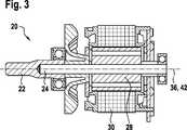
Die Elektromotoreinheit
Die tragbare Werkzeugmaschine
Die Elektromotoreinheit
Die Führungseinheit
Die tragbare Werkzeugmaschine
Das Motorgehäuse
Claims (10)
Translated fromGermanPriority Applications (2)
| Application Number | Priority Date | Filing Date | Title |
|---|---|---|---|
| DE102016218313.3ADE102016218313A1 (en) | 2016-09-23 | 2016-09-23 | Portable machine tool |
| PCT/EP2017/069033WO2018054583A1 (en) | 2016-09-23 | 2017-07-27 | Portable machine tool |
Applications Claiming Priority (1)
| Application Number | Priority Date | Filing Date | Title |
|---|---|---|---|
| DE102016218313.3ADE102016218313A1 (en) | 2016-09-23 | 2016-09-23 | Portable machine tool |
Publications (1)
| Publication Number | Publication Date |
|---|---|
| DE102016218313A1true DE102016218313A1 (en) | 2018-03-29 |
Family
ID=59520890
Family Applications (1)
| Application Number | Title | Priority Date | Filing Date |
|---|---|---|---|
| DE102016218313.3APendingDE102016218313A1 (en) | 2016-09-23 | 2016-09-23 | Portable machine tool |
Country Status (2)
| Country | Link |
|---|---|
| DE (1) | DE102016218313A1 (en) |
| WO (1) | WO2018054583A1 (en) |
Cited By (2)
| Publication number | Priority date | Publication date | Assignee | Title |
|---|---|---|---|---|
| CN112074372A (en)* | 2018-05-04 | 2020-12-11 | 罗伯特·博世有限公司 | Grinder housing |
| DE102022123061A1 (en)* | 2022-09-09 | 2024-03-14 | Andreas Stihl Ag & Co. Kg | wood trimmer |
Citations (5)
| Publication number | Priority date | Publication date | Assignee | Title |
|---|---|---|---|---|
| US2879814A (en) | 1957-05-21 | 1959-03-31 | Omark Industries Inc | Attachment for converting a portable circular saw to a chain saw |
| DE1910785U (en) | 1964-11-30 | 1965-02-25 | Solo Kleinmotoren G M B H | QUICK CONNECT COUPLING. |
| DE2542775A1 (en) | 1975-09-25 | 1977-03-31 | Kress Elektrik Gmbh & Co | CONNECTING DEVICE FOR MACHINE TOOLS |
| US4649644A (en) | 1985-06-07 | 1987-03-17 | Hudd Enterprises | Circular saw conversion adapter |
| US20070050992A1 (en) | 2005-09-06 | 2007-03-08 | Fisher David B | System and apparatus for attaching an electric motor to a power tool |
Family Cites Families (4)
| Publication number | Priority date | Publication date | Assignee | Title |
|---|---|---|---|---|
| DE20120984U1 (en)* | 2001-12-27 | 2002-04-11 | Trumpf Grüsch AG, Grüsch | Machine for the cutting processing of plate-like workpieces, in particular sandwich plates |
| DE102011005041A1 (en)* | 2011-03-03 | 2012-09-06 | Robert Bosch Gmbh | Portable machine tool |
| DE102012215450A1 (en)* | 2012-08-31 | 2014-03-06 | Robert Bosch Gmbh | Portable machine tool |
| DE102012215457A1 (en)* | 2012-08-31 | 2014-03-06 | Robert Bosch Gmbh | Machine tool, particularly portable machine tool for machine tool system for processing of workpiece, comprises drive unit arranged at distance to drive of machine tool separating device at coupling device, and drive direction reversal unit |
- 2016
- 2016-09-23DEDE102016218313.3Apatent/DE102016218313A1/enactivePending
- 2017
- 2017-07-27WOPCT/EP2017/069033patent/WO2018054583A1/ennot_activeCeased
Patent Citations (5)
| Publication number | Priority date | Publication date | Assignee | Title |
|---|---|---|---|---|
| US2879814A (en) | 1957-05-21 | 1959-03-31 | Omark Industries Inc | Attachment for converting a portable circular saw to a chain saw |
| DE1910785U (en) | 1964-11-30 | 1965-02-25 | Solo Kleinmotoren G M B H | QUICK CONNECT COUPLING. |
| DE2542775A1 (en) | 1975-09-25 | 1977-03-31 | Kress Elektrik Gmbh & Co | CONNECTING DEVICE FOR MACHINE TOOLS |
| US4649644A (en) | 1985-06-07 | 1987-03-17 | Hudd Enterprises | Circular saw conversion adapter |
| US20070050992A1 (en) | 2005-09-06 | 2007-03-08 | Fisher David B | System and apparatus for attaching an electric motor to a power tool |
Cited By (3)
| Publication number | Priority date | Publication date | Assignee | Title |
|---|---|---|---|---|
| CN112074372A (en)* | 2018-05-04 | 2020-12-11 | 罗伯特·博世有限公司 | Grinder housing |
| CN112074372B (en)* | 2018-05-04 | 2023-10-27 | 罗伯特·博世有限公司 | Grinding machine housing |
| DE102022123061A1 (en)* | 2022-09-09 | 2024-03-14 | Andreas Stihl Ag & Co. Kg | wood trimmer |
Also Published As
| Publication number | Publication date |
|---|---|
| WO2018054583A1 (en) | 2018-03-29 |
Similar Documents
| Publication | Publication Date | Title |
|---|---|---|
| EP2686148B1 (en) | Tool clamping device | |
| WO2014206620A1 (en) | Machining tool | |
| EP2680995B1 (en) | Portable machine tool | |
| EP2681014B1 (en) | Portable power tool | |
| EP3160694B1 (en) | Portable machine tool | |
| EP2681023B1 (en) | Machine tool separating device | |
| EP2681017A1 (en) | Machine tool system | |
| WO2012116829A1 (en) | Machine tool system | |
| DE102016218313A1 (en) | Portable machine tool | |
| WO2012116841A1 (en) | Power tool system | |
| DE102011005016A1 (en) | Machine tool separating device | |
| DE102012215455A1 (en) | Machine tool system | |
| EP2890524B1 (en) | Machine tool system | |
| DE102013202027A1 (en) | Portable power tool e.g. drilling and/or chisel hammer for machining workpiece, has battery pack receiving unit to cover battery pack receptacle that is provided in inner region of main handle or inner region of stirrup-shaped handle | |
| DE102012215450A1 (en) | Portable machine tool | |
| EP2890525A2 (en) | Power tool system | |
| EP2841244A1 (en) | Machine tool separating device | |
| DE102012215457A1 (en) | Machine tool, particularly portable machine tool for machine tool system for processing of workpiece, comprises drive unit arranged at distance to drive of machine tool separating device at coupling device, and drive direction reversal unit | |
| EP2700298A1 (en) | Garden tool insert device | |
| DE102011005042A1 (en) | Portable machine tool | |
| DE102016218314A1 (en) | Portable machine tool, in particular multifunctional machine tool | |
| DE102013220232B4 (en) | Portable machine tool with workpiece support unit | |
| EP2841241A1 (en) | Cutting unit segment | |
| WO2012116842A1 (en) | Portable power tool | |
| DE102013220237A1 (en) | Workpiece transfer device |
Legal Events
| Date | Code | Title | Description |
|---|---|---|---|
| R163 | Identified publications notified | ||
| R012 | Request for examination validly filed |