DE102016212527B4 - Blink unit for an exterior mirror - Google Patents
Blink unit for an exterior mirrorDownload PDFInfo
- Publication number
- DE102016212527B4 DE102016212527B4DE102016212527.3ADE102016212527ADE102016212527B4DE 102016212527 B4DE102016212527 B4DE 102016212527B4DE 102016212527 ADE102016212527 ADE 102016212527ADE 102016212527 B4DE102016212527 B4DE 102016212527B4
- Authority
- DE
- Germany
- Prior art keywords
- lens
- light source
- unit
- diaphragm
- film
- Prior art date
- Legal status (The legal status is an assumption and is not a legal conclusion. Google has not performed a legal analysis and makes no representation as to the accuracy of the status listed.)
- Active
Links
- 238000009434installationMethods0.000claimsabstractdescription3
- 230000015572biosynthetic processEffects0.000claimsdescription2
- 239000010408filmSubstances0.000description26
- 230000004397blinkingEffects0.000description6
- 239000011888foilSubstances0.000description6
- 230000003287optical effectEffects0.000description5
- 239000011248coating agentSubstances0.000description2
- 238000000576coating methodMethods0.000description2
- 239000012788optical filmSubstances0.000description2
- 230000008878couplingEffects0.000description1
- 238000010168coupling processMethods0.000description1
- 238000005859coupling reactionMethods0.000description1
- 230000000694effectsEffects0.000description1
- 230000003993interactionEffects0.000description1
- 238000004519manufacturing processMethods0.000description1
- 230000000873masking effectEffects0.000description1
- 239000011241protective layerSubstances0.000description1
Images

Classifications
- B—PERFORMING OPERATIONS; TRANSPORTING
- B60—VEHICLES IN GENERAL
- B60Q—ARRANGEMENT OF SIGNALLING OR LIGHTING DEVICES, THE MOUNTING OR SUPPORTING THEREOF OR CIRCUITS THEREFOR, FOR VEHICLES IN GENERAL
- B60Q1/00—Arrangement of optical signalling or lighting devices, the mounting or supporting thereof or circuits therefor
- B60Q1/26—Arrangement of optical signalling or lighting devices, the mounting or supporting thereof or circuits therefor the devices being primarily intended to indicate the vehicle, or parts thereof, or to give signals, to other traffic
- B60Q1/2661—Arrangement of optical signalling or lighting devices, the mounting or supporting thereof or circuits therefor the devices being primarily intended to indicate the vehicle, or parts thereof, or to give signals, to other traffic mounted on parts having other functions
- B60Q1/2665—Arrangement of optical signalling or lighting devices, the mounting or supporting thereof or circuits therefor the devices being primarily intended to indicate the vehicle, or parts thereof, or to give signals, to other traffic mounted on parts having other functions on rear-view mirrors
- B—PERFORMING OPERATIONS; TRANSPORTING
- B60—VEHICLES IN GENERAL
- B60Q—ARRANGEMENT OF SIGNALLING OR LIGHTING DEVICES, THE MOUNTING OR SUPPORTING THEREOF OR CIRCUITS THEREFOR, FOR VEHICLES IN GENERAL
- B60Q1/00—Arrangement of optical signalling or lighting devices, the mounting or supporting thereof or circuits therefor
- B60Q1/26—Arrangement of optical signalling or lighting devices, the mounting or supporting thereof or circuits therefor the devices being primarily intended to indicate the vehicle, or parts thereof, or to give signals, to other traffic
- B60Q1/28—Arrangement of optical signalling or lighting devices, the mounting or supporting thereof or circuits therefor the devices being primarily intended to indicate the vehicle, or parts thereof, or to give signals, to other traffic for indicating front of vehicle
- B—PERFORMING OPERATIONS; TRANSPORTING
- B60—VEHICLES IN GENERAL
- B60Q—ARRANGEMENT OF SIGNALLING OR LIGHTING DEVICES, THE MOUNTING OR SUPPORTING THEREOF OR CIRCUITS THEREFOR, FOR VEHICLES IN GENERAL
- B60Q1/00—Arrangement of optical signalling or lighting devices, the mounting or supporting thereof or circuits therefor
- B60Q1/26—Arrangement of optical signalling or lighting devices, the mounting or supporting thereof or circuits therefor the devices being primarily intended to indicate the vehicle, or parts thereof, or to give signals, to other traffic
- B60Q1/34—Arrangement of optical signalling or lighting devices, the mounting or supporting thereof or circuits therefor the devices being primarily intended to indicate the vehicle, or parts thereof, or to give signals, to other traffic for indicating change of drive direction
- B—PERFORMING OPERATIONS; TRANSPORTING
- B60—VEHICLES IN GENERAL
- B60R—VEHICLES, VEHICLE FITTINGS, OR VEHICLE PARTS, NOT OTHERWISE PROVIDED FOR
- B60R1/00—Optical viewing arrangements; Real-time viewing arrangements for drivers or passengers using optical image capturing systems, e.g. cameras or video systems specially adapted for use in or on vehicles
- B60R1/02—Rear-view mirror arrangements
- B60R1/06—Rear-view mirror arrangements mounted on vehicle exterior
- B—PERFORMING OPERATIONS; TRANSPORTING
- B60—VEHICLES IN GENERAL
- B60R—VEHICLES, VEHICLE FITTINGS, OR VEHICLE PARTS, NOT OTHERWISE PROVIDED FOR
- B60R1/00—Optical viewing arrangements; Real-time viewing arrangements for drivers or passengers using optical image capturing systems, e.g. cameras or video systems specially adapted for use in or on vehicles
- B60R1/12—Mirror assemblies combined with other articles, e.g. clocks
- B60R1/1207—Mirror assemblies combined with other articles, e.g. clocks with lamps; with turn indicators
- F—MECHANICAL ENGINEERING; LIGHTING; HEATING; WEAPONS; BLASTING
- F21—LIGHTING
- F21S—NON-PORTABLE LIGHTING DEVICES; SYSTEMS THEREOF; VEHICLE LIGHTING DEVICES SPECIALLY ADAPTED FOR VEHICLE EXTERIORS
- F21S43/00—Signalling devices specially adapted for vehicle exteriors, e.g. brake lamps, direction indicator lights or reversing lights
- F21S43/20—Signalling devices specially adapted for vehicle exteriors, e.g. brake lamps, direction indicator lights or reversing lights characterised by refractors, transparent cover plates, light guides or filters
- F21S43/235—Light guides
- F21S43/236—Light guides characterised by the shape of the light guide
- F21S43/237—Light guides characterised by the shape of the light guide rod-shaped
- F—MECHANICAL ENGINEERING; LIGHTING; HEATING; WEAPONS; BLASTING
- F21—LIGHTING
- F21S—NON-PORTABLE LIGHTING DEVICES; SYSTEMS THEREOF; VEHICLE LIGHTING DEVICES SPECIALLY ADAPTED FOR VEHICLE EXTERIORS
- F21S43/00—Signalling devices specially adapted for vehicle exteriors, e.g. brake lamps, direction indicator lights or reversing lights
- F21S43/20—Signalling devices specially adapted for vehicle exteriors, e.g. brake lamps, direction indicator lights or reversing lights characterised by refractors, transparent cover plates, light guides or filters
- F21S43/235—Light guides
- F21S43/242—Light guides characterised by the emission area
- F21S43/245—Light guides characterised by the emission area emitting light from one or more of its major surfaces
- F—MECHANICAL ENGINEERING; LIGHTING; HEATING; WEAPONS; BLASTING
- F21—LIGHTING
- F21S—NON-PORTABLE LIGHTING DEVICES; SYSTEMS THEREOF; VEHICLE LIGHTING DEVICES SPECIALLY ADAPTED FOR VEHICLE EXTERIORS
- F21S43/00—Signalling devices specially adapted for vehicle exteriors, e.g. brake lamps, direction indicator lights or reversing lights
- F21S43/20—Signalling devices specially adapted for vehicle exteriors, e.g. brake lamps, direction indicator lights or reversing lights characterised by refractors, transparent cover plates, light guides or filters
- F21S43/235—Light guides
- F21S43/247—Light guides with a single light source being coupled into the light guide
- F—MECHANICAL ENGINEERING; LIGHTING; HEATING; WEAPONS; BLASTING
- F21—LIGHTING
- F21S—NON-PORTABLE LIGHTING DEVICES; SYSTEMS THEREOF; VEHICLE LIGHTING DEVICES SPECIALLY ADAPTED FOR VEHICLE EXTERIORS
- F21S43/00—Signalling devices specially adapted for vehicle exteriors, e.g. brake lamps, direction indicator lights or reversing lights
- F21S43/20—Signalling devices specially adapted for vehicle exteriors, e.g. brake lamps, direction indicator lights or reversing lights characterised by refractors, transparent cover plates, light guides or filters
- F21S43/255—Filters
- F—MECHANICAL ENGINEERING; LIGHTING; HEATING; WEAPONS; BLASTING
- F21—LIGHTING
- F21S—NON-PORTABLE LIGHTING DEVICES; SYSTEMS THEREOF; VEHICLE LIGHTING DEVICES SPECIALLY ADAPTED FOR VEHICLE EXTERIORS
- F21S43/00—Signalling devices specially adapted for vehicle exteriors, e.g. brake lamps, direction indicator lights or reversing lights
- F21S43/20—Signalling devices specially adapted for vehicle exteriors, e.g. brake lamps, direction indicator lights or reversing lights characterised by refractors, transparent cover plates, light guides or filters
- F21S43/26—Refractors, transparent cover plates, light guides or filters not provided in groups F21S43/235 - F21S43/255
- F—MECHANICAL ENGINEERING; LIGHTING; HEATING; WEAPONS; BLASTING
- F21—LIGHTING
- F21S—NON-PORTABLE LIGHTING DEVICES; SYSTEMS THEREOF; VEHICLE LIGHTING DEVICES SPECIALLY ADAPTED FOR VEHICLE EXTERIORS
- F21S43/00—Signalling devices specially adapted for vehicle exteriors, e.g. brake lamps, direction indicator lights or reversing lights
- F21S43/20—Signalling devices specially adapted for vehicle exteriors, e.g. brake lamps, direction indicator lights or reversing lights characterised by refractors, transparent cover plates, light guides or filters
- F21S43/27—Attachment thereof
- F—MECHANICAL ENGINEERING; LIGHTING; HEATING; WEAPONS; BLASTING
- F21—LIGHTING
- F21V—FUNCTIONAL FEATURES OR DETAILS OF LIGHTING DEVICES OR SYSTEMS THEREOF; STRUCTURAL COMBINATIONS OF LIGHTING DEVICES WITH OTHER ARTICLES, NOT OTHERWISE PROVIDED FOR
- F21V17/00—Fastening of component parts of lighting devices, e.g. shades, globes, refractors, reflectors, filters, screens, grids or protective cages
- F21V17/10—Fastening of component parts of lighting devices, e.g. shades, globes, refractors, reflectors, filters, screens, grids or protective cages characterised by specific fastening means or way of fastening
- F21V17/16—Fastening of component parts of lighting devices, e.g. shades, globes, refractors, reflectors, filters, screens, grids or protective cages characterised by specific fastening means or way of fastening by deformation of parts; Snap action mounting
- F21V17/162—Fastening of component parts of lighting devices, e.g. shades, globes, refractors, reflectors, filters, screens, grids or protective cages characterised by specific fastening means or way of fastening by deformation of parts; Snap action mounting the parts being subjected to traction or compression, e.g. coil springs
- B—PERFORMING OPERATIONS; TRANSPORTING
- B60—VEHICLES IN GENERAL
- B60R—VEHICLES, VEHICLE FITTINGS, OR VEHICLE PARTS, NOT OTHERWISE PROVIDED FOR
- B60R13/00—Elements for body-finishing, identifying, or decorating; Arrangements or adaptations for advertising purposes
- B60R13/005—Manufacturers' emblems, name plates, bonnet ornaments, mascots or the like; Mounting means therefor
- F—MECHANICAL ENGINEERING; LIGHTING; HEATING; WEAPONS; BLASTING
- F21—LIGHTING
- F21S—NON-PORTABLE LIGHTING DEVICES; SYSTEMS THEREOF; VEHICLE LIGHTING DEVICES SPECIALLY ADAPTED FOR VEHICLE EXTERIORS
- F21S43/00—Signalling devices specially adapted for vehicle exteriors, e.g. brake lamps, direction indicator lights or reversing lights
- F21S43/20—Signalling devices specially adapted for vehicle exteriors, e.g. brake lamps, direction indicator lights or reversing lights characterised by refractors, transparent cover plates, light guides or filters
- F21S43/2605—Refractors
- F21S43/2641—Refractors or refracting portions characterised by their relative arrangement, e.g. parallel refractors
- F21S43/26411—Two or more successive refractors
- F—MECHANICAL ENGINEERING; LIGHTING; HEATING; WEAPONS; BLASTING
- F21—LIGHTING
- F21W—INDEXING SCHEME ASSOCIATED WITH SUBCLASSES F21K, F21L, F21S and F21V, RELATING TO USES OR APPLICATIONS OF LIGHTING DEVICES OR SYSTEMS
- F21W2103/00—Exterior vehicle lighting devices for signalling purposes
- F21W2103/20—Direction indicator lights
Landscapes
- Engineering & Computer Science (AREA)
- General Engineering & Computer Science (AREA)
- Mechanical Engineering (AREA)
- Multimedia (AREA)
- Lighting Device Outwards From Vehicle And Optical Signal (AREA)
Abstract
Translated fromGerman
Description
Translated fromGermanGebiet der ErfindungField of the invention
Die vorliegende Erfindung betrifft eine Blinkeinheit für einen Außenspiegel für ein Kraftfahrzeug, wobei die Blinkeinheit dazu eingerichtet ist, ein Blinklicht in Einbaulage der Blinkeinheit und des Außenspiegels in Fahrtrichtung nach vorne abzustrahlen und betrifft einen Außenspiegel umfassend eine solche Blinkeinheit.The present invention relates to a flashing unit for a wing mirror for a motor vehicle, wherein the flashing unit is adapted to emit a flashing light in the installed position of the Blink unit and the outside mirror in the direction of travel forward and relates to an exterior mirror comprising such a flashing unit.
Stand der TechnikState of the art
Außenspiegel, die eine Blinkeinheit umfassen, sind an sich bekannt. Diese sind als zusätzliche Blinkeinrichtung in Kraftfahrzeugen zunehmend beliebt und erhöhen einerseits die Sicherheit des Fahrzeugs und werten andererseits das Fahrzeug ästhetisch auf.Exterior mirrors, which include a blink unit, are known per se. These are becoming increasingly popular as an additional flashing device in motor vehicles and, on the one hand, increase the safety of the vehicle and, on the other hand, enhance the aesthetics of the vehicle.
Verschiedene Ausführungsformen von Außenspiegeln mit integrierten Blinkern sind beispielsweise aus der
Aus der
Aus der
Zusammenfassung der ErfindungSummary of the invention
Es ist eine Aufgabe der Erfindung, eine Blinkeinheit für einen Außenspiegel für ein Kraftfahrzeug anzugeben, wobei das optische Design der Blinkeinheit einfach und kostengünstig für verschiedene Fahrzeugtypen oder verschiedene Fahrzeuge veränderbar ist.It is an object of the invention to provide a flashing unit for an exterior mirror for a motor vehicle, wherein the optical design of the Blink unit is easy and inexpensive for different vehicle types or different vehicles changeable.
Die Lösung der Aufgabe erfolgt durch eine Blinkeinheit für einen Außenspiegel für ein Kraftfahrzeug, wobei die Blinkeinheit dazu eingerichtet ist, ein Blinklicht in Einbaulage in Fahrtrichtung nach vorne abzustrahlen, wobei die Blinkeinheit eine Lichtquelle umfasst und eine vor der Lichtquelle angeordnete Linse, wobei im Raum zwischen der Lichtquelle und der Linse eine Folie mit abwechselnd lichtdurchlässigen und nicht-lichtdurchlässigen Strukturen angeordnet ist, und wobei die Blinkeinheit weiterhin einen Gehäuseboden hinter der Lichtquelle und eine Blende zwischen Lichtquelle und Linse umfasst, und wobei die Folie entweder zwischen der Blende und der Linse angeordnet und von der Blende und der Linse geklemmt, oder die Folie zwischen der Blende und Lichtquelle angeordnet und vom Gehäuseboden und der Blende geklemmt ist.The object is achieved by a flashing unit for an exterior mirror for a motor vehicle, wherein the flashing unit is adapted to emit a flashing light in installation position forward in the direction of travel, wherein the flashing unit comprises a light source and arranged in front of the light source lens, wherein in space between the light source and the lens, a film having alternately transparent and non-translucent structures is arranged, and wherein the Blink unit further comprises a housing bottom behind the light source and a diaphragm between the light source and the lens, and wherein the film disposed either between the diaphragm and the lens and clamped by the diaphragm and the lens, or the film between the diaphragm and light source is arranged and clamped by the housing bottom and the diaphragm.
„Vorne“ heißt dabei erfindungsgemäß in Leuchtrichtung und damit auch in Fahrtrichtung des Kraftfahrzeuges vorne - entsprechend bezeichnet „hinten“ die umgekehrte Richtung, also der Leuchtrichtung des Blinkers entgegengesetzt."Front" means according to the invention in the direction of light and thus also in the direction of travel of the motor vehicle front - correspondingly referred to "back" the opposite direction, ie opposite to the direction of the direction of the turn signal.
Erfindungsgemäß ist zwischen der Lichtquelle und der Linse, die bevorzugt die äußere Begrenzung der Blinkeinheit bildet, eine Folie angeordnet und durch Klemmen befestigt. Die Folie trägt abwechselnd lichtdurchlässige und nicht-lichtdurchlässige Strukturen, also strukturierte Abschnitte, so dass sie das beim Blinken austretende Licht strukturiert und beispielsweise Muster, Styles, Beschriftungen, Logos und ähnliches gestalten kann.According to the invention, a film is arranged between the light source and the lens, which preferably forms the outer boundary of the blinking unit, and fixed by clamping. The film alternately supports translucent and non-translucent structures, ie structured sections, so that it can structure the light emerging during flashing and, for example, design patterns, styles, inscriptions, logos and the like.
Die Folie ist geklemmt und bevorzugt nicht auf sonstige Weise in der Blinkeinheit befestigt, insbesondere nicht geklebt oder umspritzt, so dass die Folie einfach austauschbar ist.The film is clamped and preferably not otherwise secured in the blinking unit, in particular not glued or overmolded, so that the foil is easily replaceable.
Hierdurch kann das optische Design der Blinkeinheit auf einfachste Weise und kostengünstig für verschiedene Fahrzeugtypen oder Fahrzeuge bei deren Herstellung oder je nach Ausführung auch danach durch Austauschen der Folie geändert werden.As a result, the optical design of the Blink unit can be easily and inexpensively changed for different types of vehicles or vehicles during their manufacture or, depending on the design, thereafter by replacing the film.
Die abwechselnd lichtdurchlässigen und nicht-lichtdurchlässigen Strukturen der Folie bilden bevorzugt ein Muster, insbesondere ein optisch ansprechendes Design, eine Beschriftung und/oder ein Logo.The alternately translucent and non-translucent structures of the film preferably form a pattern, in particular a visually appealing design, a label and / or a logo.
Die Blinkeinheit umfasst eine Blende zwischen Lichtquelle und Linse. Die Folie kann dann von der Blende und der Linse geklemmt sein, also zwischen Blende und Linse eingeklemmt sein. Blende und Linse können annähernd gleiche Größe haben.The Blink unit comprises a shutter between the light source and the lens. The film can then be clamped by the diaphragm and the lens, that is to be clamped between the diaphragm and the lens. Aperture and lens can be approximately the same size.
Die Blinkeinheit umfasst weiterhin einen Gehäuseboden hinter der Lichtquelle. Die Folie kann vom Gehäuseboden und der Linse geklemmt sein. Der Gehäuseboden kann ebenfalls eine ähnliche Größe wie die Linse aufweisen und kann bevorzugt etwas größer als die Linse sein und die Linse halten und/oder als Rahmen aufnehmen.The blinking unit further comprises a housing bottom behind the light source. The film may be clamped by the housing bottom and the lens. The housing bottom may also have a similar size to the lens and may preferably be slightly larger than the lens and hold the lens and / or receive as a frame.
Des Weiteren kann die Folie vom Gehäuseboden und der Blende geklemmt sein. Eine Klemmwirkung kann auch durch Gehäuseboden, Blende und Linse gemeinsam erreicht werden.Furthermore, the film may be clamped by the housing bottom and the panel. A clamping effect can also be achieved by housing bottom, aperture and lens together.
Vorzugsweise weist der Gehäuseboden und/oder die Blende und/oder die Linse zumindest eine Ausformung auf, die dazu ausgebildet ist, die Folie rutschsicher einzuklemmen, insbesondere einen Flansch, der parallel zur Folie ausgerichtet sein kann, oder ein Federelement oder ein Nutelement. Die Folie kann dadurch insbesondere zwischen zwei Flanschflächen und/oder zwischen Nut und Feder Elementen geklemmt sein.Preferably, the housing bottom and / or the diaphragm and / or the lens has at least one formation which is designed to clamp the film non-slip, in particular a flange which can be aligned parallel to the film, or a spring element or a groove element. The film can be clamped in particular between two flange surfaces and / or between tongue and groove elements.
Die Lichtquelle der Blinkeinheit kann bevorzugt durch einen Lichtleiter und/oder durch LEDs gebildet sein.The light source of the blinking unit may preferably be formed by a light guide and / or by LEDs.
Die Linse kann auch nach Befestigung der Folie dauerhaft befestigt, insbesondere verschweißt sein mit dem Gehäuse.The lens can be permanently attached even after attachment of the film, in particular welded to the housing.
Es können auch mehrere Folien in einer erfindungsgemäßen Blinkeinheit verwendet werden, bevorzugt alle Folien geklemmt.It is also possible to use a plurality of films in a blinking unit according to the invention, preferably clamping all the films.
Ein erfindungsgemäßer Außenspiegel für ein Kraftfahrzeug umfasst eine Blinkeinheit wie oben beschrieben. Bei einem verbauten Außenspiegel ist die Blinkeinheit so im Außenspiegel angeordnet, dass das Blinklicht im Wesentlichen in Fahrtrichtung nach vorne abgestrahlt wird, und dabei die geklemmte Folie mit lichtdurchlässigen und nicht-lichtdurchlässigen Strukturen passiert. Die Folie wirkt als Maskierung für das Blinklicht, um das nach vorne strahlende Leuchtfeld des Blinkers mit optischen Strukturen, wie Mustern, Beschriftungen oder Logos, zu verbinden. Die optischen Strukturen sind bevorzugt nur sichtbar, oder nur deutlich sichtbar, wenn der Blinker aktiv ist.An inventive exterior mirror for a motor vehicle comprises a blinking unit as described above. In the case of a built-in outside mirror, the flashing unit is arranged in the outside mirror such that the flashing light is radiated forward substantially in the direction of travel, thereby passing the clamped film with translucent and non-translucent structures. The film acts as a masking light for the flashing light to connect the forwardly illuminated field of the turn signal with optical structures, such as patterns, labels or logos. The optical structures are preferably only visible, or only clearly visible when the turn signal is active.
Figurenlistelist of figures
Die Erfindung wird im Folgenden beispielhaft unter Bezugnahme auf die Zeichnungen beschrieben.
1 ist eine Explosionsdarstellung einer erfindungsgemäßen Blinkeinheit für einen Außenspiegel.2 ist eine Schnittansicht einer erfindungsgemäßen Blinkeinheit in einer weiteren Ausführungsform.3 ist eine Schnittansicht einer erfindungsgemäßen Blinkeinheit in einer weiteren Ausführungsform.
1 is an exploded view of a Blink unit according to the invention for an exterior mirror.2 is a sectional view of a Blink unit according to the invention in a further embodiment.3 is a sectional view of a Blink unit according to the invention in a further embodiment.
Detaillierte Beschreibung der ErfindungDetailed description of the invention
In
Die Folie
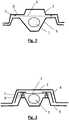
Dabei ist in
Die in
Selbstverständlich kann die Folie
BezugszeichenlisteLIST OF REFERENCE NUMBERS
- 11
- Lichtquellelight source
- 22
- Linselens
- 33
- Foliefoil
- 44
- Blendecover
- 55
- Gehäusebodencaseback
- 66
- Flanschflange
- 77
- Federelementspring element
- 88th
- Nutelementgroove element
- 99
- Steuereinheitcontrol unit
Claims (5)
Translated fromGermanPriority Applications (3)
| Application Number | Priority Date | Filing Date | Title |
|---|---|---|---|
| DE102016212527.3ADE102016212527B4 (en) | 2016-07-08 | 2016-07-08 | Blink unit for an exterior mirror |
| US15/642,750US10173581B2 (en) | 2016-07-08 | 2017-07-06 | Turn signal unit for an external mirror |
| US16/240,116US10661705B2 (en) | 2016-07-08 | 2019-01-04 | Exterior rearview mirror with turn signal unit |
Applications Claiming Priority (1)
| Application Number | Priority Date | Filing Date | Title |
|---|---|---|---|
| DE102016212527.3ADE102016212527B4 (en) | 2016-07-08 | 2016-07-08 | Blink unit for an exterior mirror |
Publications (2)
| Publication Number | Publication Date |
|---|---|
| DE102016212527A1 DE102016212527A1 (en) | 2018-01-11 |
| DE102016212527B4true DE102016212527B4 (en) | 2019-08-08 |
Family
ID=60676537
Family Applications (1)
| Application Number | Title | Priority Date | Filing Date |
|---|---|---|---|
| DE102016212527.3AActiveDE102016212527B4 (en) | 2016-07-08 | 2016-07-08 | Blink unit for an exterior mirror |
Country Status (2)
| Country | Link |
|---|---|
| US (2) | US10173581B2 (en) |
| DE (1) | DE102016212527B4 (en) |
Families Citing this family (6)
| Publication number | Priority date | Publication date | Assignee | Title |
|---|---|---|---|---|
| US8333492B2 (en) | 2007-05-03 | 2012-12-18 | Donnelly Corporation | Illumination module for a vehicle |
| DE102016212527B4 (en) | 2016-07-08 | 2019-08-08 | Magna Mirrors Holding Gmbh | Blink unit for an exterior mirror |
| DE102018115693A1 (en)* | 2018-06-28 | 2020-01-02 | Motherson Innovations Company Limited | Process for producing a turn signal module and turn signal module, rear-view device and motor vehicle |
| DE102019210283A1 (en) | 2018-08-13 | 2020-02-13 | Magna Mirrors Holding Gmbh | Exterior rear-view mirror arrangement with integrated battery charge indicator function |
| DE102018221145A1 (en)* | 2018-12-06 | 2020-06-10 | Volkswagen Aktiengesellschaft | Lighting device for a vehicle |
| WO2021038082A1 (en)* | 2019-08-30 | 2021-03-04 | Motherson Innovations Company Ltd. | Light assembly, vehicle design element, rear view device and door finisher |
Citations (6)
| Publication number | Priority date | Publication date | Assignee | Title |
|---|---|---|---|---|
| DE10043101A1 (en) | 2000-09-01 | 2002-03-28 | Volkswagen Ag | External vehicle mirror with integral drive direction indicator using foil doped with particles which do not transmit light |
| DE102006035842A1 (en)* | 2005-09-09 | 2007-03-22 | Fer Fahrzeugelektrik Gmbh | Vehicle lamp e.g. side blinking lamp, for use in cap of external rear mirror, has integrally formed optical fiber-blind unit that includes optical fiber and blind section, where unit is manufactured by two-component spray casting process |
| US20070279923A1 (en) | 2000-07-12 | 2007-12-06 | Alejandro Rodriguez Barros | Rear-View Side Mirror For A Vehicle |
| JP2010254056A (en)* | 2009-04-23 | 2010-11-11 | Stanley Electric Co Ltd | LED lamp for vehicle |
| DE102011103200A1 (en) | 2011-05-31 | 2012-12-06 | SMR Patents S.à.r.l. | Light window for use as light conductor for turn indicator in outside mirror arrangement of vehicle, has uncoupling structures at certain location of window, and optical film with molded coating and provided with uncoupling structures |
| DE102014106081A1 (en)* | 2013-05-03 | 2014-11-06 | Ford Global Technologies, Llc | Vehicle headlamp assembly |
Family Cites Families (113)
| Publication number | Priority date | Publication date | Assignee | Title |
|---|---|---|---|---|
| US4041301A (en) | 1976-03-24 | 1977-08-09 | General Motors Corporation | Key illuminating door handle |
| IT1208146B (en) | 1986-12-10 | 1989-06-06 | Raciti Maurizio | COURTESY AND SIGNALING DOUBLE CEILING LIGHT DOOR OPEN VEHICLE |
| US4788630A (en) | 1987-07-10 | 1988-11-29 | Irvin Industries, Inc. | Illumination for vehicle accessories |
| US5040103A (en) | 1990-03-19 | 1991-08-13 | Whelen Technologies, Inc. | Light assembly for wide area illumination |
| US5233375A (en) | 1991-07-29 | 1993-08-03 | Williams Charles A | Logo projector |
| US5297010A (en) | 1992-08-28 | 1994-03-22 | Itc Incorporated | Illuminated grab handle |
| US5371659A (en) | 1993-02-01 | 1994-12-06 | Donnelly Corporation | Remote-actuated exterior vehicle security light |
| US6276821B1 (en) | 1992-12-16 | 2001-08-21 | Donnelly Corporation | Vehicle exterior mirror system with signal light |
| US5497306A (en) | 1993-02-01 | 1996-03-05 | Donnelly Corporation | Exterior vehicle security light |
| US5823654A (en) | 1993-02-01 | 1998-10-20 | Donnelly Corporation | Universal exterior vehicle security light |
| US5669699A (en) | 1994-11-02 | 1997-09-23 | Donnelly Corporation | Exterior vehicle security light |
| US5587699A (en)* | 1994-11-03 | 1996-12-24 | United Technologies Automotive Systems Inc. | Exterior mirror with information display |
| US5581230A (en) | 1995-01-05 | 1996-12-03 | Amerisafe Corporation | Illuminated door handle assembly |
| US5499169A (en) | 1995-05-16 | 1996-03-12 | Chen; Chun-Ming | Rearview mirror lamp circuit assembly |
| JPH09303477A (en)* | 1996-05-16 | 1997-11-25 | Nissan Motor Co Ltd | Active noise and vibration control device |
| US5815018A (en) | 1996-07-16 | 1998-09-29 | Systech Solutions, Inc. | Pulse modulator circuit for an illuminator system |
| DE19631869A1 (en) | 1996-08-07 | 1998-02-12 | Bosch Gmbh Robert | Motor vehicle door lock or the like |
| JPH10159419A (en) | 1996-11-29 | 1998-06-16 | Aisin Seiki Co Ltd | Automatic door lock control device |
| US6356376B1 (en) | 1997-04-02 | 2002-03-12 | Gentex Corporation | Electrochromic rearview mirror incorporating a third surface metal reflector and a display/signal light |
| JPH10292702A (en) | 1997-04-21 | 1998-11-04 | Aisin Seiki Co Ltd | Door proximity communication device and door lock control device |
| US6070998A (en) | 1998-01-23 | 2000-06-06 | General Motors Corporation | Fiber optic lighting system for vehicle door handle |
| US6152590A (en) | 1998-02-13 | 2000-11-28 | Donnelly Hohe Gmbh & Co. Kg | Lighting device for motor vehicles |
| US6158869A (en) | 1998-05-13 | 2000-12-12 | Top Source Technology, Inc. | Puddle and footwell lighting integrated into a speaker grille |
| DE19828253B4 (en)* | 1998-06-25 | 2006-04-06 | Daimlerchrysler Ag | Exterior rear view mirror |
| DE19835155A1 (en) | 1998-08-04 | 2000-02-24 | Bosch Gmbh Robert | Device and method for an authorization request in a motor vehicle |
| GB2341365A (en) | 1998-09-09 | 2000-03-15 | Britax Wingard Ltd | Exterior rear view mirror with light |
| GB2342212B (en) | 1998-09-30 | 2002-12-24 | Delphi Automotive Systems Gmbh | Image projector for a motor vehicle |
| US6273579B1 (en) | 1999-02-12 | 2001-08-14 | Katie Holloway | Illuminated article for a door having a handle |
| US6572250B1 (en) | 1999-03-15 | 2003-06-03 | Britax Wingard Limited | Exterior mirror having an attachment member including an approach light |
| US6049271A (en) | 1999-06-29 | 2000-04-11 | Chu; Ching-Ti | Vehicle rearview mirror with multiple signal means |
| US7064882B2 (en)* | 2002-09-30 | 2006-06-20 | Gentex Corporation | Electrochromic devices having no positional offset between substrates |
| EP1083285A1 (en) | 1999-09-07 | 2001-03-14 | Robert Bosch Gmbh | Vehicle door locking system |
| EP1292931B1 (en) | 2000-02-11 | 2013-04-03 | SMR Patents S.à.r.l. | Exterior mirror |
| AU2001243285A1 (en) | 2000-03-02 | 2001-09-12 | Donnelly Corporation | Video mirror systems incorporating an accessory module |
| US6315419B1 (en) | 2000-04-24 | 2001-11-13 | George Erhardt Platzer, Jr. | Automotive rearview mirror having a main viewing section and an auxiliary blindzone-viewing section |
| US6623124B2 (en) | 2000-05-16 | 2003-09-23 | Hal Corporation | Projection type illuminating device |
| DE10025810B4 (en) | 2000-05-24 | 2014-01-23 | SMR Patents S.à.r.l. | Luminaire unit, in particular for exterior rearview mirrors of vehicles, preferably motor vehicles |
| JP3509790B2 (en) | 2000-08-09 | 2004-03-22 | アイシン精機株式会社 | Vehicle door lock device |
| US6416209B1 (en) | 2000-08-10 | 2002-07-09 | Daimlerchrysler Corporation | Exterior courtesy lighting/fender mounted |
| DE10045171A1 (en) | 2000-09-13 | 2002-03-28 | Itw Ateco Gmbh | Actuator for automobile door, includes stripe of electroluminescence sheet attached to surface of bow-like handle portion and connected to electric source |
| DE10051055A1 (en) | 2000-10-14 | 2002-05-02 | Bosch Gmbh Robert | Device for initiating an opening and locking process of a motor vehicle |
| WO2002041276A2 (en) | 2000-11-15 | 2002-05-23 | Snowy Village, Inc. | Led warning light and communication system |
| US7581859B2 (en)* | 2005-09-14 | 2009-09-01 | Donnelly Corp. | Display device for exterior rearview mirror |
| US7255451B2 (en) | 2002-09-20 | 2007-08-14 | Donnelly Corporation | Electro-optic mirror cell |
| ES2305163T3 (en) | 2001-08-16 | 2008-11-01 | Valeo Sicurezza Abitacolo S.P.A. | OPENING HANDLE THAT INCLUDES AN ELECTRONIC MODULE, ESPECIALLY FOR AUTOMOBILE VEHICLE. |
| US6779372B2 (en) | 2001-10-16 | 2004-08-24 | Robert Bosch Gmbh | Motor vehicle door lock with a lock unit and a control unit which are separate from one another |
| DE10212794A1 (en) | 2001-12-12 | 2003-06-26 | Witte Velbert Gmbh & Co Kg | Plastic injection molded component, e.g. a vehicle door handle, comprises a pre-finished module which holds electrical components and which is surrounded by a soft plastic mantle |
| US6523888B1 (en) | 2002-01-04 | 2003-02-25 | Honda Giken Kogyo Kabushiki Kaisha | Integrated light and grab rail assembly |
| US6796690B2 (en) | 2002-03-14 | 2004-09-28 | The Boeing Company | LED light source |
| US6926431B1 (en) | 2002-04-09 | 2005-08-09 | Magna Donnelly Mirrors North America, L.L.C. | Vehicular mirror assembly incorporating multifunctional illumination source |
| JP2004003152A (en) | 2002-05-31 | 2004-01-08 | Fuji Heavy Ind Ltd | Keyless entry device for vehicles |
| US20060061008A1 (en)* | 2004-09-14 | 2006-03-23 | Lee Karner | Mounting assembly for vehicle interior mirror |
| JP3901034B2 (en) | 2002-06-24 | 2007-04-04 | アイシン精機株式会社 | Vehicle door opening and closing device |
| US10144353B2 (en)* | 2002-08-21 | 2018-12-04 | Magna Electronics Inc. | Multi-camera vision system for a vehicle |
| US6919796B2 (en) | 2002-09-12 | 2005-07-19 | Magna Donnelly Mirrors North America, Llc | Dimming mirror with blind zone sub-mirror and indicator |
| JP4142378B2 (en) | 2002-09-19 | 2008-09-03 | 株式会社アルファ | Vehicle door locking / unlocking control system |
| WO2004026633A2 (en) | 2002-09-20 | 2004-04-01 | Donnelly Corporation | Mirror reflective element assembly |
| WO2004103772A2 (en) | 2003-05-19 | 2004-12-02 | Donnelly Corporation | Mirror assembly for vehicle |
| JP3913661B2 (en) | 2002-10-09 | 2007-05-09 | 本田技研工業株式会社 | Automatic door lock locking and unlocking device for vehicles |
| US6793385B2 (en) | 2002-11-07 | 2004-09-21 | Lear Corporation | Assist handle with integrated light unit |
| US7210798B2 (en) | 2003-01-17 | 2007-05-01 | High End Systems Inc. | Image projection lighting device and control system |
| US7097312B2 (en) | 2003-02-21 | 2006-08-29 | George E. Platzer, Jr. | Compound automotive rearview mirror |
| DE102004015544B4 (en) | 2003-03-31 | 2009-05-07 | Toyoda Gosei Co., Ltd. | LED light and side mirror device |
| JP3948431B2 (en)* | 2003-04-09 | 2007-07-25 | トヨタ自動車株式会社 | Vehicle periphery monitoring device |
| US7210820B2 (en) | 2003-05-07 | 2007-05-01 | Resonetics, Inc. | Methods and apparatuses for homogenizing light |
| TWM246202U (en) | 2003-05-20 | 2004-10-11 | Exon Science Inc | Vehicular door handle module |
| DE10331349B4 (en) | 2003-07-11 | 2009-05-28 | Daimler Ag | Motor vehicle headlamps |
| KR20050024648A (en) | 2003-09-01 | 2005-03-11 | 현대자동차주식회사 | Emitting Apparatus Indicating Location of Door Outside Handle |
| DE10341402A1 (en) | 2003-09-05 | 2005-04-07 | Brose Schließsysteme GmbH & Co.KG | Motor vehicle door locking system and inside door handle |
| WO2005035308A1 (en) | 2003-10-18 | 2005-04-21 | Daimlerchrysler Ag | Illumination device for a vehicle |
| US20050117364A1 (en) | 2003-10-27 | 2005-06-02 | Mark Rennick | Method and apparatus for projecting a turn signal indication |
| US7121688B2 (en) | 2004-03-01 | 2006-10-17 | Rempel Lee W | Box light |
| US7175321B1 (en) | 2004-03-24 | 2007-02-13 | Lopez Gustavo M | Projector systems |
| JP4257601B2 (en) | 2004-06-24 | 2009-04-22 | アイシン精機株式会社 | Vehicle door opening and closing device |
| DE102004038569B3 (en) | 2004-08-06 | 2005-10-20 | Huf Huelsbeck & Fuerst Gmbh | An automobile door handle |
| JP2006138129A (en) | 2004-11-12 | 2006-06-01 | Toyoda Gosei Co Ltd | Outside handle of vehicle |
| US7104675B2 (en) | 2004-11-18 | 2006-09-12 | Chang-Hua Chen | Automobile roof grip and light |
| US7175324B2 (en) | 2005-06-22 | 2007-02-13 | Young Chul Kwon | Illuminated exterior decorative device |
| US7261446B2 (en) | 2005-01-07 | 2007-08-28 | Bud Thomas | Light assembly for a vehicle |
| US7350949B2 (en) | 2005-02-04 | 2008-04-01 | Adac Plastics, Inc. | Trim component with concealed indicium |
| US20060226953A1 (en) | 2005-04-07 | 2006-10-12 | Honeywell International Inc. | Passive entry sensor system |
| EP1883855B1 (en) | 2005-05-16 | 2011-07-20 | Donnelly Corporation | Vehicle mirror assembly with indicia at reflective element |
| US7244054B2 (en) | 2005-06-01 | 2007-07-17 | Po Hung Chou | Direction indication light installed on a handle of a car door |
| JP2007062556A (en) | 2005-08-31 | 2007-03-15 | Honda Motor Co Ltd | External mirror device |
| US7270452B2 (en) | 2005-10-18 | 2007-09-18 | Yu Lin Enterprise Co., Ltd | Light emitting handle for vehicle |
| JP2007126138A (en) | 2005-10-31 | 2007-05-24 | Kumho Tire Co Inc | Tire sidewall light emitting device and tire equipped with the light emitting device |
| US7635210B2 (en) | 2005-12-23 | 2009-12-22 | Ford Global Technologies, Llc | Illuminated door handle |
| EP1813959B1 (en) | 2006-01-31 | 2009-01-28 | MEKRA Lang GmbH & Co. KG | A rearview mirror for vehicles including an electronic display for indicating objects in a monitored area for collision avoidance |
| US7539565B2 (en) | 2006-02-24 | 2009-05-26 | Denso International America, Inc. | Smart unlock control by vehicle location |
| WO2007108504A1 (en) | 2006-03-23 | 2007-09-27 | Matsushita Electric Industrial Co., Ltd. | Projection type display device and light source device |
| JP4947348B2 (en) | 2006-09-13 | 2012-06-06 | アイシン精機株式会社 | Vehicle door handle device |
| JP4631838B2 (en) | 2006-10-20 | 2011-02-16 | 市光工業株式会社 | Vehicle lighting |
| US8058977B2 (en) | 2006-10-24 | 2011-11-15 | Donnelly Corporation | Exterior mirror having a display that can be viewed by a host driver or drivers of other vehicles |
| US7944371B2 (en)* | 2007-11-05 | 2011-05-17 | Magna Mirrors Of America, Inc. | Exterior mirror with indicator |
| US7777611B2 (en)* | 2006-11-06 | 2010-08-17 | Donnelly Corporation | Display device for exterior rearview mirror |
| US8333492B2 (en) | 2007-05-03 | 2012-12-18 | Donnelly Corporation | Illumination module for a vehicle |
| US8786704B2 (en) | 2007-08-09 | 2014-07-22 | Donnelly Corporation | Vehicle mirror assembly with wide angle element |
| EP2072336B1 (en) | 2007-12-21 | 2013-03-06 | SMR Patents S.à.r.l. | Approach light with light pattern |
| JP5212785B2 (en) | 2008-02-22 | 2013-06-19 | スタンレー電気株式会社 | Vehicle headlamp |
| US8287164B2 (en) | 2008-09-15 | 2012-10-16 | Gentex Corporation | Outside mirror lighting assembly and method of forming same |
| US8274226B1 (en) | 2008-10-06 | 2012-09-25 | Tomar Electronics, Inc. | System and method of integrating an LED spotlight |
| US20100321945A1 (en) | 2009-06-19 | 2010-12-23 | Gm Global Technology Operations, Inc. | Vehicular graphics projection system |
| ES2538827T3 (en) | 2009-09-01 | 2015-06-24 | Magna Mirrors Of America, Inc. | Imaging and display system for a vehicle |
| KR20110038976A (en)* | 2009-10-09 | 2011-04-15 | 구희관 | Side mirror adjuster |
| JP5802002B2 (en)* | 2010-09-13 | 2015-10-28 | 矢崎総業株式会社 | Head-up display |
| US10576896B2 (en) | 2010-10-01 | 2020-03-03 | Magna Mirrors Of America, Inc. | Vehicle exterior mirror system with light module |
| US8764256B2 (en) | 2010-10-01 | 2014-07-01 | Magna Mirrors Of America, Inc. | Vehicle exterior mirror system with light module |
| US8817356B2 (en)* | 2010-10-25 | 2014-08-26 | Gentex Corporation | Vehicular rearview mirror with increased field-of-view |
| US8801245B2 (en) | 2011-11-14 | 2014-08-12 | Magna Mirrors Of America, Inc. | Illumination module for vehicle |
| JP6280689B2 (en)* | 2012-12-13 | 2018-02-14 | 株式会社小糸製作所 | Vehicular lamp with a reflective film |
| TWM510263U (en)* | 2015-02-17 | 2015-10-11 | San Yuan Design Co Ltd | Concealed light beam with rear view mirror |
| DE102016001714A1 (en)* | 2015-02-17 | 2016-08-18 | Marquardt Gmbh | Shift operating arrangement |
| DE102016212527B4 (en)* | 2016-07-08 | 2019-08-08 | Magna Mirrors Holding Gmbh | Blink unit for an exterior mirror |
- 2016
- 2016-07-08DEDE102016212527.3Apatent/DE102016212527B4/enactiveActive
- 2017
- 2017-07-06USUS15/642,750patent/US10173581B2/enactiveActive
- 2019
- 2019-01-04USUS16/240,116patent/US10661705B2/enactiveActive
Patent Citations (6)
| Publication number | Priority date | Publication date | Assignee | Title |
|---|---|---|---|---|
| US20070279923A1 (en) | 2000-07-12 | 2007-12-06 | Alejandro Rodriguez Barros | Rear-View Side Mirror For A Vehicle |
| DE10043101A1 (en) | 2000-09-01 | 2002-03-28 | Volkswagen Ag | External vehicle mirror with integral drive direction indicator using foil doped with particles which do not transmit light |
| DE102006035842A1 (en)* | 2005-09-09 | 2007-03-22 | Fer Fahrzeugelektrik Gmbh | Vehicle lamp e.g. side blinking lamp, for use in cap of external rear mirror, has integrally formed optical fiber-blind unit that includes optical fiber and blind section, where unit is manufactured by two-component spray casting process |
| JP2010254056A (en)* | 2009-04-23 | 2010-11-11 | Stanley Electric Co Ltd | LED lamp for vehicle |
| DE102011103200A1 (en) | 2011-05-31 | 2012-12-06 | SMR Patents S.à.r.l. | Light window for use as light conductor for turn indicator in outside mirror arrangement of vehicle, has uncoupling structures at certain location of window, and optical film with molded coating and provided with uncoupling structures |
| DE102014106081A1 (en)* | 2013-05-03 | 2014-11-06 | Ford Global Technologies, Llc | Vehicle headlamp assembly |
Also Published As
| Publication number | Publication date |
|---|---|
| US20180010760A1 (en) | 2018-01-11 |
| US10173581B2 (en) | 2019-01-08 |
| DE102016212527A1 (en) | 2018-01-11 |
| US10661705B2 (en) | 2020-05-26 |
| US20190135168A1 (en) | 2019-05-09 |
Similar Documents
| Publication | Publication Date | Title |
|---|---|---|
| DE102016212527B4 (en) | Blink unit for an exterior mirror | |
| DE102012107339B4 (en) | Exterior rearview mirror assembly | |
| EP3727934B1 (en) | Luminaire, rear view device, and motor vehicle having luminaire | |
| DE102017217507A1 (en) | Illuminated emblem | |
| DE102010032026A1 (en) | Display in the mirror glass and method of manufacture | |
| DE19538771B4 (en) | Exterior rearview mirror for vehicles, preferably for motor vehicles | |
| DE102014202025A1 (en) | lamp | |
| DE112011102096T5 (en) | Side mirror assembly with selectively illuminated area | |
| DE102004050600A1 (en) | Vehicle lighting unit for an opening region such as a door or boot has light field with many adjacent regions of different brightness | |
| DE102006008279B4 (en) | Vehicle detection device | |
| DE102019103371B4 (en) | FLUSH SENSOR LENS ARRANGEMENT | |
| DE102019007425A1 (en) | Cover of a motor vehicle headlight | |
| DE202012005638U1 (en) | Lighting device, in particular vehicle headlights | |
| DE102016004012A1 (en) | Operating device for a motor vehicle with a translucent cover and method for producing a cover | |
| EP1254810B1 (en) | Automotive vehicle lighting unit, bearing identifying information | |
| DE102017206881A1 (en) | Lighting device for a motor vehicle | |
| DE102015223745A1 (en) | Structure for attaching a return camera for vehicles | |
| DE202020105624U1 (en) | Tailgate controls for motor vehicles | |
| DE102019207179A1 (en) | Rearview mirror with an optical distinctive warning light | |
| DE102012000472A1 (en) | rearview mirror | |
| DE4301630C1 (en) | Optical indicator of state of readiness of automobile alarm - uses warning lamp associated with dashboard switch which serves additional purpose e.g. as flashing indicator of fog-lamp control | |
| DE102012017346A1 (en) | Lighting device e.g. side marker light for vehicle, has transparent optical component that is arranged between reflector and light-transmitting cover | |
| EP2463156B1 (en) | Lighting connector | |
| DE10114460A1 (en) | High level third brake light for motor vehicle is mounted behind motor vehicle rear windscreen, with light or at least light-emitting surface being arranged in black area of edge of screen | |
| DE202023106866U1 (en) | Lens system and headlight module |
Legal Events
| Date | Code | Title | Description |
|---|---|---|---|
| R012 | Request for examination validly filed | ||
| R016 | Response to examination communication | ||
| R018 | Grant decision by examination section/examining division | ||
| R020 | Patent grant now final | ||
| R082 | Change of representative | Representative=s name:EULER, MATTHIAS, DR., DE |