DE102016209871A1 - Punching device and method for punching a lumen and implanting an implant device - Google Patents
Punching device and method for punching a lumen and implanting an implant deviceDownload PDFInfo
- Publication number
- DE102016209871A1 DE102016209871A1DE102016209871.3ADE102016209871ADE102016209871A1DE 102016209871 A1DE102016209871 A1DE 102016209871A1DE 102016209871 ADE102016209871 ADE 102016209871ADE 102016209871 A1DE102016209871 A1DE 102016209871A1
- Authority
- DE
- Germany
- Prior art keywords
- implanting
- punching
- lumen
- implant
- closure
- Prior art date
- Legal status (The legal status is an assumption and is not a legal conclusion. Google has not performed a legal analysis and makes no representation as to the accuracy of the status listed.)
- Pending
Links
- 238000004080punchingMethods0.000titleclaimsabstractdescription115
- 239000007943implantSubstances0.000titleclaimsabstractdescription103
- 238000000034methodMethods0.000titleclaimsdescription17
- 230000033001locomotionEffects0.000claimsdescription64
- 230000000694effectsEffects0.000claimsdescription19
- 230000004044responseEffects0.000claimsdescription19
- 230000008569processEffects0.000claimsdescription6
- 230000001939inductive effectEffects0.000claimsdescription3
- 230000008878couplingEffects0.000claimsdescription2
- 238000010168coupling processMethods0.000claimsdescription2
- 238000005859coupling reactionMethods0.000claimsdescription2
- 210000004204blood vesselAnatomy0.000description51
- 238000002513implantationMethods0.000description17
- 210000000709aortaAnatomy0.000description13
- 238000005520cutting processMethods0.000description6
- 238000007789sealingMethods0.000description6
- 210000002784stomachAnatomy0.000description3
- 238000001356surgical procedureMethods0.000description3
- 210000003437tracheaAnatomy0.000description3
- 230000003872anastomosisEffects0.000description2
- 238000010009beatingMethods0.000description2
- 230000008901benefitEffects0.000description2
- 230000006870functionEffects0.000description2
- 210000001519tissueAnatomy0.000description2
- 2380000101463D printingMethods0.000description1
- 229910000639Spring steelInorganic materials0.000description1
- 230000005540biological transmissionEffects0.000description1
- 230000015572biosynthetic processEffects0.000description1
- 210000004556brainAnatomy0.000description1
- 210000001072colonAnatomy0.000description1
- 230000006835compressionEffects0.000description1
- 238000007906compressionMethods0.000description1
- 230000001419dependent effectEffects0.000description1
- 230000002526effect on cardiovascular systemEffects0.000description1
- 238000005516engineering processMethods0.000description1
- 239000004744fabricSubstances0.000description1
- 230000002349favourable effectEffects0.000description1
- 210000003746featherAnatomy0.000description1
- 238000001746injection mouldingMethods0.000description1
- 238000009434installationMethods0.000description1
- 210000000936intestineAnatomy0.000description1
- 238000004519manufacturing processMethods0.000description1
- 230000007246mechanismEffects0.000description1
- 239000002184metalSubstances0.000description1
- 230000003387muscularEffects0.000description1
- RVTZCBVAJQQJTK-UHFFFAOYSA-Noxygen(2-);zirconium(4+)Chemical compound[O-2].[O-2].[Zr+4]RVTZCBVAJQQJTK-UHFFFAOYSA-N0.000description1
- 229920001296polysiloxanePolymers0.000description1
- 238000003825pressingMethods0.000description1
- 239000003566sealing materialSubstances0.000description1
- 229910001285shape-memory alloyInorganic materials0.000description1
- 239000010935stainless steelSubstances0.000description1
- 229910001220stainless steelInorganic materials0.000description1
- 210000001562sternumAnatomy0.000description1
- 210000003462veinAnatomy0.000description1
- 230000002861ventricularEffects0.000description1
Images


Classifications
- A—HUMAN NECESSITIES
- A61—MEDICAL OR VETERINARY SCIENCE; HYGIENE
- A61B—DIAGNOSIS; SURGERY; IDENTIFICATION
- A61B17/00—Surgical instruments, devices or methods
- A61B17/11—Surgical instruments, devices or methods for performing anastomosis; Buttons for anastomosis
- A—HUMAN NECESSITIES
- A61—MEDICAL OR VETERINARY SCIENCE; HYGIENE
- A61B—DIAGNOSIS; SURGERY; IDENTIFICATION
- A61B17/00—Surgical instruments, devices or methods
- A61B17/32—Surgical cutting instruments
- A61B17/3205—Excision instruments
- A61B17/32053—Punch like cutting instruments, e.g. using a cylindrical or oval knife
- A—HUMAN NECESSITIES
- A61—MEDICAL OR VETERINARY SCIENCE; HYGIENE
- A61B—DIAGNOSIS; SURGERY; IDENTIFICATION
- A61B17/00—Surgical instruments, devices or methods
- A61B17/12—Surgical instruments, devices or methods for ligaturing or otherwise compressing tubular parts of the body, e.g. blood vessels or umbilical cord
- A61B17/12022—Occluding by internal devices, e.g. balloons or releasable wires
- A61B17/12027—Type of occlusion
- A61B17/1204—Type of occlusion temporary occlusion
- A61B17/12045—Type of occlusion temporary occlusion double occlusion, e.g. during anastomosis
- A—HUMAN NECESSITIES
- A61—MEDICAL OR VETERINARY SCIENCE; HYGIENE
- A61B—DIAGNOSIS; SURGERY; IDENTIFICATION
- A61B17/00—Surgical instruments, devices or methods
- A61B17/32—Surgical cutting instruments
- A61B17/320016—Endoscopic cutting instruments, e.g. arthroscopes, resectoscopes
- A61B17/32002—Endoscopic cutting instruments, e.g. arthroscopes, resectoscopes with continuously rotating, oscillating or reciprocating cutting instruments
- A—HUMAN NECESSITIES
- A61—MEDICAL OR VETERINARY SCIENCE; HYGIENE
- A61M—DEVICES FOR INTRODUCING MEDIA INTO, OR ONTO, THE BODY; DEVICES FOR TRANSDUCING BODY MEDIA OR FOR TAKING MEDIA FROM THE BODY; DEVICES FOR PRODUCING OR ENDING SLEEP OR STUPOR
- A61M39/00—Tubes, tube connectors, tube couplings, valves, access sites or the like, specially adapted for medical use
- A—HUMAN NECESSITIES
- A61—MEDICAL OR VETERINARY SCIENCE; HYGIENE
- A61B—DIAGNOSIS; SURGERY; IDENTIFICATION
- A61B17/00—Surgical instruments, devices or methods
- A61B17/12—Surgical instruments, devices or methods for ligaturing or otherwise compressing tubular parts of the body, e.g. blood vessels or umbilical cord
- A61B17/12022—Occluding by internal devices, e.g. balloons or releasable wires
- A61B17/12027—Type of occlusion
- A61B17/12036—Type of occlusion partial occlusion
- A—HUMAN NECESSITIES
- A61—MEDICAL OR VETERINARY SCIENCE; HYGIENE
- A61B—DIAGNOSIS; SURGERY; IDENTIFICATION
- A61B17/00—Surgical instruments, devices or methods
- A61B17/0057—Implements for plugging an opening in the wall of a hollow or tubular organ, e.g. for sealing a vessel puncture or closing a cardiac septal defect
- A61B2017/00646—Type of implements
- A61B2017/00654—Type of implements entirely comprised between the two sides of the opening
- A—HUMAN NECESSITIES
- A61—MEDICAL OR VETERINARY SCIENCE; HYGIENE
- A61B—DIAGNOSIS; SURGERY; IDENTIFICATION
- A61B17/00—Surgical instruments, devices or methods
- A61B17/0057—Implements for plugging an opening in the wall of a hollow or tubular organ, e.g. for sealing a vessel puncture or closing a cardiac septal defect
- A61B2017/00646—Type of implements
- A61B2017/00659—Type of implements located only on one side of the opening
- A—HUMAN NECESSITIES
- A61—MEDICAL OR VETERINARY SCIENCE; HYGIENE
- A61B—DIAGNOSIS; SURGERY; IDENTIFICATION
- A61B17/00—Surgical instruments, devices or methods
- A61B17/11—Surgical instruments, devices or methods for performing anastomosis; Buttons for anastomosis
- A61B2017/1107—Surgical instruments, devices or methods for performing anastomosis; Buttons for anastomosis for blood vessels
- A—HUMAN NECESSITIES
- A61—MEDICAL OR VETERINARY SCIENCE; HYGIENE
- A61B—DIAGNOSIS; SURGERY; IDENTIFICATION
- A61B17/00—Surgical instruments, devices or methods
- A61B17/11—Surgical instruments, devices or methods for performing anastomosis; Buttons for anastomosis
- A61B2017/1135—End-to-side connections, e.g. T- or Y-connections
- A—HUMAN NECESSITIES
- A61—MEDICAL OR VETERINARY SCIENCE; HYGIENE
- A61B—DIAGNOSIS; SURGERY; IDENTIFICATION
- A61B17/00—Surgical instruments, devices or methods
- A61B17/32—Surgical cutting instruments
- A61B2017/320064—Surgical cutting instruments with tissue or sample retaining means
- A—HUMAN NECESSITIES
- A61—MEDICAL OR VETERINARY SCIENCE; HYGIENE
- A61B—DIAGNOSIS; SURGERY; IDENTIFICATION
- A61B17/00—Surgical instruments, devices or methods
- A61B17/34—Trocars; Puncturing needles
- A61B17/3417—Details of tips or shafts, e.g. grooves, expandable, bendable; Multiple coaxial sliding cannulas, e.g. for dilating
- A61B2017/3454—Details of tips
Landscapes
- Health & Medical Sciences (AREA)
- Life Sciences & Earth Sciences (AREA)
- Surgery (AREA)
- Heart & Thoracic Surgery (AREA)
- General Health & Medical Sciences (AREA)
- Biomedical Technology (AREA)
- Engineering & Computer Science (AREA)
- Animal Behavior & Ethology (AREA)
- Public Health (AREA)
- Veterinary Medicine (AREA)
- Medical Informatics (AREA)
- Molecular Biology (AREA)
- Nuclear Medicine, Radiotherapy & Molecular Imaging (AREA)
- Vascular Medicine (AREA)
- Reproductive Health (AREA)
- Orthopedic Medicine & Surgery (AREA)
- Anesthesiology (AREA)
- Hematology (AREA)
- Pulmonology (AREA)
- Prostheses (AREA)
- Surgical Instruments (AREA)
Abstract
Translated fromGermanDescription
Translated fromGermanStand der TechnikState of the art
Der Ansatz geht aus von einer Vorrichtung oder einem Verfahren nach Gattung der unabhängigen Ansprüche.The approach is based on a device or a method according to the preamble of the independent claims.
Zum Öffnen eines flüssigkeits- und/oder luftgefüllten Lumens, das hier beispielhaft als ein Blutgefäß ausgeformt ist, aber auch ein Magen, ein Darm oder eine Trachea sein kann, ist ein manuelles Schneiden mit einem Skalpell in das Blutgefäß möglich. Anschließend kann dann auf verschiedene Arten ein Stück des Blutgefäßes entfernt werden. Das Blutgefäß kann auch nur aufgedehnt und anschließend wieder zusammengenäht werden. Wenn das Blutgefäß ausgestanzt wird, ist es nötig, das Blutgefäß zumindest teilweise abzuklemmen und/oder den Patienten an eine Herz-Lungen-Machine anzuschließen. Damit beispielsweise ein Stromkabel, welches an einer VAD-Pumpe angeschlossen ist, aus einer Aorta gezogen werden kann, wäre ein Stanzen der aufsteigenden Aorta mit anschließender Implantation eines Drahtgeflechtes in die Aorta zum Offenhalten der Aorta nötig.To open a liquid- and / or air-filled lumen, which is here exemplified as a blood vessel, but may also be a stomach, a bowel or a trachea, a manual cutting with a scalpel into the blood vessel is possible. Subsequently, a piece of the blood vessel can then be removed in various ways. The blood vessel can only be dilated and then sewn together again. When the blood vessel is punched, it is necessary to at least partially pinch the blood vessel and / or connect the patient to a heart-lung machine. Thus, for example, a power cable which is connected to a VAD pump can be pulled out of an aorta, a punching of the ascending aorta with subsequent implantation of a wire mesh into the aorta to keep open the aorta would be necessary.
Offenbarung der ErfindungDisclosure of the invention
Vor diesem Hintergrund werden mit dem hier vorgestellten Ansatz eine Stanzvorrichtung zum Stanzen eines Lumens und Implantieren einer Implantateinrichtung und ein Verfahren zum Stanzen eines Lumens und Implantieren einer Implantateinrichtung gemäß den Hauptansprüchen vorgestellt. Durch die in den abhängigen Ansprüchen aufgeführten Maßnahmen sind vorteilhafte Weiterbildungen und Verbesserungen der im unabhängigen Anspruch angegebenen Stanzvorrichtung möglich.Against this background, a punching device for punching a lumen and implanting an implant device and a method for punching a lumen and implanting an implant device according to the main claims are presented with the approach presented here. The measures listed in the dependent claims advantageous refinements and improvements of the independent claim specified punching device are possible.
Es wird eine Stanzvorrichtung zum Stanzen eines Lumens und Implantieren einer Implantateinrichtung vorgestellt. Dabei kann es sich bei dem Lumen beispielsweise um ein Blutgefäß, einen Magen, einen Darm oder eine Trachea handeln. Die Stanzvorrichtung umfasst zumindest die Implantateinrichtung, eine Implantiereinrichtung, eine Verschlusseinrichtung und eine Betätigungseinrichtung. Die Implantateinrichtung ist dazu ausgebildet, um das Lumen zu stanzen und, um in das Lumen implantiert zu werden. Die Implantiereinrichtung ist mit der Implantateinrichtung gekoppelt und dazu ausgebildet, um durch eine Vorwärtsbewegung die Implantateinrichtung in das Lumen zu stanzen und durch eine Rückwärtsbewegung zumindest eines Teils der Implantiereinrichtung das Implantieren der Implantateinrichtung in das gestanzte Lumen zu bewirken. Die Verschlusseinrichtung ist zumindest mit der Implantiereinrichtung gekoppelt und dazu ausgebildet, um in einem geöffneten Zustand eine Rückstellkraft zum Bewirken der Vorwärtsbewegung der Implantiereinrichtung freizugeben, um das Lumen zu stanzen. In einem verschlossenen Zustand kann die Verschlusseinrichtung dazu ausgebildet sein, um die Implantiereinrichtung mit der gekoppelten Implantateinrichtung in der Stanzvorrichtung zu halten. Die Betätigungseinrichtung ist mit der Verschlusseinrichtung gekoppelt und dazu ausgeformt, um ansprechend auf zumindest eine Betätigung den geöffneten Zustand der Verschlusseinrichtung herbeizuführen und die Rückwärtsbewegung der Implantiereinrichtung zu bewirken. Die Betätigungseinrichtung kann auch dazu ausgeformt sein, um ansprechend auf eine erste Betätigung den geöffneten Zustand der Verschlusseinrichtung herbeizuführen und ansprechend auf eine zweite Betätigung die Rückwärtsbewegung der Implantiereinrichtung zu bewirken.A punching device for punching a lumen and implanting an implant device is presented. For example, the lumen may be a blood vessel, a stomach, a colon, or a trachea. The punching device comprises at least the implant device, an implanting device, a closure device and an actuating device. The implant device is configured to punch the lumen and to be implanted in the lumen. The implanting device is coupled to the implant device and designed to punch the implant device into the lumen by forward movement and to effect the implanting of the implant device into the stamped lumen by a backward movement of at least one part of the implanting device. The closure device is coupled at least to the implanting device and configured to release, in an opened state, a restoring force for effecting the forward movement of the implanting device in order to punch the lumen. In a closed state, the closure device can be designed to hold the implanting device with the coupled implant device in the punching device. The actuator is coupled to the closure device and shaped to cause the open state of the closure device to be responsive to at least one actuation and to effect the rearward movement of the implantation device. The actuator may also be shaped to effect the open state of the closure device in response to a first actuation and to effect the backward movement of the implantation device in response to a second actuation.
Eine hier vorgestellte Stanzvorrichtung ermöglicht es, durch das Betätigen einer einzigen Betätigungseinrichtung ein Lumen zu stanzen und eine Implantateinrichtung zu implantieren. Die Betätigungen können beispielsweise durch einen Chirurgen durch Bewegen eines einzigen Bedienelements, beispielsweise in Form eines Drehknopfes oder eines Druckknopfes, bewirkt werden. Das Bedienelement kann Teil der Betätigungseinrichtung oder mit der Betätigungseinrichtung gekoppelt sein. Die Implantateinrichtung übernimmt hierbei vorteilhafterweise sowohl die Funktion des Stanzens als auch des Implantats. Es ist demnach keine zusätzliche Stanzeinrichtung zum Stanzen des Lumens notwendig. So wird durch die beschriebene Vorwärtsbewegung der Implantiereinrichtung sowohl das Lumen durch die Implantateinrichtung gestanzt, als auch die Implantateinrichtung bereits an der zu implantierenden Stelle in dem Lumen positioniert. Zum Implantieren muss dann lediglich noch die Implantiereinrichtung zurückgezogen werden. In nur zwei einfachen Bewegungen, nämlich der Vorwärtsbewegung und der Rückwärtsbewegung der Implantiereinrichtung, kann die vorgestellte Stanzvorrichtung das Lumen stanzen und die Implantateinrichtung implantieren. Die Stanzvorrichtung kann ein Gehäuse umfassen, von dem die Implantateinrichtung, die Implantiereinrichtung, die Verschlusseinrichtung und die Betätigungseinrichtung aufgenommen sind. Die Verschlusseinrichtung kann als ein Steckverbinder ausgeführt sein, der eine Feder zum Bereitstellen der Rückstellkraft umfassen oder mit einer solchen Feder gekoppelt sein kann. Der Steckverbinder und/oder die Feder können während der Montage der Stanzvorrichtung vorgespannt werden oder sein. Die Stanzvorrichtung weist gemäß einer Ausführungsform eine Größe und eine Form auf, die eine Handhabung der Stanzvorrichtung durch einen Chirurgen ermöglicht. Beispielsweise weist die Stanzvorrichtung eine Länge von weniger als 30cm und eine Breite oder höhe von weniger als 10cm auf. Gemäß einer Ausführungsform ist die Stanzvorrichtung als ein Gerät zur einmaligen Benutzung ausgeführt.A punching device presented here makes it possible to punch a lumen by implanting a single actuating device and to implant an implant device. The actuations may be effected, for example, by a surgeon by moving a single operating element, for example in the form of a knob or a push button. The operating element may be part of the actuating device or coupled to the actuating device. The implant device advantageously takes over both the function of punching and of the implant. It is therefore no additional punching device for punching the lumen necessary. Thus, as a result of the described forward movement of the implanting device, both the lumen is punched by the implant device, and the implant device is already positioned in the lumen at the site to be implanted. For implantation then only the implanting device has to be withdrawn. In only two simple movements, namely the forward movement and the backward movement of the implanting device, the presented punching device can punch the lumen and implant the implant device. The punching device may comprise a housing, from which the implant device, the implanting device, the closure device and the actuating device are received. The closure device may be embodied as a connector which may comprise a spring for providing the restoring force or may be coupled with such a spring. The connector and / or the spring may be biased or be during assembly of the punching device. The punching device according to one embodiment has a size and a shape that allows handling of the punching device by a surgeon. For example, the punching device has a length of less than 30cm and a width or height of less than 10cm. According to one embodiment, the Punching device designed as a device for single use.
Zum Führen und Umschließen der Implantateinrichtung kann die Implantiereinrichtung zumindest eine Innenhülse zum Führen der Implantateinrichtung und eine Außenhülse zum Umschließen der Implantateinrichtung aufweist, wobei die Außenhülse dazu ausgeformt sein kann, um die Innenhülse zumindest teilweise linear beweglich zu umschließen. So können die Innenhülse und die Außenhülse getrennt voneinander beweglich sein. Wenn die Außenhülse dazu ausgebildet ist, um die Rückwärtsbewegung zum Bewirken des Implantierens der Implantateinrichtung in das gestanzte Lumen auszuführen, dann kann die Innenhülse beispielsweise dazu ausgebildet sein, um während der Rückwärtsbewegung der Außenhülse stillzustehen. So kann die Implantateinrichtung durch die Innenhülse an der vorgesehenen Stelle im Lumen gehalten werden, während die Rückwärtsbewegung der Außenhülse das Implantieren an dieser Stelle bewirkt.For guiding and enclosing the implant device, the implanting device may comprise at least one inner sleeve for guiding the implant device and an outer sleeve for enclosing the implant device, wherein the outer sleeve may be formed to enclose the inner sleeve at least partially linearly movable. Thus, the inner sleeve and the outer sleeve can be moved separately from each other. For example, when the outer sleeve is configured to perform the backward movement to effect implantation of the implant device into the stamped lumen, the inner sleeve may be configured to rest during the rearward movement of the outer sleeve. Thus, the implant device can be held by the inner sleeve at the intended location in the lumen, while the backward movement of the outer sleeve causes the implantation at this point.
Dies kann beispielsweise möglich sein, wenn die Implantateinrichtung ein ein Formgedächtnis aufweisendes Geflecht aufweist. Das Formgedächtnis aufweisende Geflecht kann hierbei beispielsweise ein Drahtgeflecht sein, das zumindest teilweise aus einer Formgedächtnislegierung ausgeformt ist. Das Formgedächtnis aufweisende Geflecht kann beispielsweise durch die umschließende Außenhülse komprimiert angeordnet sein und sich beim Implantieren in dem Lumen auf eine vorbestimmte Größe ausdehnen, um eine schnell dichtende Verbindung zwischen dem Lumen und der Implantateinrichtung sicherzustellen.This may be possible, for example, if the implant device has a shape memory-containing braid. The shape memory having braid may in this case be, for example, a wire mesh, which is at least partially formed from a shape memory alloy. The shape memory braid, for example, may be compressed by the surrounding outer sleeve and, when implanted in the lumen, expand to a predetermined size to ensure a quick sealing connection between the lumen and the implant device.
Die Implantateinrichtung kann auch als ein Drahtgeflecht ausgeformt sein, das multifunktional ist und beispielsweise ein Dichtelement aufweist – beispielsweise besteht die Implantateinrichtung einerseits aus einem Drahtgeflecht und ist andererseits z. B. umspritzt mit einem dichtenden Material. Zusätzlich oder alternativ kann die Implantateinrichtung dazu ausgebildet sein, um im implantierten Zustand das Blutgefäß offenzuhalten.The implant device can also be formed as a wire mesh, which is multifunctional and, for example, has a sealing element - for example, the implant device on the one hand consists of a wire mesh and on the other hand z. B. overmoulded with a sealing material. Additionally or alternatively, the implant device may be designed to keep the blood vessel open in the implanted state.
Von Vorteil ist es weiterhin, wenn die Stanzvorrichtung eine Öffnungseinrichtung aufweist, die mit der Implantiereinrichtung gekoppelt ist, wobei die Öffnungseinrichtung zumindest eine Öffnungseinheit aufweisen kann, die dazu ausgebildet sein kann, um das Lumen ansprechend auf die Vorwärtsbewegung vor dem Stanzen zu öffnen. Diese Öffnungseinheit kann beispielsweise als eine Spitze ausgeformt sein, die das Lumen vor dem Stanzen punktuell und somit schonend aufsticht. Wenn die Öffnungseinheit zudem einen Widerhaken aufweist, kann ein auszustanzender Lumenabschnitt des Lumens vorteilhafterweise beim Öffnen des Lumens verliersicher an dem Widerhaken fixierbar sein. Wenn die Öffnungseinrichtung ansprechend auf die Rückwärtsbewegung der Implantiereinrichtung auch eine Rückwärtsbewegung ausführt, kann der ausgestanzte Lumenabschnitt vorteilhafterweise sicher aus dem Lumen entfernt werden.It is furthermore advantageous if the punching device has an opening device which is coupled to the implanting device, wherein the opening device can have at least one opening unit which can be designed to open the lumen in response to the forward movement before punching. This opening unit can be formed, for example, as a tip, which punctures the lumen punctually and thus gently before punching. If the opening unit also has a barb, a lumen section of the lumen to be punched out can advantageously be fixed to the barb in a captive manner when the lumen is opened. If the opening device also carries out a backward movement in response to the backward movement of the implanting device, the punched-out lumen section can advantageously be safely removed from the lumen.
Um Bauraum einzusparen, können gemäß einer Ausführungsform zumindest die Implantateinrichtung und die Implantiereinrichtung idealerweise auf einer Achse angeordnet sein. Die Öffnungseinrichtung kann dabei zumindest teilweise von der Implantiereinrichtung und/oder der Implantateinrichtung aufgenommen sein, um auch das Öffnen auf derselben Bewegungsachse zu ermöglichen.To save installation space, according to an embodiment, at least the implant device and the implanting device can ideally be arranged on an axis. The opening device can be accommodated at least partially by the implanting device and / or the implant device in order to also allow the opening on the same axis of movement.
Gemäß einer Ausführungsform kann die Verschlusseinrichtung zumindest einen Bajonettverschluss mit einer drehbaren Dreheinheit und einer rotierbaren und linear beweglichen Lineareinheit aufweisen, wobei die Verschlusseinrichtung zum Bereitstellen der Rückstellkraft zumindest eine Feder aufweisen kann, die in einem verschlossenen Zustand des Bajonettverschlusses gespannt sein kann. Ein Steckverschluss wie ein Bajonettverschluss kann zuverlässig verschlossen sein und einfach mechanisch geöffnet werden. Hierzu kann der Bajonettverschluss vorteilhafterweise dazu ausgeformt sein, um durch ein Drehen der Dreheinheit von dem verschlossenen Zustand in den geöffneten Zustand überführt zu werden, wobei die Lineareinheit dazu ausgeformt sein kann, um beim Überführen des Bajonettverschlusses in den geöffneten Zustand eine lineare Öffnungsbewegung in Richtung einer Austrittsöffnung der Stanzvorrichtung auszuführen, um die Vorwärtsbewegung der mit der Lineareinheit gekoppelten Implantiereinrichtung zu bewirken. Wenn die Implantiereinrichtung zusammen mit der Implantateinrichtung mit der Lineareinheit gekoppelt ist, können die Implantiereinrichtung und die Implantateinrichtung so die Vorwärtsbewegung ansprechend auf die lineare Öffnungsbewegung der Lineareinheit ausführen.According to one embodiment, the closure device may comprise at least one bayonet closure with a rotatable rotary unit and a rotatable and linearly movable linear unit, wherein the closure device for providing the restoring force may comprise at least one spring, which may be tensioned in a locked state of the bayonet closure. A buckle like a bayonet lock can be reliably closed and easily opened mechanically. For this purpose, the bayonet closure advantageously be formed to be converted by turning the rotary unit from the closed state to the open state, wherein the linear unit may be formed to the transfer of the bayonet closure in the open state, a linear opening movement in the direction of To perform outlet opening of the punching device to cause the forward movement of the coupled with the linear unit implanting device. When the implanting device is coupled to the linear unit together with the implanting device, the implanting device and the implanting device can thus perform the forward movement in response to the linear opening movement of the linear unit.
Die Austrittsöffnung ist eine Öffnung in dem Gehäuse der Stanzvorrichtung, durch die die Implantateinrichtung und die Implantiereinrichtung zumindest teilweise das Gehäuse beim Stanzen und Implantieren verlassen.The outlet opening is an opening in the housing of the punching device, through which the implant device and the implanting device at least partially leave the housing during punching and implanting.
Um die Implantiereinrichtung mit der Verschlusseinrichtung zu koppeln, kann zumindest eine Hülse der Implantiereinrichtung zumindest einen Stift zur Aufnahme in zumindest eine Führungsnut der Lineareinheit und/oder die Lineareinheit zumindest die Führungsnut zur Aufnahme des Stifts der Hülse aufweisen. Die Führungsnut und der Stift können dabei dazu ausgeformt sein, um in einem gekoppelten Zustand die Rückwärtsbewegung der Implantiereinrichtung ansprechend auf die Betätigung der Betätigungseinrichtung zu bewirken, nachdem das Lumen gestanzt wurde. Von Vorteil ist es insbesondere, wenn die Innenhülse und die Außenhülse jeweils einen solchen Stift aufweisen, die in unterschiedlichen Führungsnuten in der Lineareinheit aufgenommen sind. Über eine unterschiedliche Ausgestaltung der Führungsnuten können die Innenhülse und die Außenhülse unterschiedlich in den Führungsnuten führbar sein und somit unterschiedlich bewegt werden. Auch die Öffnungseinrichtung kann einen solchen Stift aufweisen, der in einer weiteren Nut in der Lineareinheit aufgenommen sein kann, um die Öffnungseinrichtung beispielsweise ansprechend auf die Vorwärtsbewegung der Lineareinheit beweglich zu machen.To couple the implanting device with the closure device, at least one sleeve of the implanting device can have at least one pin for receiving in at least one guide groove of the linear unit and / or the linear unit at least the guide groove for receiving the pin of the sleeve. The guide groove and the pin can thereby be shaped to effect, in a coupled state, the backward movement of the implanting device in response to the actuation of the actuating device, after the Lumen was punched. It is particularly advantageous if the inner sleeve and the outer sleeve each have such a pin, which are received in different guide grooves in the linear unit. About a different configuration of the guide grooves, the inner sleeve and the outer sleeve can be different leadership in the guide and thus be moved differently. Also, the opening means may comprise such a pin which may be received in another groove in the linear unit to make the opening means movable, for example, in response to the forward movement of the linear unit.
Gemäß einer Ausführungsform kann die Stanzvorrichtung einen Drehknopf oder einen Druckknopf aufweisen, der dazu ausgebildet ist, um ansprechend auf eine Drehbetätigung oder eine Druckbetätigung die zumindest eine Betätigung der Betätigungseinrichtung zu bewirken. Vorteilhafterweise kann beispielsweise durch ein Fortführen der Drehbetätigung zuerst der geöffnete Zustand der Verschlusseinrichtung herbeigeführt werden und danach die Rückwärtsbewegung der Implantiereinrichtung ausgeführt werden. Hierfür kann die Lineareinheit drehbar ausgebildet sein, um die Drehbetätigung des Drehknopfes weiterführen zu können. So kann durch die Stanzvorrichtung einzig durch eine Drehbetätigung oder Druckbetätigung das Lumen gestanzt und die Implantateinrichtung implantiert werden. Die Dreh- oder Druckbetätigung kann dabei durch einen Bediener der Stanzvorrichtung, beispielsweise einen Chirurgen oder einen Operateur, erfolgen.According to one embodiment, the punching device may comprise a knob or push button adapted to effect at least one actuation of the actuating device in response to a rotary operation or a push operation. Advantageously, for example, by continuing the rotary operation, the opened state of the closure device can first be brought about and then the backward movement of the implanting device can be carried out. For this purpose, the linear unit can be designed to be rotatable in order to be able to continue the rotary operation of the rotary knob. Thus, the lumen can be punched by the punching device solely by a rotary actuator or pressure actuation and the implant device can be implanted. The rotary or pressure actuation can be carried out by an operator of the punching device, for example a surgeon or an operator.
Ein Verfahren zum Stanzen eines Lumens und Implantieren einer Implantateinrichtung umfasst zumindest die folgenden Schritte:A method for punching a lumen and implanting an implant device comprises at least the following steps:
Herbeiführen eines geöffneten Zustands einer Verschlusseinrichtung zum Freigeben einer Rückstellkraft zum Bewirken einer Vorwärtsbewegung einer mit der Verschlusseinrichtung gekoppelten Implantiereinrichtung zum Stanzen des Lumens durch die mit der Implantiereinrichtung gekoppelte Implantateinrichtung, wobei der geöffnete Zustand der Verschlusseinrichtung durch zumindest eine Betätigung einer mit der Verschlusseinrichtung gekoppelten Betätigungseinrichtung herbeigeführt wird; undInducing an open state of a closure means for releasing a restoring force to cause an implantation device coupled to the closure device to punch the lumen through the implant device coupled to the implantation device, the open state of the closure device being effected by at least one actuation of an actuator coupled to the closure device ; and
Ausführen einer Rückwärtsbewegung der Implantiereinrichtung um das Implantieren der mit der Implantiereinrichtung gekoppelten Implantateinrichtung in das gestanzte Lumen zu bewirken, wobei die Rückwärtsbewegung der Implantiereinrichtung durch die zumindest eine Betätigung der Betätigungseinrichtung ausgeführt wird.Performing a backward movement of the implanting device to effect implantation of the implanting device coupled to the implanting device into the stamped lumen, the backward movement of the implanting device being performed by the at least one actuation of the actuating device.
Dieses Verfahren kann unter Verwendung der zuvor vorgestellten Stanzvorrichtung ausführbar sein. Auch durch ein solches Verfahren können die bereits beschriebenen Vorteile der Stanzvorrichtung realisiert werden.This method may be practicable using the punching device previously presented. Also by such a method, the already described advantages of the punching device can be realized.
Ausführungsbeispiele des hier vorgestellten Ansatzes sind in den Zeichnungen dargestellt und in der nachfolgenden Beschreibung näher erläutert. Es zeigt:Embodiments of the approach presented here are shown in the drawings and explained in more detail in the following description. It shows:
In der nachfolgenden Beschreibung günstiger Ausführungsbeispiele des vorliegenden Ansatzes werden für die in den verschiedenen Figuren dargestellten und ähnlich wirkenden Elemente gleiche oder ähnliche Bezugszeichen verwendet, wobei auf eine wiederholte Beschreibung dieser Elemente verzichtet wird.In the following description of favorable embodiments of the present approach, the same or similar reference numerals are used for the elements shown in the various figures and similar acting, with a repeated description of these elements is omitted.
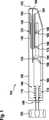
Die Stanzvorrichtung
Optional weist die Stanzvorrichtung
Die Implantateinrichtung
Die Implantiereinrichtung
Die Verschlusseinrichtung
Die Betätigungseinrichtung
Gemäß diesem Ausführungsbeispiel weist die Implantiereinrichtung
Gemäß diesem Ausführungsbeispiel ist die Außenhülse
Die Verschlusseinrichtung
Zum Koppeln der Verschlusseinrichtung
Die Öffnungseinrichtung
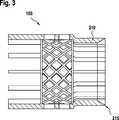
Im Folgenden werden anhand von
Mit reifender Technik sollen vermehrt Maschinen in den Körper von Menschen implantiert werden, dadurch entsteht die Notwendigkeit eines Geräts, das auf minimal invasive Weise ein Loch in ein Blutgefäß, zuvor als Blutgefäß bezeichnet, stanzt und ein Drahtgeflecht wie die Implantateinrichtung
Die vorgestellte Stanzvorrichtung
Auf das Abklemmen der Aorta kann hier vorteilhafterweise verzichtet werden, was erhebliche Vorteile für den Patienten hat, da das Abklemmen von Blutgefäßen z. B. zur Bildung von Thromben führen kann. Wenn diese Thromben sich lösen und beispielsweise an eine Engstelle im Gehirn wandern, kann das zu einem Schlaganfall führen.On the disconnection of the aorta can be advantageously dispensed with here, which has significant benefits for the patient, since the clamping of blood vessels z. B. can lead to the formation of thrombi. If these thrombi separate and, for example, migrate to a constriction in the brain, this can lead to a stroke.
Auch muss der Patient beim Stanzen des Blutgefäßes und Implantieren der Implantateinrichtung
Zusätzlich ist beim Einsatz der vorgestellten Stanzvorrichtung
Wie bereits erläutert wird es durch die vorgestellte Stanzvorrichtung
Die Stanzvorrichtung
Hierbei ist die Stanzvorrichtung
Dargestellt ist eine seitliche Ansicht der Stanzvorrichtung
Die erste Bewegung, die gemäß diesem Ausführungsbeispiel durch Drehen des Drehknopfes
Das Gehäuse
Diese Torsionsfeder dreht die Lineareinheit
Lediglich beispielhaft weist der Sicherungsknopf eine Länge von 25 mm und eine Breite von 10 mm auf, ein Sicherungsstiftdurchmesser beträgt 3 mm, sämtliche weiteren Stifte/Nocken
Beispielhaft ist die Feder
Als mögliche Herstellungsverfahren der Kunststoffteile sind hier beispielhaft ein Spritzgussverfahren oder ein 3D-Druck, beispielsweise ein FDM-Verfahren, genannt.As a possible manufacturing process of the plastic parts, an injection molding process or a 3D printing, for example an FDM process, are mentioned here by way of example.
In der Implantiereinrichtung ist die Implantateinrichtung
Damit das Stanzen möglich ist, ist das Drahtgeflecht im Bereich der Schneidkante
Der Klemmabschnitt
In einem Schritt
Umfasst ein Ausführungsbeispiel eine „und/oder“ -Verknüpfung zwischen einem ersten Merkmal und einem zweiten Merkmal, so ist dies so zu lesen, dass das Ausführungsbeispiel gemäß einer Ausführungsform sowohl das erste Merkmal als auch das zweite Merkmal und gemäß einer weiteren Ausführungsform entweder nur das erste Merkmal oder nur das zweite Merkmal aufweist.If an exemplary embodiment comprises a "and / or" link between a first feature and a second feature, then this is to be read so that the embodiment according to one embodiment, both the first feature and the second feature and according to another embodiment either only first feature or only the second feature.
Claims (14)
Translated fromGermanPriority Applications (3)
| Application Number | Priority Date | Filing Date | Title |
|---|---|---|---|
| DE102016209871.3ADE102016209871A1 (en) | 2016-06-06 | 2016-06-06 | Punching device and method for punching a lumen and implanting an implant device |
| US15/613,409US11000282B2 (en) | 2016-06-06 | 2017-06-05 | Punching device and method for punching a lumen and implanting an implant device |
| US17/222,842US12150647B2 (en) | 2016-06-06 | 2021-04-05 | Method for punching a lumen and implanting an implant device |
Applications Claiming Priority (1)
| Application Number | Priority Date | Filing Date | Title |
|---|---|---|---|
| DE102016209871.3ADE102016209871A1 (en) | 2016-06-06 | 2016-06-06 | Punching device and method for punching a lumen and implanting an implant device |
Publications (1)
| Publication Number | Publication Date |
|---|---|
| DE102016209871A1true DE102016209871A1 (en) | 2017-12-07 |
Family
ID=60328064
Family Applications (1)
| Application Number | Title | Priority Date | Filing Date |
|---|---|---|---|
| DE102016209871.3APendingDE102016209871A1 (en) | 2016-06-06 | 2016-06-06 | Punching device and method for punching a lumen and implanting an implant device |
Country Status (2)
| Country | Link |
|---|---|
| US (2) | US11000282B2 (en) |
| DE (1) | DE102016209871A1 (en) |
Families Citing this family (10)
| Publication number | Priority date | Publication date | Assignee | Title |
|---|---|---|---|---|
| DE102016209871A1 (en) | 2016-06-06 | 2017-12-07 | Robert Bosch Gmbh | Punching device and method for punching a lumen and implanting an implant device |
| DE102018201030B4 (en) | 2018-01-24 | 2025-10-16 | Kardion Gmbh | Magnetic dome element with magnetic bearing function |
| DE102018206724A1 (en) | 2018-05-02 | 2019-11-07 | Kardion Gmbh | Energy transmission system and method for wireless energy transmission |
| DE102018206725A1 (en) | 2018-05-02 | 2019-11-07 | Kardion Gmbh | Receiving unit, transmitting unit, energy transmission system and method for wireless energy transmission |
| DE102018206754A1 (en) | 2018-05-02 | 2019-11-07 | Kardion Gmbh | Method and device for determining the temperature at a surface and use of the method |
| DE102018206750A1 (en) | 2018-05-02 | 2019-11-07 | Kardion Gmbh | Device for inductive energy transfer into a human body and its use |
| DE102018206731A1 (en) | 2018-05-02 | 2019-11-07 | Kardion Gmbh | Device for inductive energy transmission in a human body and use of the device |
| DE102018208555A1 (en) | 2018-05-30 | 2019-12-05 | Kardion Gmbh | Apparatus for anchoring a cardiac assist system in a blood vessel, method of operation, and method of making a device and cardiac assist system |
| US11699551B2 (en) | 2020-11-05 | 2023-07-11 | Kardion Gmbh | Device for inductive energy transmission in a human body and use of the device |
| US11806222B2 (en)* | 2021-08-06 | 2023-11-07 | John Baeke | Apparatus for cutting a material and a method for cutting a negative pressure wound therapy dressing |
Citations (3)
| Publication number | Priority date | Publication date | Assignee | Title |
|---|---|---|---|---|
| US20030040765A1 (en)* | 2001-08-23 | 2003-02-27 | Breznock Eugene Michael | Method and apparatus for trephinating body vessels and hollow organ walls |
| US20110137394A1 (en)* | 2009-05-29 | 2011-06-09 | Xlumena, Inc. | Methods and systems for penetrating adjacent tissue layers |
| US20160067395A1 (en)* | 2013-03-15 | 2016-03-10 | Apk Advanced Medical Technologies, Inc. | Devices, Systems, and Methods for Implanting and Using a Connector in a Tissue Wall |
Family Cites Families (308)
| Publication number | Priority date | Publication date | Assignee | Title |
|---|---|---|---|---|
| US2254698A (en) | 1940-10-04 | 1941-09-02 | Gen Electric | Magnetic system |
| NL128458C (en) | 1961-08-14 | 1900-01-01 | ||
| US3085407A (en) | 1962-03-20 | 1963-04-16 | Sprague Engineering Corp | Coupling means |
| US3645268A (en)* | 1969-12-10 | 1972-02-29 | Dagoberto Capote | Disposable, presterilized, self-locating and piercing evacuator with ejector tube |
| US3614181A (en) | 1970-07-02 | 1971-10-19 | Us Air Force | Magnetic bearing for combined radial and thrust loads |
| DE2108590A1 (en) | 1971-02-23 | 1972-09-07 | Siemens Ag | Arrangement for mounting a high-speed, in particular an electric motor driven shaft |
| US3790878A (en) | 1971-12-22 | 1974-02-05 | Keithley Instruments | Switching regulator having improved control circuiting |
| US4441210A (en) | 1981-09-18 | 1984-04-03 | Hochmair Erwin S | Transcutaneous signal transmission system and methods |
| US4888009A (en) | 1985-04-05 | 1989-12-19 | Abiomed, Inc. | Prosthetic heart valve |
| US4888011A (en) | 1988-07-07 | 1989-12-19 | Abiomed, Inc. | Artificial heart |
| US4896754A (en) | 1988-08-25 | 1990-01-30 | Lord Corporation | Electrorheological fluid force transmission and conversion device |
| US5000177A (en) | 1990-01-29 | 1991-03-19 | Cardiac Pacemakers, Inc. | Bipolar lead adapter with resilient housing and rigid retainers for plug seals |
| US5195877A (en) | 1990-10-05 | 1993-03-23 | Kletschka Harold D | Fluid pump with magnetically levitated impeller |
| US5814900A (en) | 1991-07-30 | 1998-09-29 | Ulrich Schwan | Device for combined transmission of energy and electric signals |
| JP2569419B2 (en) | 1993-02-18 | 1997-01-08 | 工業技術院長 | Artificial heart pump |
| US5289821A (en) | 1993-06-30 | 1994-03-01 | Swartz William M | Method of ultrasonic Doppler monitoring of blood flow in a blood vessel |
| US5511958A (en) | 1994-02-10 | 1996-04-30 | Baxter International, Inc. | Blood pump system |
| GB9404321D0 (en) | 1994-03-04 | 1994-04-20 | Thoratec Lab Corp | Driver and method for driving pneumatic ventricular assist devices |
| US5613935A (en) | 1994-12-16 | 1997-03-25 | Jarvik; Robert | High reliability cardiac assist system |
| JP3064853B2 (en) | 1995-02-03 | 2000-07-12 | 株式会社村田製作所 | choke coil |
| US5713954A (en) | 1995-06-13 | 1998-02-03 | Abiomed R&D, Inc. | Extra cardiac ventricular assist device |
| US5800528A (en) | 1995-06-13 | 1998-09-01 | Abiomed R & D, Inc. | Passive girdle for heart ventricle for therapeutic aid to patients having ventricular dilatation |
| US6254359B1 (en) | 1996-05-10 | 2001-07-03 | The United States Of America As Represented By The Administrator Of The National Aeronautics And Space Administration | Method for providing a jewel bearing for supporting a pump rotor shaft |
| US5690674A (en) | 1996-07-02 | 1997-11-25 | Cordis Corporation | Wound closure with plug |
| US5888242A (en) | 1996-11-01 | 1999-03-30 | Nimbus, Inc. | Speed control system for implanted blood pumps |
| DE69724781T2 (en) | 1997-01-03 | 2004-07-01 | Biosense, Inc., Miami | STENT FOR MEASURING PRESSURE |
| US5843141A (en) | 1997-04-25 | 1998-12-01 | Medronic, Inc. | Medical lead connector system |
| JP3985051B2 (en) | 1997-07-28 | 2007-10-03 | 独立行政法人 日本原子力研究開発機構 | Double wrap dry scroll vacuum pump |
| US6398734B1 (en) | 1997-10-14 | 2002-06-04 | Vascusense, Inc. | Ultrasonic sensors for monitoring the condition of flow through a cardiac valve |
| JP3247328B2 (en) | 1997-12-09 | 2002-01-15 | 浩 坂本 | Non-contact power transmission device |
| EP0930086A1 (en) | 1998-01-15 | 1999-07-21 | Dew Engineering and Development Limited | Transcutaneous energy transfer device |
| US6979338B1 (en)* | 1998-05-29 | 2005-12-27 | By-Pass Inc. | Low profile anastomosis connector |
| US6324431B1 (en) | 1998-07-06 | 2001-11-27 | Abiomed, Inc. | Transcutaneous energy transfer device with magnetic field protected components in secondary coil |
| US6389318B1 (en) | 1998-07-06 | 2002-05-14 | Abiomed, Inc. | Magnetic shield for primary coil of transcutaneous energy transfer device |
| US8489200B2 (en) | 1998-07-06 | 2013-07-16 | Abiomed, Inc. | Transcutaneous energy transfer module with integrated conversion circuitry |
| US6324430B1 (en) | 1998-07-06 | 2001-11-27 | Abiomed, Inc. | Magnetic shield for primary coil of transcutaneous energy transfer device |
| US6149683A (en) | 1998-10-05 | 2000-11-21 | Kriton Medical, Inc. | Power system for an implantable heart pump |
| US6058958A (en) | 1998-11-05 | 2000-05-09 | Micromed Technology, Inc. | Pulsatile flow system and method |
| US6264601B1 (en) | 1999-04-02 | 2001-07-24 | World Heart Corporation | Implantable ventricular assist device |
| US6212430B1 (en) | 1999-05-03 | 2001-04-03 | Abiomed, Inc. | Electromagnetic field source with detection of position of secondary coil in relation to multiple primary coils |
| US6516227B1 (en) | 1999-07-27 | 2003-02-04 | Advanced Bionics Corporation | Rechargeable spinal cord stimulator system |
| US6553263B1 (en) | 1999-07-30 | 2003-04-22 | Advanced Bionics Corporation | Implantable pulse generators using rechargeable zero-volt technology lithium-ion batteries |
| US6445956B1 (en) | 1999-10-18 | 2002-09-03 | Abiomed, Inc. | Implantable medical device |
| US6442434B1 (en) | 1999-10-19 | 2002-08-27 | Abiomed, Inc. | Methods and apparatus for providing a sufficiently stable power to a load in an energy transfer system |
| US6547806B1 (en) | 2000-02-04 | 2003-04-15 | Ni Ding | Vascular sealing device and method of use |
| EP1123687A3 (en) | 2000-02-10 | 2004-02-04 | Aloka Co., Ltd. | Ultrasonic diagnostic apparatus |
| US6361292B1 (en) | 2000-04-12 | 2002-03-26 | Sheldon S. L. Chang | Linear flow blood pump |
| US6561975B1 (en) | 2000-04-19 | 2003-05-13 | Medtronic, Inc. | Method and apparatus for communicating with medical device systems |
| US6530876B1 (en) | 2000-04-25 | 2003-03-11 | Paul A. Spence | Supplemental heart pump methods and systems for supplementing blood through the heart |
| US6540658B1 (en) | 2000-05-30 | 2003-04-01 | Abiomed, Inc. | Left-right flow control algorithm in a two chamber cardiac prosthesis |
| US6527698B1 (en) | 2000-05-30 | 2003-03-04 | Abiomed, Inc. | Active left-right flow control in a two chamber cardiac prosthesis |
| US6471713B1 (en)* | 2000-11-13 | 2002-10-29 | Cardica, Inc. | System for deploying an anastomosis device and method of performing anastomosis |
| US6537921B2 (en) | 2001-05-23 | 2003-03-25 | Vram Technologies, Llc | Vertical metal oxide silicon field effect semiconductor diodes |
| US6666826B2 (en) | 2002-01-04 | 2003-12-23 | Cardiac Pacemakers, Inc. | Method and apparatus for measuring left ventricular pressure |
| US20060004423A1 (en) | 2002-05-09 | 2006-01-05 | Boveja Birinder R | Methods and systems to provide therapy or alleviate symptoms of chronic headache, transformed migraine, and occipital neuralgia by providing rectangular and/or complex electrical pulses to occipital nerves |
| US7338521B2 (en) | 2002-06-13 | 2008-03-04 | World Heart, Inc. | Low profile inlet for an implantable blood pump |
| DE10302550B3 (en) | 2003-01-22 | 2004-08-12 | Forschungszentrum Karlsruhe Gmbh | Belt reel as a transmit / receive antenna in a transponder device |
| US6887207B2 (en) | 2003-02-26 | 2005-05-03 | Medtronic, Inc. | Methods and apparatus for estimation of ventricular afterload based on ventricular pressure measurements |
| TWI257543B (en) | 2003-07-02 | 2006-07-01 | Delta Electronics Inc | Equalizing temperature device |
| DE10335648A1 (en)* | 2003-07-30 | 2005-03-03 | Eberhard-Karls-Universität Tübingen | Closing plug for an opening in a wall of a vessel or hollow organ |
| US7245117B1 (en) | 2004-11-01 | 2007-07-17 | Cardiomems, Inc. | Communicating with implanted wireless sensor |
| US7070398B2 (en) | 2003-09-25 | 2006-07-04 | Medforte Research Foundation | Axial-flow blood pump with magnetically suspended, radially and axially stabilized impeller |
| DE10353943B4 (en) | 2003-11-18 | 2013-01-03 | Deutsches Zentrum für Luft- und Raumfahrt e.V. | Arrangement for the wireless transmission of energy to an implanted device |
| US7520850B2 (en) | 2003-11-19 | 2009-04-21 | Transoma Medical, Inc. | Feedback control and ventricular assist devices |
| US7160243B2 (en) | 2004-03-25 | 2007-01-09 | Terumo Corporation | Method and system for controlling blood pump flow |
| US7513864B2 (en) | 2004-07-09 | 2009-04-07 | Kantrowitz Allen B | Synchronization system between aortic valve and cardiac assist device |
| EP2151257B1 (en) | 2004-08-13 | 2013-04-17 | Delgado, Reynolds M., III | Apparatus for long-term assisting a left ventricle to pump blood |
| US8077437B2 (en) | 2004-11-08 | 2011-12-13 | Enecsys Limited | Integrated circuits and power supplies |
| US20080015481A1 (en) | 2005-05-04 | 2008-01-17 | Bergin Patrick J | Hemostatic bandage and method of use |
| KR100792311B1 (en) | 2005-07-30 | 2008-01-07 | 엘에스전선 주식회사 | Charging power supply, charging device, battery unit, contactless charging system and contactless charging method |
| US9026211B2 (en) | 2005-08-30 | 2015-05-05 | Boston Scientific Neuromodulation Corporation | Battery charger circuit for battery powered implantable neurostimulation systems |
| US9283314B2 (en) | 2005-09-21 | 2016-03-15 | Abiomed, Inc. | Cannula systems |
| US7650192B2 (en) | 2005-12-02 | 2010-01-19 | Medtronic, Inc. | Passive charge of implantable medical device utilizing external power source and method |
| US11201500B2 (en) | 2006-01-31 | 2021-12-14 | Mojo Mobility, Inc. | Efficiencies and flexibilities in inductive (wireless) charging |
| AT503628B1 (en) | 2006-04-25 | 2008-06-15 | Vc Trust Holding Gmbh | METHOD FOR MONITORING THE MAXIMUM DISTANCE OF TWO OBJECTS |
| US7468039B2 (en) | 2006-06-02 | 2008-12-23 | Cook Vascular Incorporated | Adjustable tension cuff assembly |
| US7909770B2 (en) | 2006-07-05 | 2011-03-22 | Cardiomems, Inc. | Method for using a wireless pressure sensor to monitor pressure inside the human heart |
| US8004235B2 (en) | 2006-09-29 | 2011-08-23 | Access Business Group International Llc | System and method for inductively charging a battery |
| AU2008219653B2 (en) | 2007-02-26 | 2014-01-16 | Heartware, Inc. | Intravascular ventricular assist device |
| US9974894B2 (en) | 2007-04-05 | 2018-05-22 | Reliantheart, Inc. | Blood pump system |
| US7762941B2 (en) | 2007-04-25 | 2010-07-27 | Robert Jarvik | Blood pump bearings with separated contact surfaces |
| US8075472B2 (en) | 2007-05-03 | 2011-12-13 | Leviticus-Cardio Ltd. | Permanent ventricular assist device for treating heart failure |
| JP5201887B2 (en) | 2007-06-20 | 2013-06-05 | テルモ株式会社 | Blood pump system for artificial heart and device monitoring system |
| US20090010462A1 (en) | 2007-07-02 | 2009-01-08 | Front Edge Technology, Inc. | Compact rechargeable thin film battery system for hearing aid |
| US20090024042A1 (en) | 2007-07-03 | 2009-01-22 | Endotronix, Inc. | Method and system for monitoring ventricular function of a heart |
| WO2009023905A1 (en) | 2007-08-17 | 2009-02-26 | Ventrassist Pty Ltd | Transcutaneous energy transfer coil assemblies and systems |
| WO2009029977A1 (en) | 2007-09-03 | 2009-03-12 | Ventrassist Pty Ltd | Transcutaneous energy transfer coil assembly |
| GB0718943D0 (en) | 2007-09-28 | 2007-11-07 | Univ Nottingham | Mechanical support |
| US8923968B2 (en) | 2007-10-30 | 2014-12-30 | Cochlear Limited | Power link for implantable devices |
| US9199020B2 (en) | 2007-11-01 | 2015-12-01 | Abiomed, Inc. | Purge-free miniature rotary pump |
| US7960867B2 (en) | 2007-11-27 | 2011-06-14 | Extremely Ingenious Engineering | Methods and systems for wireless energy and data transmission |
| US7794384B2 (en) | 2007-12-07 | 2010-09-14 | Terumo Heart, Inc. | Dual communication interface for artificial heart system |
| US7942805B2 (en) | 2007-12-27 | 2011-05-17 | Heartware, Inc. | VAD connector plug |
| US8391982B2 (en) | 2008-01-31 | 2013-03-05 | Boston Scientific Neuromodulation Corporation | Lead with lead stiffener for implantable electrical stimulation systems and methods of making and using |
| US8301262B2 (en) | 2008-02-06 | 2012-10-30 | Cardiac Pacemakers, Inc. | Direct inductive/acoustic converter for implantable medical device |
| US8229567B2 (en) | 2008-04-30 | 2012-07-24 | Medtronic, Inc. | Concentric primary coils for inductively charging an implantable medical device, external power source and method |
| US20090312650A1 (en) | 2008-06-12 | 2009-12-17 | Cardiac Pacemakers, Inc. | Implantable pressure sensor with automatic measurement and storage capabilities |
| US9713701B2 (en) | 2008-07-31 | 2017-07-25 | Medtronic, Inc. | Using multiple diagnostic parameters for predicting heart failure events |
| AU2009292201B2 (en) | 2008-09-10 | 2015-04-16 | Heartware, Inc. | TET system for implanted medical device |
| US8901778B2 (en) | 2008-09-27 | 2014-12-02 | Witricity Corporation | Wireless energy transfer with variable size resonators for implanted medical devices |
| WO2010042054A1 (en) | 2008-10-10 | 2010-04-15 | Milux Holding S.A. | Charger for implant |
| EP2349079B1 (en) | 2008-10-10 | 2023-06-07 | Implantica Patent Ltd. | Charger for implant |
| WO2010080717A1 (en) | 2009-01-12 | 2010-07-15 | The Board Of Trustees Of The Leland Stanford Junior University | Drainage device and method |
| US7993259B2 (en) | 2009-01-23 | 2011-08-09 | Wei-Chang Kang | Percutaneous intra-aortic ventricular assist device |
| US20100280568A1 (en) | 2009-04-30 | 2010-11-04 | Cherik Bulkes | Implantable High Efficiency Energy Transfer Module With Near-Field Inductive Coupling |
| US8231519B2 (en) | 2009-05-20 | 2012-07-31 | Thoratec Corporation | Multi-lumen cannula |
| US9782527B2 (en) | 2009-05-27 | 2017-10-10 | Tc1 Llc | Monitoring of redundant conductors |
| US20100331918A1 (en) | 2009-06-30 | 2010-12-30 | Boston Scientific Neuromodulation Corporation | Moldable charger with curable material for charging an implantable pulse generator |
| RU2548367C2 (en) | 2009-07-13 | 2015-04-20 | Конинклейке Филипс Электроникс Н.В. | Energy inductive transmission |
| US8628460B2 (en) | 2009-09-21 | 2014-01-14 | Heartware, Inc. | Hard-wired implanted controller system |
| US8579789B1 (en) | 2009-09-23 | 2013-11-12 | Leviticus Cardio Ltd. | Endovascular ventricular assist device, using the mathematical objective and principle of superposition |
| DE102009047844A1 (en) | 2009-09-30 | 2011-03-31 | Abiomed Europe Gmbh | Lockable quick release |
| EP2515996B1 (en) | 2009-12-23 | 2019-09-18 | Setpoint Medical Corporation | Neural stimulation devices and systems for treatment of chronic inflammation |
| US20110224720A1 (en) | 2010-03-11 | 2011-09-15 | Cvdevices, Llc | Devices, systems, and methods for closing a hole in cardiac tissue |
| SE535140C2 (en) | 2010-03-25 | 2012-04-24 | Jan Otto Solem | An implantable device, kit and system for improving cardiac function, including means for generating longitudinal movement of the mitral valve |
| US9833314B2 (en) | 2010-04-16 | 2017-12-05 | Abiomed, Inc. | Percutaneous valve deployment |
| WO2012012552A1 (en) | 2010-07-22 | 2012-01-26 | Thoratec Corporation | Controlling implanted blood pumps |
| WO2012019126A1 (en) | 2010-08-06 | 2012-02-09 | Heartware, Inc. | Conduit device for use with a ventricular assist device |
| EP2422735A1 (en) | 2010-08-27 | 2012-02-29 | ECP Entwicklungsgesellschaft mbH | Implantable blood transportation device, manipulation device and coupling device |
| US8830637B2 (en) | 2010-08-31 | 2014-09-09 | Texas Instruments Incorporated | Methods and apparatus to clamp overvoltages for alternating current systems |
| US8551163B2 (en) | 2010-10-07 | 2013-10-08 | Everheart Systems Inc. | Cardiac support systems and methods for chronic use |
| AU2011329457B2 (en) | 2010-11-19 | 2015-01-22 | Cardiac Pacemakers, Inc. | Peel-away IS-4/DF-4 lead implant tool with electrical contacts |
| US9801702B2 (en) | 2010-12-16 | 2017-10-31 | Boston Scientific Scimed, Inc. | Artificial sphincter system and method |
| US20120158074A1 (en) | 2010-12-20 | 2012-06-21 | Medicine Hall Of America, Inc. | Fitted garment comprising heart monitoring with defibrillation capability |
| DK2654878T3 (en) | 2010-12-20 | 2019-07-22 | Abiomed Inc | TRANSCUTANT ENERGY TRANSFER SYSTEM WITH A MULTIPLE OF SECONDARY COILS |
| WO2012087819A2 (en) | 2010-12-20 | 2012-06-28 | Abiomed, Inc. | Transcutaneous energy transfer system with vibration inducing warning circuitry |
| JP2014502528A (en) | 2010-12-20 | 2014-02-03 | アビオメド インコーポレイティド | Method and apparatus for accurately tracking charge available in a transdermal energy transmission system |
| KR101243587B1 (en) | 2011-02-17 | 2013-03-20 | 주식회사 팬택 | Non-contract charging device, non-contact charghing system and non-contact charging method |
| US20120277155A1 (en) | 2011-02-25 | 2012-11-01 | Medtronic, Inc. | Therapy for kidney disease and/or heart failure |
| EP2697890B1 (en) | 2011-04-14 | 2019-02-20 | Abiomed, Inc. | Transcutaneous energy transfer coil with integrated radio frequency antenna |
| GB201106982D0 (en) | 2011-04-27 | 2011-06-08 | Univ Ulster | Defobrillator apparatus and method |
| WO2012158543A1 (en) | 2011-05-13 | 2012-11-22 | Heartware, Inc. | Intravascular blood pump and method of implantation |
| EP2524709A1 (en) | 2011-05-16 | 2012-11-21 | Berlin Heart GmbH | Connection system for reversible fixing of a hollow cylindrical component to a recess |
| KR101185112B1 (en) | 2011-05-27 | 2012-09-21 | 주식회사 엠아이텍 | Medical instrument and power controlling method thereof |
| JP5849343B2 (en) | 2011-06-29 | 2016-01-27 | 株式会社プロスパイン | Magnetic coupling and stirring device |
| WO2013023009A1 (en) | 2011-08-11 | 2013-02-14 | Spence Paul A | Devices, methods and systems for counterpulsation and blood flow conduit connection |
| CA2784988A1 (en) | 2011-08-18 | 2013-02-18 | Agron Lumiani | Mrt local coil apparatus for diagnostics, intervention and therapy |
| US9508487B2 (en) | 2011-10-21 | 2016-11-29 | Qualcomm Incorporated | Systems and methods for limiting voltage in wireless power receivers |
| US20130116575A1 (en) | 2011-11-04 | 2013-05-09 | Marlin Mickle | Implantable doppler blood flow monitor and doppler probe |
| US9079043B2 (en) | 2011-11-21 | 2015-07-14 | Thoratec Corporation | Transcutaneous power transmission utilizing non-planar resonators |
| DK2782618T3 (en) | 2011-11-23 | 2020-09-07 | Abiomed Inc | TRANSPLANT FOR USE WITH MODPULSATION DEVICE |
| JP6139550B2 (en) | 2011-11-28 | 2017-05-31 | ミ‐ヴァド インコーポレイテッド | Auxiliary circulation apparatus and method |
| US9002468B2 (en) | 2011-12-16 | 2015-04-07 | Abiomed, Inc. | Automatic power regulation for transcutaneous energy transfer charging system |
| JP6295204B2 (en) | 2011-12-23 | 2018-03-14 | アビオメド インコーポレイテッド | Heart valve prosthesis with an open stent |
| KR102042498B1 (en) | 2012-01-11 | 2019-11-11 | 삼성전자주식회사 | Overvoltage protecting device for resonance wireless power receiving apparatus and controlling method thereof |
| US11005285B2 (en) | 2012-03-21 | 2021-05-11 | Mojo Mobility, Inc. | Wireless power transfer |
| DE102012200912B4 (en) | 2012-01-23 | 2015-05-07 | Dualis Medtech Gmbh | Carrying device for carrying a transmitting coil |
| US11389638B2 (en) | 2012-02-07 | 2022-07-19 | Hridaya, Inc. | Hemodynamic assist device |
| US9981076B2 (en) | 2012-03-02 | 2018-05-29 | Tc1 Llc | Ventricular cuff |
| DE112012005944T5 (en) | 2012-04-27 | 2014-12-18 | Mitsubishi Electric Corporation | DC / DC converter, on-board unit and charger |
| WO2013164831A1 (en) | 2012-05-03 | 2013-11-07 | Powermat Technologies Ltd. | System and method for triggering power transfer across an inductive power coupling and non resonant transmission |
| US9569985B2 (en) | 2012-05-07 | 2017-02-14 | St. Jude Medical, Cardiology Division, Inc. | Transcatheter heart valve delivery deployment simulator |
| US9446179B2 (en) | 2012-05-14 | 2016-09-20 | Thoratec Corporation | Distal bearing support |
| US8827890B2 (en) | 2012-05-17 | 2014-09-09 | Thoratec Corporation | Touch screen interface and infrared communication system integrated into a battery |
| AU2013204571C1 (en) | 2012-05-22 | 2015-12-17 | Sunshine Heart Company Pty Limited | Methods, systems, and devices relating to a removable percutaneous interface line |
| CA2875340C (en) | 2012-06-11 | 2017-08-15 | Heartware, Inc. | Self-adhesive tet coil holder with alignment feature |
| US9907699B2 (en)* | 2012-07-05 | 2018-03-06 | Domestic Legacy Limited Partnership | One step tympanostomy tube and method of inserting same |
| EP4257174A3 (en) | 2012-07-27 | 2023-12-27 | Tc1 Llc | Thermal management for implantable wireless power transfer systems |
| US8897891B2 (en) | 2012-08-03 | 2014-11-25 | Boston Scientific Neuromodulation Corporation | Leads with electrode carrier for segmented electrodes and methods of making and using |
| CA3113910C (en) | 2012-08-10 | 2023-09-19 | Abiomed, Inc. | Graft anchor devices, systems, and methods |
| US9130369B2 (en) | 2012-08-29 | 2015-09-08 | Qualcomm Incorporated | Wireless power overvoltage protection circuit with reduced power dissipation |
| KR20150052215A (en) | 2012-09-05 | 2015-05-13 | 하트웨어, 인코포레이티드 | Vad integrated flow sensor |
| JP5638043B2 (en) | 2012-09-07 | 2014-12-10 | ファナック株式会社 | Motor drive device having alarm level setting unit |
| US9438062B2 (en) | 2012-10-12 | 2016-09-06 | Samsung Electronics Co., Ltd | Wireless electric power receiver for wirelessly regulating electric power using switch |
| WO2014062547A1 (en) | 2012-10-17 | 2014-04-24 | Cardiac Pacemakers, Inc. | Terminal ring configuration to prevent improper is4 lead connector electrical contact with df4 connector port |
| CN103143072B (en) | 2012-12-21 | 2015-06-17 | 北京工业大学 | Auxiliary circulation blood pump adopted in serially connecting operation modes and installing method of auxiliary circulation blood pump |
| DE102013200152A1 (en) | 2013-01-08 | 2014-07-10 | AdjuCor GmbH | Heart support device with a self-expanding shell |
| CN103942511A (en) | 2013-01-18 | 2014-07-23 | 陆婷 | Design and realization method of simple wireless identification apparatus |
| US9537344B2 (en) | 2013-02-21 | 2017-01-03 | Cyberonics, Inc. | Phase change material as a dynamic heat sink for trancutaneous energy transmission systems |
| US9539094B2 (en) | 2013-03-13 | 2017-01-10 | St. Jude Medical, Cardiology Division, Inc. | Simulated environment for transcatheter heart valve repair |
| EP2984731B8 (en) | 2013-03-15 | 2019-06-26 | Tc1 Llc | Malleable tets coil with improved anatomical fit |
| US9848899B2 (en) | 2013-03-15 | 2017-12-26 | St. Jude Medical, Atrial Fibrillation Division, Inc. | Pressure sensing of irrigant backpressure for aligning directional medical devices with target tissue |
| EP2782210B1 (en) | 2013-03-21 | 2018-11-28 | Samsung Electronics Co., Ltd. | Wireless power transmitting unit, wireless power receiving unit, and control methods thereof |
| US9427508B2 (en) | 2013-06-04 | 2016-08-30 | Heartware, Inc. | Axial flow pump pressure algorithm |
| JP6110236B2 (en) | 2013-07-02 | 2017-04-05 | ルネサスエレクトロニクス株式会社 | Power receiving device and non-contact power feeding system |
| WO2015013666A1 (en) | 2013-07-26 | 2015-01-29 | Cardiaq Valve Technologies, Inc. | Systems and methods for sealing openings in an anatomical wall |
| AU2014296320B2 (en) | 2013-07-29 | 2018-07-26 | Alfred E. Mann Foundation For Scientific Research | Implant charging field control through radio link |
| CN105765096A (en) | 2013-10-02 | 2016-07-13 | 纳米钢公司 | Mechanisms of recrystallization, refinement and strengthening for the preparation of advanced high-strength metal alloys |
| EP2859911A1 (en) | 2013-10-11 | 2015-04-15 | qSTAR Medical SAS | Vascular access port devices with incorporated sensors |
| US10695476B2 (en) | 2013-11-11 | 2020-06-30 | Tc1 Llc | Resonant power transfer systems with communications |
| EP3077018B1 (en) | 2013-12-04 | 2021-10-27 | Heartware, Inc. | Molded vad |
| KR20160101958A (en) | 2013-12-26 | 2016-08-26 | 미쓰비시 덴끼 엔지니어링 가부시키가이샤 | Automatic matching circuit for high-frequency power supply |
| US20150196076A1 (en) | 2014-01-15 | 2015-07-16 | Janice Althea Gregg Billingslea | Medical Equipment Garment T-Shirt |
| EP3110468B1 (en) | 2014-02-25 | 2021-11-03 | Kushwaha, Sudhir | Ventricular assist device and method |
| CN104901429A (en) | 2014-03-05 | 2015-09-09 | 库珀工业控股(爱尔兰)公司 | Magnetic coupling resonant wireless energy transmission receiving circuit |
| WO2015139031A1 (en) | 2014-03-14 | 2015-09-17 | Cardiac Assist, Inc. | Image-guided transseptal puncture device |
| CN106463993A (en) | 2014-04-02 | 2017-02-22 | 鲍尔拜普罗克西有限公司 | Low power inductive power receiver |
| WO2015160993A1 (en) | 2014-04-15 | 2015-10-22 | Thoratec Corporation | Methods and systems for providing battery feedback to patient |
| US10376624B2 (en) | 2014-04-15 | 2019-08-13 | Heartware, Inc. | Transcutaneous energy transfer systems |
| WO2015160943A1 (en) | 2014-04-15 | 2015-10-22 | Thoratec Corporation | Sensors for catheter pumps |
| EP3131601B1 (en) | 2014-04-15 | 2018-07-25 | Heartware, Inc. | Improvements in transcutaneous energy transfer systems |
| US9800172B1 (en) | 2014-05-07 | 2017-10-24 | Energous Corporation | Integrated rectifier and boost converter for boosting voltage received from wireless power transmission waves |
| US9831685B2 (en) | 2014-05-16 | 2017-11-28 | Samsung Electro-Mechanics Co., Ltd. | Wireless power transmitter |
| US11103715B2 (en) | 2014-06-27 | 2021-08-31 | Cochlear Limited | Devices and methods for charging medical devices |
| DE102015112098A1 (en) | 2014-07-25 | 2016-01-28 | Minnetronix, Inc. | Coil parameters and control |
| JP6474896B2 (en) | 2014-08-01 | 2019-02-27 | ヴァドヴェイションズ,インコーポレイテッド | Coring dilator that defines an opening in the tissue wall |
| JP6228713B1 (en) | 2014-09-03 | 2017-11-08 | ティーシー1 エルエルシー | Triple helical driveline cable and method of assembly and use |
| US20170303375A1 (en) | 2014-09-12 | 2017-10-19 | Tru-Test Limited | An electric fence energiser system and methods of operation and components thereof |
| US9795366B2 (en) | 2014-09-18 | 2017-10-24 | Edwards Lifesciences Corporation | Bio-absorbable wound closure device and method |
| JP6193831B2 (en) | 2014-09-19 | 2017-09-06 | ファナック株式会社 | Motor control device having function for determining start of protective operation of machine |
| EP3826104B1 (en) | 2014-09-22 | 2023-05-03 | Tc1 Llc | Antenna designs for communication between a wirelessly powered implant to an external device outside the body |
| EP3200846B1 (en) | 2014-10-01 | 2020-01-15 | Heartware, Inc. | Backup controller system with updating |
| CN104274873A (en) | 2014-10-13 | 2015-01-14 | 长治市久安人工心脏科技开发有限公司 | Miniature apex cordis axial-flow blood pump and implanting method thereof |
| US9561362B2 (en) | 2014-11-10 | 2017-02-07 | Boston Scientific Neuromodulation Corporation | Systems and methods for making and using improved contact arrays for electrical stimulation systems |
| WO2016100334A1 (en) | 2014-12-19 | 2016-06-23 | Heartware, Inc. | Guidewire system and method of pump installation using same |
| US10350341B2 (en) | 2015-03-20 | 2019-07-16 | Drexel University | Impellers, blood pumps, and methods of treating a subject |
| WO2016164361A1 (en) | 2015-04-10 | 2016-10-13 | Boston Scientific Neuromodulation Corporation | Systems and methods for making and using improved contact arrays for electrical stimulation systems |
| US20160303301A1 (en) | 2015-04-14 | 2016-10-20 | Minnetronix, Inc. | Implantable power pack |
| CN104888293B (en) | 2015-04-28 | 2017-03-22 | 武汉理工大学 | Implantable axial-flow type blood pump temperature detection system and method based on fiber bragg gratings |
| US10050476B2 (en) | 2015-05-12 | 2018-08-14 | Newpace Ltd. | Rechargeable implantable cardioverter defibrillator |
| JP6554317B2 (en) | 2015-05-18 | 2019-07-31 | ローム株式会社 | Synchronous rectifier circuit, control circuit therefor, wireless power receiver and electronic device |
| GB201513596D0 (en) | 2015-07-31 | 2015-09-16 | Univ Ulster The | Transcutaneous energy transfer systems and methods |
| US10492938B2 (en) | 2015-08-11 | 2019-12-03 | Terumo Corporation | System and method for implant delivery |
| US20170047781A1 (en) | 2015-08-12 | 2017-02-16 | Qualcomm Incorporated | Method and apparatus for in-band signaling using parasitic resistances |
| EP3340925B1 (en) | 2015-08-28 | 2020-09-23 | Tc1 Llc | Blood pump controllers and methods of use for improved energy efficiency |
| EP3153190A1 (en) | 2015-10-09 | 2017-04-12 | ECP Entwicklungsgesellschaft mbH | Pump, in particular blood pump |
| US20180271445A1 (en) | 2015-10-14 | 2018-09-27 | St. Jude Medical, Cardiology Division, Inc. | Vascular sensor implantation devices and methods |
| US10130743B2 (en) | 2015-11-17 | 2018-11-20 | Dale J. Yeatts | Wireless diagnostic system for indirect flow measurement in artificial heart pumps |
| EP3377133B1 (en) | 2015-11-20 | 2021-07-14 | Tc1 Llc | System architecture that allows patient replacement of vad controller/interface module without disconnection of old module |
| EP3377136B1 (en) | 2015-11-20 | 2020-05-06 | Tc1 Llc | Energy management of blood pump controllers |
| EP3377135B1 (en) | 2015-11-20 | 2020-05-06 | Tc1 Llc | Blood pump controllers having daisy-chained batteries |
| PL3693057T3 (en) | 2015-11-23 | 2023-02-20 | Zoll Medical Corporation | Garments for wearable medical devices |
| DE102015223541A1 (en) | 2015-11-27 | 2017-06-01 | Albert-Ludwigs-Universität Freiburg | Implantable fluid pump system |
| CN108430532B (en) | 2015-12-28 | 2020-12-11 | 心脏器械股份有限公司 | Pump Motor Control with Adaptive Start |
| CN108697424A (en) | 2016-01-08 | 2018-10-23 | 纽哈特股份公司 | Connector for coupling anatomical wall and method |
| US10342983B2 (en) | 2016-01-14 | 2019-07-09 | Boston Scientific Neuromodulation Corporation | Systems and methods for making and using connector contact arrays for electrical stimulation systems |
| EP3202433A1 (en) | 2016-02-04 | 2017-08-09 | Berlin Heart GmbH | Outlet graft and system comprising a blood pump and an outlet graft |
| EP3423126B1 (en) | 2016-03-02 | 2021-02-24 | HeartWare, Inc. | Skin button with flat cable |
| EP3220505B8 (en) | 2016-03-16 | 2018-10-31 | Blue Inductive GmbH | Inductive power transfer control |
| US20170271919A1 (en) | 2016-03-21 | 2017-09-21 | Qualcomm Incorporated | Wireless implant powering via subcutaneous power relay |
| EP3432945B1 (en) | 2016-03-21 | 2025-07-16 | Ramtin Agah | Methods and systems for deployment, charging and retrieval of intracardiac pumps |
| US10563332B2 (en) | 2016-03-28 | 2020-02-18 | Hsuan-Tai CHEN | Closed-loop control device of a mechanical sewing machine and method for controlling the same |
| WO2017172738A1 (en) | 2016-03-30 | 2017-10-05 | Heartware, Inc. | Flanged heart tissue blocker |
| EP3226431B1 (en) | 2016-04-01 | 2019-09-04 | Intel IP Corporation | Apparatus and method for aligning a wireless chargeable device with a wireless charger |
| WO2017173217A1 (en) | 2016-04-01 | 2017-10-05 | Heartware, Inc. | Axial flow blood pump with radially offset rotor |
| DE102016209871A1 (en) | 2016-06-06 | 2017-12-07 | Robert Bosch Gmbh | Punching device and method for punching a lumen and implanting an implant device |
| US10483804B2 (en) | 2016-06-07 | 2019-11-19 | Mediatek Inc. | Monotonic wireless power transfer |
| US11471692B2 (en) | 2016-06-15 | 2022-10-18 | Boston Scientific Neuromodulation Corporation | External charger for an implantable medical device for adjusting charging power based on determined position using at least one sense coil |
| US10603501B2 (en) | 2016-06-15 | 2020-03-31 | Boston Scientific Neuromodulation Corporation | External charger for an implantable medical device having at least one sense coil concentric with a charging coil for determining position |
| KR20180007117A (en) | 2016-07-12 | 2018-01-22 | 삼성전자주식회사 | Wireless power transmitter and wireless power receiver and method for operating thereof |
| WO2018017716A1 (en) | 2016-07-21 | 2018-01-25 | Tc1 Llc | Rotary seal for cantilevered rotor pump and methods for axial flow blood pumping |
| US10258724B2 (en) | 2016-08-01 | 2019-04-16 | Heartware, Inc. | VAD with aortic valve opening detection |
| US11224344B2 (en) | 2016-08-19 | 2022-01-18 | James Foody | Method and system for determination of core body temperature |
| US10894116B2 (en) | 2016-08-22 | 2021-01-19 | Tc1 Llc | Heart pump cuff |
| ES2754405T3 (en) | 2016-08-23 | 2020-04-17 | Abiomed Europe Gmbh | Ventricular assist device |
| ES2756525T3 (en) | 2016-09-01 | 2020-04-27 | Abiomed Europe Gmbh | Blood pump with flow cannula |
| JP6612201B2 (en) | 2016-09-16 | 2019-11-27 | 株式会社東芝 | Power supply circuit and power supply device |
| EP4084271A1 (en) | 2016-09-21 | 2022-11-02 | Tc1 Llc | Systems and methods for locating implanted wireless power transmission devices |
| EP3311859B1 (en) | 2016-10-19 | 2019-12-04 | Abiomed Europe GmbH | Ventricular assist device control |
| CN106776441A (en) | 2016-11-25 | 2017-05-31 | 合肥海亚信息科技有限公司 | One kind is based on circuit identifying system system in NFC label cable trough |
| US9839734B1 (en) | 2016-12-02 | 2017-12-12 | Berlin Heart Gmbh | Aortic pump devices and methods |
| US10532196B2 (en) | 2016-12-12 | 2020-01-14 | Boston Scientific Scimed, Inc. | Stent trimming devices and methods |
| US20180193543A1 (en) | 2017-01-09 | 2018-07-12 | Benjamin Sun | Implantable intravascular ventricular assist device |
| US10919401B2 (en) | 2017-01-12 | 2021-02-16 | Ford Global Technologies, Llc | Integrated wireless power transfer system |
| ES2856975T3 (en) | 2017-02-07 | 2021-09-28 | Abiomed Europe Gmbh | Blood pump |
| JP6350699B1 (en) | 2017-03-02 | 2018-07-04 | オムロン株式会社 | Non-contact power feeding device |
| US11065436B2 (en) | 2017-03-29 | 2021-07-20 | Tc1 Llc | Communication methods and architecture for heart treatment systems |
| US10404093B2 (en) | 2017-04-26 | 2019-09-03 | Biosense Webster (Israel) Ltd. | Using location transmission signals for charging a wireless medical tool of an electromagnetic navigation system |
| WO2018213089A1 (en) | 2017-05-16 | 2018-11-22 | Heartware, Inc. | Intra ventricular ambulatory implantable pv loop system |
| EP3646328A4 (en) | 2017-06-29 | 2021-04-21 | Quanticision Diagnostics Inc. | Apparatus and method for absolute quantification of biomarkers for solid tumor diagnosis |
| DE102017213475A1 (en) | 2017-08-03 | 2019-02-07 | Robert Bosch Gmbh | Seal for sealing a hole of a blood vessel |
| DE102017213477A1 (en) | 2017-08-03 | 2019-02-07 | Robert Bosch Gmbh | Seal for sealing a hole of a blood vessel |
| DE102017213469A1 (en) | 2017-08-03 | 2019-02-07 | Robert Bosch Gmbh | Device for connection to a cable of an implant and associated system |
| US11108277B2 (en) | 2017-08-25 | 2021-08-31 | Apple Inc. | Wireless power transfer control based on required and received power error |
| US11110265B2 (en) | 2017-11-03 | 2021-09-07 | Heartware, Inc. | Updating a VAD system without stopping the pump |
| EP3485926A1 (en) | 2017-11-16 | 2019-05-22 | Berlin Heart GmbH | Inlet cannula for a fluid pump |
| DE102017220777A1 (en) | 2017-11-21 | 2019-05-23 | Robert Bosch Gmbh | Cable with seal for an implant |
| US20190175808A1 (en) | 2017-12-12 | 2019-06-13 | Leviticus Cardio Ltd. | Hybrid powering system for an implanted medical device |
| EP3638336B1 (en) | 2018-01-10 | 2022-04-06 | Magenta Medical Ltd. | Ventricular assist device |
| CN110034539B (en) | 2018-01-12 | 2021-06-25 | 泰达电子股份有限公司 | Fault protection method and applicable wireless power transmission device |
| DE102018201030B4 (en) | 2018-01-24 | 2025-10-16 | Kardion Gmbh | Magnetic dome element with magnetic bearing function |
| EP3752237A4 (en) | 2018-02-13 | 2021-11-17 | White Swell Medical Ltd | INTRAVASCULAR CATHETERS |
| EP3755237B1 (en) | 2018-02-20 | 2022-04-27 | Boston Scientific Scimed Inc. | Medical device release system |
| US11529508B2 (en) | 2018-03-02 | 2022-12-20 | Tc1 Llc | Wearable accessory for ventricular assist system |
| EP4461341A3 (en) | 2018-03-15 | 2025-01-15 | Tc1 Llc | Systems for preventing right heart failure |
| US11602627B2 (en) | 2018-03-20 | 2023-03-14 | Second Heart Assist, Inc. | Circulatory assist pump |
| WO2019183126A1 (en) | 2018-03-20 | 2019-09-26 | Tc1 Llc | Mechanical gauge for estimating inductance changes in resonant power transfer systems with flexible coils for use with implanted medical devices |
| US11389641B2 (en) | 2018-03-21 | 2022-07-19 | Tc1 Llc | Modular flying lead cable and methods for use with heart pump controllers |
| DE102018204604A1 (en) | 2018-03-27 | 2019-10-02 | Kardion Gmbh | Plug and plug system for contacting a cable with an implantable device and method for contacting |
| DE102018204610A1 (en) | 2018-03-27 | 2019-10-02 | Kardion Gmbh | Plug for contacting a cable with an implantable device and cable with plug and manufacturing method |
| DE102018206731A1 (en) | 2018-05-02 | 2019-11-07 | Kardion Gmbh | Device for inductive energy transmission in a human body and use of the device |
| DE102018206754A1 (en) | 2018-05-02 | 2019-11-07 | Kardion Gmbh | Method and device for determining the temperature at a surface and use of the method |
| DE102018206725A1 (en) | 2018-05-02 | 2019-11-07 | Kardion Gmbh | Receiving unit, transmitting unit, energy transmission system and method for wireless energy transmission |
| DE102018206727A1 (en) | 2018-05-02 | 2019-11-07 | Kardion Gmbh | Energy transmission system and receiving unit for wireless transcutaneous energy transmission |
| DE102018206750A1 (en) | 2018-05-02 | 2019-11-07 | Kardion Gmbh | Device for inductive energy transfer into a human body and its use |
| DE102018206724A1 (en) | 2018-05-02 | 2019-11-07 | Kardion Gmbh | Energy transmission system and method for wireless energy transmission |
| DE102018206758A1 (en) | 2018-05-02 | 2019-11-07 | Kardion Gmbh | Device for inductive energy transmission in a human body and use of the device |
| DE102018206714A1 (en) | 2018-05-02 | 2019-11-07 | Kardion Gmbh | Receiving unit and energy transmission system for wireless energy transmission |
| DE102018208555A1 (en) | 2018-05-30 | 2019-12-05 | Kardion Gmbh | Apparatus for anchoring a cardiac assist system in a blood vessel, method of operation, and method of making a device and cardiac assist system |
| DE102018208927A1 (en) | 2018-06-06 | 2019-12-12 | Kardion Gmbh | An implantable device for determining a fluid volume flow through a blood vessel |
| US12364855B2 (en) | 2018-06-13 | 2025-07-22 | Yale University | Intracardiac device |
| WO2019244031A1 (en) | 2018-06-18 | 2019-12-26 | Werner Mohl | Stent pump |
| US11241570B2 (en) | 2018-07-17 | 2022-02-08 | Tc1 Llc | Systems and methods for inertial sensing for VAD diagnostics and closed loop control |
| WO2020068480A1 (en) | 2018-09-27 | 2020-04-02 | Heartware, Inc. | Map estimation on vad patients |
| WO2020081321A1 (en) | 2018-10-19 | 2020-04-23 | Tc1 Llc | Implantable blood pump assembly including outflow graft fixation clip |
| WO2020091910A1 (en) | 2018-11-02 | 2020-05-07 | W. L. Gore & Associates, Inc. | Implantable ventricular assist devices and methods |
| DE102018218770A1 (en) | 2018-11-02 | 2020-05-07 | Kardion Gmbh | System and method for controlling a cardiac assist system |
| US11070098B2 (en) | 2019-01-16 | 2021-07-20 | Google Llc | Wireless charger with adaptive alignment assistance |
| AU2020211431B2 (en) | 2019-01-24 | 2024-10-24 | Magenta Medical Ltd | Ventricular assist device |
| CN111668941A (en) | 2019-03-05 | 2020-09-15 | 恩智浦美国有限公司 | Overvoltage protection circuitry for wireless power receivers |
| JP7729779B2 (en) | 2019-03-26 | 2025-08-26 | パズル メディカル デバイシズ インコーポレイテッド | Modular mammalian body implantable fluid flow affecting device and related methods |
| EP4058078B1 (en) | 2019-08-21 | 2025-02-26 | Boston Scientific Scimed Inc. | Circulatory support pump centering anchoring & centering device |
| US11394251B2 (en) | 2019-11-11 | 2022-07-19 | Renesas Electronics America Inc. | Wireless power system |
| WO2021119413A1 (en) | 2019-12-13 | 2021-06-17 | Procyrion, Inc. | Support structures for intravascular blood pumps |
| US11682924B2 (en) | 2020-06-08 | 2023-06-20 | Tc1 Llc | Systems and methods for wireless power resonators with core cavity |
| US11699551B2 (en) | 2020-11-05 | 2023-07-11 | Kardion Gmbh | Device for inductive energy transmission in a human body and use of the device |
| US20230191141A1 (en) | 2021-10-07 | 2023-06-22 | Kardion Gmbh | Transcutaneous energy transfer |
| JP2024539959A (en) | 2021-10-26 | 2024-10-31 | カルディオン ゲーエムベーハー | HEART PUMP IMPLANT SYSTEM WITH FASTENING AND RELEASE DEVICES - Patent application |
- 2016
- 2016-06-06DEDE102016209871.3Apatent/DE102016209871A1/enactivePending
- 2017
- 2017-06-05USUS15/613,409patent/US11000282B2/enactiveActive
- 2021
- 2021-04-05USUS17/222,842patent/US12150647B2/enactiveActive
Patent Citations (3)
| Publication number | Priority date | Publication date | Assignee | Title |
|---|---|---|---|---|
| US20030040765A1 (en)* | 2001-08-23 | 2003-02-27 | Breznock Eugene Michael | Method and apparatus for trephinating body vessels and hollow organ walls |
| US20110137394A1 (en)* | 2009-05-29 | 2011-06-09 | Xlumena, Inc. | Methods and systems for penetrating adjacent tissue layers |
| US20160067395A1 (en)* | 2013-03-15 | 2016-03-10 | Apk Advanced Medical Technologies, Inc. | Devices, Systems, and Methods for Implanting and Using a Connector in a Tissue Wall |
Also Published As
| Publication number | Publication date |
|---|---|
| US11000282B2 (en) | 2021-05-11 |
| US12150647B2 (en) | 2024-11-26 |
| US20170348005A1 (en) | 2017-12-07 |
| US20210322011A1 (en) | 2021-10-21 |
Similar Documents
| Publication | Publication Date | Title |
|---|---|---|
| DE102016209871A1 (en) | Punching device and method for punching a lumen and implanting an implant device | |
| DE69938249T2 (en) | MEDICAL TRANSPLANTER CONNECTOR AND ITS MANUFACTURING AND IMPLEMENTING METHOD | |
| DE60317689T2 (en) | ELECTROACTIVE POLYMER-DRIVEN MEDICAL DEVICES | |
| DE69821244T2 (en) | CONNECTING DEVICE FOR VESSELS, PIPES, HOLLOW SPACES OR HOLLOW ORGANS | |
| DE69637177T2 (en) | DEVICE FOR CLOSING A WOUNCE | |
| DE69804300T2 (en) | DEVICE TO EASIER A TERMINOLATERAL ANASTOMOSIS OPERATION | |
| DE10084618B4 (en) | Trocar for use during deployment of anastomosis device, has elongate member that cooperates with a deployment tool so that an anastomosis device can be delivered to an incision site by the deployment tool | |
| DE60100507T2 (en) | Wound closure guide tool | |
| DE60316572T2 (en) | INTRODUCTION DEVICE IN AN OPENING | |
| DE102008052178B4 (en) | Clamping instrument for an endoscopic surgical device | |
| DE69611813T2 (en) | Trocar and cannula | |
| DE69102515T2 (en) | DEVICE FOR CLOSING A SHUTTER OPENING BY MEANS OF A NON-OPERATIONAL METHOD. | |
| DE102008014730B4 (en) | Device for expanding a radially expandable implant, device set and method for expanding the implant and placement tool | |
| DE69531573T2 (en) | Implantable tubular prosthesis with cuffs | |
| DE60317909T2 (en) | DEVICE FOR PUNCTING A SEPTUMS | |
| DE60108615T2 (en) | tamping | |
| DE102010008360A1 (en) | Medical implant in which gaps remain during crimping or folding, method and device for moving | |
| WO2008138529A1 (en) | Device for connecting two blood vessels | |
| DE102015004246A1 (en) | System for the application of an implant, implant and application device | |
| DE102013013314B4 (en) | Prosthesis shaft with insertion aid | |
| DE112021006709T5 (en) | CRIMPING TOOL FOR COMPRESSABLE CATHETER PUMP | |
| DE60302857T2 (en) | Graft grasping device | |
| DE112015000426T5 (en) | Surgical instrument for the coronary occlusion and the atrial appendage system | |
| EP3320862B1 (en) | Device for positioning and release of a closure implant for closing the left atrial auricle | |
| WO2019229207A1 (en) | Device for attaching a heart support system to an insertion device, and method for producing same |
Legal Events
| Date | Code | Title | Description |
|---|---|---|---|
| R163 | Identified publications notified | ||
| R081 | Change of applicant/patentee | Owner name:KARDION GMBH, DE Free format text:FORMER OWNER: ROBERT BOSCH GMBH, 70469 STUTTGART, DE | |
| R082 | Change of representative | Representative=s name:PFIZ/GAUSS PATENTANWAELTE PARTMBB, DE | |
| R012 | Request for examination validly filed |