DE102016209576A1 - Motion control for a mobile medical device - Google Patents
Motion control for a mobile medical deviceDownload PDFInfo
- Publication number
- DE102016209576A1 DE102016209576A1DE102016209576.5ADE102016209576ADE102016209576A1DE 102016209576 A1DE102016209576 A1DE 102016209576A1DE 102016209576 ADE102016209576 ADE 102016209576ADE 102016209576 A1DE102016209576 A1DE 102016209576A1
- Authority
- DE
- Germany
- Prior art keywords
- medical device
- model
- collision
- target position
- environment model
- Prior art date
- Legal status (The legal status is an assumption and is not a legal conclusion. Google has not performed a legal analysis and makes no representation as to the accuracy of the status listed.)
- Granted
Links
Images


Classifications
- A—HUMAN NECESSITIES
- A61—MEDICAL OR VETERINARY SCIENCE; HYGIENE
- A61B—DIAGNOSIS; SURGERY; IDENTIFICATION
- A61B6/00—Apparatus or devices for radiation diagnosis; Apparatus or devices for radiation diagnosis combined with radiation therapy equipment
- A61B6/10—Safety means specially adapted therefor
- A61B6/102—Protection against mechanical damage, e.g. anti-collision devices
- A—HUMAN NECESSITIES
- A61—MEDICAL OR VETERINARY SCIENCE; HYGIENE
- A61B—DIAGNOSIS; SURGERY; IDENTIFICATION
- A61B6/00—Apparatus or devices for radiation diagnosis; Apparatus or devices for radiation diagnosis combined with radiation therapy equipment
- A61B6/44—Constructional features of apparatus for radiation diagnosis
- A61B6/4405—Constructional features of apparatus for radiation diagnosis the apparatus being movable or portable, e.g. handheld or mounted on a trolley
- A—HUMAN NECESSITIES
- A61—MEDICAL OR VETERINARY SCIENCE; HYGIENE
- A61B—DIAGNOSIS; SURGERY; IDENTIFICATION
- A61B6/00—Apparatus or devices for radiation diagnosis; Apparatus or devices for radiation diagnosis combined with radiation therapy equipment
- A61B6/44—Constructional features of apparatus for radiation diagnosis
- A61B6/4429—Constructional features of apparatus for radiation diagnosis related to the mounting of source units and detector units
- A61B6/4435—Constructional features of apparatus for radiation diagnosis related to the mounting of source units and detector units the source unit and the detector unit being coupled by a rigid structure
- A61B6/4441—Constructional features of apparatus for radiation diagnosis related to the mounting of source units and detector units the source unit and the detector unit being coupled by a rigid structure the rigid structure being a C-arm or U-arm
- A—HUMAN NECESSITIES
- A61—MEDICAL OR VETERINARY SCIENCE; HYGIENE
- A61B—DIAGNOSIS; SURGERY; IDENTIFICATION
- A61B6/00—Apparatus or devices for radiation diagnosis; Apparatus or devices for radiation diagnosis combined with radiation therapy equipment
- A61B6/46—Arrangements for interfacing with the operator or the patient
- A61B6/461—Displaying means of special interest
- A—HUMAN NECESSITIES
- A61—MEDICAL OR VETERINARY SCIENCE; HYGIENE
- A61B—DIAGNOSIS; SURGERY; IDENTIFICATION
- A61B6/00—Apparatus or devices for radiation diagnosis; Apparatus or devices for radiation diagnosis combined with radiation therapy equipment
- A61B6/46—Arrangements for interfacing with the operator or the patient
- A61B6/467—Arrangements for interfacing with the operator or the patient characterised by special input means
- A—HUMAN NECESSITIES
- A61—MEDICAL OR VETERINARY SCIENCE; HYGIENE
- A61B—DIAGNOSIS; SURGERY; IDENTIFICATION
- A61B6/00—Apparatus or devices for radiation diagnosis; Apparatus or devices for radiation diagnosis combined with radiation therapy equipment
- A61B6/54—Control of apparatus or devices for radiation diagnosis
- A61B6/547—Control of apparatus or devices for radiation diagnosis involving tracking of position of the device or parts of the device
- G—PHYSICS
- G05—CONTROLLING; REGULATING
- G05B—CONTROL OR REGULATING SYSTEMS IN GENERAL; FUNCTIONAL ELEMENTS OF SUCH SYSTEMS; MONITORING OR TESTING ARRANGEMENTS FOR SUCH SYSTEMS OR ELEMENTS
- G05B19/00—Programme-control systems
- G05B19/02—Programme-control systems electric
- G05B19/18—Numerical control [NC], i.e. automatically operating machines, in particular machine tools, e.g. in a manufacturing environment, so as to execute positioning, movement or co-ordinated operations by means of programme data in numerical form
- G05B19/402—Numerical control [NC], i.e. automatically operating machines, in particular machine tools, e.g. in a manufacturing environment, so as to execute positioning, movement or co-ordinated operations by means of programme data in numerical form characterised by control arrangements for positioning, e.g. centring a tool relative to a hole in the workpiece, additional detection means to correct position
- G—PHYSICS
- G05—CONTROLLING; REGULATING
- G05D—SYSTEMS FOR CONTROLLING OR REGULATING NON-ELECTRIC VARIABLES
- G05D1/00—Control of position, course, altitude or attitude of land, water, air or space vehicles, e.g. using automatic pilots
- G05D1/02—Control of position or course in two dimensions
- G05D1/021—Control of position or course in two dimensions specially adapted to land vehicles
- G05D1/0212—Control of position or course in two dimensions specially adapted to land vehicles with means for defining a desired trajectory
- G—PHYSICS
- G05—CONTROLLING; REGULATING
- G05D—SYSTEMS FOR CONTROLLING OR REGULATING NON-ELECTRIC VARIABLES
- G05D1/00—Control of position, course, altitude or attitude of land, water, air or space vehicles, e.g. using automatic pilots
- G05D1/02—Control of position or course in two dimensions
- G05D1/021—Control of position or course in two dimensions specially adapted to land vehicles
- G05D1/0268—Control of position or course in two dimensions specially adapted to land vehicles using internal positioning means
- G05D1/0274—Control of position or course in two dimensions specially adapted to land vehicles using internal positioning means using mapping information stored in a memory device
- G—PHYSICS
- G06—COMPUTING OR CALCULATING; COUNTING
- G06F—ELECTRIC DIGITAL DATA PROCESSING
- G06F30/00—Computer-aided design [CAD]
- G06F30/10—Geometric CAD
- G06F30/13—Architectural design, e.g. computer-aided architectural design [CAAD] related to design of buildings, bridges, landscapes, production plants or roads
- G—PHYSICS
- G16—INFORMATION AND COMMUNICATION TECHNOLOGY [ICT] SPECIALLY ADAPTED FOR SPECIFIC APPLICATION FIELDS
- G16H—HEALTHCARE INFORMATICS, i.e. INFORMATION AND COMMUNICATION TECHNOLOGY [ICT] SPECIALLY ADAPTED FOR THE HANDLING OR PROCESSING OF MEDICAL OR HEALTHCARE DATA
- G16H30/00—ICT specially adapted for the handling or processing of medical images
- G16H30/20—ICT specially adapted for the handling or processing of medical images for handling medical images, e.g. DICOM, HL7 or PACS
- G—PHYSICS
- G16—INFORMATION AND COMMUNICATION TECHNOLOGY [ICT] SPECIALLY ADAPTED FOR SPECIFIC APPLICATION FIELDS
- G16H—HEALTHCARE INFORMATICS, i.e. INFORMATION AND COMMUNICATION TECHNOLOGY [ICT] SPECIALLY ADAPTED FOR THE HANDLING OR PROCESSING OF MEDICAL OR HEALTHCARE DATA
- G16H40/00—ICT specially adapted for the management or administration of healthcare resources or facilities; ICT specially adapted for the management or operation of medical equipment or devices
- G16H40/60—ICT specially adapted for the management or administration of healthcare resources or facilities; ICT specially adapted for the management or operation of medical equipment or devices for the operation of medical equipment or devices
- G16H40/67—ICT specially adapted for the management or administration of healthcare resources or facilities; ICT specially adapted for the management or operation of medical equipment or devices for the operation of medical equipment or devices for remote operation
- G—PHYSICS
- G16—INFORMATION AND COMMUNICATION TECHNOLOGY [ICT] SPECIALLY ADAPTED FOR SPECIFIC APPLICATION FIELDS
- G16H—HEALTHCARE INFORMATICS, i.e. INFORMATION AND COMMUNICATION TECHNOLOGY [ICT] SPECIALLY ADAPTED FOR THE HANDLING OR PROCESSING OF MEDICAL OR HEALTHCARE DATA
- G16H50/00—ICT specially adapted for medical diagnosis, medical simulation or medical data mining; ICT specially adapted for detecting, monitoring or modelling epidemics or pandemics
- G16H50/50—ICT specially adapted for medical diagnosis, medical simulation or medical data mining; ICT specially adapted for detecting, monitoring or modelling epidemics or pandemics for simulation or modelling of medical disorders
- G—PHYSICS
- G05—CONTROLLING; REGULATING
- G05B—CONTROL OR REGULATING SYSTEMS IN GENERAL; FUNCTIONAL ELEMENTS OF SUCH SYSTEMS; MONITORING OR TESTING ARRANGEMENTS FOR SUCH SYSTEMS OR ELEMENTS
- G05B2219/00—Program-control systems
- G05B2219/20—Pc systems
- G05B2219/26—Pc applications
- G05B2219/2652—Medical scanner
Landscapes
- Engineering & Computer Science (AREA)
- Health & Medical Sciences (AREA)
- Life Sciences & Earth Sciences (AREA)
- Medical Informatics (AREA)
- Physics & Mathematics (AREA)
- Public Health (AREA)
- General Health & Medical Sciences (AREA)
- Biomedical Technology (AREA)
- Pathology (AREA)
- Nuclear Medicine, Radiotherapy & Molecular Imaging (AREA)
- Radiology & Medical Imaging (AREA)
- High Energy & Nuclear Physics (AREA)
- Heart & Thoracic Surgery (AREA)
- Molecular Biology (AREA)
- Surgery (AREA)
- Animal Behavior & Ethology (AREA)
- Optics & Photonics (AREA)
- Biophysics (AREA)
- Veterinary Medicine (AREA)
- General Physics & Mathematics (AREA)
- Radar, Positioning & Navigation (AREA)
- Human Computer Interaction (AREA)
- Primary Health Care (AREA)
- Epidemiology (AREA)
- Automation & Control Theory (AREA)
- Remote Sensing (AREA)
- Aviation & Aerospace Engineering (AREA)
- Geometry (AREA)
- Data Mining & Analysis (AREA)
- Databases & Information Systems (AREA)
- Theoretical Computer Science (AREA)
- Computer Hardware Design (AREA)
- General Business, Economics & Management (AREA)
- Business, Economics & Management (AREA)
- Manufacturing & Machinery (AREA)
- Computational Mathematics (AREA)
- General Engineering & Computer Science (AREA)
- Evolutionary Computation (AREA)
- Pure & Applied Mathematics (AREA)
- Mathematical Optimization (AREA)
Abstract
Translated fromGerman
Description
Translated fromGermanDie Erfindung betrifft ein Verfahren und eine Vorrichtung zur Bewegungssteuerung eines bewegbaren Medizingerätes, insbesondere eines mobilen bildgebenden Medizingerätes, mittels einer Mensch-Maschine-Schnittstelle.The invention relates to a method and a device for controlling the movement of a movable medical device, in particular a mobile medical imaging device, by means of a man-machine interface.
Im Bereich der Medizintechnik, insbesondere bei bildgebenden Medizingeräten, ist ein zunehmender Trend zur Automatisierung von Abläufen erkennbar. Dies betrifft nicht nur stationär montierte Anlagen, wie z.B. Radiographie-/Fluoroskopiesysteme, sondern verstärkt auch mobile, d.h. im Raum verfahrbare Röntgengeräte, wie beispielsweise C-Bogen-Röntgengeräte. Zu diesem Zweck werden solche mobilen Geräte mit geeigneten Antriebsplattformen, wie beispielsweise omnidirektionalen Rädern oder dergleichen, und geeigneten Steuerungssystemen ausgestattet, die eine automatisierbare Bewegung im Raum ermöglichen.In the field of medical technology, especially in medical imaging devices, an increasing trend towards the automation of processes is recognizable. This does not only apply to stationary installations, e.g. Radiography / fluoroscopy systems, but also enhances mobile, i. X-ray devices that can be moved in space, such as C-arm X-ray machines. For this purpose, such mobile devices are equipped with suitable drive platforms, such as omnidirectional wheels or the like, and suitable control systems that allow automated movement in space.
Hierfür ist eine funktionsfähige Erkennung der sich teilweise dynamisch verändernden, räumlichen Gegebenheiten am Einsatzort essentiell. Ebenso wichtig ist eine dazugehörige Mensch-Maschine Schnittstelle, die eine intuitive Interaktion mit einem derartigen System ermöglicht.For this purpose, a functional recognition of the partially dynamically changing, spatial conditions at the site is essential. Equally important is an associated man-machine interface that allows intuitive interaction with such a system.
Es ist eine Aufgabe der vorliegenden Erfindung, eine technische Lösung zur kollisionsfreien Bewegung eines mobilen Medizingerätes im Raum bereitzustellen.It is an object of the present invention to provide a technical solution for the collision-free movement of a mobile medical device in space.
Diese Aufgabe wird durch ein Verfahren nach Anspruch 1 bzw. durch eine Vorrichtung nach Anspruch 7 gelöst. Vorteilhafte Ausführungen der Erfindung sind in den Unteransprüchen angegeben.This object is achieved by a method according to
Die im Folgenden im Zusammenhang mit dem Verfahren erläuterten Vorteile und Ausgestaltungen gelten sinngemäß auch für die erfindungsgemäße Vorrichtung und umgekehrt.The advantages and embodiments explained below in connection with the method also apply mutatis mutandis to the device according to the invention and vice versa.
Eine Kernidee der Erfindung ist es, ein mobiles Medizingerät, wie z.B. ein C-Bogen-Röntgengerät, mit einer Mensch-Maschine-Schnittstelle auszustatten, die eine Positionsanzeige und eine besonders intuitive Bewegungssteuerung des Medizingerätes erlaubt. Dadurch wird eine Möglichkeit zur Bedienung des Medizingerätes bereitgestellt, die auf besonders einfache Weise eine kollisionsfreie Bewegung eines mobilen Medizingerätes und damit ein automatisierbares Verfahren de Medizingerätes im Raum ermöglicht.A key idea of the invention is to provide a mobile medical device, e.g. a C-arm X-ray machine, equipped with a man-machine interface that allows a position indicator and a particularly intuitive motion control of the medical device. As a result, a possibility for operating the medical device is provided, which enables a collision-free movement of a mobile medical device and thus an automatable procedure de medical device in the room in a particularly simple manner.
Die Mensch-Maschine-Schnittstelle umfasst eine Anzeigevorrichtung, wie beispielsweise einen Monitor oder ein Display, die eine Bedienoberfläche bereitstellt zur Anzeige der räumlichen Gegebenheiten in der Umgebung des Medizingerätes, ähnlich wie bei einem Navigationssystem. Die Anzeigevorrichtung wird von einer Auswerte- und Steuereinheit angesteuert, die vorzugweise als ein Teil der zentralen Recheneinheit des Medizingeräts ausgeführt ist.The man-machine interface comprises a display device, such as a monitor or a display, which provides a user interface for displaying the spatial conditions in the vicinity of the medical device, similar to a navigation system. The display device is driven by an evaluation and control unit, which is preferably designed as part of the central processing unit of the medical device.
Die Bedienoberfläche lässt sich dabei mit einem geeigneten Bedienmittel bedienen, wobei es sich vorzugsweise um ein in die Anzeigevorrichtung integriertes Bedienmittel handelt, insbesondere bei der Verwendung eines berührungsempfindlichen Bildschirms (Touchscreen), und/oder bei dem Bedienmittel handelt es sich um eine andere geeignete Eingabevorrichtung, wie beispielsweise eine Computermaus. Optional kann als Anzeigevorrichtung, gegebenenfalls zusätzlich zu einer der oben genannten Möglichkeiten, auch eine Datenbrille benutzt werden, bei der Informationen, wie beispielsweise erkannte Objekte, mittels „Augmented Reality“-Verfahren in das reale Bild eingeblendet werden.The user interface can be operated with a suitable operating means, which is preferably an operating means integrated in the display device, in particular when using a touch-sensitive screen (touchscreen), and / or the operating means is another suitable input device, such as a computer mouse. Optionally, as a display device, optionally in addition to one of the abovementioned possibilities, also data goggles can be used in which information, such as, for example, detected objects, is superimposed into the real image by means of "augmented reality" methods.
Eine bevorzugte Ausführungsform der Erfindung betrifft eine Visualisierung von Umgebungsinformationen (insbesondere Raum- und Objektinformationen), Raumgeometrien, Bewegungspfaden und/oder Kollisionsobjekten, vorzugsweise nach Art einer Landkarte, sowie eine intuitive Manipulation eines mobilen Medizingeräts mittels einer vorzugsweise touchscreen- oder mausbasierten Mensch-Maschine-Schnittstelle. Die Mensch-Maschine-Schnittstelle dient dabei vorzugsweise zur unmittelbaren Bedienung der Gerätesteuerung des Medizingerätes. Zu diesem Zweck erfolgt die Visualisierung der Realität vorzugweise in Echtzeit, d.h. die zur Visualisierung verwendeten Sensordaten werden zyklisch erfasst und unmittelbar, d.h. ohne nennenswerte Verzögerung, jedenfalls aber zeitnah, weiterverarbeitet.A preferred embodiment of the invention relates to a visualization of environmental information (in particular spatial and object information), spatial geometries, movement paths and / or collision objects, preferably in the manner of a map, as well as an intuitive manipulation of a mobile medical device by means of a preferably touch-screen or mouse-based human-machine interface. Interface. The human-machine interface is preferably used for direct operation of the device control of the medical device. For this purpose, the visualization of the reality is preferably done in real time, i. the sensor data used for the visualization is detected cyclically and immediately, i. without significant delay, but at least in a timely manner, further processed.
Unter einem mobilen Medizingerät wird dabei in erster Linie, vorzugsweise ausschließlich, ein Medizingerät verstanden, welches mittels geeigneter antreibbarer Bewegungsmittel im Raum verfahrbar ist und dabei seine Position im Raum verändert. Der Begriff wird dabei in Abgrenzung zu stationären Medizingeräten verwendet, die an einer einzigen Raumposition verbleibend lediglich am Ort bewegbar sind, beispielsweise verschiedene Posen einnehmen können. Ein typisches Beispiel für ein mobiles Medizingerät ist ein bildgebendes C-Bogen-Röntgengerät mit antreibbaren Rädern, das nach Bedarf von einer Raumposition in eine andere Raumposition verfahrbar ist.Under a mobile medical device is primarily understood, preferably exclusively, a medical device, which is movable by means of suitable drivable movement means in space and thereby changes its position in space. The term is used in contrast to stationary medical devices, which are only movable at a location remaining at a single spatial position, for example, can assume various poses. A typical example of a mobile medical device is a C-arm X-ray machine with drivable wheels, which can be moved from one room position to another room position as needed.
Die Mensch-Maschine-Schnittstelle dient dabei in erster Linie dazu, vor einem voll- oder halbautomatischen Verfahren des mobilen Medizingerätes oder, sofern vorgesehen, vor einem manuellen Verfahren des Medizingerätes, dem Anwender wenigstens einen Verfahrweg anzuzeigen, welcher später von dem Medizingerät genutzt wird. Dabei geht es allgemein um ein Verfahren des Medizingerätes von einer Start-Position, vorzugsweise der aktuellen Ist-Position des Medizingerätes, in eine Zielposition. Anstelle von Verfahrweg können auch die Begriffe Weg, Route, Strecke, Pfad, Fahrweg oder Bewegungsbahn verwendet werden.The human-machine interface serves primarily to indicate to the user at least one travel path, which is later used by the medical device, before a fully or semi-automatic procedure of the mobile medical device or, if provided, before a manual procedure of the medical device. It is generally about a procedure of the medical device from a start position, preferably the current actual position of the medical device, in a target position. Instead of travel also the terms way, route, route, path, track or trajectory can be used.
Der dem Anwender anzuzeigende und gegebenenfalls vom Anwender auszuwählende und/oder zu bestätigende Fahrweg wird vorzugsweise von dem Medizingerät selbständig ermittelt. In diesem Fall weist das Medizingerät selbst eine geeignete Recheneinheit auf, die nachfolgend auch als Auswerte- und Steuereinheit bezeichnet wird. Diese Auswerte- und Steuereinheit ist vorzugsweise als Teil der zentralen Recheneinheit des Medizingerätes ausgeführt. Die Berechnung der Route kann aber auch in einer Recheneinheit außerhalb des Medizingerätes erfolgen, beispielsweise in einem Raumerfassungssystem, das weiter unten genauer erläutert wird.The pathway to be displayed to the user and possibly to be selected by the user and / or confirmed is preferably determined independently by the medical device. In this case, the medical device itself has a suitable computing unit, which is also referred to below as an evaluation and control unit. This evaluation and control unit is preferably designed as part of the central processing unit of the medical device. However, the calculation of the route can also take place in a computing unit outside the medical device, for example in a space detection system, which will be explained in more detail below.
Zur Ermittlung des Verfahrweges werden Umgebungs- und Objektinformationen benötigt, insbesondere Informationen des Raumes, in welchem sich das Medizingerät befindet, sowie Informationen über das Medizingerät selbst. Die Auswerte- und Steuereinheit ermittelt dabei, basierend auf einer Erkennung eines Medizingerätes in einem überwachten Raum, ein Kollisionsrisiko zwischen dem Medizingerät und weiteren Objekten im Raummodell und auf dieser Grundlage eine oder mehrere mögliche Routen zum Erreichen der gewünschten Zielposition. Geeignete Pfadplaner sowie Kollisionsvermeidungsalgorithmen sind aus dem Stand der Technik bekannt, insbesondere aus dem Bereich der Robotik, und werden in der Auswerte- und Steuereinheit ausgeführt.To determine the travel environment and object information is needed, in particular information of the room in which the medical device is located, as well as information about the medical device itself. The evaluation and control unit determines based on a detection of a medical device in a monitored room, a Collision risk between the medical device and other objects in the spatial model and on this basis one or more possible routes to reach the desired target position. Suitable path planners and collision avoidance algorithms are known from the prior art, in particular from the field of robotics, and are executed in the evaluation and control unit.
Unter Verwendung der aktuellen Raum- und Objektinformationen und eines Kollisionsmodels (Modell zur Kollisionserkennung) visualisiert die Auswerte- und Steuereinheit durch geeignete Ansteuerung der Anzeigevorrichtung das Raummodell sowie die Position des Medizingerätes und die Route(n). Zugleich steuert unter Verwendung der aktuellen Raum- und Objektinformationen und eines Kollisionsmodels die mit der Auswerte- und Steuereinheit verbindbare oder verbundene Antriebssteuerung des Medizingerätes den Antrieb des Medizingerätes. Bei dem Antrieb handelt es sich vorzugsweise um einen elektromotorischen Antrieb für eine Anzahl omnidirektionaler Räder des Medizingerätes. In einer einfachen Ausführungsform, bei der keine omnidirektionalen Antriebseinheiten zum Einsatz kommen, sind auch auf klassische Weise motorisch lenkbare und angetriebene Räder denkbar.Using the current spatial and object information and a collision model (model for collision detection), the evaluation and control unit visualizes the spatial model as well as the position of the medical device and the route (s) by suitable control of the display device. At the same time, using the current spatial and object information and a collision model, the drive control of the medical device that can be connected or connected to the evaluation and control unit controls the drive of the medical device. The drive is preferably an electromotive drive for a number of omnidirectional wheels of the medical device. In a simple embodiment, in which no omnidirectional drive units are used, motor steerable and driven wheels are also conceivable in the classic way.
Die Visualisierung des Verfahrweges dient in erster Linie zur Bestätigung bzw. Korrektur der Route durch den Anwender. Der Anwender der Mensch-Maschine-Schnittstelle soll und kann anhand der Anzeige des Verfahrweges entscheiden, ob ein bestimmter Verfahrweg gewählt werden soll oder aber ob beispielsweise ein alternativer Verfahrweg besser geeignet wäre.The visualization of the travel path serves primarily to confirm or correct the route by the user. The user of the man-machine interface should and can decide on the basis of the display of the travel path, whether a particular travel path should be selected or whether, for example, an alternative travel would be better suited.
Stehen mehrere Zielpositionen zur Auswahl, dann besteht vorzugsweise die Möglichkeit, dass diese von dem Anwender auf unterschiedliche Art und Weise ausgewählt und/oder bestätigt werden, beispielsweise durch eine manuelle Auswahl mit Hilfe der Mensch-Maschine-Schnittstelle, z. B. mittels eines Eingabegerätes, wie der Computermaus.If a plurality of target positions are available for selection, then there is preferably the possibility that these are selected and / or confirmed by the user in different ways, for example by a manual selection with the aid of the human-machine interface, e.g. B. by means of an input device, such as the computer mouse.
Es kann sich bei der Zielposition auch um eine von der Auswerte- und Steuereinheit bevorzugt angezeigte Position, wie beispielsweise eine Parkposition, handeln, die automatisch der Liste der möglichen Zielpositionen hinzugefügt wird, wenn entsprechende Positionsmarkierungen im Raum vorhanden sind und automatisch erkannt werden.The target position can also be a position which is preferably indicated by the evaluation and control unit, such as a parking position, for example, which is automatically added to the list of possible target positions if corresponding position markers are present in the room and are recognized automatically.
Bei den anzufahrenden Zielpositionen kann es sich nicht nur um Park- oder Betriebspositionen handeln. Mit anderen Worten ist die Erfindung nicht nur darauf beschränkt, ein Medizingerät von einer Betriebsposition, z.B. einer Röntgenposition, in eine Parkposition und zurück zu verfahren. Bei der Zielposition kann es sich auch um eine alternative oder eine weitere Betriebsposition handeln. Mit anderen Worten ist es auch möglich, das Medizingerät von einer ersten Betriebsposition in eine zweite Betriebsposition zu verfahren, beispielsweise in eine Betriebsposition mit einer anderen Angulation des C-Bogens.The target positions to be approached can not be just parking or operating positions. In other words, the invention is not limited only to moving a medical device from an operative position, e.g. an X-ray position, in a parking position and back to proceed. The target position may also be an alternative or another operating position. In other words, it is also possible to move the medical device from a first operating position to a second operating position, for example into an operating position with a different angulation of the C-arm.
Die Visualisierung des Verfahrweges erfolgt vorzugsweise im Rahmen einer Darstellung einer virtuellen Umgebung, für die ein dreidimensionales Raummodel verwendet wird. Dieses dreidimensionale Raummodel sowie auch das Kollisionsmodel, welches zur Bewertung des Kollisionsrisikos auf dem jeweils gewählten Pfad verwendet wird, wird unter Verwendung derjenigen Daten erstellt bzw. aktualisiert, die aus dem später noch genauer beschriebenen Raumerfassungsverfahren hervorgehen bzw. bereitgestellt werden.The visualization of the travel path is preferably carried out in the context of a representation of a virtual environment, for which a three-dimensional space model is used. This three-dimensional space model, as well as the collision model used to assess the risk of collision on the particular path chosen, is created or updated using the data that emerges from the space detection method described in more detail below.
Ungeachtet dessen, dass das Raummodell sowie das Kollisionsmodell vorzugsweise unter Verwendung aller drei Raumkoordinaten erstellt und verarbeitet wird, kann die Anzeige im Rahmen der Bedienoberfläche, insbesondere die Anzeige der Umgebung und/oder die Anzeige der Route, vorzugsweise wahlweise dreidimensional oder zweidimensional erfolgen. Bei einer zweidimensionalen Ansicht erfolgt beispielsweise eine Draufsicht auf den Raum, in welchem sich das Medizingerät befindet. Die dreidimensionale, räumliche Darstellung der Umgebung bzw. des Raumes, typischerweise eines Operationsraumes oder dergleichen, erfolgt vorzugsweise aus der Vogelperspektive oder aber aus einer isometrischen Perspektive, beispielsweise schräg von oben oder aus der Perspektive des Medizingerätes. Wird eine Darstellung aus der Perspektive des Medizingerätes verwendet, erfolgt die Darstellung vorzugsweise dreidimensional aus Sicht eines virtuellen Fahrers. Dies kann speziell bei einem Einsatz eines manuellen Verfahrens des Medizingerätes vorteilhaft sein, da auf diese Weise eine besonders intuitive Zuordnung der Bewegungsrichtung des realen Systems und der auf der Anzeigevorrichtung dargestellten Bedienelemente zur Bewegungssteuerung erfolgen kann.Regardless of the fact that the space model and the collision model are preferably created and processed using all three spatial coordinates, the display in the context of the user interface, in particular the display of the environment and / or the display of the route, preferably optionally three-dimensional or two-dimensional. In a two-dimensional view, for example, a plan view of the room in which the medical device is located takes place. The three-dimensional, spatial representation of the environment or of the room, typically an operating room or the like, preferably takes place from a bird's-eye view or else from an isometric perspective, for example obliquely from above or from the perspective of the medical device. If a representation from the perspective of the medical device used, the representation is preferably three-dimensional from the perspective of a virtual driver. This can be advantageous in particular when using a manual method of the medical device, since in this way a particularly intuitive assignment of the direction of movement of the real system and the control elements for movement control illustrated on the display device can take place.
Die Mensch-Maschine-Schnittstelle umfasst dann vorzugsweise eine nach Art eines Navigationsinterfaces ausgebildete Anzeigevorrichtung, die zur Visualisierung der Raumdaten und der Objektdaten, insbesondere zur räumlichen Darstellung der Ist-Situation ausgebildet ist. Vorzugsweise handelt es sich bei einer solchen Anzeigevorrichtung um einen Touchscreen. Neben der Darstellung des Raumes und der sich darin befindenden Objekte erfolgt dabei ebenfalls die Darstellung des Medizingerätes, vorzugsweise einschließlich der aktuellen Gerätestellung, wie beispielsweise eine bestimmte Angulation des C-Bogens eines C-Bogen-Röntgengerätes.The human-machine interface then preferably comprises a display device designed in the manner of a navigation interface, which is designed to visualize the spatial data and the object data, in particular for the spatial representation of the actual situation. Preferably, such a display device is a touch screen. In addition to the representation of the room and the objects located therein also takes place the presentation of the medical device, preferably including the current device position, such as a certain angulation of the C-arm of a C-arm X-ray machine.
Die Darstellung des Medizingerätes erfolgt dabei vorzugsweise mit einer Einhüllenden, die nach Art eines Sicherheitsbereiches zur Definition einer kollisionsfreien Zone um das Medizingerät herum dient. Die Anzeige einer solchen Einhüllenden ist besonders bei einer alternativen manueller Steuerung wichtig, bei der das Medizingerät vollständig oder teilweise ohne Berücksichtigung einer zuvor ermittelten Route, sozusagen „auf Sicht“, verfahren wird. Die Einhüllende dient nicht nur zur Visualisierung des Medizingerätes. Sie bildet vorzugsweise zugleich die bei der Kollisionsprüfung verwendeten Außengrenzen des Medizingerätes.The presentation of the medical device is preferably carried out with an envelope, which serves in the manner of a security area for defining a collision-free zone around the medical device around. The display of such an envelope is particularly important in an alternative manual control, in which the medical device is completely or partially without consideration of a previously determined route, so to speak "on sight" procedure. The envelope not only serves to visualize the medical device. It preferably also forms the outer limits of the medical device used in the collision test.
Die Visualisierung umfasst darüber hinaus vorzugsweise auch die Darstellung des von dem Medizingerät zurückzulegenden Pfades von einer Ist- in eine Zielposition. Vorzugsweise ebenfalls angezeigt werden Kollisionswarnungen. Dies umfasst insbesondere Kollisionswarnungen in solchen Fällen, in denen eine gewünschte Zielposition nicht kollisionsfrei erreicht werden kann. Dann erfolgt die Kollisionswarnung bereits während der Planung des Verfahrweges oder unmittelbar im Anschluss an die Planung, jedenfalls aber vorzugsweise vor dem Beginn des Verfahrvorgangs. Darüber hinaus können aber auch Kollisionswarnungen angezeigt werden, welche sich erst nach Abschluss der Routenplanung ergeben. Dies betrifft insbesondere solche Fälle, in denen aufgrund einer sich dynamisch ändernden Umgebung während des Verfahrens des Medizingerätes eine Kollision stattfinden würde. Kollisionswarnungen erfolgen dabei in der Regel dann, wenn das Kollisionsrisiko einen bestimmten kritischen Wert übersteigt.The visualization preferably also includes the representation of the path to be traveled by the medical device from an actual position to a target position. Preferably also displayed are collision warnings. In particular, this includes collision warnings in cases in which a desired target position can not be reached without collision. Then the collision warning already takes place during the planning of the travel path or immediately after the planning, but in any case preferably before the start of the movement process. In addition, however, collision warnings can also be displayed, which only arise after completion of the route planning. This applies in particular to cases in which a collision would take place due to a dynamically changing environment during the procedure of the medical device. Collision warnings usually occur when the collision risk exceeds a certain critical value.
Die Besonderheit der zum Einsatz kommenden Mensch-Maschine-Schnittstelle besteht darin, dass sie eine virtuelle Realität abbildet, die auf der Grundlage realer Umgebungs- und Objektdaten aktuell ermittelt und quasi in Echtzeit dargestellt wird. Die Umgebung sowie die sich darin aufhaltenden Objekte, einschließlich des Medizingerätes, sind vorzugweise symbolisch dargestellt, können aber auch mehr oder weniger gegenständlich dargestellt sein. Eine gegenständliche Darstellung ist insbesondere bei der Anzeige des Medizingerätes vorteilhaft. In dieser Realität ist auch der Verfahrweg des Medizingerätes dargestellt. Wesentlich ist, dass die Visualisierung der Route durch die Mensch-Maschine-Schnittstelle nicht nur einer Anzeige eines Ist-Zustandes dient, dem Anwender also eine visuelle Darstellung der Ist-Situation gegeben wird. Die Visualisierung ermöglicht zugleich die Planung zukünftiger Ereignisse, beispielsweise möglicher Alternativrouten, einschließlich einer Rückmeldung an den Anwender über deren Ausführbarkeit. Diese Rückmeldung kann z.B. durch unterschiedliche Farbdarstellungen der Routen erfolgen, beispielsweise grün für ausführbare Routen und rot für kollisionsbehaftete Wege. Ganz besonders wesentlich ist jedoch, dass die Visualisierung eine Einflussnahme des Anwenders auf das Verhalten des Medizingerätes im Sinne einer Steuerung ermöglicht, und zwar vorzugsweise anhand eines auf Echtzeit-Informationen beruhenden virtuellen Raummodells. Zu diesem Zweck ist die Mensch-Maschine-Schnittstelle mit der Steuerung des Medizingerätes, insbesondere mit dessen Antriebssteuerung verbunden. Dies betrifft nicht nur die Möglichkeit einer Auswahl verschiedener Routen, die Bestätigung einer bestimmten Route und/oder das manuelle Ändern einer Route, sondern auch das weitere, zyklische Bestätigen einer einmal ausgewählten Route während ihrer Ausführung, d h. während des Verfahrens des Medizingerätes auf dieser Route, insbesondere nach Art eines Totmannschalters, und/oder das manuelle Abbrechen einer bereits begonnenen Ausführung, beispielweise aufgrund einer Kollisionswarnung oder aber aufgrund anderer, nicht von der Mensch-Maschine-Schnittstelle kommunizierter Gründe. Der Totmannschalter ist dabei vorzugsweise als Teil der Eingabevorrichtung ausgebildet, beispielsweise als Teil der Anzeigevorrichtung, z.B. als virtuelles Bedienelement auf dem Touch-Screen eines als Eingabevorrichtung verwendeten Tablet-Computers. Der Totmannschalter kann aber auch unabhängig von der Anzeigevorrichtung realisiert sein, beispielsweise als separat ausgeführtes und während der Ausführung einer Bewegung zu betätigendes klassisches Fußschalterpedal.The peculiarity of the human-machine interface used is that it depicts a virtual reality that is currently determined on the basis of real environmental and object data and displayed virtually in real time. The environment and the objects contained therein, including the medical device, are preferably symbolically represented, but can also be represented more or less objectively. A representational representation is particularly advantageous in the display of the medical device. In this reality, the travel path of the medical device is shown. It is essential that the visualization of the route through the man-machine interface is not only an indication of an actual state, so the user is given a visual representation of the actual situation. At the same time, the visualization allows the planning of future events, for example possible alternative routes, including feedback to the user on their feasibility. This feedback can e.g. be done by different color representations of the routes, such as green for executable routes and red for collision paths. However, it is particularly important that the visualization makes it possible for the user to influence the behavior of the medical device in the sense of a control, preferably using a virtual space model based on real-time information. For this purpose, the man-machine interface is connected to the control of the medical device, in particular to its drive control. This not only concerns the possibility of selecting different routes, confirming a particular route and / or manually changing a route, but also further cyclically confirming a route once selected during its execution, ie. during the procedure of the medical device on this route, in particular in the manner of a deadman switch, and / or the manual cancellation of an already started execution, for example due to a collision warning or due to other reasons not communicated by the man-machine interface. The deadman switch is preferably designed as part of the input device, for example as part of the display device, e.g. as a virtual control on the touch screen of a tablet computer used as an input device. The deadman switch can also be realized independently of the display device, for example, as a separately executed and during the execution of a movement to be operated classic footswitch pedal.
Mit dieser Art der erfindungsgemäßen Bewegungssteuerung ist eine schnelle und besonders intuitive Positionierung des Medizingerätes möglich.With this type of motion control according to the invention, a quick and particularly intuitive positioning of the medical device is possible.
Bei den für das 3D-Raummodell bzw. das Kollisionsmodell verwendeten Daten handelt es sich entweder ausschließlich um Daten mobiler Sensoren, vorzugsweise aber zusätzlich auch um Daten stationärer Sensoren eines mit dem Medizingerät, genauer gesagt mit der Auswerte- und Steuereinheit, verbundenen oder verbindbaren Raumerfassungssystems. The data used for the 3D space model or the collision model is either exclusively data of mobile sensors, but preferably additionally also data of stationary sensors of a room detection system connected to or connectable to the medical device, more precisely to the evaluation and control unit.
Das bevorzugte Verfahren zur Erfassung von Objekt- und Umgebungsinformationen im dreidimensionalen Raum umfasst eine Erkennung bzw. Erfassung der Raumgeometrie. Das Verfahren arbeitet vorzugsweise in Echtzeit. Das bedeutet, dass die erfassten Daten zyklisch aktualisiert werden. Die Erfassung umfasst vorteilhafterweise sowohl eine raumbezogene, d.h. in der Regel unveränderliche, statische Erfassung, als auch eine objektbezogene, d.h. dynamische Erfassung.The preferred method of capturing object and environmental information in three-dimensional space involves detection of spatial geometry. The method preferably operates in real time. This means that the collected data is updated cyclically. The detection advantageously comprises both a spatial, i. usually immutable, static detection, as well as an object-related, i. dynamic detection.
Die Erfassung erfolgt dabei zur möglichst vollständigen Erfassung der Raumgeometrie mit Hilfe mehrerer Sensoren, vorzugsweise optischer Sensoren. Typischerweise handelt es sich dabei um ein Mehrfach-Sensor-Netzwerk, beispielsweise mit einem oder mehreren Laserscannern sowie einer Anzahl von 3D-Kameras oder mit einem oder mehreren Ultraschallsensoren sowie einer Anzahl von 3D-Kameras. Die Sensoren sind dabei an eine Recheneinheit angeschlossen bzw. anschließbar, in welcher die Daten erfasst und verarbeitet werden. Die Recheneinheit ist dabei entweder Teil des Raumerfassungssystems oder Teil des Medizingerätes. Beispielsweise wird die zentrale Recheneinheit des Medizingerätes, insbesondere die Auswerte- und Steuereinheit, hierfür verwendet. Die Verarbeitung der Daten umfasst dabei insbesondere die Berechnung des von dem erfindungsgemäßen Verfahren verwendeten Raummodells und/oder des von dem erfindungsgemäßen Verfahren verwendeten Kollisionsmodells.The detection is carried out for the fullest possible detection of the geometry of space using a plurality of sensors, preferably optical sensors. Typically, this is a multi-sensor network, for example, with one or more laser scanners and a number of 3D cameras or with one or more ultrasonic sensors and a number of 3D cameras. The sensors are connected or connectable to a computing unit in which the data are acquired and processed. The arithmetic unit is either part of the room detection system or part of the medical device. For example, the central processing unit of the medical device, in particular the evaluation and control unit, used for this purpose. The processing of the data here includes, in particular, the calculation of the spatial model used by the method according to the invention and / or of the collision model used by the method according to the invention.
Es wird vorgeschlagen, ein mobiles Medizingerät, wie z.B. ein C-Bogen-Röntgengerät, mit dem Raumerfassungssystem auszustatten. Mit anderen Worten wird das Medizingerät mit einem oder vorteilhafterweise mehreren Sensoren zur räumlichen Positionserkennung versehen. Am mobilen Gerät selber können derartige Sensoren z.B. sein: Laserscanner, 3D-Tiefenkameras, normale RGB-Kameras, vorzugsweise angeordnet rund um das Gerät mit entsprechender Fischaugenoptik und Nachentzerrung der Bilder für einen 360° Rundumblick, kapazitive Sensoren, Ultraschallsensoren oder Sensoren für magnetisches Tracking, die auf Basis elektromagnetischer Wellenausbreitung arbeiten. Ebenfalls möglich ist der Einsatz von Infrarotkameras, wie sie für stereoskopische Tracking-Verfahren verwendet werden. Mit Hilfe dieser Sensoren und entsprechender Verfahren zur Sensordatenfusion kann das mobile Medizingerät einen Teil des Raumes und vor allem seine direkte Umgebung erfassen.It is proposed to provide a mobile medical device, such as a medical device. a C-arm x-ray machine to equip with the space detection system. In other words, the medical device is provided with one or advantageously a plurality of sensors for spatial position recognition. On the mobile device itself, such sensors may e.g. be: laser scanners, 3D depth cameras, normal RGB cameras, preferably arranged around the device with appropriate fish-eye optics and post-equalization of the images for a 360 ° all-round view, capacitive sensors, ultrasonic sensors or sensors for magnetic tracking, working on the basis of electromagnetic wave propagation. Also possible is the use of infrared cameras, as they are used for stereoscopic tracking methods. With the help of these sensors and corresponding methods for sensor data fusion, the mobile medical device can capture a part of the room and above all its direct surroundings.
Allerdings reicht dies oftmals nicht aus, um ein Medizingerät frei im Raum automatisiert zu bewegen, da die zum Einsatz kommenden Sensoren, insbesondere die Sensoren vom optischen Typ, nicht hinter blockierende Objekte sehen können und so keine vollständige Umgebungslandkarte zur Weg- und Kollisionsberechnung ermittelbar ist. Daher wird vorgeschlagen, den Raum, in welchem später das Verfahren des Medizingerätes erfolgen soll, zusätzlich mit einer oder mehreren fest montierten Sensoreinheiten zu versehen. Auswahl, Anzahl und Anordnung dieser stationären Sensoren hängen u.a. von der Geometrie des Raumes ab. Als stationäre Sensoren kommen grundsätzlich dieselben Sensoren zur Raum- und/oder Objekterfassung in Frage, wie sie mit dem mobilen Medizingerät verwendbar sind. Vorzugsweise werden als stationäre Sensoren 3D-Tiefenkameras verwendet. Kommen Infrarotkameras als stationäre Sensoren zum Einsatz, sind an dem Medizingerät (und ggf. an anderen zu erfassenden Objekten) geeignete Marker angebracht, z.B. aktiv oder passiv im Infrarotspektrum reflektierende Markergeometrien.However, this is often not sufficient to move a medical device freely in space automatically, since the sensors used, in particular the sensors of the optical type, can not see behind blocking objects and so no complete environment map for path and collision calculation can be determined. Therefore, it is proposed to additionally provide the space in which the method of the medical device is to take place later with one or more permanently mounted sensor units. Selection, number and arrangement of these stationary sensors depend i.a. from the geometry of the room. As stationary sensors are basically the same sensors for spatial and / or object detection in question, as they are used with the mobile medical device. Preferably, 3D depth cameras are used as stationary sensors. If infrared cameras are used as stationary sensors, appropriate markers are attached to the medical device (and possibly to other objects to be detected), e.g. active or passive in the infrared spectrum reflective marker geometries.
Zwingend vorhanden sind somit bewegliche Sensoreinheiten. Diese sind an dem mobilen Medizingerät selbst angebracht. Optional werden diese beweglichen Sensoreinheiten durch stationäre, ortsfeste Sensoreinheiten ergänzt. Bei diesen stationären Sensoreinheiten handelt es sich vorzugsweise um unbewegliche, also an einem Ort im Raum angeordnete Sensoren, die vorzugsweise an einer oder mehreren Wänden des Raumes installiert sind, in welchem sich das Medizingerät bewegt, wobei unter einer Wand auch eine Decke des Raumes verstanden wird. Die ortsfesten Sensoreinheiten können aber auch an geeigneten, vorzugsweise unbeweglichen, im Raum vorhandenen Ausstattungsobjekten angebracht sein, wie beispielsweise an Schränken, OP-Leuchten, Monitorampeln oder dergleichen.Mandatory, therefore, are movable sensor units. These are attached to the mobile medical device itself. Optionally, these movable sensor units are supplemented by stationary, stationary sensor units. These stationary sensor units are preferably immovable sensors, ie, sensors arranged at a location in space, which are preferably installed on one or more walls of the room in which the medical device moves, whereby a wall is also understood to mean a ceiling of the room , However, the stationary sensor units can also be attached to suitable, preferably immovable, equipment objects present in the room, such as cabinets, surgical lights, monitor lights or the like.
Im Rahmen einer Wandinstallation verwendeten Sensoren sind vorzugweise von der Wand lösbar bzw. abnehmbar. Dies ermöglicht es, einen Satz dieser Sensoren in unterschiedlichen Räumen einzusetzen. Dabei kann es sich beispielsweise um benachbarte Räume eines Krankenhauses handeln oder um Räume in unterschiedlichen Etagen des Krankenhauses. Für eine rasche Deinstallation der Sensoren können die Sensoren beispielsweise mit Magnethalterungen versehen sein, wobei die entsprechenden Magnetaufnahmen an der Wand verbleiben.Sensors used in a wall installation are preferably detachable from the wall. This makes it possible to use a set of these sensors in different rooms. These may be, for example, adjacent rooms of a hospital or rooms on different floors of the hospital. For a rapid deinstallation of the sensors, the sensors may be provided, for example, with magnetic holders, wherein the corresponding magnetic recordings remain on the wall.
Ein Verfahren zur Platzierung der Sensoren in einem Raum umfasst entweder, dass die geeigneten Positionen für die Wandsensoren anhand der Raumbesonderheiten bei der Erstinstallation manuell, d.h. händisch, ermittelt werden. Oder das Platzierungsverfahren umfasst ein automatisches Ausmessen der Raumgeometrie mittels geeigneter Messmittel, in Verbindung mit der Anwendung von Optimierungsalgorithmen zur Sensorplatzierung.A method for placing the sensors in a room either comprises the appropriate positions for the wall sensors based on the Room specifics during initial installation manually, ie manually determined. Or the placement method comprises an automatic measurement of the spatial geometry by means of suitable measuring means, in conjunction with the application of optimization algorithms for sensor placement.
Ist in einem Raum bereits einmal eine Erstinstallation erfolgt und sind die optimalen Sensorpositionen nicht bereits erkennbar, beispielsweise aufgrund der an den Wänden verbliebenen Magnethalterungen, dann können die bereits bekannten Sensorpositionen für diesen Raum in einem von der Recheneinheit des Raumerfassungssystems auslesbaren Datenspeicher bzw. in einer Datei abgespeichert sein und diese Positionen können, beispielsweise unter Zuhilfenahme eines Projektors oder eines anderen geeigneten Anzeigemittels, dem Anwender zur erneuten Sensorinstallation angezeigt werden, wobei der Projektor vorzugsweise an dem mobilen Medizingerät angebracht ist.If an initial installation has already taken place in a room and if the optimum sensor positions are not already recognizable, for example because of the magnetic holders remaining on the walls, then the already known sensor positions for this room can be stored in a data memory readable by the computing unit of the room detection system or in a file stored and these positions can be displayed, for example with the aid of a projector or other suitable display means, the user for re-sensor installation, the projector is preferably mounted on the mobile medical device.
Ist ein Raum einmal vermessen worden, bzw. handelt es sich um einen bereits bekannten Raum, dann ist vorzugsweise ein Verfahren zur automatischen Wiedererkennung des Raumes vorgesehen. Die Wiedererkennung des Raumes erfolgt dabei beispielsweise anhand der Raumgeometrie und/oder anhand der erkannten Positionen der Sensoren an den Wänden.Once a room has been measured, or if it is an already known room, then a method for the automatic recognition of the room is preferably provided. The recognition of the space takes place, for example, based on the geometry of the room and / or on the basis of the detected positions of the sensors on the walls.
Die vorliegende Erfindung ist allgemein bei mehrachsigen, beweglichen Medizingeräten einsetzbar, insbesondere bei mobilen, bildgebenden Medizingeräten, wie beispielsweise bei mobilen, autonom beweglichen C-Bogen-Röntgengeräten.The present invention is generally applicable to multi-axis, mobile medical devices, particularly in mobile medical imaging devices, such as mobile, autonomously movable C-arm X-ray devices.
Das erfindungsgemäße Verfahren kann rechnergestützt durchgeführt werden. Die zur Durchführung des erfindungsgemäßen Verfahrens geeignete Vorrichtung lässt sich teilweise durch die Bereitstellung eines geeigneten Computerprogramms realisieren, insbesondere eines Computerprogramms für die zentrale Recheneinheit des Medizingerätes.The inventive method can be carried out computerized. The device suitable for carrying out the method according to the invention can be partially realized by providing a suitable computer program, in particular a computer program for the central processing unit of the medical device.
Die erfindungsgemäße Vorrichtung ist ausgebildet zur Durchführung des beschriebenen Verfahrens. Vorzugsweise umfasst die Vorrichtung wenigstens eine Datenverarbeitungs- bzw. Recheneinheit, ausgebildet zur Durchführung aller Schritte entsprechend des hier beschriebenen Verfahrens, die in einem Zusammenhang mit der Verarbeitung von Daten stehen. Bei dieser Recheneinheit handelt es sich vorzugsweise um die zentrale Recheneinheit des Medizingerätes. Die Datenverarbeitungseinheit weist vorzugsweise eine Anzahl von Funktionsmodulen auf, wobei jedes Funktionsmodul ausgebildet ist zur Durchführung einer bestimmten Funktion oder einer Anzahl bestimmter Funktionen gemäß dem beschriebenen Verfahren. Bei den Funktionsmodulen kann es sich um Hardwaremodule oder Softwaremodule handeln. Mit anderen Worten kann die Erfindung, soweit es die Datenverarbeitungseinheit betrifft, entweder in Form von Computerhardware oder in Form von Computersoftware oder in einer Kombination aus Hardware und Software verwirklicht werden. Soweit die Erfindung in Form von Software, also als Computerprogramm, verwirklicht ist, werden sämtliche beschriebenen Funktionen durch Computerprogrammanweisungen realisiert, wenn das Computerprogramm auf einem Rechner mit einem Prozessor ausgeführt wird. Die Computerprogrammanweisungen sind dabei auf an sich bekannte Art und Weise in einer beliebigen Programmiersprache verwirklicht und können dem Rechner in beliebiger Form bereitgestellt werden, beispielsweise in Form von Datenpaketen, die über ein Rechnernetz übertragen werden, oder in Form eines auf einer Diskette, einer CD-ROM oder einem anderen Datenträger gespeicherten Computerprogramms.The device according to the invention is designed for carrying out the described method. Preferably, the device comprises at least one data processing unit configured to carry out all the steps according to the method described herein which are related to the processing of data. This arithmetic unit is preferably the central arithmetic unit of the medical device. The data processing unit preferably has a number of functional modules, wherein each functional module is designed to perform a specific function or a number of specific functions according to the described method. The function modules can be hardware modules or software modules. In other words, as far as the data processing unit is concerned, the invention can be implemented either in the form of computer hardware or in the form of computer software or in a combination of hardware and software. Insofar as the invention is implemented in the form of software, ie as a computer program, all the functions described are realized by computer program instructions when the computer program is executed on a computer with a processor. The computer program instructions are implemented in a manner known per se in any programming language and can be made available to the computer in any form, for example in the form of data packets which are transmitted via a computer network or in the form of a diskette, a CD-ROM or the like. ROM or other computer stored software.
Die oben beschriebenen Eigenschaften, Merkmale und Vorteile dieser Erfindung sowie die Art und Weise, wie diese erreicht werden, werden klarer und deutlicher verständlich im Zusammenhang mit der folgenden Beschreibung der Ausführungsbeispiele, die im Zusammenhang mit den Zeichnungen näher erläutert werden. Dabei zeigen:The above-described characteristics, features, and advantages of this invention, as well as the manner in which they will be achieved, will become clearer and more clearly understood in connection with the following description of the embodiments, which will be described in detail in conjunction with the drawings. Showing:
Sämtliche Figuren zeigen die Erfindung lediglich schematisch und mit ihren wesentlichen Bestandteilen. Gleiche Bezugszeichen entsprechen dabei Elementen gleicher oder vergleichbarer Funktion.All figures show the invention only schematically and with its essential components. The same reference numerals correspond to elements of the same or comparable function.
Die folgende Beschreibung bezieht sich auf ein C-Bogen-Röntgengerät
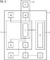
Das Röntgengerät
Auf dem Touchscreen
Eine Darstellung des Modells
In beiden Fällen ist eine mit durchbrochenen Linien gezeichnete Einhüllende
Das Modell
Die Positionsermittlung kann z.B. mit Hilfe optischer Sensoren erfolgen, wie beispielsweise einer Anzahl Laserscanner und 3D-Tiefenkameras und/oder stereoskopischen Navigationskameras. Auch andere Sensoren wie Ultraschallsensoren und kapazitive Näherungssensoren können herangezogen werden. Ferner ist eine Fusion der Raumerfassungsdaten mehrerer unabhängiger Sensor- und/oder Kamerasysteme möglich und vorteilhaft, da eine direkte Sichtlinie eines einzelnen Sensorsystems zur Überwachung der gesamten Raumgeometrie sehr unwahrscheinlich ist. Einzelheiten zu dem hier vorzugsweise zum Einsatz kommenden Verfahren zur Raumerfassung werden weiter unten beschrieben.The position determination may e.g. with the help of optical sensors, such as a number of laser scanners and 3D depth cameras and / or stereoscopic navigation cameras. Other sensors such as ultrasonic sensors and capacitive proximity sensors can be used. Furthermore, a merger of the spatial acquisition data of several independent sensor and / or camera systems is possible and advantageous since a direct line of sight of a single sensor system for monitoring the entire spatial geometry is very unlikely. Details of the method of space detection preferably used herein will be described below.
Neben dem Modell
Das Raummodell
Die Einteilung der Bodenfläche des Raummodells
Der Anwender kann nun eine oder mehrere verschiedene Zielpositionen
Ist eine Zielposition
Ist die Zielposition
Ist die Zielposition
Anschließend sind vorzugsweise zwei Möglichkeiten vorgesehen, wie das Röntgengerät
Bei dem Auslösemechanismus zum Auslösen des Fahrbefehls kann es sich z.B. um einen geeigneten Fußschalter oder eine beliebige Art von Fernbedienung, vorzugsweise jeweils mit Totmannfunktion, oder einen erstfehlersicheren Computer (Tablet, PC, Smartphone, ...) handeln. Die entsprechenden Prozesse und Vorrichtungen zur erstfehlersicheren Steuerung sind aus dem Stand der Technik bekannt. Die Vorrichtung zur Verwirklichung des Auslösemechanismus ist dabei ebenso wie der Touchscreen drahtgebunden oder drahtlos an die Auswerte- und Steuereinheit
Die Auswerte- und Steuereinheit
Mit der vorgeschlagenen Mensch-Maschine-Schnittstelle können Zielpositionen
Erkennt die Auswerte- und Steuereinheit
Vorzugsweise gilt für jeden Verfahrvorgang des mobilen Röntgengerätes
Für den Fall, dass mit dem Touchscreen
Positionsvorgaben für Zielpositionen
Ferner ist es auch möglich, eine Parkposition
Die Parkposition
Da die erkannte Raumgeometrie in der Regel einzigartig ist, kann man das Verfahren so nutzen, dass sich die Auswerte- und Steuereinheit
Das Landkartenprinzip kann auch zur Visualisierung bestimmter, vorherbestimmter Bewegungsmuster benutzt werden. Solche Bewegungsmuster können z.B. sein: ein Spiralscan (bzw. Pseudospiralscan im Fall eines C-Bogen-Röntgengerätes), ein Verfahren entlang einer definierten Bahnkurve zur Aufnahme mehrerer Röntgenbilder, eine Bewegung in eine zu einer vorherigen Aufnahme senkrechte Projektionsebene. Für solche Muster ist der Auswerte- und Steuereinheit
Die auf dem Touchscreen
Während bisher die eigentliche Positionsanzeige und Bewegungssteuerung des Röntgengerätes
In
Der Vorteil der Kombination mehrere Sensoren
Die hier verwendeten Sensoren
Mit den Sensoren
Bei den genannten 3D-Kameras
Die stationären Sensoren
Bei der Erstinbetriebnahme des mobilen Röntgengerätes
Mittels der stationären Sensoreinheiten
Sind keine stationären Sensoreinheiten
Die vorausgehende Beschreibung ist sinngemäß auf andere Medizingeräte mit mehreren räumlichen Bewegungsachsen bzw. Freiheitsgraden anwendbar, z.B. Radiographiegeräte.The foregoing description applies mutatis mutandis to other medical devices having multiple spatial axes of motion or degrees of freedom, e.g. Radiographiegeräte.
Obwohl die Erfindung im Detail durch das bevorzugte Ausführungsbeispiel näher illustriert und beschrieben wurde, so ist die Erfindung nicht auf die offenbarten Beispiele eingeschränkt und andere Variationen können vom Fachmann hieraus abgeleitet werden, ohne den Schutzumfang der Erfindung zu verlassen.Although the invention has been further illustrated and described in detail by the preferred embodiment, the invention is not limited to the disclosed examples, and other variations can be derived therefrom by those skilled in the art without departing from the scope of the invention.
BezugszeichenlisteLIST OF REFERENCE NUMBERS
- 1 1
- mobiles Medizingerät, C-Bogen-Röntgengerät mobile medical device, C-arm X-ray device
- 2 2
- Bewegungsmittel, Rad Moving means, wheel
- 3 3
- Antriebssteuerung drive control
- 4 4
- Antrieb drive
- 5 5
- zentrale Recheneinheit central processing unit
- 6 6
- Anzeigevorrichtung, Touchscreen Display device, touch screen
- 7 7
- Auswerte- und Steuereinheit Evaluation and control unit
- 8 8th
- Bedienoberfläche user interface
- 9 9
- Ist-Position Actual position
- 1010
- (frei) (free)
- 1111
- Modell des Röntgengerätes Model of the X-ray machine
- 1212
- Einhüllende envelope
- 1313
- Raummodell, Landkarte Room model, map
- 1414
- Raum, OP-Raum Room, operating room
- 1515
- Patiententisch patient table
- 1616
- Schrank cabinet
- 1717
- Medizingerät Medical device
- 1818
- erreichbarer Bereich reachable area
- 1919
- nicht erreichbarer Bereich unreachable area
- 2020
- (frei) (free)
- 2121
- Datenspeicher, Datei Data storage, file
- 2222
- Zielposition target position
- 2323
- Computermaus computer mouse
- 2424
- Weg, Route Way, route
- 2525
- alternativer Weg, Route alternative route, route
- 2626
- kollisionsvermeidender Weg, Route Collision avoiding way, route
- 2727
- Parkposition parking position
- 2828
- Kollisionsobjekt collision object
- 2929
- (frei) (free)
- 3030
- (frei) (free)
- 3131
- ortsfester Sensor, 3D-Kamera stationary sensor, 3D camera
- 3232
- mobiler Sensor, Laserscanner mobile sensor, laser scanner
- 3333
- Wand wall
- 3434
- Wandhalterung, Magnethalterung Wall bracket, magnetic bracket
- 2525
- Raumerfassungssystem Space acquisition system
- 3636
- Laserprojektor laser projector
Claims (10)
Translated fromGermanPriority Applications (2)
| Application Number | Priority Date | Filing Date | Title |
|---|---|---|---|
| DE102016209576.5ADE102016209576B4 (en) | 2016-06-01 | 2016-06-01 | Motion control for a mobile medical device |
| US15/610,686US10265035B2 (en) | 2016-06-01 | 2017-06-01 | Method and device for motion control of a mobile medical device |
Applications Claiming Priority (1)
| Application Number | Priority Date | Filing Date | Title |
|---|---|---|---|
| DE102016209576.5ADE102016209576B4 (en) | 2016-06-01 | 2016-06-01 | Motion control for a mobile medical device |
Publications (2)
| Publication Number | Publication Date |
|---|---|
| DE102016209576A1true DE102016209576A1 (en) | 2017-12-07 |
| DE102016209576B4 DE102016209576B4 (en) | 2024-06-13 |
Family
ID=60327693
Family Applications (1)
| Application Number | Title | Priority Date | Filing Date |
|---|---|---|---|
| DE102016209576.5AActiveDE102016209576B4 (en) | 2016-06-01 | 2016-06-01 | Motion control for a mobile medical device |
Country Status (2)
| Country | Link |
|---|---|
| US (1) | US10265035B2 (en) |
| DE (1) | DE102016209576B4 (en) |
Cited By (5)
| Publication number | Priority date | Publication date | Assignee | Title |
|---|---|---|---|---|
| EP3443908A1 (en)* | 2017-08-15 | 2019-02-20 | Siemens Healthcare GmbH | Method for operating an x-ray device comprising an articulated arm and x-ray device with an articulated arm |
| AT522753A1 (en)* | 2019-07-10 | 2021-01-15 | Trumpf Maschinen Austria Gmbh & Co Kg | Positioning method of an operating device in relation to a bending machine |
| EP3797677A1 (en)* | 2019-09-30 | 2021-03-31 | Siemens Healthcare GmbH | Mobile medical device and method and system for controlling the mobile medical device |
| DE102021210771A1 (en) | 2021-09-27 | 2023-03-30 | Siemens Healthcare Gmbh | Method for controlling a medical device and device |
| EP4342385A1 (en)* | 2022-09-26 | 2024-03-27 | Koninklijke Philips N.V. | Medical device movement control apparatus |
Families Citing this family (153)
| Publication number | Priority date | Publication date | Assignee | Title |
|---|---|---|---|---|
| US11871901B2 (en) | 2012-05-20 | 2024-01-16 | Cilag Gmbh International | Method for situational awareness for surgical network or surgical network connected device capable of adjusting function based on a sensed situation or usage |
| US11504192B2 (en) | 2014-10-30 | 2022-11-22 | Cilag Gmbh International | Method of hub communication with surgical instrument systems |
| DE102015008188B3 (en)* | 2015-06-25 | 2016-06-16 | Kuka Roboter Gmbh | Departure of a predetermined path with a robot |
| KR102471422B1 (en) | 2017-02-17 | 2022-11-30 | 엔제트 테크놀러지스 인크. | Method and system for non-contact control in surgical environment |
| US11564756B2 (en) | 2017-10-30 | 2023-01-31 | Cilag Gmbh International | Method of hub communication with surgical instrument systems |
| US11026687B2 (en) | 2017-10-30 | 2021-06-08 | Cilag Gmbh International | Clip applier comprising clip advancing systems |
| US11229436B2 (en) | 2017-10-30 | 2022-01-25 | Cilag Gmbh International | Surgical system comprising a surgical tool and a surgical hub |
| US11911045B2 (en) | 2017-10-30 | 2024-02-27 | Cllag GmbH International | Method for operating a powered articulating multi-clip applier |
| US11317919B2 (en) | 2017-10-30 | 2022-05-03 | Cilag Gmbh International | Clip applier comprising a clip crimping system |
| US11510741B2 (en) | 2017-10-30 | 2022-11-29 | Cilag Gmbh International | Method for producing a surgical instrument comprising a smart electrical system |
| US11801098B2 (en) | 2017-10-30 | 2023-10-31 | Cilag Gmbh International | Method of hub communication with surgical instrument systems |
| US11925373B2 (en) | 2017-10-30 | 2024-03-12 | Cilag Gmbh International | Surgical suturing instrument comprising a non-circular needle |
| US11311342B2 (en) | 2017-10-30 | 2022-04-26 | Cilag Gmbh International | Method for communicating with surgical instrument systems |
| US11291510B2 (en) | 2017-10-30 | 2022-04-05 | Cilag Gmbh International | Method of hub communication with surgical instrument systems |
| US11832840B2 (en) | 2017-12-28 | 2023-12-05 | Cilag Gmbh International | Surgical instrument having a flexible circuit |
| US11744604B2 (en) | 2017-12-28 | 2023-09-05 | Cilag Gmbh International | Surgical instrument with a hardware-only control circuit |
| US11304763B2 (en) | 2017-12-28 | 2022-04-19 | Cilag Gmbh International | Image capturing of the areas outside the abdomen to improve placement and control of a surgical device in use |
| US11786245B2 (en) | 2017-12-28 | 2023-10-17 | Cilag Gmbh International | Surgical systems with prioritized data transmission capabilities |
| US20190201090A1 (en) | 2017-12-28 | 2019-07-04 | Ethicon Llc | Capacitive coupled return path pad with separable array elements |
| US20190201142A1 (en) | 2017-12-28 | 2019-07-04 | Ethicon Llc | Automatic tool adjustments for robot-assisted surgical platforms |
| US12127729B2 (en) | 2017-12-28 | 2024-10-29 | Cilag Gmbh International | Method for smoke evacuation for surgical hub |
| US11633237B2 (en) | 2017-12-28 | 2023-04-25 | Cilag Gmbh International | Usage and technique analysis of surgeon / staff performance against a baseline to optimize device utilization and performance for both current and future procedures |
| US10918310B2 (en) | 2018-01-03 | 2021-02-16 | Biosense Webster (Israel) Ltd. | Fast anatomical mapping (FAM) using volume filling |
| US20190201112A1 (en) | 2017-12-28 | 2019-07-04 | Ethicon Llc | Computer implemented interactive surgical systems |
| US11132462B2 (en) | 2017-12-28 | 2021-09-28 | Cilag Gmbh International | Data stripping method to interrogate patient records and create anonymized record |
| US11389164B2 (en) | 2017-12-28 | 2022-07-19 | Cilag Gmbh International | Method of using reinforced flexible circuits with multiple sensors to optimize performance of radio frequency devices |
| US11559308B2 (en) | 2017-12-28 | 2023-01-24 | Cilag Gmbh International | Method for smart energy device infrastructure |
| US11026751B2 (en) | 2017-12-28 | 2021-06-08 | Cilag Gmbh International | Display of alignment of staple cartridge to prior linear staple line |
| US11364075B2 (en) | 2017-12-28 | 2022-06-21 | Cilag Gmbh International | Radio frequency energy device for delivering combined electrical signals |
| US11013563B2 (en) | 2017-12-28 | 2021-05-25 | Ethicon Llc | Drive arrangements for robot-assisted surgical platforms |
| US11160605B2 (en) | 2017-12-28 | 2021-11-02 | Cilag Gmbh International | Surgical evacuation sensing and motor control |
| US10892995B2 (en) | 2017-12-28 | 2021-01-12 | Ethicon Llc | Surgical network determination of prioritization of communication, interaction, or processing based on system or device needs |
| US11273001B2 (en) | 2017-12-28 | 2022-03-15 | Cilag Gmbh International | Surgical hub and modular device response adjustment based on situational awareness |
| US11304745B2 (en) | 2017-12-28 | 2022-04-19 | Cilag Gmbh International | Surgical evacuation sensing and display |
| US11304699B2 (en) | 2017-12-28 | 2022-04-19 | Cilag Gmbh International | Method for adaptive control schemes for surgical network control and interaction |
| US11324557B2 (en) | 2017-12-28 | 2022-05-10 | Cilag Gmbh International | Surgical instrument with a sensing array |
| US11179175B2 (en) | 2017-12-28 | 2021-11-23 | Cilag Gmbh International | Controlling an ultrasonic surgical instrument according to tissue location |
| WO2019133144A1 (en) | 2017-12-28 | 2019-07-04 | Ethicon Llc | Detection and escalation of security responses of surgical instruments to increasing severity threats |
| US11696760B2 (en) | 2017-12-28 | 2023-07-11 | Cilag Gmbh International | Safety systems for smart powered surgical stapling |
| US10892899B2 (en) | 2017-12-28 | 2021-01-12 | Ethicon Llc | Self describing data packets generated at an issuing instrument |
| US11069012B2 (en) | 2017-12-28 | 2021-07-20 | Cilag Gmbh International | Interactive surgical systems with condition handling of devices and data capabilities |
| US10944728B2 (en) | 2017-12-28 | 2021-03-09 | Ethicon Llc | Interactive surgical systems with encrypted communication capabilities |
| US11464535B2 (en) | 2017-12-28 | 2022-10-11 | Cilag Gmbh International | Detection of end effector emersion in liquid |
| US10943454B2 (en) | 2017-12-28 | 2021-03-09 | Ethicon Llc | Detection and escalation of security responses of surgical instruments to increasing severity threats |
| US11166772B2 (en) | 2017-12-28 | 2021-11-09 | Cilag Gmbh International | Surgical hub coordination of control and communication of operating room devices |
| US20190201039A1 (en) | 2017-12-28 | 2019-07-04 | Ethicon Llc | Situational awareness of electrosurgical systems |
| US11317937B2 (en) | 2018-03-08 | 2022-05-03 | Cilag Gmbh International | Determining the state of an ultrasonic end effector |
| US11234756B2 (en) | 2017-12-28 | 2022-02-01 | Cilag Gmbh International | Powered surgical tool with predefined adjustable control algorithm for controlling end effector parameter |
| US11857152B2 (en) | 2017-12-28 | 2024-01-02 | Cilag Gmbh International | Surgical hub spatial awareness to determine devices in operating theater |
| US11202570B2 (en) | 2017-12-28 | 2021-12-21 | Cilag Gmbh International | Communication hub and storage device for storing parameters and status of a surgical device to be shared with cloud based analytics systems |
| US11056244B2 (en) | 2017-12-28 | 2021-07-06 | Cilag Gmbh International | Automated data scaling, alignment, and organizing based on predefined parameters within surgical networks |
| US11076921B2 (en) | 2017-12-28 | 2021-08-03 | Cilag Gmbh International | Adaptive control program updates for surgical hubs |
| US10966791B2 (en) | 2017-12-28 | 2021-04-06 | Ethicon Llc | Cloud-based medical analytics for medical facility segmented individualization of instrument function |
| US11659023B2 (en) | 2017-12-28 | 2023-05-23 | Cilag Gmbh International | Method of hub communication |
| US10755813B2 (en) | 2017-12-28 | 2020-08-25 | Ethicon Llc | Communication of smoke evacuation system parameters to hub or cloud in smoke evacuation module for interactive surgical platform |
| US11419667B2 (en) | 2017-12-28 | 2022-08-23 | Cilag Gmbh International | Ultrasonic energy device which varies pressure applied by clamp arm to provide threshold control pressure at a cut progression location |
| US11571234B2 (en) | 2017-12-28 | 2023-02-07 | Cilag Gmbh International | Temperature control of ultrasonic end effector and control system therefor |
| US11410259B2 (en) | 2017-12-28 | 2022-08-09 | Cilag Gmbh International | Adaptive control program updates for surgical devices |
| US11291495B2 (en) | 2017-12-28 | 2022-04-05 | Cilag Gmbh International | Interruption of energy due to inadvertent capacitive coupling |
| US11786251B2 (en) | 2017-12-28 | 2023-10-17 | Cilag Gmbh International | Method for adaptive control schemes for surgical network control and interaction |
| US11179208B2 (en) | 2017-12-28 | 2021-11-23 | Cilag Gmbh International | Cloud-based medical analytics for security and authentication trends and reactive measures |
| US11864728B2 (en) | 2017-12-28 | 2024-01-09 | Cilag Gmbh International | Characterization of tissue irregularities through the use of mono-chromatic light refractivity |
| US10758310B2 (en) | 2017-12-28 | 2020-09-01 | Ethicon Llc | Wireless pairing of a surgical device with another device within a sterile surgical field based on the usage and situational awareness of devices |
| US11051876B2 (en) | 2017-12-28 | 2021-07-06 | Cilag Gmbh International | Surgical evacuation flow paths |
| US11464559B2 (en) | 2017-12-28 | 2022-10-11 | Cilag Gmbh International | Estimating state of ultrasonic end effector and control system therefor |
| US20190206569A1 (en) | 2017-12-28 | 2019-07-04 | Ethicon Llc | Method of cloud based data analytics for use with the hub |
| US11903601B2 (en) | 2017-12-28 | 2024-02-20 | Cilag Gmbh International | Surgical instrument comprising a plurality of drive systems |
| US11529187B2 (en) | 2017-12-28 | 2022-12-20 | Cilag Gmbh International | Surgical evacuation sensor arrangements |
| US11284936B2 (en) | 2017-12-28 | 2022-03-29 | Cilag Gmbh International | Surgical instrument having a flexible electrode |
| US11602393B2 (en) | 2017-12-28 | 2023-03-14 | Cilag Gmbh International | Surgical evacuation sensing and generator control |
| US11311306B2 (en) | 2017-12-28 | 2022-04-26 | Cilag Gmbh International | Surgical systems for detecting end effector tissue distribution irregularities |
| US11832899B2 (en) | 2017-12-28 | 2023-12-05 | Cilag Gmbh International | Surgical systems with autonomously adjustable control programs |
| US11969216B2 (en) | 2017-12-28 | 2024-04-30 | Cilag Gmbh International | Surgical network recommendations from real time analysis of procedure variables against a baseline highlighting differences from the optimal solution |
| US11540855B2 (en) | 2017-12-28 | 2023-01-03 | Cilag Gmbh International | Controlling activation of an ultrasonic surgical instrument according to the presence of tissue |
| US12396806B2 (en) | 2017-12-28 | 2025-08-26 | Cilag Gmbh International | Adjustment of a surgical device function based on situational awareness |
| US11432885B2 (en) | 2017-12-28 | 2022-09-06 | Cilag Gmbh International | Sensing arrangements for robot-assisted surgical platforms |
| US11969142B2 (en) | 2017-12-28 | 2024-04-30 | Cilag Gmbh International | Method of compressing tissue within a stapling device and simultaneously displaying the location of the tissue within the jaws |
| US12062442B2 (en) | 2017-12-28 | 2024-08-13 | Cilag Gmbh International | Method for operating surgical instrument systems |
| US10849697B2 (en) | 2017-12-28 | 2020-12-01 | Ethicon Llc | Cloud interface for coupled surgical devices |
| US11666331B2 (en) | 2017-12-28 | 2023-06-06 | Cilag Gmbh International | Systems for detecting proximity of surgical end effector to cancerous tissue |
| US11304720B2 (en) | 2017-12-28 | 2022-04-19 | Cilag Gmbh International | Activation of energy devices |
| US12376855B2 (en) | 2017-12-28 | 2025-08-05 | Cilag Gmbh International | Safety systems for smart powered surgical stapling |
| BR112020012801A2 (en)* | 2017-12-28 | 2020-11-24 | Ethicon Llc | spatial recognition of central surgical controllers in operating rooms |
| US11896322B2 (en) | 2017-12-28 | 2024-02-13 | Cilag Gmbh International | Sensing the patient position and contact utilizing the mono-polar return pad electrode to provide situational awareness to the hub |
| US11308075B2 (en) | 2017-12-28 | 2022-04-19 | Cilag Gmbh International | Surgical network, instrument, and cloud responses based on validation of received dataset and authentication of its source and integrity |
| US11257589B2 (en) | 2017-12-28 | 2022-02-22 | Cilag Gmbh International | Real-time analysis of comprehensive cost of all instrumentation used in surgery utilizing data fluidity to track instruments through stocking and in-house processes |
| US11109866B2 (en) | 2017-12-28 | 2021-09-07 | Cilag Gmbh International | Method for circular stapler control algorithm adjustment based on situational awareness |
| US11419630B2 (en)* | 2017-12-28 | 2022-08-23 | Cilag Gmbh International | Surgical system distributed processing |
| US11266468B2 (en) | 2017-12-28 | 2022-03-08 | Cilag Gmbh International | Cooperative utilization of data derived from secondary sources by intelligent surgical hubs |
| US12096916B2 (en) | 2017-12-28 | 2024-09-24 | Cilag Gmbh International | Method of sensing particulate from smoke evacuated from a patient, adjusting the pump speed based on the sensed information, and communicating the functional parameters of the system to the hub |
| US11424027B2 (en) | 2017-12-28 | 2022-08-23 | Cilag Gmbh International | Method for operating surgical instrument systems |
| US10987178B2 (en)* | 2017-12-28 | 2021-04-27 | Ethicon Llc | Surgical hub control arrangements |
| US11937769B2 (en) | 2017-12-28 | 2024-03-26 | Cilag Gmbh International | Method of hub communication, processing, storage and display |
| US11253315B2 (en) | 2017-12-28 | 2022-02-22 | Cilag Gmbh International | Increasing radio frequency to create pad-less monopolar loop |
| US11446052B2 (en) | 2017-12-28 | 2022-09-20 | Cilag Gmbh International | Variation of radio frequency and ultrasonic power level in cooperation with varying clamp arm pressure to achieve predefined heat flux or power applied to tissue |
| US11998193B2 (en) | 2017-12-28 | 2024-06-04 | Cilag Gmbh International | Method for usage of the shroud as an aspect of sensing or controlling a powered surgical device, and a control algorithm to adjust its default operation |
| US10898622B2 (en) | 2017-12-28 | 2021-01-26 | Ethicon Llc | Surgical evacuation system with a communication circuit for communication between a filter and a smoke evacuation device |
| US11818052B2 (en) | 2017-12-28 | 2023-11-14 | Cilag Gmbh International | Surgical network determination of prioritization of communication, interaction, or processing based on system or device needs |
| US11559307B2 (en) | 2017-12-28 | 2023-01-24 | Cilag Gmbh International | Method of robotic hub communication, detection, and control |
| US10695081B2 (en) | 2017-12-28 | 2020-06-30 | Ethicon Llc | Controlling a surgical instrument according to sensed closure parameters |
| US11147607B2 (en) | 2017-12-28 | 2021-10-19 | Cilag Gmbh International | Bipolar combination device that automatically adjusts pressure based on energy modality |
| US11612444B2 (en) | 2017-12-28 | 2023-03-28 | Cilag Gmbh International | Adjustment of a surgical device function based on situational awareness |
| US10932872B2 (en) | 2017-12-28 | 2021-03-02 | Ethicon Llc | Cloud-based medical analytics for linking of local usage trends with the resource acquisition behaviors of larger data set |
| US11278281B2 (en) | 2017-12-28 | 2022-03-22 | Cilag Gmbh International | Interactive surgical system |
| US11576677B2 (en) | 2017-12-28 | 2023-02-14 | Cilag Gmbh International | Method of hub communication, processing, display, and cloud analytics |
| US11096693B2 (en) | 2017-12-28 | 2021-08-24 | Cilag Gmbh International | Adjustment of staple height of at least one row of staples based on the sensed tissue thickness or force in closing |
| US11100631B2 (en)* | 2017-12-28 | 2021-08-24 | Cilag Gmbh International | Use of laser light and red-green-blue coloration to determine properties of back scattered light |
| US11896443B2 (en) | 2017-12-28 | 2024-02-13 | Cilag Gmbh International | Control of a surgical system through a surgical barrier |
| US11423007B2 (en) | 2017-12-28 | 2022-08-23 | Cilag Gmbh International | Adjustment of device control programs based on stratified contextual data in addition to the data |
| US11589888B2 (en) | 2017-12-28 | 2023-02-28 | Cilag Gmbh International | Method for controlling smart energy devices |
| US11376002B2 (en) | 2017-12-28 | 2022-07-05 | Cilag Gmbh International | Surgical instrument cartridge sensor assemblies |
| US11678881B2 (en) | 2017-12-28 | 2023-06-20 | Cilag Gmbh International | Spatial awareness of surgical hubs in operating rooms |
| US11551810B2 (en)* | 2018-01-03 | 2023-01-10 | Siemens Healthcare Gmbh | Method for acquiring and for altering a configuration of a number of objects in a procedure room and corresponding device |
| US11534196B2 (en) | 2018-03-08 | 2022-12-27 | Cilag Gmbh International | Using spectroscopy to determine device use state in combo instrument |
| US11986233B2 (en) | 2018-03-08 | 2024-05-21 | Cilag Gmbh International | Adjustment of complex impedance to compensate for lost power in an articulating ultrasonic device |
| US11259830B2 (en) | 2018-03-08 | 2022-03-01 | Cilag Gmbh International | Methods for controlling temperature in ultrasonic device |
| US12303159B2 (en) | 2018-03-08 | 2025-05-20 | Cilag Gmbh International | Methods for estimating and controlling state of ultrasonic end effector |
| US11213294B2 (en) | 2018-03-28 | 2022-01-04 | Cilag Gmbh International | Surgical instrument comprising co-operating lockout features |
| US11207067B2 (en) | 2018-03-28 | 2021-12-28 | Cilag Gmbh International | Surgical stapling device with separate rotary driven closure and firing systems and firing member that engages both jaws while firing |
| US10973520B2 (en) | 2018-03-28 | 2021-04-13 | Ethicon Llc | Surgical staple cartridge with firing member driven camming assembly that has an onboard tissue cutting feature |
| US11096688B2 (en) | 2018-03-28 | 2021-08-24 | Cilag Gmbh International | Rotary driven firing members with different anvil and channel engagement features |
| US11589865B2 (en) | 2018-03-28 | 2023-02-28 | Cilag Gmbh International | Methods for controlling a powered surgical stapler that has separate rotary closure and firing systems |
| US11219453B2 (en) | 2018-03-28 | 2022-01-11 | Cilag Gmbh International | Surgical stapling devices with cartridge compatible closure and firing lockout arrangements |
| US11278280B2 (en) | 2018-03-28 | 2022-03-22 | Cilag Gmbh International | Surgical instrument comprising a jaw closure lockout |
| US11090047B2 (en) | 2018-03-28 | 2021-08-17 | Cilag Gmbh International | Surgical instrument comprising an adaptive control system |
| US11471156B2 (en) | 2018-03-28 | 2022-10-18 | Cilag Gmbh International | Surgical stapling devices with improved rotary driven closure systems |
| JP7099941B2 (en)* | 2018-11-30 | 2022-07-12 | 富士フイルム株式会社 | How to operate a mobile radiographer, a mobile radiographer, and an operation program of a mobile radiographer |
| EP3662834A1 (en)* | 2018-12-07 | 2020-06-10 | Koninklijke Philips N.V. | Positioning a medical x-ray imaging apparatus |
| US20200201268A1 (en)* | 2018-12-19 | 2020-06-25 | Abb Schweiz Ag | System and method for guiding a sensor around an unknown scene |
| JP7162989B2 (en)* | 2019-02-04 | 2022-10-31 | 株式会社ミツトヨ | One-dimensional measuring machine and program |
| US11369377B2 (en) | 2019-02-19 | 2022-06-28 | Cilag Gmbh International | Surgical stapling assembly with cartridge based retainer configured to unlock a firing lockout |
| US11464511B2 (en) | 2019-02-19 | 2022-10-11 | Cilag Gmbh International | Surgical staple cartridges with movable authentication key arrangements |
| US11331100B2 (en) | 2019-02-19 | 2022-05-17 | Cilag Gmbh International | Staple cartridge retainer system with authentication keys |
| US11357503B2 (en) | 2019-02-19 | 2022-06-14 | Cilag Gmbh International | Staple cartridge retainers with frangible retention features and methods of using same |
| US11317915B2 (en) | 2019-02-19 | 2022-05-03 | Cilag Gmbh International | Universal cartridge based key feature that unlocks multiple lockout arrangements in different surgical staplers |
| WO2020233691A1 (en)* | 2019-05-21 | 2020-11-26 | Shanghai United Imaging Healthcare Co., Ltd. | Medical devices and control systems thereof |
| USD964564S1 (en) | 2019-06-25 | 2022-09-20 | Cilag Gmbh International | Surgical staple cartridge retainer with a closure system authentication key |
| USD950728S1 (en) | 2019-06-25 | 2022-05-03 | Cilag Gmbh International | Surgical staple cartridge |
| USD952144S1 (en) | 2019-06-25 | 2022-05-17 | Cilag Gmbh International | Surgical staple cartridge retainer with firing system authentication key |
| US10937218B2 (en)* | 2019-07-01 | 2021-03-02 | Microsoft Technology Licensing, Llc | Live cube preview animation |
| CN110647148B (en)* | 2019-09-19 | 2022-11-11 | 北京小狗吸尘器集团股份有限公司 | Wall position determining method and device, computer equipment and storage medium |
| DE102019125490A1 (en)* | 2019-09-23 | 2021-03-25 | Karl Storz Se & Co. Kg | Foot switches for medical devices |
| US12256293B2 (en)* | 2020-03-30 | 2025-03-18 | EMC IP Holding Company LLC | Increasing device data confidence and operation via temporal and spatial analytics |
| US11229410B2 (en) | 2020-06-08 | 2022-01-25 | Illinois Tool Works Inc. | Systems and methods to control radiation scanner positioning |
| CN111657984A (en)* | 2020-06-28 | 2020-09-15 | 南京安科医疗科技有限公司 | Movable CT device and control method thereof |
| WO2022028439A1 (en) | 2020-08-03 | 2022-02-10 | 上海联影医疗科技股份有限公司 | Medical device control method and system |
| CN112274166A (en)* | 2020-10-18 | 2021-01-29 | 上海联影医疗科技股份有限公司 | Control method, system and device of medical diagnosis and treatment equipment |
| CN112043300B (en)* | 2020-08-31 | 2023-10-20 | 上海西门子医疗器械有限公司 | Anti-collision device and method, and computer-readable storage medium |
| JP7471977B2 (en)* | 2020-09-25 | 2024-04-22 | キヤノンメディカルシステムズ株式会社 | Interference detection device and method |
| EP4221621A4 (en)* | 2020-09-30 | 2024-10-23 | Auris Health, Inc. | Collision avoidance in surgical robotics based on non-contact information |
| CN113456221B (en)* | 2021-06-30 | 2023-06-30 | 上海微创医疗机器人(集团)股份有限公司 | Positioning guiding method and system of movable equipment and surgical robot system |
| CN114767031B (en)* | 2022-03-31 | 2024-03-08 | 常州朗合医疗器械有限公司 | Endoscope apparatus, position guidance apparatus, system, method, and computer-readable storage medium for endoscope |
| CN115299974B (en)* | 2022-08-04 | 2025-02-28 | 上海联影医疗科技股份有限公司 | Slide rail CT interference inspection method, device, slide rail CT equipment and storage medium |
Citations (1)
| Publication number | Priority date | Publication date | Assignee | Title |
|---|---|---|---|---|
| WO2015068952A1 (en)* | 2013-11-08 | 2015-05-14 | Samsung Electronics Co., Ltd. | Method and apparatus for controlling movement of medical device |
- 2016
- 2016-06-01DEDE102016209576.5Apatent/DE102016209576B4/enactiveActive
- 2017
- 2017-06-01USUS15/610,686patent/US10265035B2/enactiveActive
Patent Citations (1)
| Publication number | Priority date | Publication date | Assignee | Title |
|---|---|---|---|---|
| WO2015068952A1 (en)* | 2013-11-08 | 2015-05-14 | Samsung Electronics Co., Ltd. | Method and apparatus for controlling movement of medical device |
Cited By (9)
| Publication number | Priority date | Publication date | Assignee | Title |
|---|---|---|---|---|
| EP3443908A1 (en)* | 2017-08-15 | 2019-02-20 | Siemens Healthcare GmbH | Method for operating an x-ray device comprising an articulated arm and x-ray device with an articulated arm |
| US11076818B2 (en) | 2017-08-15 | 2021-08-03 | Siemens Healthcare Gmbh | Method for operating an x-ray device with an articulated arm, and x-ray device with an articulated arm |
| AT522753A1 (en)* | 2019-07-10 | 2021-01-15 | Trumpf Maschinen Austria Gmbh & Co Kg | Positioning method of an operating device in relation to a bending machine |
| AT522753B1 (en)* | 2019-07-10 | 2021-12-15 | Trumpf Maschinen Austria Gmbh & Co Kg | Positioning method of an operating device with respect to a bending machine |
| EP3797677A1 (en)* | 2019-09-30 | 2021-03-31 | Siemens Healthcare GmbH | Mobile medical device and method and system for controlling the mobile medical device |
| DE102021210771A1 (en) | 2021-09-27 | 2023-03-30 | Siemens Healthcare Gmbh | Method for controlling a medical device and device |
| US12274572B2 (en) | 2021-09-27 | 2025-04-15 | Siemens Healthineers Ag | Mobile medical device including a LiDAR sensor and a method for controlling such a mobile medical device |
| EP4342385A1 (en)* | 2022-09-26 | 2024-03-27 | Koninklijke Philips N.V. | Medical device movement control apparatus |
| WO2024068273A1 (en)* | 2022-09-26 | 2024-04-04 | Koninklijke Philips N.V. | Medical device movement control apparatus |
Also Published As
| Publication number | Publication date |
|---|---|
| US10265035B2 (en) | 2019-04-23 |
| DE102016209576B4 (en) | 2024-06-13 |
| US20170347979A1 (en) | 2017-12-07 |
Similar Documents
| Publication | Publication Date | Title |
|---|---|---|
| DE102016209576B4 (en) | Motion control for a mobile medical device | |
| DE102015206158B4 (en) | Mobile C-arm system | |
| DE102018109463C5 (en) | Method for using a multi-unit actuated kinematics, preferably a robot, particularly preferably an articulated robot, by a user using a mobile display device | |
| EP3559769B1 (en) | Autonomous mobile robot and method for controlling an autonomous mobile robot | |
| EP1447770B1 (en) | Method and apparatus for visualization of computer-based information | |
| EP2764812B1 (en) | Cleaning robot | |
| EP2818954B1 (en) | Method for planning a virtual track, driverless transport vehicle with a controller to implement the corresponding track planning method | |
| EP3441840B1 (en) | Method for operating a self-propelled cleaning device | |
| DE102012207269A1 (en) | Method for operating driverless transport vehicle, involves automatically moving driverless transport vehicle along real track based on virtual track and determining current position of vehicle with respect to virtual map | |
| EP3709853A1 (en) | Floor treatment by means of an autonomous mobile robot | |
| EP3355147B1 (en) | Method for operating an automatically moving vehicle | |
| EP3901872A1 (en) | Method and device for controlling operation of construction machine | |
| EP1521211A2 (en) | Method and apparatus for determining the position and orientation of an image receiving device | |
| EP2990532B1 (en) | Self-propelled construction machine and method for the visualization of the processing environment of a construction machine moving in the terrain | |
| DE102017210221B4 (en) | Method for longitudinal and lateral guidance of a motor vehicle | |
| DE102014012825A1 (en) | Self-propelled construction machine and method for controlling a self-propelled construction machine | |
| EP3562730B1 (en) | Method for automated parking a vehicle | |
| DE102016204618A1 (en) | Mobile imaging device | |
| DE102008046348A1 (en) | Method for computer-assisted planning of path of C-arm in treatment room for patient, involves determining optimal set of paths corresponding to targets, where target is set as value of minimum total risk of collision | |
| WO2012013388A1 (en) | Parallel online-offline reconstruction for three-dimensional space measurement | |
| DE102021131060B3 (en) | System and method with a system | |
| EP3774499B1 (en) | Method for monitoring and controlling a remotely-controlled parking or maneuvering operation of a vehicle | |
| WO2023174872A1 (en) | Checking a safety configuration of a robot | |
| DE102021207088A1 (en) | working machine | |
| DE102010021042A1 (en) | Method for computer-assisted controlling of vehicle, particularly driverless transport vehicle, involves fitting laser scanner in vehicle, where measured value tuple is detected by laser scanner in scanner layer |
Legal Events
| Date | Code | Title | Description |
|---|---|---|---|
| R012 | Request for examination validly filed | ||
| R016 | Response to examination communication | ||
| R081 | Change of applicant/patentee | Owner name:SIEMENS HEALTHINEERS AG, DE Free format text:FORMER OWNER: SIEMENS HEALTHCARE GMBH, MUENCHEN, DE | |
| R018 | Grant decision by examination section/examining division | ||
| R020 | Patent grant now final |