DE102016209001A1 - Holding device for a light emitting diode and for a lens and method for adjustment - Google Patents
Holding device for a light emitting diode and for a lens and method for adjustmentDownload PDFInfo
- Publication number
- DE102016209001A1 DE102016209001A1DE102016209001.1ADE102016209001ADE102016209001A1DE 102016209001 A1DE102016209001 A1DE 102016209001A1DE 102016209001 ADE102016209001 ADE 102016209001ADE 102016209001 A1DE102016209001 A1DE 102016209001A1
- Authority
- DE
- Germany
- Prior art keywords
- sleeve
- holding device
- lens
- ring element
- holding
- Prior art date
- Legal status (The legal status is an assumption and is not a legal conclusion. Google has not performed a legal analysis and makes no representation as to the accuracy of the status listed.)
- Withdrawn
Links
- 238000000034methodMethods0.000titleclaimsdescription8
- 238000003466weldingMethods0.000claimsdescription16
- 241000219739LensSpecies0.000description23
- 230000005855radiationEffects0.000description19
- 238000006243chemical reactionMethods0.000description8
- 238000006073displacement reactionMethods0.000description7
- 230000005284excitationEffects0.000description7
- OAICVXFJPJFONN-UHFFFAOYSA-NPhosphorusChemical compound[P]OAICVXFJPJFONN-UHFFFAOYSA-N0.000description5
- 230000003287optical effectEffects0.000description3
- 230000003068static effectEffects0.000description3
- 241000209035IlexSpecies0.000description2
- 238000005516engineering processMethods0.000description2
- 240000004322Lens culinarisSpecies0.000description1
- 230000015572biosynthetic processEffects0.000description1
- 229910019990cerium-doped yttrium aluminum garnetInorganic materials0.000description1
- 230000003750conditioning effectEffects0.000description1
- 230000003247decreasing effectEffects0.000description1
- 230000001419dependent effectEffects0.000description1
- 238000005286illuminationMethods0.000description1
- 238000004519manufacturing processMethods0.000description1
- 238000004886process controlMethods0.000description1
- 230000003595spectral effectEffects0.000description1
- 229910019655synthetic inorganic crystalline materialInorganic materials0.000description1
Images
Classifications
- F—MECHANICAL ENGINEERING; LIGHTING; HEATING; WEAPONS; BLASTING
- F21—LIGHTING
- F21V—FUNCTIONAL FEATURES OR DETAILS OF LIGHTING DEVICES OR SYSTEMS THEREOF; STRUCTURAL COMBINATIONS OF LIGHTING DEVICES WITH OTHER ARTICLES, NOT OTHERWISE PROVIDED FOR
- F21V14/00—Controlling the distribution of the light emitted by adjustment of elements
- F21V14/06—Controlling the distribution of the light emitted by adjustment of elements by movement of refractors
- F—MECHANICAL ENGINEERING; LIGHTING; HEATING; WEAPONS; BLASTING
- F21—LIGHTING
- F21V—FUNCTIONAL FEATURES OR DETAILS OF LIGHTING DEVICES OR SYSTEMS THEREOF; STRUCTURAL COMBINATIONS OF LIGHTING DEVICES WITH OTHER ARTICLES, NOT OTHERWISE PROVIDED FOR
- F21V17/00—Fastening of component parts of lighting devices, e.g. shades, globes, refractors, reflectors, filters, screens, grids or protective cages
- F21V17/02—Fastening of component parts of lighting devices, e.g. shades, globes, refractors, reflectors, filters, screens, grids or protective cages with provision for adjustment
- F—MECHANICAL ENGINEERING; LIGHTING; HEATING; WEAPONS; BLASTING
- F21—LIGHTING
- F21V—FUNCTIONAL FEATURES OR DETAILS OF LIGHTING DEVICES OR SYSTEMS THEREOF; STRUCTURAL COMBINATIONS OF LIGHTING DEVICES WITH OTHER ARTICLES, NOT OTHERWISE PROVIDED FOR
- F21V19/00—Fastening of light sources or lamp holders
- F—MECHANICAL ENGINEERING; LIGHTING; HEATING; WEAPONS; BLASTING
- F21—LIGHTING
- F21Y—INDEXING SCHEME ASSOCIATED WITH SUBCLASSES F21K, F21L, F21S and F21V, RELATING TO THE FORM OR THE KIND OF THE LIGHT SOURCES OR OF THE COLOUR OF THE LIGHT EMITTED
- F21Y2115/00—Light-generating elements of semiconductor light sources
- F21Y2115/30—Semiconductor lasers
Landscapes
- Engineering & Computer Science (AREA)
- General Engineering & Computer Science (AREA)
- Semiconductor Lasers (AREA)
Abstract
Translated fromGermanDescription
Translated fromGermanDie Erfindung geht aus von einer Haltevorrichtung zum Haltern einer lichtemittierenden Laserdiode (LD) und einer Linse. Des Weiteren geht die Erfindung aus von einer Leuchtanordnung mit einer derartigen Haltevorrichtung und außerdem von einem Verfahren zur Justage einer derartigen Leuchtanordnung.The invention is based on a holding device for holding a light-emitting laser diode (LD) and a lens. Furthermore, the invention is based on a lighting arrangement with such a holding device and also on a method for adjusting such a lighting arrangement.
Aus dem Stand der Technik ist die Laser-Activated-Remote-Phosphor(LARP)-Technologie bekannt. Bei dieser Technologie wird ein von der Strahlungsquelle beabstandet angeordnetes Konversionselement, das Leuchtstoff aufweist oder daraus besteht, mit Anregungsstrahlung, insbesondere einem Anregungsstrahl (Pumpstrahl, Pumplaserstrahl), bestrahlt. Die Anregungsstrahlung des Anregungsstrahls wird vom Leuchtstoff absorbiert und zumindest teilweise in eine Konversionsstrahlung (Emissionsstrahlung) umgewandelt, deren Wellenlängen und somit spektralen Eigenschaften und/oder Farbe durch die Konversionseigenschaften des Leuchtstoffs bestimmt wird. Beispielsweise kann so mit Hilfe des Konversionselements blaue Anregungsstrahlung (blaues Laserlicht) in rote oder grüne oder gelbe Konversionsstrahlung (Konversionslicht, Beleuchtungslicht) konvertiert werden.From the prior art, the laser-activated remote phosphor (LARP) technology is known. In this technology, a conversion element arranged at a distance from the radiation source and comprising or consisting of phosphor is irradiated with excitation radiation, in particular an excitation beam (pump beam, pump laser beam). The excitation radiation of the excitation beam is absorbed by the phosphor and at least partially converted into a conversion radiation (emission radiation) whose wavelengths and thus spectral properties and / or color are determined by the conversion properties of the phosphor. For example, with the aid of the conversion element, blue excitation radiation (blue laser light) can be converted into red or green or yellow conversion radiation (conversion light, illumination light).
Konversionslicht und gegebenenfalls unkonvertiertes Anregungslicht bilden das Nutzlicht. Beispielsweise im Falle der Verwendung einer blauen Laserdiode, mit einer Anregungsstrahlung im Wellenlängenbereich von etwa 440 bis 470 nm, und eines gelben Leuchtstoffkonverters, beispielsweise aus Cer-dotiertem Yttrium-Aluminium-Granat, also Ce:YAG, ergibt sich mit abnehmenden Zumischungsanteil einer unkonvertierten Laserstrahlung zum Konversionslicht ein bläuliches, weiß-bläuliches, weißes, weiß-gelbliches oder gelbes Nutzlicht.Conversion light and possibly unconverted excitation light form the useful light. For example, in the case of using a blue laser diode, with an excitation radiation in the wavelength range of about 440 to 470 nm, and a yellow phosphor converter, for example of cerium-doped yttrium-aluminum garnet, so Ce: YAG, results with decreasing Zumischungsanteil an unconverted laser radiation for conversion light a bluish, white-bluish, white, white-yellowish or yellow useful light.
Des Weiteren sind aus dem Stand der Technik statische LARP-Systeme im Automotive-Bereich bekannt, die mit einer hohen Leuchtdichte Licht großflächig und mit einem großen Abstand zum die Strahlung abgebenden Fahrzeug auf die Straße projizieren. Hierbei werden Strahlungen von mehreren Strahlungsquellen (Laserlichtquellen) zusammengeführt und vermischt. Anforderungen an eine Justage sind bei einem statischen LARP-System geringer als bei einem dynamischen LARP-System. Um Justage-Ungenauigkeiten auszugleichen, können bei einem statischen LARP-System einfach Blenden angeordnet und eingesetzt werden. Bei einem dynamischen LARP-System dagegen ist es erforderlich, dass Strahlungen oder Strahlbündel der einzelnen Kanäle oder Strahlungsquellen sehr präzise zueinander angeordnet sind. Optische Verluste durch Blenden oder eine Überlagerung von Strahlungen der Strahlungsquellen oder Kanäle zum Bildaufbau sollen hierbei vermieden werden.Furthermore, static LARP systems in the automotive sector are known from the state of the art, which project light onto the road with a high luminance over a large area and at a great distance from the radiation-emitting vehicle. Here, radiations from several radiation sources (laser light sources) are brought together and mixed. Adjustment requirements are lower for a static LARP system than for a dynamic LARP system. To compensate for adjustment inaccuracies, can be easily arranged and used in a static LARP system screens. In contrast, in a dynamic LARP system it is necessary that the radiation or beam of the individual channels or radiation sources are arranged very precisely relative to one another. Optical losses due to diaphragms or a superposition of radiations of the radiation sources or channels for image formation should be avoided.
Die Aufgabe der vorliegenden Erfindung ist es, eine Haltevorrichtung für eine Laserdiode (LD) und für eine Linse und eine Leuchtanordnung zu schaffen, mit der auf vorrichtungstechnisch einfache Weise eine hohe Genauigkeit erzielbar ist. Des Weiteren ist es die Aufgabe der Erfindung, ein Verfahren zur Justage der Leuchtanordnung zu schaffen, mit dem auf einfache Weise und geringem Aufwand eine Relativanordnung der Linse zur LD einstellbar ist.The object of the present invention is to provide a holding device for a laser diode (LD) and for a lens and a lighting arrangement with which a high accuracy can be achieved in a device-technically simple manner. Furthermore, it is the object of the invention to provide a method for adjusting the lighting arrangement, with which a relative arrangement of the lens to LD can be adjusted in a simple manner and with little effort.
Die Aufgabe hinsichtlich der Haltevorrichtung wird gelöst gemäß den Merkmalen des Anspruchs 1, hinsichtlich der Leuchtanordnung gemäß den Merkmalen des Anspruchs 10 und hinsichtlich des Verfahrens gemäß den Merkmalen des Anspruchs 13.The object with regard to the holding device is achieved according to the features of claim 1, with respect to the lighting arrangement according to the features of
Besonders vorteilhafte Ausgestaltungen finden sich in den abhängigen Ansprüchen.Particularly advantageous embodiments can be found in the dependent claims.
Erfindungsgemäß ist eine Haltevorrichtung oder ein Submount für eine lichtemittierende Laserdiode (LD), insbesondere für eine blaue Laserdiode, und für eine Linse vorgesehen. Die Haltevorrichtung weist ein Ringelement auf, in das die Linse fest einsetzbar ist. Des Weiteren ist eine Hülse vorgesehen, in der das Ringelement axial verschiebbar angeordnet ist und festlegbar ist. Des Weiteren kann an der Hülse die LD anordbar und festlegbar sein. Vorteilhafterweise ist in der Hülse eine Längsachse des Ringelements relativ zu einer Längsachse der Hülse verschwenkbar.According to the invention, a holding device or a submount is provided for a light-emitting laser diode (LD), in particular for a blue laser diode, and for a lens. The holding device has a ring element into which the lens is firmly inserted. Furthermore, a sleeve is provided, in which the ring element is arranged axially displaceable and can be fixed. Furthermore, the LD can be arranged and fixable on the sleeve. Advantageously, in the sleeve, a longitudinal axis of the ring member is pivotable relative to a longitudinal axis of the sleeve.
Diese Lösung hat den Vorteil, dass die Kombination des Ringelements und der Hülse zu einer einfachen Justage der Linse führt, in dem diese in Richtung ihrer Längsachse, was beispielsweise einer z-Richtung entspricht, relativ zur LD fokussiert werden kann. Durch die Verschwenkbarkeit kann das Ringelement des Weiteren vorteilhafterweise in zwei Ebenen getaumelt werden. Nach der Justage kann das Ringelement einfach festgelegt werden.This solution has the advantage that the combination of the ring element and the sleeve leads to a simple adjustment of the lens, in which it can be focused relative to the LD in the direction of its longitudinal axis, which corresponds for example to a z-direction. Due to the pivotability, the ring element can furthermore advantageously be staggered in two planes. After adjustment, the ring element can be easily fixed.
In weiter Ausgestaltung der Erfindung ist ein Halteelement vorgesehen, an dem die LD festlegbar ist. Für das Halteelement kann die Hülse eine Anlagefläche aufweisen, an der wiederum das Halteelement mit einer Anlagefläche anlegbar ist. Die Anlageflächen erstrecken sich vorzugsweise etwa senkrecht zur Längsachse der Hülse. Hierdurch ist eine passgenaue Verschiebung des Halteelements zusammen mit der LD in einer Verschiebeebene ermöglicht, die sich relativ zur Längsachse der Hülse erstreckt.In a further embodiment of the invention, a holding element is provided, on which the LD can be fixed. For the retaining element, the sleeve may have a contact surface, on which in turn the retaining element can be applied with a contact surface. The contact surfaces preferably extend approximately perpendicular to the longitudinal axis of the sleeve. As a result, a precisely fitting displacement of the holding element is made possible together with the LD in a displacement plane which extends relative to the longitudinal axis of the sleeve.
Mit anderen Worten ist durch die Haltevorrichtung ein aktives Ausrichten der, insbesondere asphärischen Linse in Bezug auf einen Strahlungspunkt oder „Beam-Point“ der Laserdiode in fünf Freiheitsgraden ermöglicht, womit sichergestellt ist, dass ein Strahlenbündel der Laserdiode in einer „Fast-“ und „Slow-Axis“ den simulierten optischen Anforderungen (Zentrierung, Fokussierung und Clipping) entspricht. Die fünf Freiheitsgrade sind hierbei die Verschiebung des Halteelements entlang der Anlagefläche (x- und y-Richtung), die Verschiebung des Ringelements in Längsrichtung (z-Richtung) und das taumeln des Ringelements in zwei Ebenen. Durch die Haltevorrichtung mit dem Ringelement und dem Haltelement können diese Elemente zusammen mit der Hülse nun in fünf Freiheitsgraden in eine optimale Position auf einfache Weise justiert werden. Eine geforderte Präzision im µm-Bereich ist hierdurch ermöglicht.In other words, by the holding device, an active alignment of the, in particular aspherical lens with respect to a radiation point or "beam point" of the laser diode in five Degrees of freedom is possible, which ensures that a beam of the laser diode in a "fast" and "slow axis" corresponds to the simulated optical requirements (centering, focusing and clipping). The five degrees of freedom here are the displacement of the holding element along the abutment surface (x and y direction), the displacement of the ring element in the longitudinal direction (z direction) and the tumbling of the ring element in two planes. Due to the holding device with the ring element and the holding element, these elements can now be adjusted together with the sleeve in five degrees of freedom in an optimal position in a simple manner. A required precision in the μm range is thereby made possible.
Vorzugsweise ist das Haltelement vorrichtungstechnisch einfach ringförmig ausgestaltet, um die LD aufzunehmen, in dem die LD in das Halteelement zumindest abschnittsweise eingesetzt ist. Über das Halteelement kann dann ein Strahlengang einer Strahlung der LD in die Hülse und durch die Linse führen.Preferably, the holding element is simply designed in terms of device design in a ring shape in order to receive the LD, in which the LD is inserted into the holding element at least in sections. About the holding element can then lead a beam path of radiation of the LD in the sleeve and through the lens.
Die Anlagefläche des Halteelements und der Hülse sind jeweils vorzugsweise als Ringfläche ausgebildet, womit bei einer Verschiebung des Halteelements entlang der Anlagefläche die LD weiter in die Hülse Strahlung emittieren kann.The contact surface of the holding element and the sleeve are each preferably designed as an annular surface, whereby with a displacement of the holding element along the contact surface, the LD can emit radiation into the sleeve further.
Das Halteelement kann einen ersten etwa kreisringförmigen Abschnitt und einen sich daran anschließenden zweiten etwa kreisringförmigen Abschnitt aufweisen, der dann vorzugsweise einen größeren Außendurchmesser hat. Durch die gestuften Abschnitte ist eine vereinfachte Handhabung, beispielsweise bei einem Einsatz eines Montagewerkzeugs, ermöglicht. Des Weiteren ist denkbar, dass am Halteelement eine Referenzierung vorgesehen ist. Beispielsweise könnte am zweiten Abschnitt als Referenzierung eine äußere Abflachung ausgebildet sein.The holding element may have a first approximately annular portion and an adjoining second approximately annular portion, which then preferably has a larger outer diameter. The stepped sections enable simplified handling, for example when using an assembly tool. Furthermore, it is conceivable that a referencing is provided on the holding element. For example, an outer flattening could be formed on the second section as referencing.
Mit Vorteil liegt das Ringelement mit seiner Außenmantelfläche an einer Innenmantelfläche der Hülse an. Das Ringelement ist dabei derart ausgestaltet, dass die Anlage in den gewünschten Verschwenkwinkeln vorherrscht. Als Anlage zwischen dem Ringelement und der Hülse kann beispielsweise ein Linienkontakt, insbesondere ein in Umfangsrichtung geschlossener Linienkontakt, vorgesehen sein.Advantageously, the ring element lies with its outer circumferential surface on an inner circumferential surface of the sleeve. The ring element is designed such that the system prevails in the desired pivoting angles. As a contact between the ring member and the sleeve, for example, a line contact, in particular a circumferentially closed line contact, may be provided.
Damit das Ringelement auf vorrichtungstechnische einfache Weise in der Hülse anliegt, ist eine Außenmantelfläche des Ringelements beispielsweise ballig ausgebildet. Insbesondere kann die Außenmantelfläche als Kugelringfläche ausgebildet sein, womit auf vorrichtungstechnisch einfache Weise das Ringelement beim Verschwenken in Anlage zur Hülse verbleibt. Weiter vorzugsweise ist das Ringelement metallisch ausgestaltet, wodurch es robust ist und mit einer hohen Genauigkeit fertigbar ist.So that the ring element rests on device-simple manner in the sleeve, an outer circumferential surface of the ring member is formed, for example, crowned. In particular, the outer circumferential surface may be formed as a ball ring surface, which remains on device-simple manner, the ring member during pivoting in contact with the sleeve. Further preferably, the ring element is metallic, whereby it is robust and can be manufactured with high accuracy.
In weiter Ausgestaltung der Erfindung kann die Innenmantelfläche der Hülse gestuft ausgebildet sein. Hierbei kann eine erste Stufe für die Anordnung des Ringelements und eine zweite, einen kleineren Durchmesser aufweisende Stufe vorgesehen sein, wobei die zweite Stufe dann vorteilhafterweise eine Verschiebung des Ringelements in Längsrichtung begrenzt. Die zweite Stufe erstreckt sich beispielsweise ausgehend von der Anlagefläche für das Halteelement.In a further embodiment of the invention, the inner circumferential surface of the sleeve may be formed stepped. Here, a first stage for the arrangement of the ring member and a second, having a smaller diameter stage may be provided, wherein the second stage then advantageously limits a displacement of the ring member in the longitudinal direction. The second stage extends, for example, starting from the contact surface for the holding element.
Vorzugsweise hat die Hülse einen Radialbund, der einen Abschnitt der Anlagefläche zur Anlage des Halteelements bildet. Durch den Radialbund ist somit eine verbreiterte Anlagefläche bei der Hülse ermöglicht. Des Weiteren kann der Radialbund einen Anschlag bilden, wenn die Haltevorrichtung mit der Hülse in eine entsprechende Aufnahme eines Gehäuses eingesetzt wird.Preferably, the sleeve has a radial collar which forms a portion of the contact surface for abutment of the holding element. The radial collar thus allows a widened contact surface in the sleeve. Furthermore, the radial collar can form a stop when the holding device with the sleeve is inserted into a corresponding receptacle of a housing.
In weiterer Ausgestaltung der Erfindung kann in die Hülse zumindest eine Längsnut eingebracht sein. Diese erstreckt sich vorzugsweise ausgehend von einer von der Anlagefläche wegweisenden Stirnfläche der Hülse, oder alternativ von der Anlagefläche aus. Hierdurch kann beispielsweise mit einem Werkzeug auf das Ringelement zugegriffen werden, wenn sich dieses in der Hülse befindet. Die Längsnut erstreckt sich beispielsweise parallel zur Längsachse der Hülse. Denkbar ist zwei oder drei oder mehr Längsnuten einzubringen, die sich dann ebenfalls etwa parallel zur Längsachse erstrecken können. Des Weiteren können die zwei, drei oder mehr Längsnuten etwa auf einem Teilkreis angeordnet sein. Bei der Hülse mit Radialbund erstreckt sich die Längsnut oder erstrecken sich die Längsnuten vorzugsweise etwa bis zum Radialbund der Hülse.In a further embodiment of the invention, at least one longitudinal groove can be introduced into the sleeve. This preferably extends from an end face of the sleeve facing away from the contact surface, or alternatively from the contact surface. As a result, for example, be accessed with a tool on the ring member, if this is located in the sleeve. The longitudinal groove extends, for example, parallel to the longitudinal axis of the sleeve. It is conceivable to introduce two or three or more longitudinal grooves, which can then likewise extend approximately parallel to the longitudinal axis. Furthermore, the two, three or more longitudinal grooves may be arranged approximately on a pitch circle. In the sleeve with radial collar extends the longitudinal groove or extend the longitudinal grooves preferably approximately up to the radial collar of the sleeve.
Vorzugsweise kann die Hülse mit dem Ringelement und/oder mit dem Halteelement fest verbunden sein. Die Verbindung erfolgt beispielsweise auf vorrichtungstechnische einfache Weise über Schweißen oder Laserschweißen.Preferably, the sleeve can be firmly connected to the ring element and / or with the holding element. The connection is made, for example, on device-technical simple way by welding or laser welding.
Erfindungsgemäß ist eine Leuchtanordnung mit einer Haltevorrichtung gemäß einem oder mehrerer der vorhergehenden Aspekte vorgesehen, die eine LD und eine Linse aufweist.According to the invention, a lighting arrangement is provided with a holding device according to one or more of the preceding aspects, comprising an LD and a lens.
Vorzugsweise ist die LD in das Haltelement und die Linse in das Ringelement fest eingesetzt, wodurch diese dann über die Haltevorrichtung einfach relativ zueinander justierbar sind. Die LD ist beispielsweise in das Halteelement mit geringem vorrichtungstechnischen Aufwand eingepresst oder über eine Presspassung darin eingesetzt. Eine Lichtaußenfläche der LD kann dann zur Hülse weisen. Bei der Linse handelt es sich vorzugsweise um eine asphärische Linse.Preferably, the LD is firmly inserted into the holding element and the lens in the ring element, whereby they are then easily adjustable relative to each other on the holding device. The LD is, for example, pressed into the holding element with little device complexity or inserted via a press fit therein. A light outer surface of the LD may then face the sleeve. at the lens is preferably an aspherical lens.
Bei dem erfindungsgemäßen Verfahren zur Justage einer Leuchtanordnung gemäß einem oder mehrerer der vorhergehenden Aspekte sind vorteilhafterweise folgende Schritte vorgesehen:
- – Verschwenken der Längsachse des Ringelements relativ zur Längsachse der Hülse zur Justage der Linse relativ zur LD,
- – Festlegen des Ringelements in der Hülse, insbesondere durch Schweißen oder insbesondere durch Laserschweißen oder insbesondere durch Punktschweißen (insbesondere mit einem Laser).
- Pivoting the longitudinal axis of the ring element relative to the longitudinal axis of the sleeve for adjusting the lens relative to the LD,
- - Fixing the ring element in the sleeve, in particular by welding or in particular by laser welding or in particular by spot welding (in particular with a laser).
Weiter vorzugsweise kann ein Verschieben des Halteelements entlang der Anlagefläche der Hülse zur Justage der LD und ein anschließendes Festlegen des Halteelements, insbesondere durch Schweißen, insbesondere durch Laserschweißen oder Punktschweißen (insbesondere mit einem Laser) erfolgen. Die Justage des Ringelements und des Halteelements erfolgt beispielsweise gleichzeitig oder die Justagen überschneiden sich zeitlich oder erfolgen zeitlich direkt hintereinander oder zeitlich versetzt. Das Festlegen des Ringelements und des Halteelements an der Hülse kann entweder gleichzeitig, im Wesentlichen gleichzeitig oder direkt hintereinander oder zeitlich versetzt zueinander erfolgen.Further preferably, a displacement of the holding element along the contact surface of the sleeve for adjusting the LD and a subsequent setting of the holding element, in particular by welding, in particular by laser welding or spot welding (in particular with a laser). The adjustment of the ring member and the retaining element takes place for example at the same time or the adjustments overlap in time or take place temporally directly behind one another or offset in time. The fixing of the ring element and the retaining element on the sleeve can be done either simultaneously, substantially simultaneously or directly one behind the other or offset in time.
Mit anderen Worten wird mit der beschriebenen Justagestrategie das Ziel einer senkrechten Abstrahlachse bezogen auf eine Referenzebene der Laserdiode und einer minimalen Profilverformung sichergestellt. Damit ist es möglich, eine geforderte hohe Präzision zu erreichen und optische Konzepte für ein scannendes, dynamisches automotive LARP-System umzusetzen.In other words, the aim of a vertical emission axis with respect to a reference plane of the laser diode and a minimum profile deformation is ensured with the adjustment strategy described. This makes it possible to achieve the required high precision and implement optical concepts for a scanning, dynamic automotive LARP system.
Wie vorstehend bereits erläutert, ist das Festlegen des Ringelements und/oder des Halteelements vorzugsweise unmittelbar nach der Justage vorgesehen. Das Schweißen oder Laserschweißen erfolgt vorzugsweise mit möglichst kleinen Spots. Mit anderen Worten soll das Schweißen oder Laserschweißen ohne Verzug mit möglichst kleinen Spots erfolgen, was vorteilhaft bei einer Umsetzung in einer Serienfertigung mit hoher Stückzahl und stabiler Prozessführung, insbesondere im Vergleich zum Kleben, auch vorteilhaft ist. Durch den Aufbau eines dynamischen LARP-Moduls aus Untereinheiten – wobei eine Untereinheit die Leuchtanordnung oder die Laserdiode-Submount ist – kann kostenintensiver Ausschuss, beispielsweise durch Zentrierfehler und daraus resultierender geringer Strahlungsemission, früh erkannt und ein Schaden somit minimiert werden.As already explained above, the fixing of the ring element and / or the retaining element is preferably provided immediately after the adjustment. The welding or laser welding is preferably carried out with the smallest possible spots. In other words, the welding or laser welding should be done without delay with the smallest possible spots, which is advantageous in an implementation in a mass production with high quantities and stable process control, especially in comparison with bonding, also advantageous. By building a dynamic LARP module of subunits - a subunit being the light assembly or the laser diode submount - costly rejects, such as centering errors and resulting low radiation emission, can be detected early and damage thus minimized.
Die Anmelderin behält sich vor ein Gehäuse zur Aufnahme der Leuchtanordnung gemäß einem oder mehrerer der vorhergehenden Aspekte zu beanspruchen. In dem Gehäuse kann eine, insbesondere zylindrische Aufnahme ausgebildet sein, in die die Hülse zumindest abschnittsweise einsetzbar ist.The applicant reserves the right to claim a housing for receiving the lighting arrangement according to one or more of the preceding aspects. In the housing may be formed, in particular a cylindrical receptacle into which the sleeve is at least partially used.
Im Folgenden soll die Erfindung anhand eines Ausführungsbeispiels näher erläutert werden. Die Figuren zeigen:In the following, the invention will be explained in more detail with reference to an embodiment. The figures show:
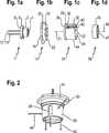
In
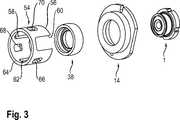
Gemäß
Gemäß
Gemäß
Gemäß
Gemäß
Offenbart ist eine Haltevorrichtung für eine lichtemittierende Laserdiode und für eine Linse, wobei die Haltevorrichtung eine Hülse hat, in der ein Ringelement, in das die Linse einsetzbar ist, vorgesehen ist, wobei das Ringelement in der Hülse axial verschiebbar und verschwenkbar und festlegbar ist.Disclosed is a holding device for a light emitting laser diode and a lens, wherein the holding device has a sleeve in which a ring member into which the lens is inserted, is provided, wherein the ring member in the sleeve is axially displaceable and pivotable and fixable.
BezugszeichenlisteLIST OF REFERENCE NUMBERS
- 11
- Laserdiodelaser diode
- 22
- Abschnittsection
- 44
- LichtaustrittsseiteLight output side
- 66
- Abschnittsection
- 8 8th
- Kontaktierungsseitecontacting side
- 1010
- Stromzuführungpower supply
- 1212
- Stromzuführungpower supply
- 1414
- Halteelementretaining element
- 1616
- Abschnittsection
- 1818
- Abschnittsection
- 2020
- Abflachungflattening
- 2222
- Anlageflächecontact surface
- 2424
- Hülseshell
- 2626
- Anlageflächecontact surface
- 2828
- Radialbundradial collar
- 3030
- Abschnittsection
- 3232
- Stirnflächeface
- 3434
- Stufestep
- 3636
- Stufestep
- 3838
- Ringelementring element
- 4040
- Längsnutlongitudinal groove
- 4242
- Längsnutlongitudinal groove
- 4444
- Längsnutlongitudinal groove
- 4646
- AußenmantelflächeOuter casing surface
- 4747
- Linselens
- 4848
- x-Richtungx-direction
- 4949
- Längsachselongitudinal axis
- 5050
- y-Richtungy-direction
- 5151
- Längsachselongitudinal axis
- 5252
- z-Richtungz-direction
- 5454
- Hülseshell
- 5656
- Anlageflächecontact surface
- 5858
- Längsnutlongitudinal groove
- 6060
- Längsnutlongitudinal groove
- 6262
- Längsnutlongitudinal groove
- 6464
- Stirnflächeface
- 6666
- Fensterwindow
- 6868
- Fensterwindow
- 7070
- Fensterwindow
Claims (15)
Translated fromGermanPriority Applications (2)
| Application Number | Priority Date | Filing Date | Title |
|---|---|---|---|
| DE102016209001.1ADE102016209001A1 (en) | 2016-05-24 | 2016-05-24 | Holding device for a light emitting diode and for a lens and method for adjustment |
| CN201720424625.XUCN206890104U (en) | 2016-05-24 | 2017-04-21 | Holding meanss and lighting device for light emitting diode and lens |
Applications Claiming Priority (1)
| Application Number | Priority Date | Filing Date | Title |
|---|---|---|---|
| DE102016209001.1ADE102016209001A1 (en) | 2016-05-24 | 2016-05-24 | Holding device for a light emitting diode and for a lens and method for adjustment |
Publications (1)
| Publication Number | Publication Date |
|---|---|
| DE102016209001A1true DE102016209001A1 (en) | 2017-11-30 |
Family
ID=60268623
Family Applications (1)
| Application Number | Title | Priority Date | Filing Date |
|---|---|---|---|
| DE102016209001.1AWithdrawnDE102016209001A1 (en) | 2016-05-24 | 2016-05-24 | Holding device for a light emitting diode and for a lens and method for adjustment |
Country Status (2)
| Country | Link |
|---|---|
| CN (1) | CN206890104U (en) |
| DE (1) | DE102016209001A1 (en) |
Cited By (3)
| Publication number | Priority date | Publication date | Assignee | Title |
|---|---|---|---|---|
| DE102017223369A1 (en)* | 2017-12-20 | 2019-06-27 | Osram Gmbh | PROCESS, ADJUSTMENT DEVICE AND DIODE DEVICE |
| DE102020210845A1 (en) | 2020-08-27 | 2022-03-03 | Siemens Energy Global GmbH & Co. KG | Microlens array and microoptical device |
| DE102021201606A1 (en) | 2021-02-19 | 2022-08-25 | Osram Gmbh | ATTACHMENT FOR A LASER MODULE HAVING A LASER DIODE AND METHOD FOR MANUFACTURING THE LASER MODULE |
Citations (5)
| Publication number | Priority date | Publication date | Assignee | Title |
|---|---|---|---|---|
| EP1441334A2 (en)* | 2003-01-22 | 2004-07-28 | Matsushita Electric Industrial Co., Ltd. | Optical head, optical information recording/reproducing apparatus, computer, video recording/reproducing apparatus, server and car navigation system |
| DE102004057732A1 (en)* | 2003-12-02 | 2005-08-04 | Fujitsu Limited, Kawasaki | Imaging device, manufacturing method therefor and holding mechanism therefor |
| US20070189765A1 (en)* | 2003-12-17 | 2007-08-16 | Hella Kgaa Hueck & Co. | Camera array and method for adjusting a lens with respect to the image sensor |
| KR20120095634A (en)* | 2011-02-21 | 2012-08-29 | 한국건설기술연구원 | Optical-glass lens for electronic display board and led electronic display board using the same |
| US20140003062A1 (en)* | 2012-06-27 | 2014-01-02 | Kenichi Yoshimura | Light source unit |
- 2016
- 2016-05-24DEDE102016209001.1Apatent/DE102016209001A1/ennot_activeWithdrawn
- 2017
- 2017-04-21CNCN201720424625.XUpatent/CN206890104U/ennot_activeExpired - Fee Related
Patent Citations (5)
| Publication number | Priority date | Publication date | Assignee | Title |
|---|---|---|---|---|
| EP1441334A2 (en)* | 2003-01-22 | 2004-07-28 | Matsushita Electric Industrial Co., Ltd. | Optical head, optical information recording/reproducing apparatus, computer, video recording/reproducing apparatus, server and car navigation system |
| DE102004057732A1 (en)* | 2003-12-02 | 2005-08-04 | Fujitsu Limited, Kawasaki | Imaging device, manufacturing method therefor and holding mechanism therefor |
| US20070189765A1 (en)* | 2003-12-17 | 2007-08-16 | Hella Kgaa Hueck & Co. | Camera array and method for adjusting a lens with respect to the image sensor |
| KR20120095634A (en)* | 2011-02-21 | 2012-08-29 | 한국건설기술연구원 | Optical-glass lens for electronic display board and led electronic display board using the same |
| US20140003062A1 (en)* | 2012-06-27 | 2014-01-02 | Kenichi Yoshimura | Light source unit |
Cited By (4)
| Publication number | Priority date | Publication date | Assignee | Title |
|---|---|---|---|---|
| DE102017223369A1 (en)* | 2017-12-20 | 2019-06-27 | Osram Gmbh | PROCESS, ADJUSTMENT DEVICE AND DIODE DEVICE |
| DE102020210845A1 (en) | 2020-08-27 | 2022-03-03 | Siemens Energy Global GmbH & Co. KG | Microlens array and microoptical device |
| DE102021201606A1 (en) | 2021-02-19 | 2022-08-25 | Osram Gmbh | ATTACHMENT FOR A LASER MODULE HAVING A LASER DIODE AND METHOD FOR MANUFACTURING THE LASER MODULE |
| DE102021201606B4 (en) | 2021-02-19 | 2022-10-06 | Osram Gmbh | ATTACHMENT FOR A LASER MODULE HAVING A LASER DIODE AND METHOD FOR MANUFACTURING THE LASER MODULE |
Also Published As
| Publication number | Publication date |
|---|---|
| CN206890104U (en) | 2018-01-16 |
Similar Documents
| Publication | Publication Date | Title |
|---|---|---|
| EP2491629B1 (en) | Manufacturing method of a laser device | |
| EP2693108B1 (en) | Light module and method of manufacturing the light module | |
| EP2693106A2 (en) | Light module | |
| DE102016209001A1 (en) | Holding device for a light emitting diode and for a lens and method for adjustment | |
| DE102015226633A1 (en) | Lighting device with a semiconductor laser and a lens device | |
| EP2966490A1 (en) | Device for generating light with several wavelengths, method for manufacturing a device, use of a positioning module, method for combining light rays and device for generating light with several wavelengths | |
| DE102018106504A1 (en) | TO package and method for its production | |
| DE212015000312U1 (en) | Joining device for connecting at least two components by means of an auxiliary joining part and laser welding | |
| DE202014001375U1 (en) | lighting device | |
| DE102017101008A1 (en) | MODULE, SET OF POSITIONING ELEMENTS, ARRANGEMENT WITH A MODULE, HEADLIGHTS AND METHOD FOR MANUFACTURING A MODULE | |
| EP3190617B1 (en) | Light emitting device and method of fabricating a light emitting device | |
| DE102021201606B4 (en) | ATTACHMENT FOR A LASER MODULE HAVING A LASER DIODE AND METHOD FOR MANUFACTURING THE LASER MODULE | |
| DE102015226636A1 (en) | LIGHTING DEVICE WITH LASER DIODE AND TRANSDUCER | |
| DE102018122264A1 (en) | LASER WELDING DEVICE AND METHOD FOR PRODUCTION OF COMPONENT | |
| EP1053576B1 (en) | Method for constructing and connecting optical components, especially optical components in a laser resonator, and a laser resonator | |
| DE102015113562A1 (en) | Converter heatsink assembly with metallic solder connection | |
| EP3769135A1 (en) | Method for centering optical elements | |
| EP3789659A2 (en) | Base for a light conversion or illumination device | |
| WO2012007326A2 (en) | Structural element for an injection valve with two connected components | |
| DE102018209300A1 (en) | BEAM COMBINER WITH ONE-PIECE, SPLASHED HOUSING; AS WELL AS HEADLIGHTS | |
| DE102015204817A1 (en) | Conversion device for converting radiation, luminaire arrangement and method for producing a conversion device | |
| DE102016207780A1 (en) | Radiation combining apparatus and method of making a combiner | |
| DE102022214346B3 (en) | Laser device and method for assembling the same | |
| WO2020083668A1 (en) | Illumination device for vehicles | |
| EP3757446A1 (en) | Light module, in particular for a motor vehicle |
Legal Events
| Date | Code | Title | Description |
|---|---|---|---|
| R163 | Identified publications notified | ||
| R005 | Application deemed withdrawn due to failure to request examination |