DE102016207666A1 - Medical smoke evacuation apparatus and method of operating the same - Google Patents
Medical smoke evacuation apparatus and method of operating the sameDownload PDFInfo
- Publication number
- DE102016207666A1 DE102016207666A1DE102016207666.3ADE102016207666ADE102016207666A1DE 102016207666 A1DE102016207666 A1DE 102016207666A1DE 102016207666 ADE102016207666 ADE 102016207666ADE 102016207666 A1DE102016207666 A1DE 102016207666A1
- Authority
- DE
- Germany
- Prior art keywords
- flue gas
- supply channel
- measured value
- particle
- filter
- Prior art date
- Legal status (The legal status is an assumption and is not a legal conclusion. Google has not performed a legal analysis and makes no representation as to the accuracy of the status listed.)
- Granted
Links
- 238000000034methodMethods0.000titleclaimsabstractdescription20
- 239000000779smokeSubstances0.000titleclaimsdescription44
- 239000003546flue gasSubstances0.000claimsabstractdescription317
- UGFAIRIUMAVXCW-UHFFFAOYSA-NCarbon monoxideChemical compound[O+]#[C-]UGFAIRIUMAVXCW-UHFFFAOYSA-N0.000claimsabstractdescription290
- 239000002245particleSubstances0.000claimsabstractdescription134
- 230000001419dependent effectEffects0.000claimsdescription14
- 230000003287optical effectEffects0.000claimsdescription14
- 238000010521absorption reactionMethods0.000claimsdescription11
- 230000036962time dependentEffects0.000claimsdescription11
- 230000001105regulatory effectEffects0.000claimsdescription5
- 238000005259measurementMethods0.000abstractdescription8
- 230000008859changeEffects0.000description7
- 238000000605extractionMethods0.000description7
- 239000003517fumeSubstances0.000description7
- 238000004599local-density approximationMethods0.000description5
- 230000008901benefitEffects0.000description4
- 238000001514detection methodMethods0.000description4
- 230000004913activationEffects0.000description3
- 238000004364calculation methodMethods0.000description3
- 238000007796conventional methodMethods0.000description3
- 239000007789gasSubstances0.000description3
- 238000010972statistical evaluationMethods0.000description3
- 238000001356surgical procedureMethods0.000description3
- 238000011144upstream manufacturingMethods0.000description3
- 238000004140cleaningMethods0.000description2
- OKTJSMMVPCPJKN-UHFFFAOYSA-NCarbonChemical compound[C]OKTJSMMVPCPJKN-UHFFFAOYSA-N0.000description1
- 230000006978adaptationEffects0.000description1
- 238000013459approachMethods0.000description1
- 230000033228biological regulationEffects0.000description1
- 229910052799carbonInorganic materials0.000description1
- 230000015271coagulationEffects0.000description1
- 238000005345coagulationMethods0.000description1
- 230000007423decreaseEffects0.000description1
- 230000000694effectsEffects0.000description1
- 230000036541healthEffects0.000description1
- 231100000206health hazardToxicity0.000description1
- 238000012423maintenanceMethods0.000description1
- 230000008569processEffects0.000description1
- 229920006395saturated elastomerPolymers0.000description1
- 239000000126substanceSubstances0.000description1
- 239000002341toxic gasSubstances0.000description1
- 238000002604ultrasonographyMethods0.000description1
Images
Classifications
- A—HUMAN NECESSITIES
- A61—MEDICAL OR VETERINARY SCIENCE; HYGIENE
- A61M—DEVICES FOR INTRODUCING MEDIA INTO, OR ONTO, THE BODY; DEVICES FOR TRANSDUCING BODY MEDIA OR FOR TAKING MEDIA FROM THE BODY; DEVICES FOR PRODUCING OR ENDING SLEEP OR STUPOR
- A61M1/00—Suction or pumping devices for medical purposes; Devices for carrying-off, for treatment of, or for carrying-over, body-liquids; Drainage systems
- A—HUMAN NECESSITIES
- A61—MEDICAL OR VETERINARY SCIENCE; HYGIENE
- A61B—DIAGNOSIS; SURGERY; IDENTIFICATION
- A61B18/00—Surgical instruments, devices or methods for transferring non-mechanical forms of energy to or from the body
- A—HUMAN NECESSITIES
- A61—MEDICAL OR VETERINARY SCIENCE; HYGIENE
- A61B—DIAGNOSIS; SURGERY; IDENTIFICATION
- A61B2218/00—Details of surgical instruments, devices or methods for transferring non-mechanical forms of energy to or from the body
- A61B2218/001—Details of surgical instruments, devices or methods for transferring non-mechanical forms of energy to or from the body having means for irrigation and/or aspiration of substances to and/or from the surgical site
- A61B2218/007—Aspiration
- A61B2218/008—Aspiration for smoke evacuation
- A—HUMAN NECESSITIES
- A61—MEDICAL OR VETERINARY SCIENCE; HYGIENE
- A61M—DEVICES FOR INTRODUCING MEDIA INTO, OR ONTO, THE BODY; DEVICES FOR TRANSDUCING BODY MEDIA OR FOR TAKING MEDIA FROM THE BODY; DEVICES FOR PRODUCING OR ENDING SLEEP OR STUPOR
- A61M2205/00—General characteristics of the apparatus
- A61M2205/33—Controlling, regulating or measuring
- A61M2205/3306—Optical measuring means
- A—HUMAN NECESSITIES
- A61—MEDICAL OR VETERINARY SCIENCE; HYGIENE
- A61M—DEVICES FOR INTRODUCING MEDIA INTO, OR ONTO, THE BODY; DEVICES FOR TRANSDUCING BODY MEDIA OR FOR TAKING MEDIA FROM THE BODY; DEVICES FOR PRODUCING OR ENDING SLEEP OR STUPOR
- A61M2205/00—General characteristics of the apparatus
- A61M2205/42—Reducing noise
- A—HUMAN NECESSITIES
- A61—MEDICAL OR VETERINARY SCIENCE; HYGIENE
- A61M—DEVICES FOR INTRODUCING MEDIA INTO, OR ONTO, THE BODY; DEVICES FOR TRANSDUCING BODY MEDIA OR FOR TAKING MEDIA FROM THE BODY; DEVICES FOR PRODUCING OR ENDING SLEEP OR STUPOR
- A61M2205/00—General characteristics of the apparatus
- A61M2205/75—General characteristics of the apparatus with filters
- A61M2205/7581—General characteristics of the apparatus with filters with means for switching over to a fresh filter on clogging or saturation
Landscapes
- Health & Medical Sciences (AREA)
- Life Sciences & Earth Sciences (AREA)
- Heart & Thoracic Surgery (AREA)
- Public Health (AREA)
- Veterinary Medicine (AREA)
- Engineering & Computer Science (AREA)
- Biomedical Technology (AREA)
- Surgery (AREA)
- General Health & Medical Sciences (AREA)
- Animal Behavior & Ethology (AREA)
- Molecular Biology (AREA)
- Medical Informatics (AREA)
- Nuclear Medicine, Radiotherapy & Molecular Imaging (AREA)
- Otolaryngology (AREA)
- Vascular Medicine (AREA)
- Anesthesiology (AREA)
- Hematology (AREA)
- Ventilation (AREA)
- Sampling And Sample Adjustment (AREA)
Abstract
Translated fromGermanDescription
Translated fromGermanDie Erfindung betrifft eine medizinische Rauchgasabsaugvorrichtung mit einem Fördermittel, einem Rauchgaszufuhrkanal und einem Rauchgasfilter, wobei das Fördermittel dazu eingerichtet ist, medizinische Rauchgase aus einem Operationsfeld abzusaugen, durch den Rauchgaszufuhrkanal zu fördern und dem Rauchgasfilter zuzuführen. Ferner betrifft die Erfindung ein Verfahren zum Betreiben einer medizinischen Rauchgasabsaugvorrichtung, die ein Fördermittel, einen Rauchgaszufuhrkanal und einen Rauchgasfilter umfasst, wobei das Fördermittel medizinische Rauchgase aus einem Operationsfeld absaugt, durch den Rauchgaszufuhrkanal fördert und dem Rauchgasfilter zuführt.The invention relates to a medical Rauchgasabsaugvorrichtung with a conveyor, a flue gas supply channel and a flue gas filter, wherein the conveying means is adapted to suck medical flue gases from an operating field to promote through the flue gas supply channel and the flue gas filter. Furthermore, the invention relates to a method for operating a medical Rauchgasabsaugvorrichtung comprising a conveyor, a flue gas supply channel and a flue gas filter, wherein the conveyor sucks medical flue gases from an operating field, through the flue gas supply channel and feeds the flue gas filter.
Kommt bei einem chirurgischen Eingriff ein elektrochirurgisches Instrument (HF-Instrument), ein Instrument, welches Mikrowellen oder Ultraschall einsetzt, oder ein Laser zum Schneiden oder Koagulieren zum Einsatz, entstehen durch die thermischen Prozesse am Gewebe chirurgische bzw. medizinische Rauchgase. Diese enthalten unterschiedliche Stoffe, vielfach in Form kleiner Partikel, die eine unerwünschte Gesundheitsgefährdung für den Patienten und das OP-Personal darstellen. Ferner haben die medizinischen Rauchgase aufgrund der enthaltenen toxischen Gase vielfach einen unangenehmen Geruch. Um die negativen Folgen für Patient und Personal zu minimieren, werden Rauchgasabsaugvorrichtungen eingesetzt.If an electrosurgical instrument (HF instrument), an instrument that uses microwaves or ultrasound, or a laser for cutting or coagulation are used during a surgical procedure, surgical or medical flue gases are produced by the thermal processes on the tissue. These contain different substances, often in the form of small particles, which pose an undesirable health hazard for the patient and the surgical staff. Furthermore, the medical flue gases often have an unpleasant odor due to the toxic gases contained. In order to minimize the negative consequences for patient and staff, smoke evacuation devices are used.
Die Rausgasabsaugvorrichtung trägt jedoch nicht unerheblich zum Geräuschpegel im Operationssaal bei. Daher werden die medizinischen Rauchgasabsaugvorrichtungen nur dann aktiviert, wenn tatsächlich auch medizinische Rauchgase abgesaugt werden. Die Aktivierung erfolgt beispielsweise durch manuelle Betätigung direkt am Gerät oder mit einem Fußschalter, der an geeigneter Position platziert ist. Es ist auch bekannt, die Rauchgasabsaugvorrichtung mit dem elektrochirurgischen Instrument zu synchronisieren. Beispielsweise wird induktiv der Strom erfasst, der von einer Versorgungseinheit eines elektrochirurgischen Instruments (auch als ESU bezeichnet, für engl. „electrosurgical unit“) zu dem Handinstrument durch eine Versorgungsleitung fließt. Diese Art der Erkennung, wann das elektrochirurgische Instrument aktiviert wird, funktioniert jedoch bei abgeschirmten Kabeln nicht. Es ist ferner möglich, einen Aktivierungs-Signalton zu detektieren, welcher von der elektrochirurgischen Versorgungseinheit abgegeben wird, wenn das elektrochirurgische Instrument aktiviert wird. Die Signaltöne sind jedoch nicht bei jeder Einheit gleich, so dass keine universell anwendbare Lösung gefunden werden kann. Außerdem können Nebengeräusche diese Art der Erkennung stören. Eine weitere Möglichkeit besteht darin, die Versorgungseinheit des elektrochirurgischen Instruments über ein Zwischenmodul an die Stromversorgung anzuschließen. Aus dem Messwert für den aktuell verbrauchten Strom des elektrochirurgischen Generators wird auf dessen Aktivierung geschlossen.However, the Rausgasabsaugvorrichtung contributes significantly to the noise level in the operating room. Therefore, the medical Rauchgasabsaugvorrichtungen be activated only when in fact medical smoke gases are sucked. The activation takes place for example by manual operation directly on the device or with a foot switch, which is placed in a suitable position. It is also known to synchronize the smoke evacuation device with the electrosurgical instrument. For example, the current is detected inductively, which flows from a supply unit of an electrosurgical instrument (also known as ESU for "electrosurgical unit") to the hand instrument through a supply line. However, this type of detection when the electrosurgical instrument is activated does not work with shielded cables. It is also possible to detect an activation beep which is emitted by the electrosurgical supply unit when the electrosurgical instrument is activated. However, the beeps are not the same for each unit, so no universally applicable solution can be found. In addition, background noise can interfere with this type of detection. Another possibility is to connect the supply unit of the electrosurgical instrument via an intermediate module to the power supply. From the measured value for the currently consumed current of the electrosurgical generator is closed on its activation.
Da jedoch keine einheitliche Stecker-Norm vorhanden ist und außerdem die elektrochirurgischen Versorgungseinheiten in einem vorgegebenen Leistungsbereich arbeiten müssten, ist auch dieser technische Ansatz nicht universell anwendbar.However, since there is no uniform plug standard and also the electrosurgical supply units would have to operate in a predetermined power range, this technical approach is not universally applicable.
Die während des aktiven Betriebs der Rauchgasabsaugvorrichtung eingesaugten Rauchgase enthalten Rauchgaspartikel, die beispielsweise in Kohlefiltern oder in ULPA-Filtern (von engl. „ultra low penetration air“) aufgefangen werden. Solche Absorptionsfilter müssen regelmäßig ausgetauscht werden, um eine ausreichende Reinigungswirkung bei dem erforderlichen Durchfluss des abgesaugten Rauchgases stets bereitzustellen. Die Filterlebensdauer wird vielfach über die Einsatzzeit des Filters bestimmt. Es ist ebenso bekannt, die Lebensdauer des Filters über den Durchfluss zu bestimmen. Hat die medizinische Rauchgasabsaugvorrichtung also ein bestimmtes Volumen abgesaugt, wird ein Signal ausgegeben, welches zum Filterwechsel auffordert.The flue gases sucked in during the active operation of the flue gas extraction device contain flue gas particles which are collected, for example, in carbon filters or in ULPA filters ("ultra low-penetration air"). Such absorption filters must be replaced regularly in order to always provide a sufficient cleaning effect at the required flow rate of the extracted flue gas. Filter life is often determined over the life of the filter. It is also known to determine the life of the filter across the flow. If the medical smoke evacuation device has therefore sucked off a certain volume, a signal is output which requests the filter change.
Es ist eine Aufgabe der Erfindung, eine medizinische Rauchgasabsaugvorrichtung sowie ein Verfahren zum Betreiben einer medizinischen Rauchgasabsaugvorrichtung anzugeben, welche zumindest gegenüber einigen der im Stand der Technik bekannten technischen Probleme verbessert ist.It is an object of the invention to provide a medical fume extraction apparatus and method for operating a medical fume extraction apparatus which is at least improved over some of the technical problems known in the art.
Die Aufgabe wird gelöst durch eine medizinische Rauchgasabsaugvorrichtung mit einem Fördermittel, einem Rauchgaszufuhrkanal und einem Rauchgasfilter, wobei das Fördermittel dazu eingerichtet ist, medizinische Rauchgase aus einem Operationsfeld abzusaugen, durch den Rauchgaszufuhrkanal zu fördern und dem Rauchgasfilter zuzuführen, wobei die medizinische Rauchgasabsaugvorrichtung dadurch fortgebildet ist, dass eine Steuereinrichtung und ein Rauchgaspartikeldetektor umfasst sind, wobei die Steuereinrichtung dazu eingerichtet ist, das Fördermittel so zu steuern oder zu regeln, dass dieses dauerhaft in einer Bereitschaftsstufe betrieben wird, in der das Fördermittel die Rauchgase in dem Rauchgaszufuhrkanal mit einer ersten Flussrate fördert, wobei der Rauchgaspartikeldetektor dazu eingerichtet ist, einen Rauchgasmesswert zu erfassen und der Steuereinrichtung bereitzustellen, wobei der Rauchgasmesswert eine in dem durch den Rauchgaszufuhrkanal geförderten Rauchgas enthaltene Rauchgaspartikelkonzentration und/oder eine Rauchgaspartikelgröße charakterisiert.The object is achieved by a medical Rauchgasabsaugvorrichtung with a conveyor, a flue gas supply channel and a flue gas filter, wherein the conveyor is adapted to suck medical flue gases from an operating field to promote through the flue gas supply channel and the flue gas filter, wherein the medical Rauchgasabsaugvorrichtung is thereby developed, in that a control device and a flue gas particle detector are included, wherein the control device is set up to control the conveyor so that it is permanently operated in a standby stage in which the conveyor conveys the flue gases in the flue gas supply channel at a first flow rate the flue gas particle detector is adapted to detect a flue gas measurement value and to provide it to the control device, wherein the flue gas measurement value comprises a flue gas contained in the flue gas conveyed through the flue gas feed channel particle concentration and / or a flue gas particle size.
Die medizinische Rauchgasabsaugvorrichtung gemäß Aspekten der Erfindung saugt dauerhaft und mit geringer Saugkraft bzw. Förderleistung Luft und falls vorhanden auch darin enthaltenes medizinisches Rauchgas aus dem Operationsfeld ein. Sie wird dabei mit so geringer Saug- bzw. Förderleistung betrieben, dass ihr Geräuschpegel insbesondere unterhalb eines vorgegebenen Grenzwertes liegt. Zumindest aber ist die Geräuschemission der Rauchgasabsaugvorrichtung so gering, dass sie von dem Benutzer, beispielsweise dem OP-Personal, nicht als störend empfunden wird. Entsteht nun während eines chirurgischen Eingriffs medizinisches Rauchgas, so gelangt dieses aufgrund der kontinuierlich stattfindenden Absaugung in die medizinische Rauchgasabsaugvorrichtung. Der Rauchgaspartikeldetektor misst eine Rauchgaspartikelkonzentration und/oder eine Rauchgaspartikelgröße in dem Rauchgaszufuhrkanal vorhandenen Rauchgas. Dieser Rauchgasmesswert dient als Ausgangspunkt für verschiedene Funktionalitäten der Rauchgasabsaugvorrichtung.The medical Rauchgasabsaugvorrichtung according to aspects of the invention sucks permanently and with low suction or air flow and, if present, medical flue gas contained therein from the surgical field. It is operated with so low suction or flow rate that their noise level is in particular below a predetermined limit. But at least the noise emission of Rauchgasabsaugvorrichtung is so low that it is not bothersome by the user, such as the surgical staff. Emerges now during a surgical procedure medical flue gas, this gets into the medical Rauchgasabsaugvorrichtung due to the continuous suction. The flue gas particle detector measures a flue gas particle concentration and / or a flue gas particle size in flue gas present in the flue gas feed channel. This flue gas reading serves as a starting point for various functionalities of the smoke evacuation device.
Beispielsweise wird gemäß einer Ausführungsform eine Förderleistung des Fördermittels, welche die Flussrate des durch den Rauchgaszufuhrkanal geförderten Rauchgases bestimmt, in Abhängigkeit von dem Rauchgasmesswert gesteuert und/oder geregelt. Die Steuereinrichtung der Rauchgasabsaugvorrichtung ist entsprechend eingerichtet.For example, according to one embodiment, a delivery rate of the conveying means, which determines the flow rate of the flue gas conveyed through the flue gas supply channel, is controlled and / or regulated in dependence on the flue gas measured value. The control device of the smoke evacuation device is set up accordingly.
So ist es insbesondere vorgesehen, dass die Steuereinrichtung dazu eingerichtet ist, das Fördermittel in der Bereitschaftsstufe und in zumindest einer Leistungsstufe zu betreiben, wobei, wenn das Fördermittel in der Leistungsstufe betrieben wird, die Rauchgase in dem Rauchgaszufuhrkanal mit einer zweiten Flussrate gefördert werden, die höher ist als die erste Flussrate, und wobei die Steuereinrichtung dazu eingerichtet ist, das Fördermittel von der Bereitschaftsstufe in die Leistungsstufe zu versetzen, wenn der Rauchgasmesswert einen vorgegebenen Grenzwert überschreitet.Thus, it is provided in particular that the control device is adapted to operate the conveyor in the standby stage and in at least one power stage, wherein when the conveyor is operated in the power stage, the flue gases are conveyed in the flue gas supply channel with a second flow rate is higher than the first flow rate, and wherein the control means is adapted to move the conveyor from the standby stage to the power stage when the flue gas reading exceeds a predetermined threshold.
Es ist selbstverständlich ebenso vorgesehen, dass, wenn der Rauchgasmesswert, insbesondere die Rauchgaspartikelkonzentration, (erneut) unter den vorgegebenen Grenzwert sinkt, die Förderleistung des Fördermittels zurück in die Bereitschaftsstufe versetzt wird.It is of course also provided that, when the flue gas measured value, in particular the flue gas particle concentration (again) drops below the predetermined limit, the delivery rate of the conveyor is returned to the standby stage.
Mit anderen Worten wird also anhand des Rauchanteils und/oder anhand der Rauchgaspartikelgröße in der abgesaugten Luft automatisch die Saugkraft der Rauchgasabsaugvorrichtung angepasst, um so eine optimale Absaugung der medizinischen Rauchgase zu gewährleisten. Neben einer stufenweisen Anpassung der Förderleistung ist ebenso eine stufenlose Anpassung der Förderleistung der Rauchgasabsaugvorrichtung vorgesehen. Beispielsweise wird die Flussrate proportional zu einer gemessenen Rauchgaspartikelkonzentration verändert.In other words, based on the smoke content and / or on the basis of the size of the flue gas particle in the extracted air, the suction force of the smoke evacuation device is automatically adjusted in order to ensure optimal suction of the medical flue gases. In addition to a stepwise adaptation of the delivery rate, a stepless adjustment of the delivery rate of the smoke evacuation device is likewise provided. For example, the flow rate is changed in proportion to a measured flue gas particle concentration.
Als Fördermittel ist insbesondere ein Raugasfördermittel, beispielsweise ein Lüfter, Ventilator oder eine geeignete Pumpe, vorgesehen. Anhand des Rauchanteils bzw. der Rauchgaspartikelkonzentration und/oder auch anhand der Rauchgaspartikelgröße wird die Saugkraft bzw. die Förderleistung des Fördermittels stets so angepasst, dass eine optimale Absaugung der medizinischen Rauchgase gewährleistet ist.As conveying means, in particular a Raugasfördermittel, for example a fan, fan or a suitable pump is provided. On the basis of the smoke content or the flue gas particle concentration and / or also on the basis of the flue gas particle size, the suction force or the delivery rate of the conveying medium is always adjusted so that an optimal suction of the medical flue gases is ensured.
Gemäß einer weiteren Ausführungsform ist vorgesehen, dass die Steuereinrichtung dazu eingerichtet ist, den Rauchgasmesswert in Abhängigkeit von der Zeit zu erfassen und aus diesem zeitabhängigen Messwert eine Summe der in einem vorgegebenen Zeitintervall geförderten Rauchgaspartikelmenge zu bestimmen, wobei die Steuereinrichtung ferner dazu eingerichtet ist, aus der geförderten Rauchgaspartikelmenge eine in dem Zeitintervall erfolgte Sättigung des Rauchgasfilters zu bestimmen.According to a further embodiment, it is provided that the control device is adapted to detect the flue gas measured value as a function of time and to determine from this time-dependent measured value a sum of the flue gas particle quantity conveyed in a predetermined time interval, wherein the control device is further adapted from the subsidized amount of flue gas to determine a saturation in the time interval of the flue gas filter.
In diesem Zusammenhang wird insbesondere auch der Durchfluss der (Rauchgaspartikel enthaltenen) Luft im Rauchgaszufuhrkanal gemessen. Die Messung erfolgt wahlweise auf der Grundlage eines Volumen- oder Massestroms.In this context, in particular, the flow of (flue gas particles contained) air in the flue gas supply channel is measured. The measurement is optionally based on a volume or mass flow.
Ausgehend von der zeitabhängigen Erfassung der Rauchgaspartikelkonzentration erfolgt eine zuverlässige Berechnung der Filter-Lebensdauer. Die Lebensdauer des Filters wird anhand der Parameter Zeit, Durchfluss und Rauchgaspartikelanteil (Rauchgaspartikelkonzentration) berechnet. Die Menge an Rauchgaspartikeln, die der Filter aufnehmen bzw. absorbieren kann, ist beispielsweise aus dem Datenblatt des Filters oder aus Erfahrung bekannt. Aus den genannten Parametern Zeit, Durchfluss und Rauchgaspartikelkonzentration wird die absolute Menge an Rauchgaspartikeln berechnet, die dem Filter zugeführt wird. So ist es möglich, sehr genau auf eine aktuelle Sättigung des Filters zu schließen. Die Zuverlässigkeit der Berechnung der Sättigung des Filters ist gegenüber dem Stand der Technik stark verbessert. Anders als bei herkömmlichen Verfahren, welche eine Filtersättigung anhand des geförderten Volumenstroms berechnen, wird bei der medizinischen Rauchgasabsaugvorrichtung gemäß Aspekten der Erfindung auch erfasst, ob dieses geförderte Volumen Rauchgaspartikel enthält, welche zur Sättigung des Filters beitragen. Es wird nämlich bei den herkömmlichen Verfahren die tatsächliche Menge der dem Filter zugeführten und zu einem bekannten Anteil auch tatsächlich aufgenommenen Rauchgarpartikel berechnet. Die Absorptionsrate kann bei der Berechnung der Sättigung des Filters also insbesondere auch berücksichtigt werden. So ist es möglich, die Kapazität des Filters wesentlich besser auszuschöpfen und diesen möglicherweise seltener zu tauschen – was einen signifikanten ökonomischen Vorteil darstellt. Gleichzeitig ist sichergestellt, dass der Filter auch stets dann ausgetauscht wird, wenn seine Absorptionsfähigkeit erschöpft ist. Die Wahrscheinlichkeit, dass ungefiltertes medizinisches Rauchgas in die OP-Umgebung gelangt, ist also ebenfalls geringer. Dies verbessert die Patientensicherheit und den Arbeitsschutz des medizinischen Personals.Based on the time-dependent detection of the flue gas particle concentration is a reliable calculation of the filter life. The service life of the filter is calculated using the parameters time, flow and flue gas particle fraction (flue gas particle concentration). The amount of flue gas particles that the filter can absorb or absorb is known, for example, from the data sheet of the filter or from experience. From the parameters mentioned time, flow and flue gas particle concentration, the absolute amount of flue gas particles is calculated, which is fed to the filter. So it is possible to close very accurately on a current saturation of the filter. The reliability of the calculation of the saturation of the filter is greatly improved over the prior art. Unlike conventional methods which calculate a filter saturation on the basis of the delivered volume flow, the medical smoke evacuation apparatus according to aspects of the invention also detects whether this delivered volume contains flue gas particles which contribute to the saturation of the filter. Namely, in the conventional methods, the actual amount of the smokegar particles supplied to the filter and actually taken up to a known proportion is calculated. The absorption rate can therefore also be taken into account in the calculation of the saturation of the filter. It is thus possible to make better use of the capacity of the filter and possibly to replace it less frequently - which represents a significant economic advantage. At the same time ensures that the filter is always replaced when its absorption capacity is exhausted. The likelihood of unfiltered medical flue gas entering the surgical environment is also lower. This improves the patient safety and health and safety of the medical staff.
Die Rauchgasabsaugvorrichtung umfasst insbesondere mehrere partikelgrößenabhängig wirksame Rauchgasfilter. Diese unterschiedlichen Filter sind partikelgrößenabhängig wirksam. Beispielsweise ist also ein erster Filter vorgesehen, der (große) Rauchgaspartikel absorbiert. Auf diesen folgt stromabwärts ein weiterer Rauchgasfilter, der (kleinere) Rauchgaspartikel der Größe absorbiert, die der erste Filter passieren lässt. Bei einem solchen abgestuften Filtersystem tritt vorteilhaft keine unnötig frühe Sättigung des feineren Filters durch die großen Rauchgaspartikel auf, da diese von dem vorgelagerten gröberen Filter absorbiert werden.The flue gas extraction device comprises in particular a plurality of particle size-dependent effective flue gas filters. These different filters are particle size dependent effective. For example, therefore, a first filter is provided which absorbs (large) flue gas particles. This is followed downstream by another flue gas filter which absorbs (smaller) flue gas particles of the size that the first filter passes. In such a stepped filter system advantageously no unnecessarily early saturation of the finer filter by the large flue gas particles occurs because they are absorbed by the upstream coarser filter.
Es ist gemäß einer vorteilhaften Ausführungsform vorgesehen, dass die Steuereinrichtung ferner dazu eingerichtet ist, aus dem zeitabhängig erfassten Rauchgasmesswert eine Größenverteilung der in dem vorgegebenen Zeitintervall geförderten Rauchgaspartikelmenge zu bestimmen. Die Steuereinrichtung ist ferner insbesondere dazu eingerichtet, eine jeweilige partikelgrößenabhängige Rauchgaspartikelmenge für einzelne Partikelgrößen oder Partikelgrößenintervalle der ermittelten Größenverteilung zu bestimmen. Mit anderen Worten wird also bestimmt, wie häufig Rauchgaspartikel welcher Größe in dem geförderten Rauchgas vorhanden sind. Aus dieser Rauchgaspartikelmengenverteilung wird eine in dem Zeitintervall erfolgte Sättigung zumindest eines der partikelgrößenabhängig wirksamen Rauchgasfilter bestimmt. Vorteilhaft können so die einzelnen Filter der Rauchgasabsaugvorrichtung selektiv ausgetauscht werden, sobald sie ihre Sättigung erreicht haben.It is provided according to an advantageous embodiment, that the control device is further adapted to determine from the time-dependent detected flue gas measurement value, a size distribution of the promoted in the predetermined time interval amount of flue gas. The control device is also in particular configured to determine a respective particle size-dependent quantity of flue gas for individual particle sizes or particle size intervals of the determined size distribution. In other words, it is thus determined how often flue gas particles of which size are present in the conveyed flue gas. From this flue gas particle volume distribution, a saturation in the time interval of at least one of the particle size-dependent effective flue gas filters is determined. Advantageously, the individual filters of the smoke evacuation device can be selectively replaced as soon as they have reached saturation.
Gemäß einer weiteren vorteilhaften Ausführungsform ist die Rauchgasabsaugvorrichtung dadurch fortgebildet, dass der Rauchgaspartikeldetektor ein optischer Detektor ist, wobei der optische Detektor insbesondere dazu eingerichtet ist, aus einem Streu-, Reflexions- und/oder Absorptionsanteil eines Lichtsignals den Rauchgasmesswert zu ermitteln.According to a further advantageous embodiment, the flue gas suction device is further developed in that the flue gas particle detector is an optical detector, wherein the optical detector is in particular adapted to determine the flue gas measured value from a scattering, reflection and / or absorption component of a light signal.
Die optische Erfassung der Rauchgaspartikelkonzentration ist besonders zuverlässig, wartungsarm und technisch mit geringem Aufwand realisierbar. Anhand der Dichte des Rauchgases kann eine statistische Auswertung der in dem Rauchgas enthaltenen Partikelgrößen erfolgen. Eine weitere Methode wäre die Anzahl der Rauchgaspartikel online zu zählen, beispielsweise mit Hilfe der Laser-Doppler-Anemometrie (LDA). Der Rauchgaspartikeldetektor ist in der medizinischen Rauchgasabsaugvorrichtung stromaufwärts dem Filter angeordnet. Insbesondere ist er zur Durchführung eines oder mehrerer der genannten Messverfahren eingerichtet.The optical detection of the flue gas particle concentration is particularly reliable, low maintenance and technically feasible with little effort. Based on the density of the flue gas, a statistical evaluation of the particle sizes contained in the flue gas can be carried out. Another method would be to count the number of flue gas particles online, for example using laser Doppler anemometry (LDA). The flue gas particle detector is located in the medical flue gas extraction device upstream of the filter. In particular, it is set up to carry out one or more of the mentioned measuring methods.
Die Aufgabe wird ferner gelöst durch ein Verfahren zum Betreiben einer medizinischen Rauchgasabsaugvorrichtung, die ein Fördermittel, einen Rauchgaszufuhrkanal und einen Rauchgasfilter umfasst, wobei das Fördermittel medizinische Rauchgase aus einem Operationsfeld absaugt, durch den Rauchgaszufuhrkanal fördert und dem Rauchgasfilter zuführt, wobei das Verfahren dadurch fortgebildet ist, dass die Rauchgase in dem Rauchgaszufuhrkanal mit einer ersten Flussrate gefördert werden, indem das Fördermittel dauerhaft in einer Bereitschaftsstufe betrieben wird, wobei mit einem von der medizinischen Rauchgasabsaugvorrichtung umfassten Rauchgaspartikeldetektor an dem durch den Rauchgaszufuhrkanal geförderten Rauchgas ein Rauchgasmesswert gemessen und der erfasste Messwert bereitgestellt wird, wobei der Rauchgasmesswert eine in dem durch den Rauchgaszufuhrkanal geförderten Rauchgas enthaltene Rauchgaspartikelkonzentration und/oder eine Rauchgaspartikelgröße charakterisiert.The object is further achieved by a method for operating a medical smoke evacuation device, comprising a conveying means, a flue gas supply channel and a flue gas filter, wherein the conveying means aspirates medical flue gases from an operating field, through the flue gas supply channel and fed to the flue gas filter, the method is thereby developed in that the flue gases in the flue gas supply channel are conveyed at a first flow rate by operating the conveying means permanently in a standby stage, wherein a flue gas measured value is measured on the flue gas conveyed through the flue gas feed channel and the detected measured value is provided with a flue gas particle detector provided by the medical flue gas suction apparatus, wherein the flue gas measurement value characterizes a flue gas particle concentration contained in the flue gas conveyed through the flue gas feed channel and / or a flue gas particle size.
Auf das Verfahren zum Betreiben der medizinischen Rauchgasabsaugvorrichtung treffen gleiche oder ähnliche Vorteile zu, wie sie bereits im Hinblick auf die medizinische Rauchgasabsaugvorrichtung selbst erwähnt wurden, so dass auf entsprechende Wiederholung verzichtet wird.The method for operating the medical smoke evacuation apparatus has the same or similar advantages as already mentioned with respect to the medical fume evacuation apparatus itself, so that corresponding repetition is omitted.
Das Verfahren ist insbesondere dadurch fortgebildet, dass eine Förderleistung des Fördermittels, welche die Flussrate des durch den Rauchgaszufuhrkanal geförderten Rauchgases bestimmt, in Abhängigkeit von dem Rauchgasmesswert gesteuert und/oder geregelt wird.The method is developed in particular by the fact that a delivery rate of the delivery medium, which determines the flow rate of the flue gas conveyed through the flue gas supply channel, is controlled and / or regulated as a function of the flue gas measured value.
Es ist ferner insbesondere vorgesehen, dass das Fördermittel in der Bereitschaftsstufe und in zumindest einer Leistungsstufe betreibbar ist oder betrieben wird. Wenn das Fördermittel in der Leistungsstufe betrieben wird, werden die Rauchgase in dem Rauchgaszufuhrkanal mit einer zweiten Flussrate gefördert, die höher ist als die erste Flussrate. Das Fördermittel wird von der Bereitschaftsstufe in die Leistungsstufe versetzt, wenn der Rauchgasmesswert einen vorgegebenen Grenzwert überschreitet.It is further provided, in particular, that the conveying means is operable or operated in the standby stage and in at least one power stage. When the conveyor is operated in the power stage, the flue gases in the flue gas supply channel are conveyed at a second flow rate which is higher than the first flow rate. The conveyor is shifted from the standby stage to the power stage when the flue gas reading exceeds a predetermined limit.
Gemäß einer weiteren vorteilhaften Ausführungsform ist das Verfahren dadurch fortgebildet, dass der Rauchgasmesswert in Abhängigkeit von der Zeit erfasst und aus diesem zeitabhängigen Messwert eine Summe der in einem vorgegebenen Zeitintervall geförderten Rauchgaspartikelmenge bestimmt wird, wobei aus der geförderten Rauchgaspartikelmenge eine in dem Zeitintervall erfolgte Sättigung des Rauchgasfilters bestimmt wird.According to a further advantageous embodiment, the method is further developed in that the flue gas measured value is detected as a function of time and from this time-dependent measured value a sum of the amount of flue gas conveyed in a predetermined time interval is determined, from the subsidized Flue gas particle amount is determined in the time interval saturation of the flue gas filter.
Ferner ist insbesondere vorgesehen, dass aus dem zeitabhängig erfassten Rauchgasmesswert eine Größenverteilung der in dem vorgegebenen Zeitintervall geförderten Rauchgaspartikelmenge bestimmt wird. In diesem Zusammenhang wird eine jeweilige partikelgrößenabhängige Rauchgaspartikelmenge für einzelne Partikelgrößen oder Partikelgrößenintervalle der ermittelten Größenverteilung bestimmt. Aus dieser Rauchgaspartikelmengenverteilung wird eine in dem Zeitintervall erfolgte Sättigung zumindest eines partikelgrößenabhängig wirksamen Rauchgasfilters bestimmt.Furthermore, provision is made in particular for a size distribution of the quantity of flue gas particles conveyed in the predetermined time interval to be determined from the time-dependent detected flue gas measured value. In this context, a respective particle size-dependent quantity of flue gas is determined for individual particle sizes or particle size intervals of the determined size distribution. From this flue gas particle volume distribution, a saturation in the time interval of at least one particle size-dependent effective flue gas filter is determined.
So wird vorteilhaft die Möglichkeit geschaffen, einzelne Filter der Rauchgasabsaugvorrichtung selektiv auszutauschen, sobald sie ihre Sättigung erreicht haben.Thus, the possibility is advantageously created to selectively exchange individual filters of the smoke evacuation device as soon as they have reached saturation.
Dabei ist insbesondere vorgesehen, dass der Rauchgaspartikeldetektor ein optischer Detektor ist, wobei aus einem Streu-, Reflexions- und/oder Absorptionsanteil eines Lichtsignals die Rauchgaspartikelkonzentration ermittelt wird.In this case, provision is made in particular for the flue gas particle detector to be an optical detector, the flue gas particle concentration being determined from a scattering, reflection and / or absorption component of a light signal.
Weitere Merkmale der Erfindung werden aus der Beschreibung erfindungsgemäßer Ausführungsformen zusammen mit den Ansprüchen und den beigefügten Zeichnungen ersichtlich. Erfindungsgemäße Ausführungsformen können einzelne Merkmale oder eine Kombination mehrerer Merkmale erfüllen.Further features of the invention will become apparent from the description of embodiments according to the invention together with the claims and the accompanying drawings. Embodiments of the invention may satisfy individual features or a combination of several features.
Die Erfindung wird nachstehend ohne Beschränkung des allgemeinen Erfindungsgedankens anhand von Ausführungsbeispielen unter Bezugnahme auf die Zeichnungen beschrieben, wobei bezüglich aller im Text nicht näher erläuterten erfindungsgemäßen Einzelheiten ausdrücklich auf die Zeichnungen verwiesen wird. Es zeigen:The invention will be described below without limiting the general inventive idea by means of embodiments with reference to the drawings, reference being expressly made to the drawings with respect to all in the text unspecified details of the invention. Show it:
In den Zeichnungen sind jeweils gleiche oder gleichartige Elemente und/oder Teile mit denselben Bezugsziffern versehen, so dass von einer erneuten Vorstellung jeweils abgesehen wird.In the drawings, the same or similar elements and / or parts are provided with the same reference numerals, so that apart from a new idea each.
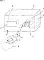
In
Das Fördermittel
Das Fördermittel
Die Steuereinrichtung
Entsteht nun während eines chirurgischen Eingriffs in dem Operationsfeld
Stellt die Steuereinrichtung
In diesem Zusammenhang ist es selbstverständlich ebenso vorgesehen, dass das Fördermittel
Sinkt die von dem Rauchgaspartikeldetektor
Die zuvor genannte Steuerung und/oder Regelung erfolgt gemäß weiterer Ausführungsbeispiele nicht nur anhand der Rauchgaspartikelkonzentration, sondern beispielsweise anhand der Rauchgaspartikelgröße. Ebenso ist vorgesehen, die Rauchgaspartikelkonzentration und die Rauchgaspartikelgröße zu berücksichtigen.The aforementioned control and / or regulation takes place according to further embodiments not only on the basis of the flue gas particle concentration, but for example on the basis of the flue gas particle size. It is also provided to take into account the flue gas particle concentration and the flue gas particle size.
Im Ergebnis wird die Rauchgasabsaugvorrichtung
Die medizinischen Rauchgase bzw. die Rauchgaspartikel
Anders als bei herkömmlichen Verfahren, bei denen die Filtersättigung lediglich anhand der Betriebsdauer der Rauchgasabsaugvorrichtung
Die Kapazität des Rauchgasfilters
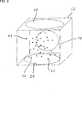
Die Rauchgasabsaugvorrichtung
Der Rauchgaspartikeldetektor
Das oben erläuterte System bietet den Vorteil, dass über eine Messung der optischen Dichte eine statistische Auswertung der Partikelgröße erfolgen kann. Von der Mehrzahl der Rauchgasfilter, die die Rauchgasabsaugvorrichtung
Bei einem Verfahren zum Betreiben der medizinischen Rauchgasabsaugvorrichtung
Alle genannten Merkmale, auch die den Zeichnungen allein zu entnehmenden sowie auch einzelne Merkmale, die in Kombination mit anderen Merkmalen offenbart sind, werden allein und in Kombination als erfindungswesentlich angesehen. Erfindungsgemäße Ausführungsformen können durch einzelne Merkmale oder eine Kombination mehrerer Merkmale erfüllt sein. Im Rahmen der Erfindung sind Merkmale, die mit „insbesondere“ oder „vorzugsweise“ gekennzeichnet sind, als fakultative Merkmale zu verstehen.All mentioned features, including the drawings alone to be taken as well as individual features that are disclosed in combination with other features are considered alone and in combination as essential to the invention. Embodiments of the invention may be accomplished by individual features or a combination of several features. In the context of the invention, features which are identified by "particular" or "preferably" are to be understood as optional features.
BezugszeichenlisteLIST OF REFERENCE NUMBERS
- 22
- Rauchgasabsaugvorrichtung Rauchgasabsaugvorrichtung
- 44
- Fördermittel funding
- 66
- Rauchgasfilter Flue gas filter
- 88th
- Steuereinrichtung control device
- 1010
- Frontplatte front panel
- 1212
- Bedienteil control panel
- 1414
- Rauchgaszufuhrkanal Flue gas supply channel
- 1616
- Rauchgaspartikeldetektor Smoke particle detector
- 1818
- Operationsfeld surgical field
- 2020
- Rauchgaspartikel Flue gas particles
- 2222
- Messkammer measuring chamber
- 2424
- optischer Emitter optical emitter
- 2626
- optischer Empfänger optical receiver
Claims (12)
Translated fromGermanPriority Applications (1)
| Application Number | Priority Date | Filing Date | Title |
|---|---|---|---|
| DE102016207666.3ADE102016207666B4 (en) | 2016-05-03 | 2016-05-03 | Medical smoke evacuation apparatus and method of operating the same |
Applications Claiming Priority (1)
| Application Number | Priority Date | Filing Date | Title |
|---|---|---|---|
| DE102016207666.3ADE102016207666B4 (en) | 2016-05-03 | 2016-05-03 | Medical smoke evacuation apparatus and method of operating the same |
Publications (2)
| Publication Number | Publication Date |
|---|---|
| DE102016207666A1true DE102016207666A1 (en) | 2017-11-09 |
| DE102016207666B4 DE102016207666B4 (en) | 2023-03-02 |
Family
ID=60119523
Family Applications (1)
| Application Number | Title | Priority Date | Filing Date |
|---|---|---|---|
| DE102016207666.3AActiveDE102016207666B4 (en) | 2016-05-03 | 2016-05-03 | Medical smoke evacuation apparatus and method of operating the same |
Country Status (1)
| Country | Link |
|---|---|
| DE (1) | DE102016207666B4 (en) |
Cited By (135)
| Publication number | Priority date | Publication date | Assignee | Title |
|---|---|---|---|---|
| EP3506303A1 (en)* | 2017-12-28 | 2019-07-03 | Ethicon LLC | Surgical evacuation sensing and motor control |
| EP3505198A1 (en)* | 2017-12-28 | 2019-07-03 | Ethicon LLC | Dual in-series large and small droplet filters |
| WO2019130125A1 (en)* | 2017-12-28 | 2019-07-04 | Ethicon Llc | Dual in-series large and small droplet filters |
| WO2019130117A1 (en)* | 2017-12-28 | 2019-07-04 | Ethicon Llc | Surgical evacuation sensing and motor control |
| EP3545887A1 (en)* | 2018-03-28 | 2019-10-02 | Ethicon LLC | Method for smoke evacuation for surgical hub |
| WO2019186502A1 (en)* | 2018-03-30 | 2019-10-03 | Ethicon Llc | Method for smoke evacuation for surgical hub |
| US10595887B2 (en) | 2017-12-28 | 2020-03-24 | Ethicon Llc | Systems for adjusting end effector parameters based on perioperative information |
| US10695081B2 (en) | 2017-12-28 | 2020-06-30 | Ethicon Llc | Controlling a surgical instrument according to sensed closure parameters |
| US10755813B2 (en) | 2017-12-28 | 2020-08-25 | Ethicon Llc | Communication of smoke evacuation system parameters to hub or cloud in smoke evacuation module for interactive surgical platform |
| US10758310B2 (en) | 2017-12-28 | 2020-09-01 | Ethicon Llc | Wireless pairing of a surgical device with another device within a sterile surgical field based on the usage and situational awareness of devices |
| US10772651B2 (en) | 2017-10-30 | 2020-09-15 | Ethicon Llc | Surgical instruments comprising a system for articulation and rotation compensation |
| US10849697B2 (en) | 2017-12-28 | 2020-12-01 | Ethicon Llc | Cloud interface for coupled surgical devices |
| US10892995B2 (en) | 2017-12-28 | 2021-01-12 | Ethicon Llc | Surgical network determination of prioritization of communication, interaction, or processing based on system or device needs |
| US10892899B2 (en) | 2017-12-28 | 2021-01-12 | Ethicon Llc | Self describing data packets generated at an issuing instrument |
| US10932872B2 (en) | 2017-12-28 | 2021-03-02 | Ethicon Llc | Cloud-based medical analytics for linking of local usage trends with the resource acquisition behaviors of larger data set |
| US10943454B2 (en) | 2017-12-28 | 2021-03-09 | Ethicon Llc | Detection and escalation of security responses of surgical instruments to increasing severity threats |
| US10944728B2 (en) | 2017-12-28 | 2021-03-09 | Ethicon Llc | Interactive surgical systems with encrypted communication capabilities |
| US10966791B2 (en) | 2017-12-28 | 2021-04-06 | Ethicon Llc | Cloud-based medical analytics for medical facility segmented individualization of instrument function |
| US10973520B2 (en) | 2018-03-28 | 2021-04-13 | Ethicon Llc | Surgical staple cartridge with firing member driven camming assembly that has an onboard tissue cutting feature |
| US10987178B2 (en) | 2017-12-28 | 2021-04-27 | Ethicon Llc | Surgical hub control arrangements |
| US11013563B2 (en) | 2017-12-28 | 2021-05-25 | Ethicon Llc | Drive arrangements for robot-assisted surgical platforms |
| US11026751B2 (en) | 2017-12-28 | 2021-06-08 | Cilag Gmbh International | Display of alignment of staple cartridge to prior linear staple line |
| US11026687B2 (en) | 2017-10-30 | 2021-06-08 | Cilag Gmbh International | Clip applier comprising clip advancing systems |
| US11051876B2 (en) | 2017-12-28 | 2021-07-06 | Cilag Gmbh International | Surgical evacuation flow paths |
| US11056244B2 (en) | 2017-12-28 | 2021-07-06 | Cilag Gmbh International | Automated data scaling, alignment, and organizing based on predefined parameters within surgical networks |
| US11058498B2 (en) | 2017-12-28 | 2021-07-13 | Cilag Gmbh International | Cooperative surgical actions for robot-assisted surgical platforms |
| US11069012B2 (en) | 2017-12-28 | 2021-07-20 | Cilag Gmbh International | Interactive surgical systems with condition handling of devices and data capabilities |
| US11076921B2 (en) | 2017-12-28 | 2021-08-03 | Cilag Gmbh International | Adaptive control program updates for surgical hubs |
| US11090047B2 (en) | 2018-03-28 | 2021-08-17 | Cilag Gmbh International | Surgical instrument comprising an adaptive control system |
| US11096693B2 (en) | 2017-12-28 | 2021-08-24 | Cilag Gmbh International | Adjustment of staple height of at least one row of staples based on the sensed tissue thickness or force in closing |
| US11100631B2 (en) | 2017-12-28 | 2021-08-24 | Cilag Gmbh International | Use of laser light and red-green-blue coloration to determine properties of back scattered light |
| US11096688B2 (en) | 2018-03-28 | 2021-08-24 | Cilag Gmbh International | Rotary driven firing members with different anvil and channel engagement features |
| US11114195B2 (en) | 2017-12-28 | 2021-09-07 | Cilag Gmbh International | Surgical instrument with a tissue marking assembly |
| US11109866B2 (en) | 2017-12-28 | 2021-09-07 | Cilag Gmbh International | Method for circular stapler control algorithm adjustment based on situational awareness |
| US11129611B2 (en) | 2018-03-28 | 2021-09-28 | Cilag Gmbh International | Surgical staplers with arrangements for maintaining a firing member thereof in a locked configuration unless a compatible cartridge has been installed therein |
| US11132462B2 (en) | 2017-12-28 | 2021-09-28 | Cilag Gmbh International | Data stripping method to interrogate patient records and create anonymized record |
| US11147607B2 (en) | 2017-12-28 | 2021-10-19 | Cilag Gmbh International | Bipolar combination device that automatically adjusts pressure based on energy modality |
| US11166772B2 (en) | 2017-12-28 | 2021-11-09 | Cilag Gmbh International | Surgical hub coordination of control and communication of operating room devices |
| US11179208B2 (en) | 2017-12-28 | 2021-11-23 | Cilag Gmbh International | Cloud-based medical analytics for security and authentication trends and reactive measures |
| US11179175B2 (en) | 2017-12-28 | 2021-11-23 | Cilag Gmbh International | Controlling an ultrasonic surgical instrument according to tissue location |
| US11202570B2 (en) | 2017-12-28 | 2021-12-21 | Cilag Gmbh International | Communication hub and storage device for storing parameters and status of a surgical device to be shared with cloud based analytics systems |
| US11207067B2 (en) | 2018-03-28 | 2021-12-28 | Cilag Gmbh International | Surgical stapling device with separate rotary driven closure and firing systems and firing member that engages both jaws while firing |
| US11219453B2 (en) | 2018-03-28 | 2022-01-11 | Cilag Gmbh International | Surgical stapling devices with cartridge compatible closure and firing lockout arrangements |
| US11229436B2 (en) | 2017-10-30 | 2022-01-25 | Cilag Gmbh International | Surgical system comprising a surgical tool and a surgical hub |
| US11234756B2 (en) | 2017-12-28 | 2022-02-01 | Cilag Gmbh International | Powered surgical tool with predefined adjustable control algorithm for controlling end effector parameter |
| US11253315B2 (en) | 2017-12-28 | 2022-02-22 | Cilag Gmbh International | Increasing radio frequency to create pad-less monopolar loop |
| US11257589B2 (en) | 2017-12-28 | 2022-02-22 | Cilag Gmbh International | Real-time analysis of comprehensive cost of all instrumentation used in surgery utilizing data fluidity to track instruments through stocking and in-house processes |
| US11259806B2 (en) | 2018-03-28 | 2022-03-01 | Cilag Gmbh International | Surgical stapling devices with features for blocking advancement of a camming assembly of an incompatible cartridge installed therein |
| US11259807B2 (en) | 2019-02-19 | 2022-03-01 | Cilag Gmbh International | Staple cartridges with cam surfaces configured to engage primary and secondary portions of a lockout of a surgical stapling device |
| US11259830B2 (en) | 2018-03-08 | 2022-03-01 | Cilag Gmbh International | Methods for controlling temperature in ultrasonic device |
| WO2022043580A1 (en)* | 2020-08-31 | 2022-03-03 | Smices | Device for filtering surgical smoke |
| US11266468B2 (en) | 2017-12-28 | 2022-03-08 | Cilag Gmbh International | Cooperative utilization of data derived from secondary sources by intelligent surgical hubs |
| US11273001B2 (en) | 2017-12-28 | 2022-03-15 | Cilag Gmbh International | Surgical hub and modular device response adjustment based on situational awareness |
| US11278280B2 (en) | 2018-03-28 | 2022-03-22 | Cilag Gmbh International | Surgical instrument comprising a jaw closure lockout |
| US11278281B2 (en) | 2017-12-28 | 2022-03-22 | Cilag Gmbh International | Interactive surgical system |
| US11284936B2 (en) | 2017-12-28 | 2022-03-29 | Cilag Gmbh International | Surgical instrument having a flexible electrode |
| US11291510B2 (en) | 2017-10-30 | 2022-04-05 | Cilag Gmbh International | Method of hub communication with surgical instrument systems |
| US11291495B2 (en) | 2017-12-28 | 2022-04-05 | Cilag Gmbh International | Interruption of energy due to inadvertent capacitive coupling |
| US11298148B2 (en) | 2018-03-08 | 2022-04-12 | Cilag Gmbh International | Live time tissue classification using electrical parameters |
| US11308075B2 (en) | 2017-12-28 | 2022-04-19 | Cilag Gmbh International | Surgical network, instrument, and cloud responses based on validation of received dataset and authentication of its source and integrity |
| US11304720B2 (en) | 2017-12-28 | 2022-04-19 | Cilag Gmbh International | Activation of energy devices |
| US11304745B2 (en) | 2017-12-28 | 2022-04-19 | Cilag Gmbh International | Surgical evacuation sensing and display |
| US11304763B2 (en) | 2017-12-28 | 2022-04-19 | Cilag Gmbh International | Image capturing of the areas outside the abdomen to improve placement and control of a surgical device in use |
| US11304699B2 (en) | 2017-12-28 | 2022-04-19 | Cilag Gmbh International | Method for adaptive control schemes for surgical network control and interaction |
| US11311306B2 (en) | 2017-12-28 | 2022-04-26 | Cilag Gmbh International | Surgical systems for detecting end effector tissue distribution irregularities |
| US11311342B2 (en) | 2017-10-30 | 2022-04-26 | Cilag Gmbh International | Method for communicating with surgical instrument systems |
| US11317915B2 (en) | 2019-02-19 | 2022-05-03 | Cilag Gmbh International | Universal cartridge based key feature that unlocks multiple lockout arrangements in different surgical staplers |
| US11317937B2 (en) | 2018-03-08 | 2022-05-03 | Cilag Gmbh International | Determining the state of an ultrasonic end effector |
| USD950728S1 (en) | 2019-06-25 | 2022-05-03 | Cilag Gmbh International | Surgical staple cartridge |
| US11317919B2 (en) | 2017-10-30 | 2022-05-03 | Cilag Gmbh International | Clip applier comprising a clip crimping system |
| US11324557B2 (en) | 2017-12-28 | 2022-05-10 | Cilag Gmbh International | Surgical instrument with a sensing array |
| USD952144S1 (en) | 2019-06-25 | 2022-05-17 | Cilag Gmbh International | Surgical staple cartridge retainer with firing system authentication key |
| US11337746B2 (en) | 2018-03-08 | 2022-05-24 | Cilag Gmbh International | Smart blade and power pulsing |
| US11357503B2 (en) | 2019-02-19 | 2022-06-14 | Cilag Gmbh International | Staple cartridge retainers with frangible retention features and methods of using same |
| US11364075B2 (en) | 2017-12-28 | 2022-06-21 | Cilag Gmbh International | Radio frequency energy device for delivering combined electrical signals |
| US11369377B2 (en) | 2019-02-19 | 2022-06-28 | Cilag Gmbh International | Surgical stapling assembly with cartridge based retainer configured to unlock a firing lockout |
| US11376002B2 (en) | 2017-12-28 | 2022-07-05 | Cilag Gmbh International | Surgical instrument cartridge sensor assemblies |
| US11389164B2 (en) | 2017-12-28 | 2022-07-19 | Cilag Gmbh International | Method of using reinforced flexible circuits with multiple sensors to optimize performance of radio frequency devices |
| US11410259B2 (en) | 2017-12-28 | 2022-08-09 | Cilag Gmbh International | Adaptive control program updates for surgical devices |
| US11423007B2 (en) | 2017-12-28 | 2022-08-23 | Cilag Gmbh International | Adjustment of device control programs based on stratified contextual data in addition to the data |
| US11419630B2 (en) | 2017-12-28 | 2022-08-23 | Cilag Gmbh International | Surgical system distributed processing |
| US11419667B2 (en) | 2017-12-28 | 2022-08-23 | Cilag Gmbh International | Ultrasonic energy device which varies pressure applied by clamp arm to provide threshold control pressure at a cut progression location |
| US11424027B2 (en) | 2017-12-28 | 2022-08-23 | Cilag Gmbh International | Method for operating surgical instrument systems |
| US11432885B2 (en) | 2017-12-28 | 2022-09-06 | Cilag Gmbh International | Sensing arrangements for robot-assisted surgical platforms |
| US11446052B2 (en) | 2017-12-28 | 2022-09-20 | Cilag Gmbh International | Variation of radio frequency and ultrasonic power level in cooperation with varying clamp arm pressure to achieve predefined heat flux or power applied to tissue |
| USD964564S1 (en) | 2019-06-25 | 2022-09-20 | Cilag Gmbh International | Surgical staple cartridge retainer with a closure system authentication key |
| US11464535B2 (en) | 2017-12-28 | 2022-10-11 | Cilag Gmbh International | Detection of end effector emersion in liquid |
| US11464511B2 (en) | 2019-02-19 | 2022-10-11 | Cilag Gmbh International | Surgical staple cartridges with movable authentication key arrangements |
| US11464559B2 (en) | 2017-12-28 | 2022-10-11 | Cilag Gmbh International | Estimating state of ultrasonic end effector and control system therefor |
| US11471156B2 (en) | 2018-03-28 | 2022-10-18 | Cilag Gmbh International | Surgical stapling devices with improved rotary driven closure systems |
| US11504192B2 (en) | 2014-10-30 | 2022-11-22 | Cilag Gmbh International | Method of hub communication with surgical instrument systems |
| US11510741B2 (en) | 2017-10-30 | 2022-11-29 | Cilag Gmbh International | Method for producing a surgical instrument comprising a smart electrical system |
| US11529187B2 (en) | 2017-12-28 | 2022-12-20 | Cilag Gmbh International | Surgical evacuation sensor arrangements |
| US11540855B2 (en) | 2017-12-28 | 2023-01-03 | Cilag Gmbh International | Controlling activation of an ultrasonic surgical instrument according to the presence of tissue |
| US11559307B2 (en) | 2017-12-28 | 2023-01-24 | Cilag Gmbh International | Method of robotic hub communication, detection, and control |
| US11559308B2 (en) | 2017-12-28 | 2023-01-24 | Cilag Gmbh International | Method for smart energy device infrastructure |
| US11564756B2 (en) | 2017-10-30 | 2023-01-31 | Cilag Gmbh International | Method of hub communication with surgical instrument systems |
| US11571234B2 (en) | 2017-12-28 | 2023-02-07 | Cilag Gmbh International | Temperature control of ultrasonic end effector and control system therefor |
| US11576677B2 (en) | 2017-12-28 | 2023-02-14 | Cilag Gmbh International | Method of hub communication, processing, display, and cloud analytics |
| US11589888B2 (en) | 2017-12-28 | 2023-02-28 | Cilag Gmbh International | Method for controlling smart energy devices |
| US11589932B2 (en) | 2017-12-28 | 2023-02-28 | Cilag Gmbh International | Usage and technique analysis of surgeon / staff performance against a baseline to optimize device utilization and performance for both current and future procedures |
| US11596291B2 (en) | 2017-12-28 | 2023-03-07 | Cilag Gmbh International | Method of compressing tissue within a stapling device and simultaneously displaying of the location of the tissue within the jaws |
| US11602393B2 (en) | 2017-12-28 | 2023-03-14 | Cilag Gmbh International | Surgical evacuation sensing and generator control |
| US11612444B2 (en) | 2017-12-28 | 2023-03-28 | Cilag Gmbh International | Adjustment of a surgical device function based on situational awareness |
| US11659023B2 (en) | 2017-12-28 | 2023-05-23 | Cilag Gmbh International | Method of hub communication |
| US11666331B2 (en) | 2017-12-28 | 2023-06-06 | Cilag Gmbh International | Systems for detecting proximity of surgical end effector to cancerous tissue |
| US11744604B2 (en) | 2017-12-28 | 2023-09-05 | Cilag Gmbh International | Surgical instrument with a hardware-only control circuit |
| US11771487B2 (en) | 2017-12-28 | 2023-10-03 | Cilag Gmbh International | Mechanisms for controlling different electromechanical systems of an electrosurgical instrument |
| US11786245B2 (en) | 2017-12-28 | 2023-10-17 | Cilag Gmbh International | Surgical systems with prioritized data transmission capabilities |
| US11786251B2 (en) | 2017-12-28 | 2023-10-17 | Cilag Gmbh International | Method for adaptive control schemes for surgical network control and interaction |
| US11801098B2 (en) | 2017-10-30 | 2023-10-31 | Cilag Gmbh International | Method of hub communication with surgical instrument systems |
| US11818052B2 (en) | 2017-12-28 | 2023-11-14 | Cilag Gmbh International | Surgical network determination of prioritization of communication, interaction, or processing based on system or device needs |
| US11832840B2 (en) | 2017-12-28 | 2023-12-05 | Cilag Gmbh International | Surgical instrument having a flexible circuit |
| US11832899B2 (en) | 2017-12-28 | 2023-12-05 | Cilag Gmbh International | Surgical systems with autonomously adjustable control programs |
| US11857152B2 (en) | 2017-12-28 | 2024-01-02 | Cilag Gmbh International | Surgical hub spatial awareness to determine devices in operating theater |
| US11864728B2 (en) | 2017-12-28 | 2024-01-09 | Cilag Gmbh International | Characterization of tissue irregularities through the use of mono-chromatic light refractivity |
| US11871901B2 (en) | 2012-05-20 | 2024-01-16 | Cilag Gmbh International | Method for situational awareness for surgical network or surgical network connected device capable of adjusting function based on a sensed situation or usage |
| US11896443B2 (en) | 2017-12-28 | 2024-02-13 | Cilag Gmbh International | Control of a surgical system through a surgical barrier |
| US11896322B2 (en) | 2017-12-28 | 2024-02-13 | Cilag Gmbh International | Sensing the patient position and contact utilizing the mono-polar return pad electrode to provide situational awareness to the hub |
| US11903601B2 (en) | 2017-12-28 | 2024-02-20 | Cilag Gmbh International | Surgical instrument comprising a plurality of drive systems |
| US11911045B2 (en) | 2017-10-30 | 2024-02-27 | Cllag GmbH International | Method for operating a powered articulating multi-clip applier |
| US11937769B2 (en) | 2017-12-28 | 2024-03-26 | Cilag Gmbh International | Method of hub communication, processing, storage and display |
| US11969216B2 (en) | 2017-12-28 | 2024-04-30 | Cilag Gmbh International | Surgical network recommendations from real time analysis of procedure variables against a baseline highlighting differences from the optimal solution |
| US11998193B2 (en) | 2017-12-28 | 2024-06-04 | Cilag Gmbh International | Method for usage of the shroud as an aspect of sensing or controlling a powered surgical device, and a control algorithm to adjust its default operation |
| US12029506B2 (en) | 2017-12-28 | 2024-07-09 | Cilag Gmbh International | Method of cloud based data analytics for use with the hub |
| US12035890B2 (en) | 2017-12-28 | 2024-07-16 | Cilag Gmbh International | Method of sensing particulate from smoke evacuated from a patient, adjusting the pump speed based on the sensed information, and communicating the functional parameters of the system to the hub |
| US12062442B2 (en) | 2017-12-28 | 2024-08-13 | Cilag Gmbh International | Method for operating surgical instrument systems |
| US12127729B2 (en) | 2017-12-28 | 2024-10-29 | Cilag Gmbh International | Method for smoke evacuation for surgical hub |
| US12133773B2 (en) | 2017-12-28 | 2024-11-05 | Cilag Gmbh International | Surgical hub and modular device response adjustment based on situational awareness |
| US12226151B2 (en) | 2017-12-28 | 2025-02-18 | Cilag Gmbh International | Capacitive coupled return path pad with separable array elements |
| US12303159B2 (en) | 2018-03-08 | 2025-05-20 | Cilag Gmbh International | Methods for estimating and controlling state of ultrasonic end effector |
| US12318152B2 (en) | 2017-12-28 | 2025-06-03 | Cilag Gmbh International | Computer implemented interactive surgical systems |
| US12376855B2 (en) | 2017-12-28 | 2025-08-05 | Cilag Gmbh International | Safety systems for smart powered surgical stapling |
| US12396806B2 (en) | 2017-12-28 | 2025-08-26 | Cilag Gmbh International | Adjustment of a surgical device function based on situational awareness |
| US12433508B2 (en) | 2017-12-28 | 2025-10-07 | Cilag Gmbh International | Surgical system having a surgical instrument controlled based on comparison of sensor and database data |
Citations (2)
| Publication number | Priority date | Publication date | Assignee | Title |
|---|---|---|---|---|
| US5242474A (en)* | 1991-11-01 | 1993-09-07 | Sorenson Laboratories, Inc. | Dual mode laser smoke evacuation system with sequential filter monitor and vacuum compensation |
| DE102008035770A1 (en)* | 2008-07-31 | 2010-02-18 | Eads Deutschland Gmbh | Optical particle detector and detection method |
- 2016
- 2016-05-03DEDE102016207666.3Apatent/DE102016207666B4/enactiveActive
Patent Citations (2)
| Publication number | Priority date | Publication date | Assignee | Title |
|---|---|---|---|---|
| US5242474A (en)* | 1991-11-01 | 1993-09-07 | Sorenson Laboratories, Inc. | Dual mode laser smoke evacuation system with sequential filter monitor and vacuum compensation |
| DE102008035770A1 (en)* | 2008-07-31 | 2010-02-18 | Eads Deutschland Gmbh | Optical particle detector and detection method |
Cited By (253)
| Publication number | Priority date | Publication date | Assignee | Title |
|---|---|---|---|---|
| US11871901B2 (en) | 2012-05-20 | 2024-01-16 | Cilag Gmbh International | Method for situational awareness for surgical network or surgical network connected device capable of adjusting function based on a sensed situation or usage |
| US11504192B2 (en) | 2014-10-30 | 2022-11-22 | Cilag Gmbh International | Method of hub communication with surgical instrument systems |
| US11793537B2 (en) | 2017-10-30 | 2023-10-24 | Cilag Gmbh International | Surgical instrument comprising an adaptive electrical system |
| US10932806B2 (en) | 2017-10-30 | 2021-03-02 | Ethicon Llc | Reactive algorithm for surgical system |
| US12035983B2 (en) | 2017-10-30 | 2024-07-16 | Cilag Gmbh International | Method for producing a surgical instrument comprising a smart electrical system |
| US11925373B2 (en) | 2017-10-30 | 2024-03-12 | Cilag Gmbh International | Surgical suturing instrument comprising a non-circular needle |
| US11911045B2 (en) | 2017-10-30 | 2024-02-27 | Cllag GmbH International | Method for operating a powered articulating multi-clip applier |
| US12121255B2 (en) | 2017-10-30 | 2024-10-22 | Cilag Gmbh International | Electrical power output control based on mechanical forces |
| US11819231B2 (en) | 2017-10-30 | 2023-11-21 | Cilag Gmbh International | Adaptive control programs for a surgical system comprising more than one type of cartridge |
| US11801098B2 (en) | 2017-10-30 | 2023-10-31 | Cilag Gmbh International | Method of hub communication with surgical instrument systems |
| US11103268B2 (en) | 2017-10-30 | 2021-08-31 | Cilag Gmbh International | Surgical clip applier comprising adaptive firing control |
| US11759224B2 (en) | 2017-10-30 | 2023-09-19 | Cilag Gmbh International | Surgical instrument systems comprising handle arrangements |
| US10772651B2 (en) | 2017-10-30 | 2020-09-15 | Ethicon Llc | Surgical instruments comprising a system for articulation and rotation compensation |
| US11696778B2 (en) | 2017-10-30 | 2023-07-11 | Cilag Gmbh International | Surgical dissectors configured to apply mechanical and electrical energy |
| US11648022B2 (en) | 2017-10-30 | 2023-05-16 | Cilag Gmbh International | Surgical instrument systems comprising battery arrangements |
| US11602366B2 (en) | 2017-10-30 | 2023-03-14 | Cilag Gmbh International | Surgical suturing instrument configured to manipulate tissue using mechanical and electrical power |
| US11564703B2 (en) | 2017-10-30 | 2023-01-31 | Cilag Gmbh International | Surgical suturing instrument comprising a capture width which is larger than trocar diameter |
| US11564756B2 (en) | 2017-10-30 | 2023-01-31 | Cilag Gmbh International | Method of hub communication with surgical instrument systems |
| US10959744B2 (en) | 2017-10-30 | 2021-03-30 | Ethicon Llc | Surgical dissectors and manufacturing techniques |
| US11510741B2 (en) | 2017-10-30 | 2022-11-29 | Cilag Gmbh International | Method for producing a surgical instrument comprising a smart electrical system |
| US12059218B2 (en) | 2017-10-30 | 2024-08-13 | Cilag Gmbh International | Method of hub communication with surgical instrument systems |
| US12329467B2 (en) | 2017-10-30 | 2025-06-17 | Cilag Gmbh International | Method of hub communication with surgical instrument systems |
| US11317919B2 (en) | 2017-10-30 | 2022-05-03 | Cilag Gmbh International | Clip applier comprising a clip crimping system |
| US11406390B2 (en) | 2017-10-30 | 2022-08-09 | Cilag Gmbh International | Clip applier comprising interchangeable clip reloads |
| US10980560B2 (en) | 2017-10-30 | 2021-04-20 | Ethicon Llc | Surgical instrument systems comprising feedback mechanisms |
| US11413042B2 (en) | 2017-10-30 | 2022-08-16 | Cilag Gmbh International | Clip applier comprising a reciprocating clip advancing member |
| US11311342B2 (en) | 2017-10-30 | 2022-04-26 | Cilag Gmbh International | Method for communicating with surgical instrument systems |
| US11026712B2 (en) | 2017-10-30 | 2021-06-08 | Cilag Gmbh International | Surgical instruments comprising a shifting mechanism |
| US11291510B2 (en) | 2017-10-30 | 2022-04-05 | Cilag Gmbh International | Method of hub communication with surgical instrument systems |
| US11026713B2 (en) | 2017-10-30 | 2021-06-08 | Cilag Gmbh International | Surgical clip applier configured to store clips in a stored state |
| US11026687B2 (en) | 2017-10-30 | 2021-06-08 | Cilag Gmbh International | Clip applier comprising clip advancing systems |
| US11045197B2 (en) | 2017-10-30 | 2021-06-29 | Cilag Gmbh International | Clip applier comprising a movable clip magazine |
| US11291465B2 (en) | 2017-10-30 | 2022-04-05 | Cilag Gmbh International | Surgical instruments comprising a lockable end effector socket |
| US11229436B2 (en) | 2017-10-30 | 2022-01-25 | Cilag Gmbh International | Surgical system comprising a surgical tool and a surgical hub |
| US11207090B2 (en) | 2017-10-30 | 2021-12-28 | Cilag Gmbh International | Surgical instruments comprising a biased shifting mechanism |
| US11051836B2 (en) | 2017-10-30 | 2021-07-06 | Cilag Gmbh International | Surgical clip applier comprising an empty clip cartridge lockout |
| US11141160B2 (en) | 2017-10-30 | 2021-10-12 | Cilag Gmbh International | Clip applier comprising a motor controller |
| US11129636B2 (en) | 2017-10-30 | 2021-09-28 | Cilag Gmbh International | Surgical instruments comprising an articulation drive that provides for high articulation angles |
| US11071560B2 (en) | 2017-10-30 | 2021-07-27 | Cilag Gmbh International | Surgical clip applier comprising adaptive control in response to a strain gauge circuit |
| US11123070B2 (en) | 2017-10-30 | 2021-09-21 | Cilag Gmbh International | Clip applier comprising a rotatable clip magazine |
| US11109878B2 (en) | 2017-10-30 | 2021-09-07 | Cilag Gmbh International | Surgical clip applier comprising an automatic clip feeding system |
| US11857152B2 (en) | 2017-12-28 | 2024-01-02 | Cilag Gmbh International | Surgical hub spatial awareness to determine devices in operating theater |
| US11589932B2 (en) | 2017-12-28 | 2023-02-28 | Cilag Gmbh International | Usage and technique analysis of surgeon / staff performance against a baseline to optimize device utilization and performance for both current and future procedures |
| US11100631B2 (en) | 2017-12-28 | 2021-08-24 | Cilag Gmbh International | Use of laser light and red-green-blue coloration to determine properties of back scattered light |
| US12433508B2 (en) | 2017-12-28 | 2025-10-07 | Cilag Gmbh International | Surgical system having a surgical instrument controlled based on comparison of sensor and database data |
| US12396806B2 (en) | 2017-12-28 | 2025-08-26 | Cilag Gmbh International | Adjustment of a surgical device function based on situational awareness |
| US11114195B2 (en) | 2017-12-28 | 2021-09-07 | Cilag Gmbh International | Surgical instrument with a tissue marking assembly |
| US11109866B2 (en) | 2017-12-28 | 2021-09-07 | Cilag Gmbh International | Method for circular stapler control algorithm adjustment based on situational awareness |
| US12383115B2 (en) | 2017-12-28 | 2025-08-12 | Cilag Gmbh International | Method for smart energy device infrastructure |
| US11076921B2 (en) | 2017-12-28 | 2021-08-03 | Cilag Gmbh International | Adaptive control program updates for surgical hubs |
| US12376855B2 (en) | 2017-12-28 | 2025-08-05 | Cilag Gmbh International | Safety systems for smart powered surgical stapling |
| US11069012B2 (en) | 2017-12-28 | 2021-07-20 | Cilag Gmbh International | Interactive surgical systems with condition handling of devices and data capabilities |
| US11132462B2 (en) | 2017-12-28 | 2021-09-28 | Cilag Gmbh International | Data stripping method to interrogate patient records and create anonymized record |
| US11058498B2 (en) | 2017-12-28 | 2021-07-13 | Cilag Gmbh International | Cooperative surgical actions for robot-assisted surgical platforms |
| US11147607B2 (en) | 2017-12-28 | 2021-10-19 | Cilag Gmbh International | Bipolar combination device that automatically adjusts pressure based on energy modality |
| US11160605B2 (en) | 2017-12-28 | 2021-11-02 | Cilag Gmbh International | Surgical evacuation sensing and motor control |
| EP3505198A1 (en)* | 2017-12-28 | 2019-07-03 | Ethicon LLC | Dual in-series large and small droplet filters |
| US11166772B2 (en) | 2017-12-28 | 2021-11-09 | Cilag Gmbh International | Surgical hub coordination of control and communication of operating room devices |
| US11179208B2 (en) | 2017-12-28 | 2021-11-23 | Cilag Gmbh International | Cloud-based medical analytics for security and authentication trends and reactive measures |
| US11179204B2 (en) | 2017-12-28 | 2021-11-23 | Cilag Gmbh International | Wireless pairing of a surgical device with another device within a sterile surgical field based on the usage and situational awareness of devices |
| US11179175B2 (en) | 2017-12-28 | 2021-11-23 | Cilag Gmbh International | Controlling an ultrasonic surgical instrument according to tissue location |
| US12318152B2 (en) | 2017-12-28 | 2025-06-03 | Cilag Gmbh International | Computer implemented interactive surgical systems |
| US11202570B2 (en) | 2017-12-28 | 2021-12-21 | Cilag Gmbh International | Communication hub and storage device for storing parameters and status of a surgical device to be shared with cloud based analytics systems |
| US11056244B2 (en) | 2017-12-28 | 2021-07-06 | Cilag Gmbh International | Automated data scaling, alignment, and organizing based on predefined parameters within surgical networks |
| US12310586B2 (en) | 2017-12-28 | 2025-05-27 | Cilag Gmbh International | Method for adaptive control schemes for surgical network control and interaction |
| US11213359B2 (en) | 2017-12-28 | 2022-01-04 | Cilag Gmbh International | Controllers for robot-assisted surgical platforms |
| US12295674B2 (en) | 2017-12-28 | 2025-05-13 | Cilag Gmbh International | Usage and technique analysis of surgeon / staff performance against a baseline to optimize device utilization and performance for both current and future procedures |
| US12256995B2 (en) | 2017-12-28 | 2025-03-25 | Cilag Gmbh International | Surgical network recommendations from real time analysis of procedure variables against a baseline highlighting differences from the optimal solution |
| US11051876B2 (en) | 2017-12-28 | 2021-07-06 | Cilag Gmbh International | Surgical evacuation flow paths |
| US11234756B2 (en) | 2017-12-28 | 2022-02-01 | Cilag Gmbh International | Powered surgical tool with predefined adjustable control algorithm for controlling end effector parameter |
| US11253315B2 (en) | 2017-12-28 | 2022-02-22 | Cilag Gmbh International | Increasing radio frequency to create pad-less monopolar loop |
| US11257589B2 (en) | 2017-12-28 | 2022-02-22 | Cilag Gmbh International | Real-time analysis of comprehensive cost of all instrumentation used in surgery utilizing data fluidity to track instruments through stocking and in-house processes |
| US12239320B2 (en) | 2017-12-28 | 2025-03-04 | Cilag Gmbh International | Method of using reinforced flexible circuits with multiple sensors to optimize performance of radio frequency devices |
| US12232729B2 (en) | 2017-12-28 | 2025-02-25 | Cilag Gmbh International | Systems for detecting proximity of surgical end effector to cancerous tissue |
| US12226166B2 (en) | 2017-12-28 | 2025-02-18 | Cilag Gmbh International | Surgical instrument with a sensing array |
| US12226151B2 (en) | 2017-12-28 | 2025-02-18 | Cilag Gmbh International | Capacitive coupled return path pad with separable array elements |
| US12207817B2 (en) | 2017-12-28 | 2025-01-28 | Cilag Gmbh International | Safety systems for smart powered surgical stapling |
| US11266468B2 (en) | 2017-12-28 | 2022-03-08 | Cilag Gmbh International | Cooperative utilization of data derived from secondary sources by intelligent surgical hubs |
| US11273001B2 (en) | 2017-12-28 | 2022-03-15 | Cilag Gmbh International | Surgical hub and modular device response adjustment based on situational awareness |
| US12193636B2 (en) | 2017-12-28 | 2025-01-14 | Cilag Gmbh International | Characterization of tissue irregularities through the use of mono-chromatic light refractivity |
| US12193766B2 (en) | 2017-12-28 | 2025-01-14 | Cilag Gmbh International | Situationally aware surgical system configured for use during a surgical procedure |
| US11278281B2 (en) | 2017-12-28 | 2022-03-22 | Cilag Gmbh International | Interactive surgical system |
| US11284936B2 (en) | 2017-12-28 | 2022-03-29 | Cilag Gmbh International | Surgical instrument having a flexible electrode |
| US12144518B2 (en) | 2017-12-28 | 2024-11-19 | Cilag Gmbh International | Surgical systems for detecting end effector tissue distribution irregularities |
| US12137991B2 (en) | 2017-12-28 | 2024-11-12 | Cilag Gmbh International | Display arrangements for robot-assisted surgical platforms |
| US11045591B2 (en) | 2017-12-28 | 2021-06-29 | Cilag Gmbh International | Dual in-series large and small droplet filters |
| US11026751B2 (en) | 2017-12-28 | 2021-06-08 | Cilag Gmbh International | Display of alignment of staple cartridge to prior linear staple line |
| US11291495B2 (en) | 2017-12-28 | 2022-04-05 | Cilag Gmbh International | Interruption of energy due to inadvertent capacitive coupling |
| US12133773B2 (en) | 2017-12-28 | 2024-11-05 | Cilag Gmbh International | Surgical hub and modular device response adjustment based on situational awareness |
| US12133660B2 (en) | 2017-12-28 | 2024-11-05 | Cilag Gmbh International | Controlling a temperature of an ultrasonic electromechanical blade according to frequency |
| US12133709B2 (en) | 2017-12-28 | 2024-11-05 | Cilag Gmbh International | Communication hub and storage device for storing parameters and status of a surgical device to be shared with cloud based analytics systems |
| US11308075B2 (en) | 2017-12-28 | 2022-04-19 | Cilag Gmbh International | Surgical network, instrument, and cloud responses based on validation of received dataset and authentication of its source and integrity |
| US11304720B2 (en) | 2017-12-28 | 2022-04-19 | Cilag Gmbh International | Activation of energy devices |
| US11304745B2 (en) | 2017-12-28 | 2022-04-19 | Cilag Gmbh International | Surgical evacuation sensing and display |
| US11304763B2 (en) | 2017-12-28 | 2022-04-19 | Cilag Gmbh International | Image capturing of the areas outside the abdomen to improve placement and control of a surgical device in use |
| US11304699B2 (en) | 2017-12-28 | 2022-04-19 | Cilag Gmbh International | Method for adaptive control schemes for surgical network control and interaction |
| US11311306B2 (en) | 2017-12-28 | 2022-04-26 | Cilag Gmbh International | Surgical systems for detecting end effector tissue distribution irregularities |
| US11013563B2 (en) | 2017-12-28 | 2021-05-25 | Ethicon Llc | Drive arrangements for robot-assisted surgical platforms |
| US12127729B2 (en) | 2017-12-28 | 2024-10-29 | Cilag Gmbh International | Method for smoke evacuation for surgical hub |
| WO2019130125A1 (en)* | 2017-12-28 | 2019-07-04 | Ethicon Llc | Dual in-series large and small droplet filters |
| US12096985B2 (en) | 2017-12-28 | 2024-09-24 | Cilag Gmbh International | Surgical network recommendations from real time analysis of procedure variables against a baseline highlighting differences from the optimal solution |
| US10987178B2 (en) | 2017-12-28 | 2021-04-27 | Ethicon Llc | Surgical hub control arrangements |
| US11324557B2 (en) | 2017-12-28 | 2022-05-10 | Cilag Gmbh International | Surgical instrument with a sensing array |
| US12096916B2 (en) | 2017-12-28 | 2024-09-24 | Cilag Gmbh International | Method of sensing particulate from smoke evacuated from a patient, adjusting the pump speed based on the sensed information, and communicating the functional parameters of the system to the hub |
| US12076010B2 (en) | 2017-12-28 | 2024-09-03 | Cilag Gmbh International | Surgical instrument cartridge sensor assemblies |
| CN111566750B (en)* | 2017-12-28 | 2024-08-23 | 爱惜康有限责任公司 | Surgical drainage sensing and motor control |
| WO2019130117A1 (en)* | 2017-12-28 | 2019-07-04 | Ethicon Llc | Surgical evacuation sensing and motor control |
| US12059169B2 (en) | 2017-12-28 | 2024-08-13 | Cilag Gmbh International | Controlling an ultrasonic surgical instrument according to tissue location |
| US12059124B2 (en) | 2017-12-28 | 2024-08-13 | Cilag Gmbh International | Surgical hub spatial awareness to determine devices in operating theater |
| US11364075B2 (en) | 2017-12-28 | 2022-06-21 | Cilag Gmbh International | Radio frequency energy device for delivering combined electrical signals |
| US12062442B2 (en) | 2017-12-28 | 2024-08-13 | Cilag Gmbh International | Method for operating surgical instrument systems |
| US11376002B2 (en) | 2017-12-28 | 2022-07-05 | Cilag Gmbh International | Surgical instrument cartridge sensor assemblies |
| US11382697B2 (en) | 2017-12-28 | 2022-07-12 | Cilag Gmbh International | Surgical instruments comprising button circuits |
| US12053159B2 (en) | 2017-12-28 | 2024-08-06 | Cilag Gmbh International | Method of sensing particulate from smoke evacuated from a patient, adjusting the pump speed based on the sensed information, and communicating the functional parameters of the system to the hub |
| US11389164B2 (en) | 2017-12-28 | 2022-07-19 | Cilag Gmbh International | Method of using reinforced flexible circuits with multiple sensors to optimize performance of radio frequency devices |
| US12048496B2 (en) | 2017-12-28 | 2024-07-30 | Cilag Gmbh International | Adaptive control program updates for surgical hubs |
| US11410259B2 (en) | 2017-12-28 | 2022-08-09 | Cilag Gmbh International | Adaptive control program updates for surgical devices |
| US12042207B2 (en) | 2017-12-28 | 2024-07-23 | Cilag Gmbh International | Estimating state of ultrasonic end effector and control system therefor |
| US12035890B2 (en) | 2017-12-28 | 2024-07-16 | Cilag Gmbh International | Method of sensing particulate from smoke evacuated from a patient, adjusting the pump speed based on the sensed information, and communicating the functional parameters of the system to the hub |
| US10966791B2 (en) | 2017-12-28 | 2021-04-06 | Ethicon Llc | Cloud-based medical analytics for medical facility segmented individualization of instrument function |
| US11423007B2 (en) | 2017-12-28 | 2022-08-23 | Cilag Gmbh International | Adjustment of device control programs based on stratified contextual data in addition to the data |
| US11419630B2 (en) | 2017-12-28 | 2022-08-23 | Cilag Gmbh International | Surgical system distributed processing |
| US11419667B2 (en) | 2017-12-28 | 2022-08-23 | Cilag Gmbh International | Ultrasonic energy device which varies pressure applied by clamp arm to provide threshold control pressure at a cut progression location |
| US11424027B2 (en) | 2017-12-28 | 2022-08-23 | Cilag Gmbh International | Method for operating surgical instrument systems |
| US11432885B2 (en) | 2017-12-28 | 2022-09-06 | Cilag Gmbh International | Sensing arrangements for robot-assisted surgical platforms |
| US11446052B2 (en) | 2017-12-28 | 2022-09-20 | Cilag Gmbh International | Variation of radio frequency and ultrasonic power level in cooperation with varying clamp arm pressure to achieve predefined heat flux or power applied to tissue |
| US12029506B2 (en) | 2017-12-28 | 2024-07-09 | Cilag Gmbh International | Method of cloud based data analytics for use with the hub |
| US12009095B2 (en) | 2017-12-28 | 2024-06-11 | Cilag Gmbh International | Real-time analysis of comprehensive cost of all instrumentation used in surgery utilizing data fluidity to track instruments through stocking and in-house processes |
| US11998193B2 (en) | 2017-12-28 | 2024-06-04 | Cilag Gmbh International | Method for usage of the shroud as an aspect of sensing or controlling a powered surgical device, and a control algorithm to adjust its default operation |
| US11464535B2 (en) | 2017-12-28 | 2022-10-11 | Cilag Gmbh International | Detection of end effector emersion in liquid |
| US11969216B2 (en) | 2017-12-28 | 2024-04-30 | Cilag Gmbh International | Surgical network recommendations from real time analysis of procedure variables against a baseline highlighting differences from the optimal solution |
| US11464559B2 (en) | 2017-12-28 | 2022-10-11 | Cilag Gmbh International | Estimating state of ultrasonic end effector and control system therefor |
| US11969142B2 (en) | 2017-12-28 | 2024-04-30 | Cilag Gmbh International | Method of compressing tissue within a stapling device and simultaneously displaying the location of the tissue within the jaws |
| US10944728B2 (en) | 2017-12-28 | 2021-03-09 | Ethicon Llc | Interactive surgical systems with encrypted communication capabilities |
| US10943454B2 (en) | 2017-12-28 | 2021-03-09 | Ethicon Llc | Detection and escalation of security responses of surgical instruments to increasing severity threats |
| US11937769B2 (en) | 2017-12-28 | 2024-03-26 | Cilag Gmbh International | Method of hub communication, processing, storage and display |
| US11529187B2 (en) | 2017-12-28 | 2022-12-20 | Cilag Gmbh International | Surgical evacuation sensor arrangements |
| US11931110B2 (en) | 2017-12-28 | 2024-03-19 | Cilag Gmbh International | Surgical instrument comprising a control system that uses input from a strain gage circuit |
| US11540855B2 (en) | 2017-12-28 | 2023-01-03 | Cilag Gmbh International | Controlling activation of an ultrasonic surgical instrument according to the presence of tissue |
| US11559307B2 (en) | 2017-12-28 | 2023-01-24 | Cilag Gmbh International | Method of robotic hub communication, detection, and control |
| US11559308B2 (en) | 2017-12-28 | 2023-01-24 | Cilag Gmbh International | Method for smart energy device infrastructure |
| US10932872B2 (en) | 2017-12-28 | 2021-03-02 | Ethicon Llc | Cloud-based medical analytics for linking of local usage trends with the resource acquisition behaviors of larger data set |
| US10898622B2 (en) | 2017-12-28 | 2021-01-26 | Ethicon Llc | Surgical evacuation system with a communication circuit for communication between a filter and a smoke evacuation device |
| US11571234B2 (en) | 2017-12-28 | 2023-02-07 | Cilag Gmbh International | Temperature control of ultrasonic end effector and control system therefor |
| US11576677B2 (en) | 2017-12-28 | 2023-02-14 | Cilag Gmbh International | Method of hub communication, processing, display, and cloud analytics |
| US11589888B2 (en) | 2017-12-28 | 2023-02-28 | Cilag Gmbh International | Method for controlling smart energy devices |
| US11918302B2 (en) | 2017-12-28 | 2024-03-05 | Cilag Gmbh International | Sterile field interactive control displays |
| US11096693B2 (en) | 2017-12-28 | 2021-08-24 | Cilag Gmbh International | Adjustment of staple height of at least one row of staples based on the sensed tissue thickness or force in closing |
| US10595887B2 (en) | 2017-12-28 | 2020-03-24 | Ethicon Llc | Systems for adjusting end effector parameters based on perioperative information |
| US11596291B2 (en) | 2017-12-28 | 2023-03-07 | Cilag Gmbh International | Method of compressing tissue within a stapling device and simultaneously displaying of the location of the tissue within the jaws |
| US11601371B2 (en) | 2017-12-28 | 2023-03-07 | Cilag Gmbh International | Surgical network determination of prioritization of communication, interaction, or processing based on system or device needs |
| US10892899B2 (en) | 2017-12-28 | 2021-01-12 | Ethicon Llc | Self describing data packets generated at an issuing instrument |
| US11602393B2 (en) | 2017-12-28 | 2023-03-14 | Cilag Gmbh International | Surgical evacuation sensing and generator control |
| US11612408B2 (en) | 2017-12-28 | 2023-03-28 | Cilag Gmbh International | Determining tissue composition via an ultrasonic system |
| US11612444B2 (en) | 2017-12-28 | 2023-03-28 | Cilag Gmbh International | Adjustment of a surgical device function based on situational awareness |
| EP3505120B1 (en)* | 2017-12-28 | 2024-02-21 | Ethicon LLC | Adjustments based on airborne particle properties |
| US11633237B2 (en) | 2017-12-28 | 2023-04-25 | Cilag Gmbh International | Usage and technique analysis of surgeon / staff performance against a baseline to optimize device utilization and performance for both current and future procedures |
| US10892995B2 (en) | 2017-12-28 | 2021-01-12 | Ethicon Llc | Surgical network determination of prioritization of communication, interaction, or processing based on system or device needs |
| US11659023B2 (en) | 2017-12-28 | 2023-05-23 | Cilag Gmbh International | Method of hub communication |
| US11666331B2 (en) | 2017-12-28 | 2023-06-06 | Cilag Gmbh International | Systems for detecting proximity of surgical end effector to cancerous tissue |
| US11672605B2 (en) | 2017-12-28 | 2023-06-13 | Cilag Gmbh International | Sterile field interactive control displays |
| US11903587B2 (en) | 2017-12-28 | 2024-02-20 | Cilag Gmbh International | Adjustment to the surgical stapling control based on situational awareness |
| US11903601B2 (en) | 2017-12-28 | 2024-02-20 | Cilag Gmbh International | Surgical instrument comprising a plurality of drive systems |
| US11678881B2 (en) | 2017-12-28 | 2023-06-20 | Cilag Gmbh International | Spatial awareness of surgical hubs in operating rooms |
| US11696760B2 (en) | 2017-12-28 | 2023-07-11 | Cilag Gmbh International | Safety systems for smart powered surgical stapling |
| US10849697B2 (en) | 2017-12-28 | 2020-12-01 | Ethicon Llc | Cloud interface for coupled surgical devices |
| US11896322B2 (en) | 2017-12-28 | 2024-02-13 | Cilag Gmbh International | Sensing the patient position and contact utilizing the mono-polar return pad electrode to provide situational awareness to the hub |
| US11701185B2 (en) | 2017-12-28 | 2023-07-18 | Cilag Gmbh International | Wireless pairing of a surgical device with another device within a sterile surgical field based on the usage and situational awareness of devices |
| US11896443B2 (en) | 2017-12-28 | 2024-02-13 | Cilag Gmbh International | Control of a surgical system through a surgical barrier |
| US11890065B2 (en) | 2017-12-28 | 2024-02-06 | Cilag Gmbh International | Surgical system to limit displacement |
| US11712303B2 (en) | 2017-12-28 | 2023-08-01 | Cilag Gmbh International | Surgical instrument comprising a control circuit |
| US11737668B2 (en) | 2017-12-28 | 2023-08-29 | Cilag Gmbh International | Communication hub and storage device for storing parameters and status of a surgical device to be shared with cloud based analytics systems |
| US11744604B2 (en) | 2017-12-28 | 2023-09-05 | Cilag Gmbh International | Surgical instrument with a hardware-only control circuit |
| US11751958B2 (en) | 2017-12-28 | 2023-09-12 | Cilag Gmbh International | Surgical hub coordination of control and communication of operating room devices |
| EP3659639A1 (en)* | 2017-12-28 | 2020-06-03 | Ethicon LLC | Dual in-series large and small droplet filters |
| US10758310B2 (en) | 2017-12-28 | 2020-09-01 | Ethicon Llc | Wireless pairing of a surgical device with another device within a sterile surgical field based on the usage and situational awareness of devices |
| US11775682B2 (en) | 2017-12-28 | 2023-10-03 | Cilag Gmbh International | Data stripping method to interrogate patient records and create anonymized record |
| US11771487B2 (en) | 2017-12-28 | 2023-10-03 | Cilag Gmbh International | Mechanisms for controlling different electromechanical systems of an electrosurgical instrument |
| US11779337B2 (en) | 2017-12-28 | 2023-10-10 | Cilag Gmbh International | Method of using reinforced flexible circuits with multiple sensors to optimize performance of radio frequency devices |
| US11786245B2 (en) | 2017-12-28 | 2023-10-17 | Cilag Gmbh International | Surgical systems with prioritized data transmission capabilities |
| US11786251B2 (en) | 2017-12-28 | 2023-10-17 | Cilag Gmbh International | Method for adaptive control schemes for surgical network control and interaction |
| US10755813B2 (en) | 2017-12-28 | 2020-08-25 | Ethicon Llc | Communication of smoke evacuation system parameters to hub or cloud in smoke evacuation module for interactive surgical platform |
| CN111566750A (en)* | 2017-12-28 | 2020-08-21 | 爱惜康有限责任公司 | Surgical evacuation sensing and motor control |
| US11818052B2 (en) | 2017-12-28 | 2023-11-14 | Cilag Gmbh International | Surgical network determination of prioritization of communication, interaction, or processing based on system or device needs |
| US10695081B2 (en) | 2017-12-28 | 2020-06-30 | Ethicon Llc | Controlling a surgical instrument according to sensed closure parameters |
| US11832840B2 (en) | 2017-12-28 | 2023-12-05 | Cilag Gmbh International | Surgical instrument having a flexible circuit |
| US11832899B2 (en) | 2017-12-28 | 2023-12-05 | Cilag Gmbh International | Surgical systems with autonomously adjustable control programs |
| US11864728B2 (en) | 2017-12-28 | 2024-01-09 | Cilag Gmbh International | Characterization of tissue irregularities through the use of mono-chromatic light refractivity |
| US11864845B2 (en) | 2017-12-28 | 2024-01-09 | Cilag Gmbh International | Sterile field interactive control displays |
| US11844579B2 (en) | 2017-12-28 | 2023-12-19 | Cilag Gmbh International | Adjustments based on airborne particle properties |
| EP3506303A1 (en)* | 2017-12-28 | 2019-07-03 | Ethicon LLC | Surgical evacuation sensing and motor control |
| US11259830B2 (en) | 2018-03-08 | 2022-03-01 | Cilag Gmbh International | Methods for controlling temperature in ultrasonic device |
| US11317937B2 (en) | 2018-03-08 | 2022-05-03 | Cilag Gmbh International | Determining the state of an ultrasonic end effector |
| US11298148B2 (en) | 2018-03-08 | 2022-04-12 | Cilag Gmbh International | Live time tissue classification using electrical parameters |
| US11707293B2 (en) | 2018-03-08 | 2023-07-25 | Cilag Gmbh International | Ultrasonic sealing algorithm with temperature control |
| US11701139B2 (en) | 2018-03-08 | 2023-07-18 | Cilag Gmbh International | Methods for controlling temperature in ultrasonic device |
| US11701162B2 (en) | 2018-03-08 | 2023-07-18 | Cilag Gmbh International | Smart blade application for reusable and disposable devices |
| US11678901B2 (en) | 2018-03-08 | 2023-06-20 | Cilag Gmbh International | Vessel sensing for adaptive advanced hemostasis |
| US11678927B2 (en) | 2018-03-08 | 2023-06-20 | Cilag Gmbh International | Detection of large vessels during parenchymal dissection using a smart blade |
| US11617597B2 (en) | 2018-03-08 | 2023-04-04 | Cilag Gmbh International | Application of smart ultrasonic blade technology |
| US12121256B2 (en) | 2018-03-08 | 2024-10-22 | Cilag Gmbh International | Methods for controlling temperature in ultrasonic device |
| US11839396B2 (en) | 2018-03-08 | 2023-12-12 | Cilag Gmbh International | Fine dissection mode for tissue classification |
| US11457944B2 (en) | 2018-03-08 | 2022-10-04 | Cilag Gmbh International | Adaptive advanced tissue treatment pad saver mode |
| US11589915B2 (en) | 2018-03-08 | 2023-02-28 | Cilag Gmbh International | In-the-jaw classifier based on a model |
| US12303159B2 (en) | 2018-03-08 | 2025-05-20 | Cilag Gmbh International | Methods for estimating and controlling state of ultrasonic end effector |
| US11534196B2 (en) | 2018-03-08 | 2022-12-27 | Cilag Gmbh International | Using spectroscopy to determine device use state in combo instrument |
| US11337746B2 (en) | 2018-03-08 | 2022-05-24 | Cilag Gmbh International | Smart blade and power pulsing |
| US11344326B2 (en) | 2018-03-08 | 2022-05-31 | Cilag Gmbh International | Smart blade technology to control blade instability |
| US11844545B2 (en) | 2018-03-08 | 2023-12-19 | Cilag Gmbh International | Calcified vessel identification |
| US11389188B2 (en) | 2018-03-08 | 2022-07-19 | Cilag Gmbh International | Start temperature of blade |
| US11986233B2 (en) | 2018-03-08 | 2024-05-21 | Cilag Gmbh International | Adjustment of complex impedance to compensate for lost power in an articulating ultrasonic device |
| US11399858B2 (en) | 2018-03-08 | 2022-08-02 | Cilag Gmbh International | Application of smart blade technology |
| US11464532B2 (en) | 2018-03-08 | 2022-10-11 | Cilag Gmbh International | Methods for estimating and controlling state of ultrasonic end effector |
| US11986185B2 (en) | 2018-03-28 | 2024-05-21 | Cilag Gmbh International | Methods for controlling a surgical stapler |
| US11213294B2 (en) | 2018-03-28 | 2022-01-04 | Cilag Gmbh International | Surgical instrument comprising co-operating lockout features |
| US10973520B2 (en) | 2018-03-28 | 2021-04-13 | Ethicon Llc | Surgical staple cartridge with firing member driven camming assembly that has an onboard tissue cutting feature |
| EP3545887A1 (en)* | 2018-03-28 | 2019-10-02 | Ethicon LLC | Method for smoke evacuation for surgical hub |
| US11406382B2 (en) | 2018-03-28 | 2022-08-09 | Cilag Gmbh International | Staple cartridge comprising a lockout key configured to lift a firing member |
| US11278280B2 (en) | 2018-03-28 | 2022-03-22 | Cilag Gmbh International | Surgical instrument comprising a jaw closure lockout |
| US11129611B2 (en) | 2018-03-28 | 2021-09-28 | Cilag Gmbh International | Surgical staplers with arrangements for maintaining a firing member thereof in a locked configuration unless a compatible cartridge has been installed therein |
| US11471156B2 (en) | 2018-03-28 | 2022-10-18 | Cilag Gmbh International | Surgical stapling devices with improved rotary driven closure systems |
| US11197668B2 (en) | 2018-03-28 | 2021-12-14 | Cilag Gmbh International | Surgical stapling assembly comprising a lockout and an exterior access orifice to permit artificial unlocking of the lockout |
| US11096688B2 (en) | 2018-03-28 | 2021-08-24 | Cilag Gmbh International | Rotary driven firing members with different anvil and channel engagement features |
| US11937817B2 (en) | 2018-03-28 | 2024-03-26 | Cilag Gmbh International | Surgical instruments with asymmetric jaw arrangements and separate closure and firing systems |
| US11207067B2 (en) | 2018-03-28 | 2021-12-28 | Cilag Gmbh International | Surgical stapling device with separate rotary driven closure and firing systems and firing member that engages both jaws while firing |
| US11931027B2 (en) | 2018-03-28 | 2024-03-19 | Cilag Gmbh Interntional | Surgical instrument comprising an adaptive control system |
| US11166716B2 (en) | 2018-03-28 | 2021-11-09 | Cilag Gmbh International | Stapling instrument comprising a deactivatable lockout |
| US11219453B2 (en) | 2018-03-28 | 2022-01-11 | Cilag Gmbh International | Surgical stapling devices with cartridge compatible closure and firing lockout arrangements |
| US11090047B2 (en) | 2018-03-28 | 2021-08-17 | Cilag Gmbh International | Surgical instrument comprising an adaptive control system |
| US11589865B2 (en) | 2018-03-28 | 2023-02-28 | Cilag Gmbh International | Methods for controlling a powered surgical stapler that has separate rotary closure and firing systems |
| US11259806B2 (en) | 2018-03-28 | 2022-03-01 | Cilag Gmbh International | Surgical stapling devices with features for blocking advancement of a camming assembly of an incompatible cartridge installed therein |
| WO2019186502A1 (en)* | 2018-03-30 | 2019-10-03 | Ethicon Llc | Method for smoke evacuation for surgical hub |
| JP2021519637A (en)* | 2018-03-30 | 2021-08-12 | エシコン エルエルシーEthicon LLC | Smoke exhaust methods for surgical hubs |
| US11369377B2 (en) | 2019-02-19 | 2022-06-28 | Cilag Gmbh International | Surgical stapling assembly with cartridge based retainer configured to unlock a firing lockout |
| US11298130B2 (en) | 2019-02-19 | 2022-04-12 | Cilag Gmbh International | Staple cartridge retainer with frangible authentication key |
| US11291444B2 (en) | 2019-02-19 | 2022-04-05 | Cilag Gmbh International | Surgical stapling assembly with cartridge based retainer configured to unlock a closure lockout |
| US11298129B2 (en) | 2019-02-19 | 2022-04-12 | Cilag Gmbh International | Method for providing an authentication lockout in a surgical stapler with a replaceable cartridge |
| US11272931B2 (en) | 2019-02-19 | 2022-03-15 | Cilag Gmbh International | Dual cam cartridge based feature for unlocking a surgical stapler lockout |
| US11751872B2 (en) | 2019-02-19 | 2023-09-12 | Cilag Gmbh International | Insertable deactivator element for surgical stapler lockouts |
| US11925350B2 (en) | 2019-02-19 | 2024-03-12 | Cilag Gmbh International | Method for providing an authentication lockout in a surgical stapler with a replaceable cartridge |
| US11464511B2 (en) | 2019-02-19 | 2022-10-11 | Cilag Gmbh International | Surgical staple cartridges with movable authentication key arrangements |
| US11259807B2 (en) | 2019-02-19 | 2022-03-01 | Cilag Gmbh International | Staple cartridges with cam surfaces configured to engage primary and secondary portions of a lockout of a surgical stapling device |
| US11317915B2 (en) | 2019-02-19 | 2022-05-03 | Cilag Gmbh International | Universal cartridge based key feature that unlocks multiple lockout arrangements in different surgical staplers |
| US11517309B2 (en) | 2019-02-19 | 2022-12-06 | Cilag Gmbh International | Staple cartridge retainer with retractable authentication key |
| US11331101B2 (en) | 2019-02-19 | 2022-05-17 | Cilag Gmbh International | Deactivator element for defeating surgical stapling device lockouts |
| US11331100B2 (en) | 2019-02-19 | 2022-05-17 | Cilag Gmbh International | Staple cartridge retainer system with authentication keys |
| US11291445B2 (en) | 2019-02-19 | 2022-04-05 | Cilag Gmbh International | Surgical staple cartridges with integral authentication keys |
| US11357503B2 (en) | 2019-02-19 | 2022-06-14 | Cilag Gmbh International | Staple cartridge retainers with frangible retention features and methods of using same |
| USD952144S1 (en) | 2019-06-25 | 2022-05-17 | Cilag Gmbh International | Surgical staple cartridge retainer with firing system authentication key |
| USD964564S1 (en) | 2019-06-25 | 2022-09-20 | Cilag Gmbh International | Surgical staple cartridge retainer with a closure system authentication key |
| USD950728S1 (en) | 2019-06-25 | 2022-05-03 | Cilag Gmbh International | Surgical staple cartridge |
| WO2022043580A1 (en)* | 2020-08-31 | 2022-03-03 | Smices | Device for filtering surgical smoke |
| FR3113580A1 (en)* | 2020-08-31 | 2022-03-04 | Smices | DEVICE FOR FILTRATION OF FUMES FROM SURGICAL OPERATIONS |
Also Published As
| Publication number | Publication date |
|---|---|
| DE102016207666B4 (en) | 2023-03-02 |
Similar Documents
| Publication | Publication Date | Title |
|---|---|---|
| DE102016207666B4 (en) | Medical smoke evacuation apparatus and method of operating the same | |
| DE112013003265B4 (en) | Particle counting system | |
| DE102018004587B3 (en) | Safety workbench with controlled circulating air flow and method for its operation | |
| DE60300172T2 (en) | Apparatus and method for measuring breath alcohol | |
| EP2539681B1 (en) | Device for measuring a particle concentration in motor vehicle exhaust gases | |
| DE10352981B3 (en) | Apparatus and method for supplying a patient with breathing gas | |
| DE102006053122B4 (en) | Safety workbench with controllable fan power depending on the windscreen position | |
| EP1609541B1 (en) | Safety workbench | |
| WO2008028723A1 (en) | Metering system for ozone or ozone/oxygen mixture | |
| DE202012013087U1 (en) | Welder hood configuration with real-time alert capability for welding vapor contact | |
| EP3484561B1 (en) | Inhalation method with controlled cyclic activation | |
| EP2714133B1 (en) | Blood treatment device | |
| EP3974804A1 (en) | Method for detecting the concentration of organic particles in air and apparatus therefor | |
| EP2880368A1 (en) | Vapour extraction device and method for controlling a fan motor of a fan and for determining air cleaning effectiveness | |
| EP4134117A1 (en) | Insufflation device | |
| WO2015051897A1 (en) | Fan filter device, respirator and method | |
| EP3661402A1 (en) | Method for operating a suction unit, and suction unit | |
| EP2636964B1 (en) | Method for checking the air quality in an operating theatre | |
| DE102010042541A1 (en) | Device useful for treating liquid, preferably water for industrial and/or home applications, comprises permeable chamber with wall and device for treating water, inlet, outlet, connecting line, regulating device, and drive unit | |
| EP2783716B1 (en) | Method and device for detecting recirculation in a shunt | |
| EP2395952B1 (en) | Device for suctioning liquid from a human or animal body | |
| EP4075067A1 (en) | Method and system for determining an exchange time point of an odour filter and fume extractor | |
| DE202021100771U1 (en) | Device for treating, especially sterilizing or disinfecting air, especially room air, or surfaces | |
| EP3984481B1 (en) | Testing device | |
| DE102015110714A1 (en) | dedusting |
Legal Events
| Date | Code | Title | Description |
|---|---|---|---|
| R012 | Request for examination validly filed | ||
| R079 | Amendment of ipc main class | Free format text:PREVIOUS MAIN CLASS: B01D0053740000 Ipc:A61M0001000000 | |
| R016 | Response to examination communication | ||
| R018 | Grant decision by examination section/examining division | ||
| R119 | Application deemed withdrawn, or ip right lapsed, due to non-payment of renewal fee | ||
| R020 | Patent grant now final |