DE102016206435B4 - Cooling device comprising a cryostat and a cold head, with improved decoupling to a cooling system and associated NMR measuring arrangement - Google Patents
Cooling device comprising a cryostat and a cold head, with improved decoupling to a cooling system and associated NMR measuring arrangementDownload PDFInfo
- Publication number
- DE102016206435B4 DE102016206435B4DE102016206435.5ADE102016206435ADE102016206435B4DE 102016206435 B4DE102016206435 B4DE 102016206435B4DE 102016206435 ADE102016206435 ADE 102016206435ADE 102016206435 B4DE102016206435 B4DE 102016206435B4
- Authority
- DE
- Germany
- Prior art keywords
- cold head
- cooling device
- cryostat
- force input
- axis
- Prior art date
- Legal status (The legal status is an assumption and is not a legal conclusion. Google has not performed a legal analysis and makes no representation as to the accuracy of the status listed.)
- Active
Links
- 238000001816coolingMethods0.000titleclaimsabstractdescription85
- 238000007789sealingMethods0.000claimsabstractdescription26
- 239000007788liquidSubstances0.000claimsabstractdescription9
- 230000005484gravityEffects0.000claimsdescription6
- 229910000679solderInorganic materials0.000claimsdescription5
- 238000005481NMR spectroscopyMethods0.000description13
- 239000007789gasSubstances0.000description12
- 239000001307heliumSubstances0.000description6
- 229910052734heliumInorganic materials0.000description6
- SWQJXJOGLNCZEY-UHFFFAOYSA-Nhelium atomChemical compound[He]SWQJXJOGLNCZEY-UHFFFAOYSA-N0.000description6
- 230000000737periodic effectEffects0.000description3
- 238000010276constructionMethods0.000description2
- 238000009413insulationMethods0.000description2
- 230000005855radiationEffects0.000description2
- 238000004904shorteningMethods0.000description2
- 230000008878couplingEffects0.000description1
- 238000010168coupling processMethods0.000description1
- 238000005859coupling reactionMethods0.000description1
- 230000000694effectsEffects0.000description1
- 238000009434installationMethods0.000description1
- 230000007774longtermEffects0.000description1
- 238000004519manufacturing processMethods0.000description1
- 230000035939shockEffects0.000description1
- 230000003068static effectEffects0.000description1
- 239000000725suspensionSubstances0.000description1
- 230000001960triggered effectEffects0.000description1
Images


Classifications
- G—PHYSICS
- G01—MEASURING; TESTING
- G01R—MEASURING ELECTRIC VARIABLES; MEASURING MAGNETIC VARIABLES
- G01R33/00—Arrangements or instruments for measuring magnetic variables
- G01R33/20—Arrangements or instruments for measuring magnetic variables involving magnetic resonance
- G01R33/28—Details of apparatus provided for in groups G01R33/44 - G01R33/64
- G01R33/38—Systems for generation, homogenisation or stabilisation of the main or gradient magnetic field
- G01R33/3804—Additional hardware for cooling or heating of the magnet assembly, for housing a cooled or heated part of the magnet assembly or for temperature control of the magnet assembly
- F—MECHANICAL ENGINEERING; LIGHTING; HEATING; WEAPONS; BLASTING
- F25—REFRIGERATION OR COOLING; COMBINED HEATING AND REFRIGERATION SYSTEMS; HEAT PUMP SYSTEMS; MANUFACTURE OR STORAGE OF ICE; LIQUEFACTION SOLIDIFICATION OF GASES
- F25B—REFRIGERATION MACHINES, PLANTS OR SYSTEMS; COMBINED HEATING AND REFRIGERATION SYSTEMS; HEAT PUMP SYSTEMS
- F25B9/00—Compression machines, plants or systems, in which the refrigerant is air or other gas of low boiling point
- F25B9/14—Compression machines, plants or systems, in which the refrigerant is air or other gas of low boiling point characterised by the cycle used, e.g. Stirling cycle
- F25B9/145—Compression machines, plants or systems, in which the refrigerant is air or other gas of low boiling point characterised by the cycle used, e.g. Stirling cycle pulse-tube cycle
- F—MECHANICAL ENGINEERING; LIGHTING; HEATING; WEAPONS; BLASTING
- F25—REFRIGERATION OR COOLING; COMBINED HEATING AND REFRIGERATION SYSTEMS; HEAT PUMP SYSTEMS; MANUFACTURE OR STORAGE OF ICE; LIQUEFACTION SOLIDIFICATION OF GASES
- F25D—REFRIGERATORS; COLD ROOMS; ICE-BOXES; COOLING OR FREEZING APPARATUS NOT OTHERWISE PROVIDED FOR
- F25D19/00—Arrangement or mounting of refrigeration units with respect to devices or objects to be refrigerated, e.g. infrared detectors
- F25D19/006—Thermal coupling structure or interface
- F—MECHANICAL ENGINEERING; LIGHTING; HEATING; WEAPONS; BLASTING
- F25—REFRIGERATION OR COOLING; COMBINED HEATING AND REFRIGERATION SYSTEMS; HEAT PUMP SYSTEMS; MANUFACTURE OR STORAGE OF ICE; LIQUEFACTION SOLIDIFICATION OF GASES
- F25B—REFRIGERATION MACHINES, PLANTS OR SYSTEMS; COMBINED HEATING AND REFRIGERATION SYSTEMS; HEAT PUMP SYSTEMS
- F25B2500/00—Problems to be solved
- F25B2500/13—Vibrations
- G—PHYSICS
- G01—MEASURING; TESTING
- G01R—MEASURING ELECTRIC VARIABLES; MEASURING MAGNETIC VARIABLES
- G01R33/00—Arrangements or instruments for measuring magnetic variables
- G01R33/20—Arrangements or instruments for measuring magnetic variables involving magnetic resonance
- G01R33/28—Details of apparatus provided for in groups G01R33/44 - G01R33/64
- G01R33/38—Systems for generation, homogenisation or stabilisation of the main or gradient magnetic field
- G01R33/381—Systems for generation, homogenisation or stabilisation of the main or gradient magnetic field using electromagnets
- G01R33/3815—Systems for generation, homogenisation or stabilisation of the main or gradient magnetic field using electromagnets with superconducting coils, e.g. power supply therefor
Landscapes
- Engineering & Computer Science (AREA)
- Physics & Mathematics (AREA)
- Mechanical Engineering (AREA)
- Thermal Sciences (AREA)
- General Engineering & Computer Science (AREA)
- Chemical & Material Sciences (AREA)
- Combustion & Propulsion (AREA)
- Condensed Matter Physics & Semiconductors (AREA)
- General Physics & Mathematics (AREA)
- Containers, Films, And Cooling For Superconductive Devices (AREA)
- Magnetic Resonance Imaging Apparatus (AREA)
Abstract
Translated fromGermanDescription
Translated fromGermanDie Erfindung betrifft eine Kühlvorrichtung, umfassend einen Kryostaten und einen Kaltkopf eines Kühlsystems, insbesondere den Kaltkopf eines Pulsrohrkühlers,
wobei der Kryostat einen Vakuumbehälter aufweist, in welchem zumindest ein Kryobehälter für eine kryogene Flüssigkeit angeordnet ist,
wobei der Kaltkopf am Kryostaten gelagert ist und ein Kühlarm des Kaltkopfes in eine Zugangsöffnung des Kryostaten zum Kryobehälter ragt,
wobei ein flexibler Dichtungsabschnitt, der direkt oder indirekt eine Wand des Vakuumbehälters mit einem Raumtemperaturteil des Kaltkopfes verbindet, das Innere des Kryobehälters gegen die Umgebung abdichtet,
und wobei eine Verbindungsleitung für ein Arbeitsgas des Kühlsystems, insbesondere eine Druckleitung für ein pulsierendes Arbeitsgas, am Kaltkopf angeschlossen ist.The invention relates to a cooling device comprising a cryostat and a cold head of a cooling system, in particular the cold head of a pulse tube cooler,
the cryostat having a vacuum container in which at least one cryogenic container for a cryogenic liquid is arranged,
wherein the cold head is mounted on the cryostat and a cooling arm of the cold head protrudes into an access opening of the cryostat to the cryocontainer,
wherein a flexible sealing portion, which directly or indirectly connects a wall of the vacuum container with a room temperature part of the cold head, seals the inside of the cryocontainer against the environment,
and wherein a connecting line for a working gas of the cooling system, in particular a pressure line for a pulsating working gas, is connected to the cold head.
Eine solche Kühlvorrichtung ist aus der
Kernspinresonanz(=NMR)-Apparaturen, insbesondere NMR-Spektrometer und NMR-Tomographen, benötigen starke Magnetfelder, die oftmals mittels supraleitender Magnetspulen erzeugt werden. Die supraleitenden Magnetspulen müssen auf einer kryogenen Temperatur betrieben werden. Die Magnetspulen sind dafür typischerweise in einem Kryobehälter eines Kryostaten angeordnet, welcher mit einer kryogenen Flüssigkeit, etwa flüssigem Helium, befüllt ist. Um langfristig die Betriebstemperatur aufrecht zu erhalten und dabei den Verbrauch von kryogenen Flüssigkeiten möglichst klein zu halten, ragt der Kühlarm eines Kaltkopfs in den Kryobehälter, mit dem Wärme entzogen werden kann. Der Kryobehälter ist zur thermischen Isolation von einem Vakuumbehälter umgeben.Nuclear magnetic resonance (= NMR) apparatuses, in particular NMR spectrometers and NMR tomographs, require strong magnetic fields, which are often produced by means of superconducting magnetic coils. The superconducting solenoids must be operated at a cryogenic temperature. The magnetic coils are typically arranged in a cryocontainer of a cryostat, which is filled with a cryogenic liquid, such as liquid helium. In order to maintain the long-term operating temperature while keeping the consumption of cryogenic liquids as small as possible, the cooling arm of a cold head projects into the cryocontainer, with which heat can be extracted. The cryocontainer is surrounded by a vacuum container for thermal insulation.
Die NMR-Messungen können durch mechanische Vibrationen der NMR-Apparatur, die insbesondere über den am Kryostaten befestigten Kaltkopf eingebracht werden, gestört werden.The NMR measurements can be disturbed by mechanical vibrations of the NMR apparatus, which are introduced in particular via the cold head attached to the cryostat.
Bei einer Kühlung nach dem häufig zur Anwendung kommenden Pulsrohrkühlerprinzip werden im Kaltkopf periodische Druckschwankung eines Arbeitsgases eingerichtet. Ein Steuerventil schaltet dafür abwechselnd ein Hochdruckreservoir und ein Niederdruckreservoir des Arbeitsgases auf den Kaltkopf; typischerweise liegt die Umschaltfrequenz des Steuerventils bei ca. 1-2 Hz. Auch bei anderen Kühlprinzipien (beispielsweise Stirling, Gifford-MacMahon) treten am Kaltkopf störende Vibrationen auf.When cooling according to the pulse tube cooler principle frequently used, periodic pressure fluctuations of a working gas are established in the cold head. A control valve alternately switches a high-pressure reservoir and a low-pressure reservoir of the working gas onto the cold head; Typically, the switching frequency of the control valve is about 1-2 Hz. Even with other cooling principles (for example, Stirling, Gifford MacMahon) disturbing vibrations occur at the cold head.
Bei einer Kühlung nach dem Pulsrohrkühlerprinzip wird das Arbeitsgas üblicherweise über eine flexible Verbindungsleitung an den Kaltkopf angeschlossen, vgl. beispielsweise die
Die periodischen Druckschwankungen in der flexiblen Verbindungsleitung, durch die die Länge und ggf. Krümmung der flexiblen Verbindungsleitung periodisch verändert wird, können jedoch zu entsprechenden Bewegungen des Kaltkopfs führen, die in den Kryostaten eingebracht werden und die NMR-Messungen stören.However, the periodic pressure fluctuations in the flexible connecting line, by which the length and optionally the curvature of the flexible connecting line is changed periodically, can lead to corresponding movements of the cold head, which are introduced into the cryostat and interfere with the NMR measurements.
Aus der
Die
Der Einsatz von schwingungsisolierenden Entkopplungselementen ist jedoch vergleichsweise teuer und erfordert bei der Justage geschultes Personal. Zudem ist die Baugröße nicht unerheblich, was den Einsatz auf kleineren Kryostaten erschwert.However, the use of vibration isolating decoupling elements is relatively expensive and requires trained personnel in the adjustment. In addition, the size is not insignificant, which complicates the use of smaller cryostats.
Die
Die
Aufgabe der Erfindung Object of the invention
Aufgabe der vorliegenden Erfindung ist es, einen Eintrag von mechanischen Störungen über einen Kaltkopf in einen Kryostaten, die von einem Kühlsystem ausgehen, auf einfachere und kompaktere Weise zu minimieren.The object of the present invention is to minimize entry of mechanical disturbances via a cold head into a cryostat originating in a cooling system in a simpler and more compact way.
Kurze Beschreibung der ErfindungBrief description of the invention
Diese Aufgabe wird gelöst durch eine Kühlvorrichtung der eingangs genannten Art, die dadurch gekennzeichnet ist,
dass die Kühlvorrichtung ein Drehlager aufweist, mit dem der Kaltkopf drehbar um eine Drehachse am Kryostaten gelagert ist,
und dass die Verbindungsleitung so am Kaltkopf angeschlossen ist, dass durch das Kühlsystem bedingte Kräfte über die Verbindungsleitung an einem Krafteintragspunkt entlang einer Krafteintragsrichtung am Kaltkopf angreifen, wobei die Krafteintragsrichtung gegenüber der Normalen einer Hebelebene, die die Drehachse und den Krafteintragspunkt enthält, um maximal einen Winkel γ=40° geneigt ist.This object is achieved by a cooling device of the type mentioned, which is characterized
the cooling device has a rotary bearing with which the cold head is rotatably mounted about an axis of rotation on the cryostat,
and that the connecting line is connected to the cold head such that forces caused by the cooling system via the connecting line at a force input point along a force input direction on the cold head attack, the force input direction relative to the normal of a lever plane containing the axis of rotation and the force application point by a maximum of one angle γ = 40 ° is inclined.
Im Rahmen der Erfindung wurde erkannt, dass die von üblichen Kühlsystemen, etwa einem Pulsrohrkühler-System, ausgehenden mechanischen Störungen bei Einleitung in den Kaltkopf in der Regel einer ausgeprägte Anisotropie unterliegen. Die Anisotropie ergibt sich im Wesentlichen aus dem Verlauf der Verbindungsleitung. Insbesondere wirken die periodischen Druckpulse des Arbeitsgases eines Pulsrohrkühler-Systems entlang der Verbindungsleitung, wobei flexible Abschnitte der Verbindungsleitung in der Regel eine Längenänderung, und bei gekrümmtem Verlauf auch eine gewisse Streckung (teilweise Entkrümmung) erfahren. Die Amplitude der Auslenkung des Kaltkopfes ist typischerweise sehr klein im Vergleich zu dessen Größe. Entsprechend gibt es am Kaltkopf einen im Wesentlichen immer gleichen Krafteintragspunkt, an welchem ein Krafteintrag in eine im Wesentlichen immer gleiche Krafteintragsrichtung erfolgt. Die mechanische Störung versucht also, dem Kaltkopf immer wieder die gleiche Bewegung aufzuprägen.In the context of the invention, it has been recognized that the mechanical disturbances emanating from conventional cooling systems, such as a pulse tube cooler system, are generally subject to pronounced anisotropy when introduced into the cold head. The anisotropy results essentially from the course of the connecting line. In particular, the periodic pressure pulses of the working gas of a pulse tube cooler system act along the connecting line, whereby flexible sections of the connecting line generally undergo a change in length, and with a curved course also a certain extension (partial decurling). The amplitude of the deflection of the cold head is typically very small compared to its size. Accordingly, there is a substantially always the same force input point at the cold head, at which a force enters into a substantially always same direction of force input. The mechanical disturbance thus tries to impart the same motion to the cold head over and over again.
Die Erfindung sieht nun vor, die Verbindungsleitung so einzurichten bzw. den Kaltkopf so am Kryostaten zu lagern, dass der Kaltkopf diese durch die mechanische Störung bedingte, im Wesentlichen immer gleiche Bewegung gegenüber dem Kryostaten ungehindert ausführen kann.The invention now provides for the connection line to be set up or the cold head to be supported on the cryostat in such a way that the cold head can carry out this movement, which is essentially always the same, relative to the cryostat through the mechanical disturbance.
Mit dem erfindungsgemäß vorgesehen Drehlager kann die Bewegung als Drehbewegung mit vernachlässigbarem Reibungswiderstand erfolgen. Eine weitere Entkopplung zwischen dem Kaltkopf und dem Kryostaten ist nicht nötig, und ist grundsätzlich auch nicht vorgesehen. Insbesondere werden keine Entkopplungselemente zur Lagerung am Kroystaten (etwa „negative stiffness“ Isolationselemente) benötigt, und auch keine Ausgleichskammer, um bei Luftdruckschwankungen die Kaltkopfposition zu halten. Der erfindungsgemäße Lagermechanismus ist einfach aufgebaut, servicefreundlich (einfacher Ein- und Ausbau des Kaltkopfs, geringer Justageaufwand) und kompakt.With the pivot bearing provided according to the invention, the movement can take place as a rotary movement with negligible frictional resistance. Further decoupling between the cold head and the cryostat is not necessary, and is basically not provided. In particular, no decoupling elements for storage on Kroystaten (about "negative stiffness" insulation elements) are needed, and no compensation chamber to hold the cold head position in air pressure fluctuations. The bearing mechanism of the invention is simple in construction, easy to service (easy installation and removal of the cold head, low adjustment effort) and compact.
Durch die erfindungsgemäße Ausrichtung der Krafteintragsrichtung gegenüber der Normalen der Hebelebene werden die durch das Kühlsystem bedingten Kräfte (insbesondere durch Druckwellen des Arbeitsgases in einem flexiblen Leitungsabschnitt der Verbindungsleitung verursachte Stöße) großteils, bevorzugt vollständig, in eine Drehbewegung des Kaltkopfs überführt, die frei gegenüber dem Kryostaten erfolgen kann, und daher nicht als Störung in den Kryostaten eingeht. Im Rahmen der Erfindung versuchen also die durch das Kühlsystem bedingten Kräfte, den Krafteintragspunkt (entsprechend der Krafteintragsrichtung) näherungsweise entlang einer Kreisbahn um die Drehachse A (bzw. entlang einer Tangente dieser Kreisbahn am Krafteintragspunkt) zu bewegen, so dass der Kaltkopf mittels seines Drehlagers diese Bewegung einfach frei mitmachen kann. Im Betrieb der Kühlvorrichtung findet also eine gewollte, oszillierende Drehbewegung (Schaukelbewegung) des Kaltkopfs um dessen Drehachse gegenüber dem Kryostaten statt (wenngleich mit geringer Amplitude).Due to the alignment of the force input direction relative to the normal of the lever plane according to the invention, the forces caused by the cooling system (in particular shocks caused by pressure waves of the working gas in a flexible line section of the connecting line) are largely, preferably completely, converted into a rotary motion of the cold head, which is free relative to the cryostat can take place, and therefore does not enter as a disturbance in the cryostat. In the context of the invention, therefore, the forces caused by the cooling system attempt to move the force input point (corresponding to the force input direction) approximately along a circular path about the axis of rotation A (or along a tangent of this circular path at the force input point), so that the cold head by means of its pivot bearing this Movement is free to participate. During operation of the cooling device, there is thus a deliberate, oscillating rotary movement (rocking movement) of the cold head about its axis of rotation relative to the cryostat (although with a low amplitude).
Der flexible Dichtungsabschnitt ist aufgrund einer minimalen Druckdifferenz (meist 0 bis 50 mbar, oft 25 mbar oder weniger) praktisch spannungsfrei und übertragt daher keine merkliche mechanische Störung auf den Kryostaten.Due to a minimal pressure difference (usually 0 to 50 mbar, often 25 mbar or less), the flexible sealing section is virtually stress-free and therefore does not transmit a noticeable mechanical disturbance to the cryostat.
Soweit erforderlich oder gewünscht, können die am Kaltkopf eingehenden Kräfte bedingt durch das Kühlsystem mit bekannten Maßnahmen reduziert werden, insbesondere durch kraftkompensierende Verläufe von Leitungszweigen der Verbindungsleitung.As far as necessary or desired, the incoming forces at the cold head can be reduced due to the cooling system with known measures, in particular by force-compensating gradients of line branches of the connecting line.
Bevorzugt ist die Krafteintragsrichtung gegenüber der Normalen der Hebelebene um (betragsmäßig) maximal 30°, besonders bevorzugt um maximal 15°, ganz besonders bevorzugt um maximal 10°, geneigt, oder die Krafteintragsrichtung verläuft parallel zur Normalen der Hebelebene.Preferably, the force input direction relative to the normal of the lever plane by (amount) a maximum of 30 °, more preferably by a maximum of 15 °, most preferably by a maximum of 10 °, inclined, or the force input direction is parallel to the normal of the lever plane.
Die Drehbewegung um die Drehachse A ist in der Regel der einzige Freiheitsgrad des Kaltkopfs am Kryostaten.The rotational movement about the axis of rotation A is usually the only degree of freedom of the cold head on the cryostat.
Bevorzugte Ausführungsformen der ErfindungPreferred embodiments of the invention
Besonders bevorzugt ist eine Ausführungsform einer erfindungsgemäßen Kühlvorrichtung, bei der die Drehachse durch den Schwerpunkt des Kaltkopfs verläuft. Dies vermeidet einen Krafteintrag in die Drehachse (Lagerachse) bzw. den Kryostaten beim eingerichteten Hin- und Herschwingen des Kaltkopfs. Falls in einer alternativen Ausführungsform die Drehachse nicht durch den Schwerpunkt verläuft, so sollte der Schwerpunkt unterhalb der Drehachse angeordnet sein.Particularly preferred is an embodiment of a cooling device according to the invention, in the axis of rotation passes through the center of gravity of the cold head. This avoids an input of force into the axis of rotation (bearing axis) or the cryostat when the oscillating back and forth of the cold head. If, in an alternative embodiment, the axis of rotation does not extend through the center of gravity, then the center of gravity should be arranged below the axis of rotation.
Vorteilhaft ist eine Ausführungsform, bei der die Krafteintragsrichtung gegenüber einer Lagerebene, die senkrecht zur Drehachse verläuft und den Krafteintragspunkt enthält, um einen Winkel α von maximal 15°, bevorzugt von maximal 10° geneigt ist, insbesondere wobei die Krafteintragsrichtung in der Lagerebene verläuft. Dies minimiert einen Kräfteeintrag entlang der Drehachse in den Kryostaten.An embodiment is advantageous in which the force input direction is inclined relative to a bearing plane which is perpendicular to the axis of rotation and contains the force input point by an angle α of at most 15 °, preferably of at most 10 °, in particular wherein the force input direction extends in the bearing plane. This minimizes a force input along the axis of rotation in the cryostat.
Ebenfalls vorteilhaft ist eine Ausführungsform, bei der die Krafteintragsrichtung gegenüber einer Lotebene, die senkrecht zur Hebelebene sowie parallel zur Drehachse und durch den Krafteintragspunkt verläuft, um einen Winkel β von maximal 35°, bevorzugt von maximal 15° geneigt ist, insbesondere wobei die Krafteintragsrichtung in der Lotebene verläuft. Dies minimiert einen Kräfteeintrag senkrecht zur Drehachse in den Kryostaten.Also advantageous is an embodiment in which the force input direction with respect to a perpendicular plane which is perpendicular to the lever plane and parallel to the axis of rotation and through the force input point by an angle β of not more than 35 °, preferably of at most 15 ° inclined, in particular wherein the force input direction in the solder plane runs. This minimizes a force input perpendicular to the axis of rotation in the cryostat.
Bei einer besonders bevorzugte Ausführungsform weist die Verbindungsleitung wenigstens einen flexiblen Abschnitt auf. Der flexible Abschnitt hilft, hochfrequente Störungen, die am kaltkopffernen Ende der Verbindungsleitung entstehen bzw. eingebracht werden (etwa durch ein Drehventil/Steuerventil oder einen Kompressor), nicht auf den Kaltkopf zu übertragen. Bei dieser Ausführungsform ergibt sich die Krafteintragsrichtung typischerweise aus Längenänderungen (bei gekrümmtem Verlauf auch aus Krümmungsänderungen) des wenigstens einen flexiblen Abschnitts infolge von (niederfrequenten) Druckpulsen im Arbeitsgas.In a particularly preferred embodiment, the connecting line has at least one flexible section. The flexible section helps prevent high-frequency noise generated at the cold-headed end of the connection line (such as a rotary valve / control valve or compressor) from being transmitted to the coldhead. In this embodiment, the force input direction typically results from changes in length (in the case of a curved course also from changes in curvature) of the at least one flexible section as a result of (low-frequency) pressure pulses in the working gas.
Eine vorteilhafte Weiterbildung dieser Ausführungsform sieht vor, dass der wenigstens eine flexible Abschnitt insgesamt gerade und entlang der Krafteintragsrichtung verläuft. Dadurch kann die Krafteintragsrichtung sehr einfach und präzise eingestellt werden.An advantageous development of this embodiment provides that the at least one flexible section runs as a whole straight and along the direction of force input. As a result, the force input direction can be adjusted very easily and precisely.
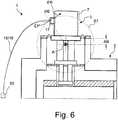
Bei einer alternativen, vorteilhaften Weiterbildung ist vorgesehen, dass der wenigstens eine flexible Abschnitt zumindest in einem Teilbereich gekrümmt verläuft und/oder in verschiedenen Teilbereichen in unterschiedlichen Richtungen verläuft. Dadurch kann die Krafteintragsrichtung freier gewählt werden, und insbesondere abweichend vom Verlauf eines (dem Kaltkopf nahen) Endbereichs des flexiblen Abschnitts eingestellt werden. Oftmals ist auch ein besonders kompakter Bau möglich.In an alternative, advantageous development, it is provided that the at least one flexible section runs curved at least in one partial area and / or runs in different directions in different partial areas. As a result, the force input direction can be chosen more freely, and in particular deviating from the course of an (near the cold head) end portion of the flexible portion can be adjusted. Often, a particularly compact construction is possible.
Bei einer anderen Weiterbildung ist vorgesehen, dass der Krafteintragspunkt an einem dem Kaltkopf nahen Ende des wenigstens einen flexiblen Abschnitts angeordnet ist. Dies ist in der Praxis bewährt und ergibt eine besonders einfache Bauform.In another development, it is provided that the force application point is arranged on an end of the at least one flexible section near the cold head. This is proven in practice and results in a particularly simple design.
Bevorzugt ist weiterhin eine Ausführungsform, bei der die Verbindungsleitung an einem vom Kaltkopf entfernten Ende an sich bewegende Komponenten des Kühlsystems angeschlossen ist, insbesondere an ein Steuerventil oder einen Kompressor. Die sich bewegenden Komponenten können über die Verbindungsleitung entfernt vom Kryostaten positioniert werden, so dass die die Verbindungsleitung die einzige relevante mechanische Verbindung zum Kaltkopf bzw. Kryostaten darstellt, deren Krafteintrag gemäß der Erfindung vom Kryostaten auf einfache Weise ferngehalten werden kann.Also preferred is an embodiment in which the connecting line is connected at a remote from the cold head end to moving components of the cooling system, in particular to a control valve or a compressor. The moving components can be positioned away from the cryostat via the connecting line so that the connecting line is the only relevant mechanical connection to the cold head or cryostat whose force input according to the invention can be kept away from the cryostat in a simple manner.
Vorteilhaft ist weiterhin eine Ausführungsform der erfindungsgemäßen Kühlvorrichtung, die vorsieht, dass der Raumtemperaturabschnitt des Kaltkopfs im Bereich der Befestigung des flexiblen Dichtungsabschnitts einen Durchmesser DM senkrecht zu seiner Längsachse aufweist, und dass für einen Abstand AB der Drehachse von einer Dichtungsebene, in welcher der flexible Dichtungsabschnitt an der Wand des Vakuumbehälters befestigt ist, gilt:
AB ≤ 0,4*DM, bevorzugt AB ≤ 0,3*DM,
insbesondere wobei die Drehachse in der Dichtungsebene angeordnet ist.Also advantageous is an embodiment of the cooling device according to the invention, which provides that the room temperature portion of the cold head in the region of attachment of the flexible sealing portion has a diameter DM perpendicular to its longitudinal axis, and that for a distance AB of the axis of rotation of a sealing plane in which the flexible sealing portion attached to the wall of the vacuum container, the following applies:
AB ≦ 0.4 * DM, preferably AB ≦ 0.3 * DM,
in particular, wherein the axis of rotation is arranged in the sealing plane.
Dadurch kann bei einem flexiblen Dichtungsabschnitt, der einen Spalt zwischen Vakuumbehälterwand und Raumtemperaturteil des Kaltkopfs radial überbrückt, eine Verformung des Dichtabschnitts bei einer Drehbewegung des Kaltkopfs im Wesentlichen axial stattfinden, was der Dichtabschnitt ohne Spannungsaufbau mitmachen kann. Der flexible Dichtabschnitt ist in der Regel in axialer Richtung ausgewölbt.As a result, in the case of a flexible sealing section which radially bridges a gap between the vacuum container wall and the room temperature part of the cold head, a deformation of the sealing section essentially takes place axially during a rotary movement of the cold head, which the sealing section can join without stress build-up. The flexible sealing portion is generally bulged in the axial direction.
Bei einer vorteilhaften Ausführungsform sind der Kaltkopf und der Kryostat entlang einer Längsachse des Kaltkopfs gegeneinander verstellbar ausgebildet. Dadurch kann der Kaltkopf gegenüber dem Kryostaten ausgerichtet werden, insbesondere um Berührungen des Kaltkopfs am Kryostaten bei einer Drehbewegung zu vermeiden und die erforderlichen kleinen Spalte zwischen den Kühlstufen des Kaltkopfs und dem Kryostaten trotz der unvermeidlichen Fertigungstoleranzen einfach einstellen zu können. Typischerweise ist das Drehlager gegenüber dem Kryostaten fest positioniert.In an advantageous embodiment, the cold head and the cryostat along a longitudinal axis of the cold head are adjustable relative to each other. As a result, the cold head can be aligned with respect to the cryostat, in particular to avoid contact of the cold head on the cryostat during a rotary movement and to be able to easily adjust the required small gap between the cooling stages of the cold head and the cryostat despite the inevitable manufacturing tolerances. Typically, the pivot bearing is firmly positioned opposite the cryostat.
Bei einer vorteilhaften Ausführungsform ist vorgesehen, dass das Drehlager mit zwei Lagerzapfen ausgebildet ist, die entlang der Drehachse von einem Kragenabschnitt des Vakuumbehälters auf den Kaltkopf zu ragen, und dass die Lagerzapfen jeweils von einem Kugellager umgriffen werden, wobei die Kugellager starr mit dem Kaltkopf verbunden sind. Um die runden Lagerzapfen können die Kugellager mit minimaler Reibung umlaufen, um die störungsbedingte Drehbewegung des Kaltkopfs gegenüber dem Kryostaten auszuführen. Die Störung wird nicht in den Kryostaten übertragen. Die Lagerzapfen können entlang der Drehachse zurückziehbar ausgebildet sein, um den Kaltkopf zu montieren oder zu demontieren.In an advantageous embodiment, it is provided that the pivot bearing is formed with two bearing journals, which project along the axis of rotation of a collar portion of the vacuum vessel to the cold head, and that the journals each be surrounded by a ball bearing, wherein the ball bearings are rigidly connected to the cold head. The ball bearings can rotate around the round bearing journals with minimal friction in order to carry out the rotational movement of the cold head in relation to the cryostat. The disorder is not transmitted in the cryostat. The journals may be retractable along the axis of rotation to assemble or disassemble the coldhead.
Vorteilhaft ist weiterhin eine Weiterbildung dieser Ausführungsform, bei der die Kugellager in einem Haltering angeordnet sind, der über ein oder mehrere Verstellelemente gegenüber dem Kaltkopf entlang der Längsachse des Kaltkopfs verstellbar ist. Dadurch ist auf einfache Weise eine Verstellbarkeit des Kaltkopfs gegenüber dem Kryostaten einrichtbar. Die Verstellelemente können beispielsweise als Verstellschrauben realisiert sein. Alternativ ist es auch möglich, die Lagerzapfen verstellbar entlang der Längsachse des Kaltkopfs bzw. entlang einer Längsachse der Zugangsöffnung des Kryostaten am Kryostaten auszubilden; in diesem Fall können die Kugellager ortsfest am Kaltkopf angeordnet werden.A further development of this embodiment is advantageous, in which the ball bearings are arranged in a retaining ring which is adjustable via one or more adjusting elements relative to the cold head along the longitudinal axis of the cold head. As a result, an adjustability of the cold head relative to the cryostat can be set up in a simple manner. The adjusting elements can be realized for example as adjusting screws. Alternatively, it is also possible to adjust the bearing pins adjustably along the longitudinal axis of the cold head or along a longitudinal axis of the access opening of the cryostat on the cryostat; In this case, the ball bearings can be arranged stationary on the cold head.
Eine alternative Ausführungsform sieht vor, dass das Drehlager mit zwei Lagerfortsätzen ausgebildet ist, die von einem Kragenabschnitt des Vakuumbehälters auf den Kaltkopf zu ragen, und dass die Lagerfortsätze mit mindestens zwei punktförmigen oder linienförmigen Auflagern ausgebildet sind, die auf der Drehachse A liegen. Diese Lagerung ist besonders reibungsarm, und der Kaltkopf kann einfach von oben auf die Lagerfortsätze aufgesetzt werden.An alternative embodiment provides that the pivot bearing is formed with two bearing extensions, which project from a collar portion of the vacuum container to the cold head, and that the bearing extensions are formed with at least two punctiform or linear supports which lie on the axis of rotation A. This storage is particularly low friction, and the cold head can be easily placed on top of the bearing extensions.
Bei einer bevorzugten Ausführungsform verläuft die Drehachse horizontal. Dadurch lässt sich der Kaltkopf gut in vertikaler Richtung von oben in einen Kryostaten hinein hängend positionieren.In a preferred embodiment, the axis of rotation is horizontal. As a result, the cold head can be well positioned in a vertical direction from above into a cryostat in a hanging position.
In den Rahmen der vorliegenden Erfindung fällt auch eine NMR-Messanordnung, umfassend eine oben beschriebene, erfindungsgemäße Kühlvorrichtung, eine Magnetspulenanordnung im Kryobehälter sowie einen ein Probenvolumen umgebenden HF-Resonator in einer Raumtemperaturbohrung des Kryostaten. Die NMR-Messanordnung kann besonders störungsarm betrieben werden.The scope of the present invention also includes an NMR measuring arrangement comprising a cooling device according to the invention described above, a magnet coil arrangement in the cryocontainer and an RF resonator surrounding a sample volume in a room temperature bore of the cryostat. The NMR measuring arrangement can be operated with particularly low interference.
Weitere Vorteile der Erfindung ergeben sich aus der Beschreibung und den Zeichnungen. Ebenso können die vorstehend genannten und die weiter aufgeführten Merkmale je für sich oder zu mehreren in beliebigen Kombinationen Verwendung finden. Die gezeigten und beschriebenen Ausführungsformen sind nicht als abschließende Aufzählung zu verstehen, sondern haben vielmehr beispielhaften Charakter für die Schilderung der Erfindung.Further advantages of the invention will become apparent from the description and the drawings. Likewise, the features mentioned above and those listed further can be used individually or in any combination. The embodiments shown and described are not to be understood as exhaustive enumeration, but rather have exemplary character for the description of the invention.
Figurenlistelist of figures
Die Erfindung ist in der Zeichnung dargestellt und wird anhand von Ausführungsbeispielen näher erläutert. Es zeigen:
1a eine schematische Querschnittsdarstellung einer ersten Ausführungsform einer erfindungsgemäßen Kühlvorrichtung, mit horizontaler Verbindungsleitung;1b eine schematische Aufsicht auf den Kaltkopf der Kühlvorrichtung von1a , mit in der Lagerebene verlaufender Verbindungsleitung;1c eine schematische Aufsicht auf einen Kaltkopf einer Kühlvorrichtung, in einer Variante mit einer schräg zur Lagerebene verlaufenden Verbindungsleitung;2 eine schematische Querschnittsdarstellung einer zweiten Ausführungsform einer erfindungsgemäßen Kühlvorrichtung, mit höhenverstellbarem Kaltkopf;3 eine schematische, teilweise geschnittene Schrägansicht der dritten Ausführungsform einer Kühlvorrichtung, mit Kugellager im Haltering des Kaltkopfs zum Umgreifen zweier Lagerzapfen;4 eine schematische, teilweise geschnittene Schrägansicht einer vierten Ausführungsform einer erfindungsgemäßen Kühlvorrichtung, mit punktförmigen Auflagern an Lagerfortsätzen;5 eine schematische Querschnittsdarstellung einer fünften Ausführungsform einer erfindungsgemäßen Kühlvorrichtung, mit einem schräg zur Horizontalen verlaufenden flexiblen Abschnitt in der Verbindungsleitung;6 eine schematische Querschnittsdarstellung einer sechsten Ausführungsform einer erfindungsgemäßen Kühlvorrichtung, mit einer gekrümmt verlaufenden flexiblen Abschnitt in der Verbindungsleitung;7 eine schematische Seitenansicht einer erfindungsgemäßen NMR-Messanordnung.
1a a schematic cross-sectional view of a first embodiment of a cooling device according to the invention, with horizontal connecting line;1b a schematic plan view of the cold head of the cooling device of1a with connecting line running in the storage level;1c a schematic plan view of a cold head of a cooling device, in a variant with a running obliquely to the bearing plane connecting line;2 a schematic cross-sectional view of a second embodiment of a cooling device according to the invention, with height-adjustable cold head;3 a schematic, partially sectioned oblique view of the third embodiment of a cooling device, with ball bearings in the retaining ring of the cold head for encompassing two journals;4 a schematic, partially sectioned oblique view of a fourth embodiment of a cooling device according to the invention, with punctiform supports of bearing extensions;5 a schematic cross-sectional view of a fifth embodiment of a cooling device according to the invention, with an obliquely extending to the horizontal flexible portion in the connecting line;6 a schematic cross-sectional view of a sixth embodiment of a cooling device according to the invention, with a curved extending flexible portion in the connecting line;7 a schematic side view of an NMR measuring device according to the invention.
Die
Die Kühlvorrichtung
Der Kaltkopf
Die Umgebung des Kühlarms
Der Kaltkopf
Der Kaltkopf
Durch die Druckstöße des Arbeitsgases wirkt entsprechend periodisch entlang einer Krafteintragsrichtung ER eine Kraft an einem Krafteintragspunkt EP auf den Kaltkopf
Die Krafteintragsrichtung ER schließt einen Winkel γ mit einer Normalen N auf einer Hebelebene HE ein. Die Normale steht senkrecht auf der Hebelebene; ein Endpunkt der Normalen N ist auf den Krafteintragspunkt EP gelegt. Die Hebelebene HE enthält die Drehachse A und den Krafteintragspunkt EP.The force input direction ER includes an angle γ with a normal N on a lever plane HE. The normal is perpendicular to the lever plane; an end point of the normal N is placed on the force input point EP. The lever plane HE contains the axis of rotation A and the force input point EP.
In der gezeigten Ausführungsform liegt die Krafteintragsrichtung ER in einer Lagerebene LE. Die Lagerebene LE verläuft senkrecht zur Drehachse A und enthält den Krafteintragspunkt EP. Daher ist der Winkel γ hier gleich einem Winkel β, der zwischen der Krafteintragsrichtung ER und einer Lotebene OE gemessen wird, wobei die Lotebene OE senkrecht zur Hebelebene HE verläuft und den Krafteintragspunkt EP enthält.In the embodiment shown, the force input direction ER is in a bearing plane LE. The bearing plane LE runs perpendicular to the axis of rotation A and contains the force input point EP. Therefore, the angle γ here is equal to an angle β, which is measured between the force input direction ER and a solder plane OE, wherein the solder plane OE is perpendicular to the lever plane HE and contains the force input point EP.
Der Winkel γ bzw. β beträgt in der gezeigten Ausführungsform ca. 30°, so dass der größte Teil der Krafteinwirkung entlang der Richtung der Normalen N wirkt. Aufgrund des Drehlagers kann der Kaltkopf
Man beachte, dass durch kleinere Winkel γ der Krafteintragsrichtung ER gegenüber der Normalen N der Hebelebene HE verbleibende, über das Drehlager auf den Kryostaten
Ein Abstand AB der Drehachse A von einer Dichtungsebene DE, in welcher der flexible Leitungsabschnitt
Die
Falls die Krafteintragsrichtung ER einen nicht verschwindenden Winkel α mit der Lagerebene LE einschließt, vgl.
Man beachte, dass der Winkel γ zur Normalen der Hebelebene einen Beitrag aus α und einen Beitrag aus β haben kann.Note that the angle γ to the normal of the lever plane may have a contribution from α and a contribution from β.
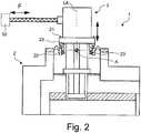
Die Kühlvorrichtung
Durch die Verstellbarkeit kann der Schwerpunkt des Kaltkopfs
Von einem Kragenabschnitt
In
Das Drehlager
Bei dieser Ausführungsform umfasst die Verbindungsleitung
Der Winkel α der Krafteintragsrichtung ER zur Lagerebene LE beträgt hier ebenfalls 0° (nicht näher dargestellt), so dass durch das Kühlsystem
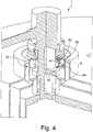
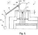
Die
Die Verbindungsleitung
Der flexible Abschnitt
In der
Eine ähnliche mechanische Wirkung wie durch einen gekrümmten flexiblen Abschnitt der Verbindungsleitung kann auch durch zwei gerade verlaufende, zueinander schräge, hintereinander eingesetzte flexible Leitungsabschnitte erzielt werden (nicht näher dargestellt).A similar mechanical effect as by a curved flexible portion of the connecting line can also be achieved by two straight, mutually inclined, consecutively used flexible line sections (not shown in detail).
Die
Claims (20)
Translated fromGermanPriority Applications (4)
| Application Number | Priority Date | Filing Date | Title |
|---|---|---|---|
| DE102016206435.5ADE102016206435B4 (en) | 2016-04-15 | 2016-04-15 | Cooling device comprising a cryostat and a cold head, with improved decoupling to a cooling system and associated NMR measuring arrangement |
| JP2017075141AJP6564415B2 (en) | 2016-04-15 | 2017-04-05 | Cooling device with a cryostat and cold head for improved isolation from the cooling system |
| EP17165148.2AEP3232143B1 (en) | 2016-04-15 | 2017-04-06 | Cooling device comprising a cryostat and a cooling head, with improved decoupling from a cooling system |
| US15/487,089US10401447B2 (en) | 2016-04-15 | 2017-04-13 | Cooling device, comprising a cryostat and a cold head having improved decoupling to a cooling system |
Applications Claiming Priority (1)
| Application Number | Priority Date | Filing Date | Title |
|---|---|---|---|
| DE102016206435.5ADE102016206435B4 (en) | 2016-04-15 | 2016-04-15 | Cooling device comprising a cryostat and a cold head, with improved decoupling to a cooling system and associated NMR measuring arrangement |
Publications (2)
| Publication Number | Publication Date |
|---|---|
| DE102016206435A1 DE102016206435A1 (en) | 2017-10-19 |
| DE102016206435B4true DE102016206435B4 (en) | 2018-05-17 |
Family
ID=58501258
Family Applications (1)
| Application Number | Title | Priority Date | Filing Date |
|---|---|---|---|
| DE102016206435.5AActiveDE102016206435B4 (en) | 2016-04-15 | 2016-04-15 | Cooling device comprising a cryostat and a cold head, with improved decoupling to a cooling system and associated NMR measuring arrangement |
Country Status (4)
| Country | Link |
|---|---|
| US (1) | US10401447B2 (en) |
| EP (1) | EP3232143B1 (en) |
| JP (1) | JP6564415B2 (en) |
| DE (1) | DE102016206435B4 (en) |
Families Citing this family (4)
| Publication number | Priority date | Publication date | Assignee | Title |
|---|---|---|---|---|
| GB2513151B (en)* | 2013-04-17 | 2015-05-20 | Siemens Plc | Improved thermal contact between cryogenic refrigerators and cooled components |
| CN108022711B (en)* | 2018-01-02 | 2020-06-12 | 中国科学院电工研究所 | An Intelligent Magnetic Resonance Whole Body Imaging Superconducting Magnet System |
| GB2576185B (en) | 2018-08-08 | 2022-07-20 | Oxford Instruments Nanotechnology Tools Ltd | Noise reduction method for a cryogenic cooling system |
| EP4127575A4 (en) | 2020-03-30 | 2024-07-24 | Sumitomo (Shi) Cryogenics of America, Inc. | IMPROVED CONNECTION CABLE FOR SPLIT IMPULSE TUBES |
Citations (5)
| Publication number | Priority date | Publication date | Assignee | Title |
|---|---|---|---|---|
| EP0780698A1 (en) | 1995-12-22 | 1997-06-25 | Spectrospin Ag | NMR apparatus with pulse tube refrigerator |
| US20050229620A1 (en) | 2004-04-15 | 2005-10-20 | Oxford Instruments Superconductivity Ltd. | Cooling apparatus |
| US20120073310A1 (en) | 2006-10-10 | 2012-03-29 | Massachusetts Institute Of Technology | Cryogenic vacuum break thermal coupler |
| DE102014214819B3 (en) | 2014-07-29 | 2015-08-20 | Bruker Biospin Gmbh | Pulse tube cooler system with force-compensated rotary valve line |
| DE102014219849B3 (en) | 2014-09-30 | 2015-12-10 | Bruker Biospin Gmbh | Cooling device with cryostat and cold head with reduced mechanical coupling |
Family Cites Families (13)
| Publication number | Priority date | Publication date | Assignee | Title |
|---|---|---|---|---|
| DE19533555A1 (en) | 1995-09-11 | 1997-03-13 | Siemens Ag | Device for indirect cooling of an electrical device |
| US5864273A (en)* | 1997-03-12 | 1999-01-26 | General Electric Company | Cryocooler vibration isolation and noise reduction in magnetic resonance imaging |
| JPH10282200A (en)* | 1997-04-09 | 1998-10-23 | Aisin Seiki Co Ltd | Superconducting magnet system cooling system |
| JP4494027B2 (en)* | 2004-01-26 | 2010-06-30 | 株式会社神戸製鋼所 | Cryogenic equipment |
| JP2006141655A (en)* | 2004-11-19 | 2006-06-08 | Hitachi Ltd | Superconducting magnet apparatus and magnetic resonance imaging apparatus using the same |
| DE102005004269B4 (en)* | 2005-01-29 | 2006-11-02 | Bruker Biospin Gmbh | Magnetic resonance apparatus with in-phase coupling of pressure pulses of a working gas |
| JP2008035604A (en) | 2006-07-27 | 2008-02-14 | Sumitomo Heavy Ind Ltd | Gm freezer, pulse tube freezer, cryopump, mri device, super-conductive magnet system, nmr device, and freezer for cooling of semiconductor |
| US8291717B2 (en) | 2008-05-02 | 2012-10-23 | Massachusetts Institute Of Technology | Cryogenic vacuum break thermal coupler with cross-axial actuation |
| US20090293505A1 (en)* | 2008-05-29 | 2009-12-03 | Cryomech, Inc. | Low vibration liquid helium cryostat |
| JP5283096B2 (en)* | 2012-03-09 | 2013-09-04 | 住友重機械工業株式会社 | Cryogenic cooling device |
| GB201208838D0 (en)* | 2012-05-18 | 2012-07-04 | Oxford Instr Nanotechnology Tools Ltd | Apparatus for reducing noise in a cryocooler |
| GB2513151B (en)* | 2013-04-17 | 2015-05-20 | Siemens Plc | Improved thermal contact between cryogenic refrigerators and cooled components |
| US10181372B2 (en)* | 2013-04-24 | 2019-01-15 | Siemens Healthcare Limited | Assembly comprising a two-stage cryogenic refrigerator and associated mounting arrangement |
- 2016
- 2016-04-15DEDE102016206435.5Apatent/DE102016206435B4/enactiveActive
- 2017
- 2017-04-05JPJP2017075141Apatent/JP6564415B2/enactiveActive
- 2017-04-06EPEP17165148.2Apatent/EP3232143B1/enactiveActive
- 2017-04-13USUS15/487,089patent/US10401447B2/enactiveActive
Patent Citations (5)
| Publication number | Priority date | Publication date | Assignee | Title |
|---|---|---|---|---|
| EP0780698A1 (en) | 1995-12-22 | 1997-06-25 | Spectrospin Ag | NMR apparatus with pulse tube refrigerator |
| US20050229620A1 (en) | 2004-04-15 | 2005-10-20 | Oxford Instruments Superconductivity Ltd. | Cooling apparatus |
| US20120073310A1 (en) | 2006-10-10 | 2012-03-29 | Massachusetts Institute Of Technology | Cryogenic vacuum break thermal coupler |
| DE102014214819B3 (en) | 2014-07-29 | 2015-08-20 | Bruker Biospin Gmbh | Pulse tube cooler system with force-compensated rotary valve line |
| DE102014219849B3 (en) | 2014-09-30 | 2015-12-10 | Bruker Biospin Gmbh | Cooling device with cryostat and cold head with reduced mechanical coupling |
Also Published As
| Publication number | Publication date |
|---|---|
| EP3232143B1 (en) | 2020-01-01 |
| US20170299673A1 (en) | 2017-10-19 |
| DE102016206435A1 (en) | 2017-10-19 |
| EP3232143A1 (en) | 2017-10-18 |
| US10401447B2 (en) | 2019-09-03 |
| JP2017207270A (en) | 2017-11-24 |
| JP6564415B2 (en) | 2019-08-21 |
Similar Documents
| Publication | Publication Date | Title |
|---|---|---|
| DE102016206435B4 (en) | Cooling device comprising a cryostat and a cold head, with improved decoupling to a cooling system and associated NMR measuring arrangement | |
| DE102014219849B3 (en) | Cooling device with cryostat and cold head with reduced mechanical coupling | |
| DE102014218773B4 (en) | Automatic thermal decoupling of a cooling head | |
| DE19734138B4 (en) | Low-noise MRI scanner | |
| EP1736723B1 (en) | Cryostatic device with cryocooler | |
| DE69838866T2 (en) | Improvements in or related to cryostat systems | |
| DE102006020772B3 (en) | Cooled NMR probe head with flexible cooled connection line | |
| DE102011006164B4 (en) | Compact cryogenic NMR sensor with integrated, active cooling unit | |
| WO1997010469A1 (en) | Indirect cooling system for an electrical device | |
| DE102016214731B3 (en) | NMR apparatus with superconducting magnet arrangement and cooled probe components | |
| DE102019209160B3 (en) | Cryostat arrangement with resilient, thermally conductive connecting element | |
| EP1909111B1 (en) | Vacuum container for a cooled magnetic resonance sensor head | |
| DE19548273A1 (en) | NMR measuring device with pulse tube cooler | |
| EP0116364A1 (en) | Cooling device for a low temperature magnetic system | |
| DE10006324C1 (en) | Cooled NMR probe head with device for centering the measurement sample | |
| EP3209954B1 (en) | Optical table | |
| DE102011115303B4 (en) | Cryogenic device | |
| DE10236471A1 (en) | Magnetic bearing for a rotor shaft has permanent magnets attached to the air sealed shaft rotating within an air gap to a superconducting magnetic field | |
| DE102014214819B3 (en) | Pulse tube cooler system with force-compensated rotary valve line | |
| EP3611528B1 (en) | Cryostat arrangement with superconducting magnetic coil system with thermal anchoring of the fixing structure | |
| DE102007008513A1 (en) | Arrangement with a basic field magnet and with a gradient coil of a magnetic resonance apparatus | |
| EP0769667B1 (en) | Refrigerating and/or freezing apparatus | |
| DE102005042834B4 (en) | Superconducting magnet system with refrigerator for the re-liquefaction of cryofluid in a pipeline | |
| EP0501203B1 (en) | Cryomagnetsystem having a low-loss helium cryostat with minimised disturbance | |
| DE102004023072B4 (en) | Magnet system with shielded regenerator material and method of operation of the magnet system |
Legal Events
| Date | Code | Title | Description |
|---|---|---|---|
| R012 | Request for examination validly filed | ||
| R016 | Response to examination communication | ||
| R018 | Grant decision by examination section/examining division | ||
| R020 | Patent grant now final | ||
| R081 | Change of applicant/patentee | Owner name:BRUKER SWITZERLAND AG, CH Free format text:FORMER OWNER: BRUKER BIOSPIN AG, FAELLANDEN, CH | |
| R082 | Change of representative | Representative=s name:KOHLER SCHMID MOEBUS PATENTANWAELTE PARTNERSCH, DE |