DE102016204969A1 - Apparatus and method for producing a fibrous web in a paper machine - Google Patents
Apparatus and method for producing a fibrous web in a paper machineDownload PDFInfo
- Publication number
- DE102016204969A1 DE102016204969A1DE102016204969.0ADE102016204969ADE102016204969A1DE 102016204969 A1DE102016204969 A1DE 102016204969A1DE 102016204969 ADE102016204969 ADE 102016204969ADE 102016204969 A1DE102016204969 A1DE 102016204969A1
- Authority
- DE
- Germany
- Prior art keywords
- fibrous web
- multilayer fibrous
- forming unit
- press
- layer
- Prior art date
- Legal status (The legal status is an assumption and is not a legal conclusion. Google has not performed a legal analysis and makes no representation as to the accuracy of the status listed.)
- Ceased
Links
- 238000004519manufacturing processMethods0.000titleclaimsdescription10
- 238000012546transferMethods0.000claimsabstractdescription55
- 238000003825pressingMethods0.000claimsabstractdescription19
- 238000001035dryingMethods0.000claimsabstractdescription15
- 238000009499grossingMethods0.000claimsabstractdescription10
- 235000000391Lepidium drabaNutrition0.000claimsdescription4
- 239000002655kraft paperSubstances0.000claimsdescription2
- 239000011098white lined chipboardSubstances0.000claimsdescription2
- 230000015572biosynthetic processEffects0.000abstractdescription4
- 239000010410layerSubstances0.000description69
- 239000000725suspensionSubstances0.000description9
- 239000003381stabilizerSubstances0.000description7
- 238000013461designMethods0.000description5
- 239000000123paperSubstances0.000description5
- 238000011161developmentMethods0.000description4
- 239000000835fiberSubstances0.000description3
- 239000000203mixtureSubstances0.000description3
- 239000002250absorbentSubstances0.000description2
- 238000006243chemical reactionMethods0.000description2
- 230000000694effectsEffects0.000description2
- 238000009434installationMethods0.000description2
- 238000004806packaging method and processMethods0.000description2
- 239000011241protective layerSubstances0.000description2
- BUHVIAUBTBOHAG-FOYDDCNASA-N(2r,3r,4s,5r)-2-[6-[[2-(3,5-dimethoxyphenyl)-2-(2-methylphenyl)ethyl]amino]purin-9-yl]-5-(hydroxymethyl)oxolane-3,4-diolChemical compoundCOC1=CC(OC)=CC(C(CNC=2C=3N=CN(C=3N=CN=2)[C@H]2[C@@H]([C@H](O)[C@@H](CO)O2)O)C=2C(=CC=CC=2)C)=C1BUHVIAUBTBOHAG-FOYDDCNASA-N0.000description1
- 241000252254CatostomidaeSpecies0.000description1
- 229920002472StarchPolymers0.000description1
- 230000002146bilateral effectEffects0.000description1
- 239000000969carrierSubstances0.000description1
- 239000011248coating agentSubstances0.000description1
- 238000000576coating methodMethods0.000description1
- 230000006735deficitEffects0.000description1
- 230000018044dehydrationEffects0.000description1
- 238000006297dehydration reactionMethods0.000description1
- 230000002708enhancing effectEffects0.000description1
- 239000004744fabricSubstances0.000description1
- 238000003780insertionMethods0.000description1
- 230000037431insertionEffects0.000description1
- 239000011159matrix materialSubstances0.000description1
- 239000002184metalSubstances0.000description1
- 238000000034methodMethods0.000description1
- 239000010893paper wasteSubstances0.000description1
- 239000000049pigmentSubstances0.000description1
- 239000004033plasticSubstances0.000description1
- 230000003014reinforcing effectEffects0.000description1
- 235000019698starchNutrition0.000description1
- 239000008107starchSubstances0.000description1
- 230000003068static effectEffects0.000description1
Images

Classifications
- D—TEXTILES; PAPER
- D21—PAPER-MAKING; PRODUCTION OF CELLULOSE
- D21F—PAPER-MAKING MACHINES; METHODS OF PRODUCING PAPER THEREON
- D21F3/00—Press section of machines for making continuous webs of paper
- D21F3/02—Wet presses
- D21F3/04—Arrangements thereof
- D—TEXTILES; PAPER
- D21—PAPER-MAKING; PRODUCTION OF CELLULOSE
- D21F—PAPER-MAKING MACHINES; METHODS OF PRODUCING PAPER THEREON
- D21F11/00—Processes for making continuous lengths of paper, or of cardboard, or of wet web for fibre board production, on paper-making machines
- D21F11/02—Processes for making continuous lengths of paper, or of cardboard, or of wet web for fibre board production, on paper-making machines of the Fourdrinier type
- D21F11/04—Processes for making continuous lengths of paper, or of cardboard, or of wet web for fibre board production, on paper-making machines of the Fourdrinier type paper or board consisting on two or more layers
- D—TEXTILES; PAPER
- D21—PAPER-MAKING; PRODUCTION OF CELLULOSE
- D21F—PAPER-MAKING MACHINES; METHODS OF PRODUCING PAPER THEREON
- D21F9/00—Complete machines for making continuous webs of paper
- D21F9/003—Complete machines for making continuous webs of paper of the twin-wire type
- D21F9/006—Complete machines for making continuous webs of paper of the twin-wire type paper or board consisting of two or more layers
Landscapes
- Paper (AREA)
Abstract
Translated fromGermanDescription
Translated fromGermanDie Erfindung betrifft Vorrichtung zur Herstellung einer mehrlagigen Faserstoffbahn, mit einer Siebpartie zur Bildung einer mehrlagigen Faserstoffbahn, einer Pressenpartie zur weiteren Entwässerung der mehrlagigen Faserstoffbahn und einer Trockenpartie zur Trocknung der mehrlagigen Faserstoffbahn, wobei die Siebpartie mindestens eine erste Formiereinheit zur Bildung einer ersten Lage der mehrlagigen Faserstoffbahn und mindestens eine zweite Formiereinheit zur Bildung einer zweiten Lage der mehrlagigen Faserstoffbahn und eine Vergautschungszone umfasst und die Formiereinheiten zur Ausbildung der mehrlagigen Faserstoffbahn so zueinander angeordnet und ausgebildet sind, dass die zweite Lage der mehrlagigen Faserstoffbahn der zweiten Formiereinheit auf die erste Lage der mehrlagigen Faserstoffbahn der ersten Formiereinheit in der Vergautschungszone zur Ausbildung der mehrlagigen Faserstoffbahn übertragen wird und wobei die Pressenpartie mindestens zwei letzte Pressnips umfasst, wobei die zwei letzten Pressnips durch ein erstes Presselement und ein zweites Presselement und einem gemeinsamen Gegenelement mit glatter Oberfläche zur Glättung einer Seite der mehrlagigen Faserstoffbahn, gebildet sind.The invention relates to apparatus for producing a multilayer fibrous web, comprising a wire section for forming a multilayer fibrous web, a press section for further dewatering the multilayer fibrous web and a dryer section for drying the multilayer fibrous web, wherein the wire section at least a first forming unit for forming a first layer of multilayer Fibrous web and at least one second forming unit for forming a second layer of the multilayer fibrous web and a Vergautschungszone comprises and the forming units for forming the multilayer fibrous web are arranged and configured such that the second layer of the multilayer fibrous web of the second forming unit on the first layer of the multilayer fibrous web the first forming unit is transferred in the Vergautschungszone for forming the multilayer fibrous web and wherein the press section comprises at least two last press nips, wherein the two last press nips are formed by a first pressing element and a second pressing element and a common counter element with a smooth surface for smoothing one side of the multilayer fibrous web.
Die Erfindung betrifft auch ein Verfahren zur Herstellung einer mehrlagigen Faserstoffbahn.The invention also relates to a method for producing a multilayer fibrous web.
Vorrichtungen dieser Art sind aus dem Stand der Technik bekannt. Das Dokument
Im Dokument
Nachteilig bei den bekannten Lösungen sind zum einen die Beeinträchtigung der sogenannten Weiße oder Helligkeit der Deckelage und zum anderen die aufwändige und somit teure Ausführung der Pressenpartie. Neben hohen Investitionskosten sind auch die Betriebskosten durch den Einsatz einer großen Zahl von Bespannungen beträchtlich. Zusätzlich ist das Betriebsverhalten der Maschinenkonzepte mit invertierter Kompaktpresse problematisch.A disadvantage of the known solutions, on the one hand, the impairment of the so-called whiteness or brightness of the cover and on the other hand, the complex and therefore expensive design of the press section. In addition to high investment costs, the operating costs through the use of a large number of fabrics are considerable. In addition, the operating behavior of the machine concepts with inverted compact press is problematic.
Es ist daher Aufgabe der Erfindung eine, gegenüber den bekannten Lösungen, verbesserte Vorrichtung und ein verbessertes Verfahren zur Herstellung einer mehrlagigen Faserstoffbahn, insbesondere zur Herstellung von Liner mit einer Rückenlage und einer weißer Deckelage vorzuschlagen.It is therefore an object of the invention to propose, compared to the known solutions, improved apparatus and an improved method for producing a multilayer fibrous web, in particular for the production of liners with a supine position and a white cover.
Die Aufgabe wird durch die Merkmale des Anspruches 1 gelöst. Es wird eine Vorrichtung zur Herstellung einer mehrlagigen Faserstoffbahn vorgeschlagen, mit einer Siebpartie zur Bildung einer mehrlagigen Faserstoffbahn, einer Pressenpartie zur weiteren Entwässerung der mehrlagigen Faserstoffbahn und einer Trockenpartie zur Trocknung der mehrlagigen Faserstoffbahn, wobei die Siebpartie mindestens eine erste Formiereinheit zur Bildung einer ersten Lage der mehrlagigen Faserstoffbahn und mindestens eine zweite Formiereinheit zur Bildung einer zweiten Lage der mehrlagigen Faserstoffbahn und eine Vergautschungszone umfasst und die Formiereinheiten zur Ausbildung der mehrlagigen Faserstoffbahn so zueinander angeordnet und ausgebildet sind, dass die zweite Lage der mehrlagigen Faserstoffbahn der zweiten Formiereinheit auf die erste Lage der mehrlagigen Faserstoffbahn der ersten Formiereinheit in der Vergautschungszone zur Ausbildung der mehrlagigen Faserstoffbahn übertragen wird und wobei die Pressenpartie mindestens zwei letzte Pressnips umfasst, wobei die zwei letzten Pressnips durch ein erstes Presselement und ein zweites Presselement und einem gemeinsamen Gegenelement mit glatter Oberfläche zur Glättung einer Seite der mehrlagigen Faserstoffbahn, gebildet sind. Die Erfindung zeichnet sich dadurch aus, dass ein Transferband zur direkten Übernahme der mehrlagigen Faserstoffbahn von der ersten Formiereinheit, das heißt von dem Sieb der ersten Formiereinheit, und zum weiteren Transport der mehrlagigen Faserstoffbahn vorgesehen ist und dass ein Pressband zur direkten Übernahme der mehrlagigen Faserstoffbahn von dem Transferband angeordnet ist und dass die mehrlagige Faserstoffbahn zusammen mit dem Pressband derart durch den vorletzten Pressnip geführt ist, dass die zweite Lage der mehrlagigen Faserstoffbahn in Kontakt mit der glatten Oberfläche des Gegenelementes kommt.The object is solved by the features of claim 1. It is proposed an apparatus for producing a multilayer fibrous web, comprising a wire section for forming a multilayer fibrous web, a press section for further dewatering of the multilayer fibrous web and a dryer section for drying the multilayer fibrous web, wherein the wire section at least a first forming unit for forming a first layer of multi-layer fibrous web and at least one second forming unit for forming a second layer of the multilayer fibrous web and a Vergautschungszone comprises and the forming units for forming the multilayer fibrous web are arranged and configured so that the second layer of the multilayer fibrous web of the second forming unit on the first layer of the multilayer Is transferred fibrous web of the first forming unit in the Vergautschungszone to form the multilayer fibrous web and wherein the press section comprises at least two last press nips, wherein the two last press nips are formed by a first pressing element and a second pressing element and a common counter-element with a smooth surface for smoothing one side of the multilayer fibrous web. The invention is characterized in that a transfer belt for direct takeover of the multi-ply fibrous web from the first forming unit, that is from the screen of the first forming unit, and for further transport of the multilayer fibrous web is provided and that a press belt for direct takeover of the multilayer fibrous web of the transfer belt is arranged and that the multilayer fibrous web is guided together with the press belt in such a way by the penultimate press nip, that the second Position of the multilayer fibrous web comes into contact with the smooth surface of the counter element.
Diese Lösung hat den Vorteil, dass die Qualität, z. Bsp. die Weiße oder Helligkeit, der zweite Lage der mehrlagigen Faserstoffbahn in der Siebpartie durch die Entwässerung nicht beeinträchtigt wird und gleichzeitig eine konventionelle, einfache Pressenpartie mit einer Kompaktpresse ohne Transferbänder zur Glättung der zum gemeinsamen Gegenelement weisenden Seite der zweiten Lage der mehrlagigen Faserstoffbahn einsetzbar ist. Dadurch verbessert sich auch das Betriebsverhalten, insbesondere hinsichtlich auftretender Randfalten oder Randeinrisse in der Faserstoffbahn. Zudem ist die Entwässerungskapazität ausreichend da die Presse zwei Pressnips mit jeweils mindestens einem wasseraufnehmenden Filz aufweist. Ebenso wird die Glätte der zweiten Lage durch die Glättwirkung von zwei Pressnips, genauer gesagt durch die beiden letzten Pressnips, verbessert.This solution has the advantage that the quality, eg. For example, the whiteness or brightness, the second layer of the multi-ply fibrous web in the wire section is not affected by the drainage and at the same time a conventional, simple press section with a compact press without transfer belts for smoothing the common counter element facing side of the second layer of the multilayer fibrous web is used , This also improves the operating behavior, in particular with regard to occurring edge folds or edge tears in the fibrous web. In addition, the dewatering capacity is sufficient because the press has two press nips, each with at least one water-absorbent felt. Likewise, the smoothness of the second layer is improved by the smoothing effect of two press nips, more precisely by the last two press nips.
In einer möglichen Ausgestaltung der Erfindung sind die mindestens eine erste und/oder die mindestens eine zweite Formiereinheit als Langsieb ausgebildet.In one possible embodiment of the invention, the at least one first and / or the at least one second forming unit are formed as a wire.
In einer Weiterentwicklung ist es möglich das Langsieb der mindestens einen ersten und/oder der mindestens einen zweiten Formiereinheit mit einem Obersieb auszustatten, um die jeweilige Lage nach beiden Seiten zu entwässern. Dies kann dem Zweck einer Steigerung der Entwässerungsleistung, als auch der Qualitätssteigerung dienen.In a further development, it is possible to equip the wire of the at least one first and / or the at least one second forming unit with a top wire in order to dewater the respective layer to both sides. This may serve the purpose of increasing dewatering performance as well as enhancing quality.
In einem praktischen Fall sind der mindestens einen ersten und der mindestens einen zweiten Formiereinheit ein Stoffauflauf zur Beaufschlagung der entsprechenden Formiereinheit mit einer Faserstoffsuspension zugeordnet.In a practical case, the at least one first and the at least one second forming unit are assigned a headbox for impinging the corresponding forming unit with a pulp suspension.
In einer möglichen praktischen Ausführung weist die Faserstoffsuspension für die erste Formiereinheit eine andere Zusammensetzung als die Faserstoffsuspension für die zweite Formiereinheit auf. So kann beispielsweise die Faserstoffsuspension für die erste Formiereinheit zumindest teilweise ungebleichten Zellstoff und/oder Altpapier enthalten und die Faserstoffsuspension für die zweite Formiereinheit einen helleren Faserstoff enthalten.In one possible practical embodiment, the pulp suspension for the first forming unit has a different composition than the pulp suspension for the second forming unit. For example, the pulp suspension for the first forming unit may contain at least partially unbleached pulp and / or waste paper, and the pulp suspension for the second forming unit may contain a lighter pulp.
In einer bevorzugten Ausführungsform ist die Vorrichtung ausgebildet zur Herstellung einer Faserstoffbahn aus der Gruppe von Liner, White Top Testliner, White Top Kraft Liner oder White Lined Chipboard. Dabei bildet die erste Lage die dunklere Rückenlage und die zweite Lage die hellere Deckelage mit höherem Weißewert der mehrlagigen Faserstoffbahn. Das Flächengewicht der mehrlagigen Faserstoffbahn liegt vorzugsweise im Bereich von 70 bis 250 g/m2,In a preferred embodiment, the device is designed to produce a fibrous web from the group of liners, white top testliner, white top kraft liner or white lined chipboard. The first layer forms the darker supine position and the second layer the lighter cover layer with higher white value of the multilayer fibrous web. The basis weight of the multilayer fibrous web is preferably in the range of 70 to 250 g / m2 ,
In einer weiteren möglichen Ausgestaltung kann die Vorrichtung mindestens eine weitere Formiereinheit zur Bildung mindestens einer weiteren Lage der mehrlagigen Faserstoffbahn umfassen, wobei die Vorrichtung so ausgebildet und angeordnet ist, dass die weitere Lage zwischen der Deckelage und der Rückenlage der mehrlagigen Faserstoffbahn angeordnet ist. Die weitere Formiereinheit kann der ersten und/oder der zweiten Formiereinheit zugeordnet sein. Die auf der mindestens einen weiteren Formiereinheit erzeugte weitere Lage wird dabei auf die erste und/oder die zweite Formiereinheit zur Ausbildung der ersten und/oder zweiten Lage übertragen. Bei der Herstellung von Liner kann die mindestens eine weitere Lage die Schonschicht bilden.In a further possible embodiment, the device may comprise at least one further forming unit for forming at least one further layer of the multilayer fibrous web, wherein the device is designed and arranged such that the further layer is arranged between the cover layer and the backsheet of the multilayer fibrous web. The further forming unit can be assigned to the first and / or the second forming unit. The further layer produced on the at least one further forming unit is transferred to the first and / or the second forming unit for forming the first and / or second layer. In the production of liners, the at least one further layer can form the protective layer.
In einer vorteilhaften Ausführungsform ist der der ersten Formiereinheit zugeordnete Stoffauflauf als Mehrschichtstoffauflauf ausgeführt.In an advantageous embodiment, the headbox associated with the first forming unit is designed as a multi-layer headbox.
Gemäß einer praktischen Weiterentwicklung ist der ersten Formiereinheit und/oder der zweiten Formiereinheit ein Sekundärstoffauflauf zur Aufbringung einer weiteren Faserstoffsuspension auf eine vorentwässerte Faserstoffbahn der jeweiligen Formiereinheit zugeordnet. Der Sekundärstoffauflauf ist in Laufrichtung nach dem Stoffauflauf der jeweiligen Formiereinheit an einer Stelle angeordnet, an der die durch den Stoffauflauf aufgebrachte Faserstoffsuspension teilweise entwässert ist.According to a practical development of the first forming unit and / or the second forming unit is associated with a Sekundärstoffauflauf for applying a further pulp suspension to a pre-dewatered fibrous web of the respective forming unit. The secondary casserole is arranged in the direction of the headbox of the respective forming unit at a point at which the pulp suspension applied through the headbox is partially dewatered.
In einer weiteren vorteilhaften Ausführungsform ist der der zweiten Formiereinheit zugeordnete Stoffauflauf als Mehrschichtstoffauflauf ausgeführt.In a further advantageous embodiment, the headbox associated with the second forming unit is designed as a multi-layer headbox.
Eine in Maschinenlaufrichtung kurze Bauform kann durch die Anordnung der zweiten Formiereinheit oberhalb der ersten Formiereinheit erreicht werden.A short design in the machine direction can be achieved by arranging the second forming unit above the first forming unit.
In bestimmten Fällen ist es vorteilhaft, wenn die zweite Formiereinheit im Wesentlichen auf gleichem Niveau neben, das heißt in Maschinenlaufrichtung vor der ersten Formiereinheit angeordnet ist. Dies ist insbesondere bei Umbauten oder bei Neuanlagen in vorhandenen Gebäuden bei niedriger Kranhakenhöhe von Vorteil.In certain cases, it is advantageous if the second forming unit is arranged substantially at the same level next to, that is in the machine direction, before the first forming unit. This is particularly advantageous for conversions or new installations in existing buildings at low crane hook height advantage.
In einem praktischen Fall ist das gemeinsame Gegenelement als glatte Walze ausgebildet. Dies ist eine kompakte, kostengünstige und betriebssichere Lösung.In a practical case, the common counter-element is formed as a smooth roller. This is a compact, cost-effective and reliable solution.
Es ist auch denkbar, wenn als gemeinsames Gegenelement eine von einem Band mit glatter Oberfläche zur Glättung der Faserstoffbahn umschlungenen Walze vorgesehen ist. Diese Lösung kann vorteilhaft sein, wenn ein völlig gestützter Bahntransfer zur nachfolgenden Trockenpartie gewünscht ist. Dies kann beispielsweise bei der Herstellung von Faserstoffbahnen mit geringer Nassfestigkeit vorteilhaft sein. Ferner ist es auch möglich, wenn in Maschinenlaufrichtung gesehen vor dem vorletzten Pressnip ein weiterer Pressnip angeordnet ist.It is also conceivable, if as a common counter-element a belt looped by a smooth surface for smoothing the fibrous web is provided. This solution can be advantageous if a fully supported web transfer to the subsequent dryer section is desired. This may be advantageous, for example, in the production of fibrous webs with low wet strength. Furthermore, it is also possible, when seen in the machine direction before the penultimate press nip another press nip is arranged.
In einer vorteilhaften praktischen Ausführung ist der weitere Pressnip durch das erste Presselement und einer Gegenwalze gebildet, wobei die mehrlagige Faserstoffbahn zwischen dem Pressband und einem Filzband liegend durch den weiteren Pressnip geführt ist. Die Gegenwalze kann als Saugpresswalze ausgeführt sein. Das Pressband kann als Filzband ausgeführt sein.In an advantageous practical embodiment of the further press nip is formed by the first pressing member and a counter-roller, wherein the multi-layer fibrous web is guided lying between the press belt and a felt belt through the further press nip. The counter roll can be designed as a suction press roll. The press belt can be designed as a felt belt.
Vorteilhafterweise ist das Transferband permeabel ausgeführt. Es kann ohne Naht als auch mit Naht ausgeführt sein.Advantageously, the transfer belt is made permeable. It can be executed without seam or with seam.
Ferner ist es möglich, das Transferband als gewobenes Sieb oder als Band aus einer gegossenen Kunstoffmatrix mit integrierten Verstärkungsfäden oder als beheizbares Metallband auszubilden.Furthermore, it is possible to form the transfer belt as a woven wire or as a band of a cast plastic matrix with integrated reinforcing threads or as a heatable metal strip.
Ein Wechseln des Transferbandes ist möglich, wenn die Stuhlung mit Cantileverträger ausgerüstet sind. Es ist jedoch auch die kostengünstigere Lösung ohne Cantileverträger denkbar. In diesem Falle ist das Transferband mit Naht ausgeführt oder die vertikalen Stuhlungsträger sind auf der Bedienseite (Führerseite) mit bekannten Einführvorrichtungen zum automatischen Durchführen der Transferbandes durch die belasteten vertikalen Stuhlungsträger.A change of the transfer band is possible if the staging are equipped with Cantileverträger. However, it is also the cheaper solution without Cantileverträger conceivable. In this case, the transfer belt is executed with seam or the vertical stool carriers are on the operating side (leader side) with known insertion devices for automatically passing the transfer belt through the loaded vertical Staune carrier.
In einer praktischen Ausführungsform sind innerhalb der Schlaufe des Siebes
Zweckmäßigerweise ist innerhalb der Schlaufe des Transferbandes im Bereich der Übernahmestelle der mehrlagigen Faserstoffbahn von der ersten Formiereinheit ein Saugelement angeordnet. Das Saugelement kann als Saugkasten oder als Saugwalze ausgeführt sein. Dadurch kann eine betriebssichere Übernahme der mehrlagigen Faserstoffbahn von dem Sieb der ersten Formiereinheit zum Transferband ermöglicht werden. Die Wirkung des Saugelements ist dabei so ausgeführt, dass im Wesentlichen keine Entwässerung der Faserstoffbahn stattfindet, sondern lediglich die Übernahme der Faserstoffbahn verbessert wird. Der Unterdruck des Saugelements ist kleiner oder gleich als 30kPa, vorzugsweise gleich oder kleiner als 20 kPa. Vorzugsweise ist die Schlaufe des Transferbandes frei von Entwässerungselementen.Appropriately, a suction element is arranged within the loop of the transfer belt in the region of the transfer point of the multilayer fibrous web of the first forming unit. The suction element can be designed as a suction box or as a suction roll. As a result, a reliable transfer of the multilayer fibrous web from the wire of the first forming unit to the transfer belt can be made possible. The effect of the Saugelements is designed so that substantially no dehydration of the fibrous web takes place, but only the acquisition of the fibrous web is improved. The negative pressure of the suction element is less than or equal to 30 kPa, preferably equal to or less than 20 kPa. Preferably, the loop of the transfer belt is free of drainage elements.
In einer weiteren möglichen Ausführungsform wird vor dem Saugelement die mehrlagige Faserstoffbahn im Bereich einer innerhalb der Schlaufe der ersten Formiereinheit angeordneten Saugwalze auf das Transferband aufgegautscht. Vorteilhafterweise taucht die Saugwalze dabei in das Transferband ein. Dadurch wird eine betriebssichere Übergabe der Faserstoffbahn auf das Transferband gewährleistet.In a further possible embodiment, the multi-ply fibrous web is puffed onto the transfer belt in the region of a suction roll arranged within the loop of the first forming unit in front of the suction element. Advantageously, the suction roller dips into the transfer belt. This ensures a reliable transfer of the fibrous web to the transfer belt.
Zur Stabilisierung des Bahnlaufes der Faserstoffbahn auf dem Transferband ist innerhalb der Schlaufe des Transferbandes gegenüber Faserstoffbahn mindestens ein Stabilisator angeordnet. Der Stabilisator kann besaugt oder unbesaugt sein. Er kann als Kasten oder als Saugwalze ausgeführt sein.To stabilize the web run of the fibrous web on the transfer belt at least one stabilizer is disposed within the loop of the transfer belt opposite fibrous web. The stabilizer may be vacuumed or unabsucked. It can be designed as a box or as a suction roll.
Zur Verbesserung der Führung der Faserstoffbahn ist es vorteilhaft, wenn die Bahnführung geradlinig, das heißt ohne Umlenkungen auf dem Transferband bis zur Abnahme durch das pressband verläuft. Der Abnahmepunkt liegt vor einer Umlenkwalze zur Umlenkung des Transferbandes. Dadurch wird die Faserstoffbahn geradlinig und stabil auf dem Transferband geführt.To improve the guidance of the fibrous web, it is advantageous if the web guide is rectilinear, that is without deflections on the transfer belt until it passes through the press belt. The acceptance point is located in front of a deflection roller for deflecting the transfer belt. As a result, the fibrous web is guided rectilinearly and stably on the transfer belt.
In einer vorteilhaften Ausführung ist direkt nach dem am gemeinsamen Gegenelement angeordneten letzten Pressnip ein Trockensieb der Trockenpartie zur Übernahme der mehrlagigen Faserstoffbahn und für den Transport der Faserstoffbahn in die Trockenpartie vorgesehen. Die Faserstoffbahn wird also direkt in die Trockenpartie überführt. In einer möglichen Weiterbildung der Erfindung ist nach der Trockenpartie ein Glättwerk angeordnet.In an advantageous embodiment, a drying wire of the dryer section for taking over the multilayer fibrous web and for transporting the fibrous web into the dryer section is provided directly after the last press nip arranged on the common counter element. The fibrous web is thus transferred directly into the dryer section. In a possible development of the invention, a calender is arranged after the dryer section.
Die Aufgabe wird auch durch ein Verfahren zur Herstellung einer mehrlagigen Faserstoffbahn – gelöst. Dabei wird die mehrlagige Faserstoffbahn in einer Siebpartie gebildet und durch eine Pressenpartie zur weiteren Entwässerung der mehrlagigen Faserstoffbahn, sowie durch eine Trockenpartie zur Trocknung der mehrlagigen Faserstoffbahn geführt. In der Siebpartie werden eine erste Lage der mehrlagigen Faserstoffbahn in einer ersten Formiereinheit und eine zweite Lage der mehrlagigen in einer zweiten Formiereinheit hergestellt und die zweite Lage der mehrlagigen Faserstoffbahn wird auf die erste Lage der mehrlagigen Faserstoffbahn der ersten Formiereinheit in einer Vergautschungszone übertragen und die mehrlagige Faserstoffbahn durch mindestens zwei letzte Pressnips der Pressenpartie geführt, wobei die zwei letzten Pressnips durch ein erstes Presselement und ein zweites Presselement und einem gemeinsamen Gegenelement mit glatter Oberfläche gebildet werden und wobei eine Seite der mehrlagigen Faserstoffbahn durch die glatte Oberfläche geglättet wird. Erfindungsgemäß ist vorgesehen, dass die mehrlagige Faserstoffbahn durch ein Transferband direkt von der ersten Formiereinheit übernommen und weiter transportiert wird und dass die mehrlagige Faserstoffbahn durch ein Pressband von dem Transferband direkt übernommen und zusammen mit dem Pressband durch den vorletzten Pressnip geführt wird und dabei die zweite Lage der mehrlagigen Faserstoffbahn durch die glatte Oberfläche des Gegenelementes geglättet wird.The object is also achieved by a method for producing a multilayer fibrous web. The multilayer fibrous web is formed in a wire section and passed through a press section for further dewatering of the multilayer fibrous web, as well as through a drying section for drying the multilayer fibrous web. In the wire section, a first layer of the multilayer fibrous web in a first forming unit and a second layer of the multilayer in a second forming unit are produced and the second layer of the multilayer fibrous web is transferred to the first layer of the multilayer fibrous web of the first forming unit in a glazing zone and the multilayer Fibrous web passed through at least two last press nips of the press section, the two last press nips by a first pressing member and a second pressing member and a common counter-element with a smooth surface are formed and wherein one side of the multilayer fibrous web is smoothed by the smooth surface. According to the invention, the multi-ply fibrous web is taken over by a transfer belt directly from the first forming unit and further transported and that the multi-ply fibrous web is taken directly by a press belt from the transfer belt and passed together with the press belt through the penultimate press nip and thereby the second layer the multilayer fibrous web is smoothed by the smooth surface of the counter element.
Weitere Merkmale und Vorteile der Erfindung ergeben sich aus der nachfolgenden Beschreibung bevorzugter Ausführungsbeispiele unter Bezugnahme auf die Zeichnungen.Further features and advantages of the invention will become apparent from the following description of preferred embodiments with reference to the drawings.
Es zeigenShow it
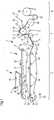
Die
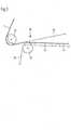
Alternativ zu der in
Die Pressenpartie
Diese Lösung hat den Vorteil, dass die Qualität, z. Bsp. die Helligkeit, der Deckelage der mehrlagigen Faserstoffbahn
In einer nicht dargestellten Weiterbildung können die beiden Lagen
Den Formiereinheiten
In der Vorrichtung nach
Die Formiereinheiten
Direkt nach dem am gemeinsamen Gegenelement
Nach einem ersten Trocknungsschritt kann die Faserstoffbahn
Innerhalb der Schlaufe des Siebes
Die
Zur Verbesserung der Qualität, insbesondere der Formation und Spaltfestigkeit der höherwertigen Deckelage
Innerhalb der Schlaufe des permeablen Transferbandes
Innerhalb der Schlaufe des Siebes
In der
BezugszeichenlisteLIST OF REFERENCE NUMBERS
- 11
- Vorrichtung contraption
- 22
- erste Formiereinheit first forming unit
- 33
- zweite Formiereinheit second forming unit
- 44
- Stoffauflauf headbox
- 55
- Stoffauflauf headbox
- 66
- Siebpartie Wire section
- 77
- Pressenpartie press section
- 88th
- Trockenpartie drying section
- 99
- erste Lage der Faserstoffbahn first layer of the fibrous web
- 1010
- zweite Lage der Faserstoffbahn second layer of the fibrous web
- 1111
- Faserstoffbahn Fibrous web
- 1212
- vorletzter Pressnip penultimate press nip
- 1313
- letzter Pressnip last press nip
- 1414
- weiterer Pressnip further press nip
- 1515
- erstes Presselement first pressing element
- 1616
- zweites Presselement second pressing element
- 1717
- Gegenwalze backing roll
- 1818
- gemeinsames Gegenelement common counter element
- 1919
- Pressband press belt
- 2020
- Transferband transfer tape
- 2121
- Saugelement suction
- 2222
- Maschinenlaufrichtung Machine direction
- 2323
- Laufrichtung der ersten Formiereinheit Running direction of the first forming unit
- 2424
- Stützwalze supporting roll
- 2525
- Filzband Filzband
- 2626
- Filzband Filzband
- 2727
- Trockensieb dryer
- 2828
- Trockenzylinder drying cylinders
- 2929
- Saugumlenkwalze suction turning roll
- 3030
- Obersieb top wire
- 3131
- Stabilisatoren stabilizers
- 3232
- Saugwalze suction roll
- 3333
- Übernahmesaugwalze Übernahmesaugwalze
- 3434
- Übernahmestelle over location
- 3535
- Sieb der ersten Formiereinheit Sieve of the first forming unit
- 3636
- Sieb der zweiten Formiereinheit Sieve of the second forming unit
- 3737
- Vergautschungszone Vergautschungszone
- 3838
- Saugelemente suckers
ZITATE ENTHALTEN IN DER BESCHREIBUNG QUOTES INCLUDE IN THE DESCRIPTION
Diese Liste der vom Anmelder aufgeführten Dokumente wurde automatisiert erzeugt und ist ausschließlich zur besseren Information des Lesers aufgenommen. Die Liste ist nicht Bestandteil der deutschen Patent- bzw. Gebrauchsmusteranmeldung. Das DPMA übernimmt keinerlei Haftung für etwaige Fehler oder Auslassungen.This list of the documents listed by the applicant has been generated automatically and is included solely for the better information of the reader. The list is not part of the German patent or utility model application. The DPMA assumes no liability for any errors or omissions.
Zitierte PatentliteraturCited patent literature
- DE 102014210879 A1[0003]DE 102014210879 A1[0003]
- WO 01/18309 A1[0004]WO 01/18309 A1[0004]
Claims (14)
Translated fromGermanPriority Applications (4)
| Application Number | Priority Date | Filing Date | Title |
|---|---|---|---|
| DE102016204969.0ADE102016204969A1 (en) | 2016-03-24 | 2016-03-24 | Apparatus and method for producing a fibrous web in a paper machine |
| EP17712495.5AEP3433420B1 (en) | 2016-03-24 | 2017-03-21 | Device and method for producing a multiple-layer fibrous web |
| CN201780018567.3ACN108884633B (en) | 2016-03-24 | 2017-03-21 | Device and method for producing a multi-layered fibrous web |
| PCT/EP2017/056721WO2017162685A1 (en) | 2016-03-24 | 2017-03-21 | Device and method for producing a multiple-layer fibrous web |
Applications Claiming Priority (1)
| Application Number | Priority Date | Filing Date | Title |
|---|---|---|---|
| DE102016204969.0ADE102016204969A1 (en) | 2016-03-24 | 2016-03-24 | Apparatus and method for producing a fibrous web in a paper machine |
Publications (1)
| Publication Number | Publication Date |
|---|---|
| DE102016204969A1true DE102016204969A1 (en) | 2017-05-18 |
Family
ID=58640071
Family Applications (1)
| Application Number | Title | Priority Date | Filing Date |
|---|---|---|---|
| DE102016204969.0ACeasedDE102016204969A1 (en) | 2016-03-24 | 2016-03-24 | Apparatus and method for producing a fibrous web in a paper machine |
Country Status (1)
| Country | Link |
|---|---|
| DE (1) | DE102016204969A1 (en) |
Cited By (7)
| Publication number | Priority date | Publication date | Assignee | Title |
|---|---|---|---|---|
| DE102016218101A1 (en)* | 2016-09-21 | 2017-10-05 | Voith Patent Gmbh | Apparatus and method for producing a fibrous web in a paper machine |
| DE102016218100A1 (en)* | 2016-09-21 | 2017-10-05 | Voith Patent Gmbh | Device for producing a fibrous web in a paper machine |
| DE102019121068A1 (en) | 2019-08-05 | 2020-07-02 | Voith Patent Gmbh | Device for producing a multi-layer fibrous web |
| DE102019121067A1 (en) | 2019-08-05 | 2020-07-02 | Voith Patent Gmbh | Device for producing a multi-layer fibrous web |
| DE102019125911A1 (en)* | 2019-09-26 | 2020-11-26 | Voith Patent Gmbh | Machine and method for producing a decorative base paper web |
| DE102019125929A1 (en)* | 2019-09-26 | 2021-04-01 | Voith Patent Gmbh | Machine and method for producing a decorative base paper web |
| AT526229A4 (en)* | 2023-05-05 | 2024-01-15 | Andritz Ag Maschf | MACHINE AND METHOD FOR PRODUCING A FIBROUS WEB |
Citations (4)
| Publication number | Priority date | Publication date | Assignee | Title |
|---|---|---|---|---|
| WO2001018309A1 (en) | 1999-09-07 | 2001-03-15 | Metso Paper Karlstad Aktiebolag | Method and paper machine for production of a liner |
| DE102010031440A1 (en)* | 2010-07-16 | 2012-01-19 | Voith Patent Gmbh | Method for manufacturing fibrous material web, particularly paper, cardboard or tissue web, involves providing upper side in press gap, where upper side is smoothed than lower side |
| DE112009002741T5 (en)* | 2008-08-22 | 2013-03-14 | Metso Paper, Inc. | board machine |
| DE102014210879A1 (en) | 2014-06-06 | 2015-12-17 | Voith Patent Gmbh | Process for the production of multi-ply packaging paper, paper machine for the production of multi-ply packaging paper and multi-ply packaging paper produced by this process |
- 2016
- 2016-03-24DEDE102016204969.0Apatent/DE102016204969A1/ennot_activeCeased
Patent Citations (5)
| Publication number | Priority date | Publication date | Assignee | Title |
|---|---|---|---|---|
| WO2001018309A1 (en) | 1999-09-07 | 2001-03-15 | Metso Paper Karlstad Aktiebolag | Method and paper machine for production of a liner |
| DE60027739T2 (en)* | 1999-09-07 | 2007-04-05 | Metso Paper, Inc. | METHOD AND PAPER MACHINE FOR MANUFACTURING CARTON WITH AT LEAST TWO LAYERS |
| DE112009002741T5 (en)* | 2008-08-22 | 2013-03-14 | Metso Paper, Inc. | board machine |
| DE102010031440A1 (en)* | 2010-07-16 | 2012-01-19 | Voith Patent Gmbh | Method for manufacturing fibrous material web, particularly paper, cardboard or tissue web, involves providing upper side in press gap, where upper side is smoothed than lower side |
| DE102014210879A1 (en) | 2014-06-06 | 2015-12-17 | Voith Patent Gmbh | Process for the production of multi-ply packaging paper, paper machine for the production of multi-ply packaging paper and multi-ply packaging paper produced by this process |
Cited By (8)
| Publication number | Priority date | Publication date | Assignee | Title |
|---|---|---|---|---|
| DE102016218101A1 (en)* | 2016-09-21 | 2017-10-05 | Voith Patent Gmbh | Apparatus and method for producing a fibrous web in a paper machine |
| DE102016218100A1 (en)* | 2016-09-21 | 2017-10-05 | Voith Patent Gmbh | Device for producing a fibrous web in a paper machine |
| DE102019121068A1 (en) | 2019-08-05 | 2020-07-02 | Voith Patent Gmbh | Device for producing a multi-layer fibrous web |
| DE102019121067A1 (en) | 2019-08-05 | 2020-07-02 | Voith Patent Gmbh | Device for producing a multi-layer fibrous web |
| DE102019125911A1 (en)* | 2019-09-26 | 2020-11-26 | Voith Patent Gmbh | Machine and method for producing a decorative base paper web |
| DE102019125929A1 (en)* | 2019-09-26 | 2021-04-01 | Voith Patent Gmbh | Machine and method for producing a decorative base paper web |
| AT526229A4 (en)* | 2023-05-05 | 2024-01-15 | Andritz Ag Maschf | MACHINE AND METHOD FOR PRODUCING A FIBROUS WEB |
| AT526229B1 (en)* | 2023-05-05 | 2024-01-15 | Andritz Ag Maschf | MACHINE AND METHOD FOR PRODUCING A FIBROUS WEB |
Similar Documents
| Publication | Publication Date | Title |
|---|---|---|
| DE102016204969A1 (en) | Apparatus and method for producing a fibrous web in a paper machine | |
| EP2576895B1 (en) | Machine, method and use of the machine for producing a paper web, in particular a sack paper web | |
| DE102018119686A1 (en) | paper machine | |
| AT511561A2 (en) | Method and production line for producing a multilayer material web | |
| DE102011077523A1 (en) | Machine for producing one-sided smooth fibrous web e.g. one-sided smooth paper, has web travel path that is arranged in wire section so that underside of web comes in contact with waterproof tape and surface of smoothing cylinder | |
| EP3622112A1 (en) | Device and method for producing a fibrous web | |
| WO2012007297A1 (en) | Machine having a press section and method for producing a fiber web | |
| EP3358074B1 (en) | Method for making a multilayer fibrous web with white surface layer | |
| DE102016217726A1 (en) | Apparatus and method for producing a fibrous web in a paper machine | |
| DE102017110032A1 (en) | Apparatus and method for producing a fibrous web | |
| EP2235256A1 (en) | Device for producing and/or processing a fiber material web | |
| DE102016218101A1 (en) | Apparatus and method for producing a fibrous web in a paper machine | |
| EP3433420B1 (en) | Device and method for producing a multiple-layer fibrous web | |
| DE202017106978U1 (en) | Wire section, in particular a converted wire section | |
| DE102011005747A1 (en) | Sheet binding device | |
| DE60316971T2 (en) | METHOD FOR THE PRODUCTION OF PAPER AND MACHINE FOR THE MANUFACTURE OF PAPER | |
| DE60119366T2 (en) | PRESS PARTY FOR A CARDBOARD MACHINE PRESENTED WITH A PRESS-SPRINT AND METHOD FOR DRAINING A PAPER TRACK IN SUCH A PRESS PARTY | |
| DE102014210883A1 (en) | Device for producing a fibrous web | |
| DE102017111869A1 (en) | Apparatus and method for producing a fibrous web | |
| EP1778914A1 (en) | Paper machine comprising a single-nip press | |
| DE102020101913A1 (en) | Device for the production of White Top Kraftliner and use of this device for the production of White Top Kraftliner | |
| DE102019121066A1 (en) | Device for the production of a multi-layer fibrous web | |
| DE102019121067A1 (en) | Device for producing a multi-layer fibrous web | |
| WO2016083172A1 (en) | Device for producing a fibrous web | |
| DE102019125929A1 (en) | Machine and method for producing a decorative base paper web |
Legal Events
| Date | Code | Title | Description |
|---|---|---|---|
| R012 | Request for examination validly filed | ||
| R230 | Request for early publication | ||
| R002 | Refusal decision in examination/registration proceedings | ||
| R003 | Refusal decision now final |