Movatterモバイル変換


[0]ホーム

URL:


DE102016204451A1 - Distillation device with a distillation module for a membrane distillation - Google Patents

Distillation device with a distillation module for a membrane distillation
Download PDF

Info

Publication number
DE102016204451A1
DE102016204451A1DE102016204451.6ADE102016204451ADE102016204451A1DE 102016204451 A1DE102016204451 A1DE 102016204451A1DE 102016204451 ADE102016204451 ADE 102016204451ADE 102016204451 A1DE102016204451 A1DE 102016204451A1
Authority
DE
Germany
Prior art keywords
evaporator
channel
inlet
condenser
outlet
Prior art date
Legal status (The legal status is an assumption and is not a legal conclusion. Google has not performed a legal analysis and makes no representation as to the accuracy of the status listed.)
Withdrawn
Application number
DE102016204451.6A
Other languages
German (de)
Inventor
Andrea Hagedorn
Joachim Koschikowski
Thomas Mann
Daniel Winter
Dennis Maucher
Current Assignee (The listed assignees may be inaccurate. Google has not performed a legal analysis and makes no representation or warranty as to the accuracy of the list.)
Mahle International GmbH
Fraunhofer Gesellschaft zur Foerderung der Angewandten Forschung eV
Original Assignee
Mahle International GmbH
Fraunhofer Gesellschaft zur Foerderung der Angewandten Forschung eV
Priority date (The priority date is an assumption and is not a legal conclusion. Google has not performed a legal analysis and makes no representation as to the accuracy of the date listed.)
Filing date
Publication date
Application filed by Mahle International GmbH, Fraunhofer Gesellschaft zur Foerderung der Angewandten Forschung eVfiledCriticalMahle International GmbH
Priority to DE102016204451.6ApriorityCriticalpatent/DE102016204451A1/en
Publication of DE102016204451A1publicationCriticalpatent/DE102016204451A1/en
Withdrawnlegal-statusCriticalCurrent

Links

Images

Classifications

Landscapes

Abstract

Translated fromGerman

Die vorliegende Erfindung betrifft ein Destillationsmodul (2) für eine Membrandestillation, umfassend einen Verdampfereinlasskanal (25) mit einer Verdampfereinlassöffnung (26), mehrere Verdampferauslasskanäle (27) mit jeweils einer Verdampferauslassöffnung (32), mehrere Kondensatoreinlasskanäle (30) mit jeweils einer Kondensatoreinlassöffnung (33), mehrere Kondensatorauslasskanäle (31) mit jeweils einer Kondensatorauslassöffnung (34), mehrere spiralförmig gewickelte Destillationsmembranen (35), die mehrere Verdampferkanalschichten (37), mehrere Kondensatorkanalschichten (38) und mehrere dazwischen angeordnete Membranschichten (39) ausbilden, und ein Gehäuse (21), das einen ersten Endboden (23) und einen zweiten Endboden (24) aufweist. Die Verdampferkanalschichten (37) verbinden jeweils den Verdampfereinlasskanal (25) mit je einem Verdampferauslasskanal (27). Die Kondensatorkanalschichten (38) verbinden jeweils einen Kondensatoreinlasskanal (30) mit je einem Kondensatorauslasskanal (31). Der erste Endboden (23) weist einen mit der Verdampfereinlassöffnung (26) verbundenen Verdampfereinlass (7) und einen mit den Kondensatoreinlassöffnungen (33) verbundenen Kondensatoreinlass (14) auf, während der zweite Endboden (24) einen mit den Verdampferauslassöffnungen (32) verbundenen Verdampferauslass (12) und einen mit den Kondensatorauslassöffnungen (34) verbundenen Kondensatorauslass (17) aufweist.The present invention relates to a distillation module (2) for a membrane distillation, comprising an evaporator inlet channel (25) with an evaporator inlet opening (26), a plurality of evaporator outlet channels (27) each having an evaporator outlet opening (32), a plurality of condenser inlet channels (30) each having a condenser inlet opening (33 ), a plurality of condenser outlet channels (31) each having a condenser outlet port (34), a plurality of spirally wound distillation membranes (35) forming a plurality of evaporator channel layers (37), a plurality of condenser channel layers (38) and a plurality of membrane layers (39) interposed therebetween, and a housing (21 ) having a first end floor (23) and a second end floor (24). The evaporator channel layers (37) each connect the evaporator inlet channel (25) with one evaporator outlet channel (27). The condenser channel layers (38) each connect a condenser inlet channel (30), each with a condenser outlet channel (31). The first end floor (23) has an evaporator inlet (7) connected to the evaporator inlet opening (26) and a condenser inlet (14) connected to the condenser inlet openings (33), while the second end floor (24) has an evaporator outlet connected to the evaporator outlet openings (32) (12) and a capacitor outlet (17) connected to the condenser outlet openings (34).

Description

Translated fromGerman

Die vorliegende Erfindung betrifft ein Destillationsmodul für eine Membrandestillation. Die Erfindung betrifft außerdem eine Destillationseinrichtung, insbesondere zur Mehrwasserentsalzung, die mit mindestens einem derartigen Destillationsmodul ausgestattet ist.The present invention relates to a distillation module for a membrane distillation. The invention also relates to a distillation device, in particular for multi-desalination, which is equipped with at least one such distillation module.

Bei einer Membrandestillation handelt es sich um ein thermisch getriebenes Separationsverfahren, bei dem die Separation aufgrund eines Phasenwechsels erfolgt. Eine hydrophobe Membran stellt hierbei eine Barriere für die flüssige Phase, zum Beispiel Salzwasser, eines Fluidstroms dar. Die dampfförmige Phase, zum Beispiel Wasserdampf, kann jedoch durch die Poren der Membran permeieren. Die treibende Kraft für den Prozess bildet ein Partialdampfdruckgefälle, welches üblicherweise durch eine Temperaturdifferenz hervorgerufen wird. Die Membrandestillation kann beispielsweise zur Gewinnung von Süßwasser, insbesondere Trinkwasser oder Brauchwasser, aus Salzwasser, üblicherweise Meerwasser, genutzt werden, zum Beispiel auf einem Schiff oder in einer stationären Anlage auf dem Land. Eine hierbei zum Einsatz kommende Destillationsmembran zeichnet sich durch eine hydrophobe und dampfdurchlässige Membranschicht aus, die eine Verdampferkanalschicht von einer Kondensatorkanalschicht trennt. Über die Verdampferkanalschicht wird eine Verdampferflüssigkeit bzw. Speiseflüssigkeit zugeführt, deren Flüssigkeitsgehalt durch Verdampfung reduziert werden soll. Im Beispiel der Meerwasserentsalzung wird als Speiseflüssigkeit bzw. Verdampferflüssigkeit Salzwasser verwendet. Durch Verdampfen von Wasser reduziert sich der Wasseranteil im Salzwasser, wodurch der Salzanteil im Salzwasser zunimmt. In der Kondensatorkanalschicht wird dagegen eine Kondensatorflüssigkeit, die kurz auch als Kondensat bezeichnet werden kann, oder Destillatflüssigkeit geführt, die kurz auch als Destillat bezeichnet werden kann.Membrane distillation is a thermally driven separation process in which the separation is due to a phase change. A hydrophobic membrane in this case represents a barrier to the liquid phase, for example salt water, of a fluid stream. However, the vapor phase, for example water vapor, can permeate through the pores of the membrane. The driving force for the process is a partial vapor pressure gradient, which is usually caused by a temperature difference. Membrane distillation can be used, for example, to obtain fresh water, in particular drinking water or service water, from salt water, usually seawater, for example on a ship or in a stationary facility in the countryside. A distillation membrane used here is characterized by a hydrophobic and vapor-permeable membrane layer which separates an evaporator channel layer from a condenser channel layer. Via the evaporator channel layer, an evaporator liquid or feed liquid is fed, the liquid content of which is to be reduced by evaporation. In the example of seawater desalination salt water is used as the feed liquid or evaporator liquid. Evaporation of water reduces the amount of water in salt water, which increases the salt content in salt water. In the condenser channel layer, however, a condenser liquid, which can also be referred to as condensate for short, or distillate liquid is passed, which can be briefly referred to as distillate.

Das Destillat wird durch den Flüssigkeitsdampf, der aus der Verdampferkanalschicht durch die Membranschicht hindurch in die Kondensatorkanalschicht gelangt, durch Kondensation dieses Flüssigkeitsdampfs angereichert. Dieser Flüssigkeitsdampf repräsentiert dabei ein Permeat, das am Destillat kondensiert und dadurch das Destillat vermehrt. Im Beispiel der Meerwasserentsalzung ist das Destillat Süßwasser, das durch den daran kondensierenden Wasserdampf des Salzwassers vermehrt wird. Die aufkonzentrierte Speiseflüssigkeit tritt als Retentatflüssigkeit oder kurz als Retentat aus der Verdampferkanalschicht aus. Im Beispiel der Meerwasserentsalzung ist das Retentat durch Salzwasser gebildet, das eine erhöhte Salzkonzentration besitzt.The distillate is enriched by condensation of this liquid vapor through the liquid vapor which passes from the evaporator channel layer through the membrane layer into the condenser channel layer. This liquid vapor represents a permeate which condenses on the distillate and thereby increases the distillate. In the example of seawater desalination, the distillate is fresh water, which is increased by the condensing water vapor of the salt water. The concentrated feed liquid exits as a retentate liquid or briefly as a retentate from the evaporator channel layer. In the example of seawater desalination, the retentate is formed by salt water, which has an increased salt concentration.

In der Praxis kommen im Wesentlichen vier verschiedene Membrandestillationsverfahren, kurz MD-Verfahren, zum Einsatz. Bei einem Direct Contact MD-Verfahren (DCMD) sind beide Seiten der Membran direkt mit Flüssigkeit beaufschlagt. Auf der Verdampferseite befindet sich die heiße Speiseflüssigkeit, während sich permeatseitig gekühltes Permeat bzw. Kondensationsflüssigkeit befindet. Die Kondensation des durch die Membran hindurch permeierenden Dampfes findet direkt in der flüssigen Phase an der Membrangrenzschicht statt. Beim Air Gap MD-Verfahren (AGMD) entspricht der Aufbau des Verdampferkanals dem des DCMD-Verfahrens, während der Permeatkanal oder Kondensatorkanal zwischen der Permeatseite der Membran und der gekühlten Wandung liegt und mit Luft gefüllt ist. Beim Sweeping Gas MD-Verfahren (SWGMD) wird ein Kanalaufbau mit freiem Spalt auf der Permeatseite verwendet, was im Wesentlichen dem Aufbau des AGMD-Verfahrens entspricht. Allerdings wird beim SWGMD-Verfahren dieser Spalt mit einem Gas gespült. Die Kondensation des Dampfes findet dann außerhalb des MD-Moduls in einem separaten Kondensator statt. Beim Vacuum MD-Verfahren (VMD) wird ebenfalls ein Kanalaufbau mit Luftspalt verwendet, wobei der durch die Membran permiierte Dampf über einen Unterdruck aus dem Permeatkanal abgezogen wird und dann wie beim SWGMD-Verfahren außerhalb des MD-Moduls kondensiert wird.Essentially, four different membrane distillation processes, or MD processes for short, are used in practice. In a Direct Contact MD (DCMD) process, both sides of the membrane are directly exposed to liquid. On the evaporator side is the hot feed liquid, while permeate side is cooled permeate or condensation liquid. The condensation of the vapor permeating through the membrane takes place directly in the liquid phase at the membrane boundary layer. In the Air Gap MD method (AGMD), the structure of the evaporator channel corresponds to that of the DCMD method, while the permeate channel or condenser channel lies between the permeate side of the membrane and the cooled wall and is filled with air. In the Sweeping Gas MD (SWGMD) process, a permeated-side free-gap channel design is used, which essentially corresponds to the design of the AGMD method. However, in the SWGMD process, this gap is purged with a gas. The condensation of the steam then takes place outside the MD module in a separate condenser. The Vacuum MD (VMD) process also uses an air gap channel design whereby the vapor permeated through the membrane is withdrawn from the permeate channel via a vacuum and then condensed outside the MD module as in the SWGMD process.

Eine Destillationseinrichtung, die sich insbesondere zur Meerwasserentsalzung eignet, kann mit mindestens einem Destillationsmodul ausgestattet sein, das die erforderlichen Anschlüsse zum Zuführen und Abführen der unterschiedlichen Flüssigkeiten aufweist.A distillation device, which is particularly suitable for seawater desalination, can be equipped with at least one distillation module having the necessary connections for supplying and discharging the different liquids.

Aus derDE 10 2004 013 647 A1 ist ein Destillationsmodul bekannt, bei dem eine einzige Destillationsmembran spiralförmig um ein Zentrum gewickelt ist, die eine Verdampferkanalschicht, eine Kondensatorkanalschicht und eine zwischen der Verdampferkanalschicht und der Kondensatorkanalschicht angeordnete hydrophobe Membranschicht aufweist. Das bekannte Destillationsmodul besitzt einen Verdampfereinlass, über den die Speiseflüssigkeit zugeführt wird. Ferner ist ein Retentatauslass vorgesehen, über den die aufkonzentrierte Speiseflüssigkeit abgeführt werden kann. Schließlich sind zwei Permeatauslässe vorgesehen, nämlich ein erster Permeatauslass für dampfförmiges Permeat und ein zweiter Permeatauslass für flüssiges Permeat. Ein Einlass zum Zuführen von Kondensatflüssigkeit ist nicht vorgesehen.From the DE 10 2004 013 647 A1 For example, a distillation module is known in which a single distillation membrane is spirally wound around a center having an evaporator channel layer, a capacitor channel layer, and a hydrophobic membrane layer disposed between the evaporator channel layer and the capacitor channel layer. The known distillation module has an evaporator inlet, via which the feed liquid is supplied. Furthermore, a retentate outlet is provided, via which the concentrated feed liquid can be removed. Finally, two permeate outlets are provided, namely a first permeate outlet for vaporous permeate and a second permeate outlet for liquid permeate. An inlet for supplying condensate liquid is not provided.

Auch dieDE 10 2004 040 950 A1 zeigt ein Destillationsmodul, bei dem nur ein Speiseflüssigkeitseinlass, ein Permeatauslass und ein Retentatauslass vorgesehen sind. Ein Einlass für Kondensatflüssigkeit fehlt auch hier. In diesem Destillationsmodul ist wieder eine einzige Destillationsmembran spiralförmig um ein Zentrum gewickelt, wobei die Destillationsmembran zusätzlich eine Dampfkanalschicht enthält, die durch die Membranschicht von der Kondensatorkanalschicht getrennt ist. Innerhalb der spiralförmigen Wicklung der Destillationsmembran endet die Verdampferkanalschicht und ist mit dem innenliegenden Ende der Kondensatorkanalschicht verbunden, so dass bei diesem Beispiel die Speiseflüssigkeit zum Kühlen und zum Heizen dient. Die Dampfkanalschicht dient zum Kondensieren des Permeats und ist dementsprechend an den Permeatauslass oder Destillatauslass angeschlossen.Also the DE 10 2004 040 950 A1 shows a distillation module in which only a feed liquid inlet, a permeate outlet and a retentate outlet are provided. An inlet for condensate liquid is also missing here. In this distillation module is again a single Spiral distillation membrane wrapped around a center, wherein the distillation membrane additionally contains a vapor channel layer which is separated by the membrane layer of the condenser channel layer. Within the spiral winding of the distillation membrane, the evaporator channel layer terminates and is connected to the inner end of the condenser channel layer, so that in this example the feed liquid serves for cooling and heating. The vapor channel layer serves to condense the permeate and is accordingly connected to the permeate outlet or distillate outlet.

Aus derDE 40 08 066 C2 ist eine Destillationseinrichtung bekannt, die eine Verdampfungs- und Kondensationseinheit aufweist, in der eine Vielzahl von Rinnen zum Führen von Verdampferflüssigkeit und Kondensatorflüssigkeit angeordnet ist. Diese Einheit besitzt einen Zulauf für Verdampferflüssigkeit (Speiseflüssigkeit), einen Ablauf für Verdampferflüssigkeit (Retentat), einen Zulauf für Kondensatorflüssigkeit (Destillat) und einen Ablauf für Kondensatorflüssigkeit (Destillat). Das Destillat wird bei der bekannten Vorrichtung somit zum Kühlen genutzt.From theDE 40 08 066 C2 For example, a distillation apparatus is known, which has an evaporation and condensation unit in which a plurality of channels for guiding evaporator liquid and condenser liquid is arranged. This unit has an inlet for evaporator liquid (feed liquid), a drain for evaporator liquid (retentate), a feed for condenser liquid (distillate) and a drain for condenser liquid (distillate). The distillate is thus used in the known device for cooling.

Aus derEP 1 029 583 A1 ist, derDE 203 03 013 U1 und derDE 15 17 915 A ist jeweils ein Destillationsmodul bekannt, bei dem mehreren Destillationsmembranen spiralförmig um ein Zentrum gewickelt sind, so dass mehrere parallel durchströmbare Verdampferkanalschichten, mehrere parallel durchströmbare Kondensatorkanalschichten und mehrere hydrophobe Membranschichten vorhanden sind, die jeweils zwischen einer Verdampferkanalschicht und einer Kondensatorkanalschicht angeordnet sind. Auch bei diesen Destillationsmodulen sind jeweils nur drei Anschlüsse vorgesehen, nämlich ein Speiseflüssigkeitseinlass, ein Retentatauslass und ein Permeatauslass. Ein Einlass für Kondensatorflüssigkeit fehlt.From the EP 1 029 583 A1 is the DE 203 03 013 U1 and theDE 15 17 915 A In each case, a distillation module is known in which a plurality of distillation membranes are spirally wound around a center, so that a plurality of parallel-flow evaporator channel layers, a plurality of parallel-flowable Kondensatorkanalschichten and a plurality of hydrophobic membrane layers are provided, which are each arranged between an evaporator channel layer and a Kondensatorkanalschicht. Also in these distillation modules only three ports are provided, namely a feed liquid inlet, a retentate outlet and a permeate outlet. An inlet for condenser liquid is missing.

Die vorliegende Erfindung beschäftigt sich mit dem Problem, für ein Destillationsmodul der eingangs genannten Art bzw. für eine damit ausgestattete Destillationseinrichtung eine verbesserte oder zumindest eine andere Ausführungsform anzugeben, die sich insbesondere durch einen kompakten Aufbau auszeichnet.The present invention is concerned with the problem of providing for a distillation module of the type mentioned above or for a distillation device equipped therewith an improved or at least another embodiment, which is characterized in particular by a compact structure.

Dieses Problem wird erfindungsgemäß durch den Gegenstand des unabhängigen Anspruchs gelöst. Vorteilhafte Ausführungsformen sind Gegenstand der abhängigen Ansprüche.This problem is solved according to the invention by the subject matter of the independent claim. Advantageous embodiments are the subject of the dependent claims.

Die Erfindung beruht auf dem allgemeinen Gedanken, das Destillationsmodul mit mehreren spiralförmig um ein Zentrum gewickelten Destillationsmembranen auszustatten, um mehrere Verdampferkanalschichten, mehrere Kondensatorkanalschichten und mehrere, jeweils zwischen einer Verdampferkanalschicht und einer Kondensatorkanalschicht angeordneten Membranschichten auszubilden. Die Membranschichten bestehen dabei aus einem hydrophoben Membranmaterial. In der Folge ist das Membranmaterial und somit die daraus hergestellte Membranschicht für die Kondensatorflüssigkeit und für die Verdampferflüssigkeit weitgehend undurchlässig, während sie für Dampf der Verdampferflüssigkeit durchlässig ist. Das Membranmaterial ist daher insbesondere semipermeabel. Ferner wird vorgeschlagen, das Destillationsmodul gehäuseseitig mit einem Verdampfereinlass zum Zuführen von Verdampferflüssigkeit, mit einem Kondensatoreinlass zum Zuführen von Kondensatorflüssigkeit, mit einem Verdampferauslass zum Abführen von Verdampferflüssigkeit und mit einem Kondensatorauslass zum Abführen von Kondensatorflüssigkeit auszustatten. Als Kondensatorflüssigkeit wird dabei das Permeat bzw. Kondensat oder Destillat verwendet, so dass sein Massestrom beim Durchströmen des Destillationsmoduls zunimmt, nämlich durch das Permeat, also den Flüssigkeitsdampf, der aus der Verdampferflüssigkeit austritt, die Membran durchtritt und an bzw. in der Kondensatorflüssigkeit kondensiert. Insbesondere lässt sich hierdurch eine effiziente Kühlung innerhalb des Destillationsmoduls auf der Kondensatorseite realisieren. Durch die Parallelschaltung mehrerer Flüssigkeitsströme lässt sich dabei eine hohe Effizienz bei kompakter Bauweise realisieren. Die kompakte Bauweise ist dabei außerdem für einen energieeffizienten Betrieb von Vorteil. Eine solche kompakte Bauweise kann bei reduziertem Raumangebot von Vorteil sein, z.B. auf einem Schiff.The invention is based on the general idea of equipping the distillation module with a plurality of distillation membranes spirally wound around a center to form a plurality of evaporator channel layers, a plurality of capacitor channel layers, and a plurality of membrane layers each disposed between an evaporator channel layer and a capacitor channel layer. The membrane layers consist of a hydrophobic membrane material. As a result, the membrane material, and thus the membrane layer made therefrom, is substantially impermeable to the condenser liquid and to the evaporator liquid, while it is permeable to vapor of the evaporator liquid. The membrane material is therefore in particular semipermeable. It is also proposed to provide the distillation module on the housing side with an evaporator inlet for supplying evaporator liquid, with a condenser inlet for supplying condenser liquid, with an evaporator outlet for discharging evaporator liquid and with a condenser outlet for discharging condenser liquid. As the condenser liquid while the permeate or condensate or distillate is used so that its mass flow increases as it flows through the distillation module, namely by the permeate, ie the liquid vapor exiting the evaporator liquid, the membrane passes and condenses on or in the condenser liquid. In particular, this makes it possible to realize efficient cooling within the distillation module on the condenser side. By connecting several liquid streams in parallel, high efficiency and compact design can be achieved. The compact design is also advantageous for energy-efficient operation. Such a compact construction may be advantageous in a reduced space, e.g. on a ship.

Im Einzelnen schlägt die Erfindung vor, innerhalb des Destillationsmoduls für sämtliche Destillationsmembranen zumindest einen Verdampfereinlasskanal vorzusehen, der mit einer oder mit mehreren oder mit allen Verdampferkanalschichten fluidisch verbunden ist. Ferner ist für jede Destillationsmembran ein Verdampferauslasskanal vorgesehen, der mit jeweils einer Verdampferkanalschicht fluidisch verbunden ist. Außerdem sind für die Destillationsmembranen jeweils ein Kondensatoreinlasskanal und ein Kondensatorauslasskanal vorgesehen, die an entgegengesetzten Enden mit der jeweiligen Kondensatorkanalschicht fluidisch verbunden sind. Der Verdampfereinlass des Gehäuses ist mit dem Verdampfereinlasskanal fluidisch verbunden, während der Verdampferauslass des Gehäuses mit den Verdampferauslasskanälen fluidisch verbunden ist. Ebenso ist der Kondensatoreinlass des Gehäuses mit den Kondensatoreinlasskanälen fluidisch verbunden, während der gehäuseseitige Kondensatorauslass mit den Kondensatorauslasskanälen fluidisch verbunden ist. Auf diese Weise besitzt das jeweilige Destillationsmodul gehäuseseitig im Extremfall genau bzw. nur vier Anschlüsse, während innerhalb des Destillationsmoduls entsprechend der jeweiligen Anzahl an Destillationsmembranen zumindest zwei Verdampferauslasskanäle, zumindest zwei Kondensatoreinlasskanäle und zumindest zwei Kondensatorauslasskanäle enthalten sind, um eine parallele Durchströmung der Verdampferkanalschichten und Kondensatorkanalschichten zu ermöglichen. Die gehäuseseitigen Anschlüsse sind dabei zweckmäßig an zwei axial voneinander beabstandeten Endböden des Gehäuses ausgebildet. Der erste Endboden weist den Verdampfereinlass und den Kondensatoreinlass auf und repräsentiert somit einen einlassseitigen Endboden. Der zweite Endboden weist den Verdampferauslass und den Kondensatorauslass auf und repräsentiert dadurch einen auslassseitigen Endboden.In detail, the invention proposes to provide within the distillation module for all distillation membranes at least one evaporator inlet channel, which is fluidically connected to one or more or all evaporator channel layers. Furthermore, an evaporator outlet channel is provided for each distillation membrane, which is fluidically connected to each one evaporator channel layer. In addition, a condenser inlet channel and a condenser outlet channel are respectively provided for the distillation membranes, which are fluidically connected at opposite ends to the respective condenser channel layer. The evaporator inlet of the housing is fluidically connected to the evaporator inlet channel, while the evaporator outlet of the housing is fluidically connected to the evaporator outlet channels. Likewise, the condenser inlet of the housing is fluidly connected to the condenser inlet channels, while the housing-side condenser outlet is fluidically connected to the condenser outlet channels. In this way, the respective distillation module has on the housing side in extreme cases exactly or only four ports, while within the distillation module corresponding to the respective number of distillation membranes at least two Evaporator outlet, at least two condenser inlet ducts and at least two Kondensatorenauslasskanäle are included to allow a parallel flow through the evaporator channel layers and capacitor channel layers. The housing-side connections are expediently formed on two axially spaced-apart end floors of the housing. The first end floor has the evaporator inlet and the condenser inlet and thus represents an inlet end end floor. The second end floor has the evaporator outlet and the condenser outlet and thereby represents an outlet end floor.

Vorteilhaft ist nur ein einziger, gemeinsamer Verdampfereinlasskanal vorgesehen, der vorzugsweise zentrisch oder zentral im Destillationsmodul angeordnet ist. Alternativ können auch mehrere Verdampfereinlasskanäle vorgesehen sein, insbesondere für jede Verdampferkanalschicht ein separater Verdampfereinlasskanal. Zweckmäßig sind die Verdampferauslasskanäle bezüglich des zentralen Verdampfereinlasskanals distal angeordnet. Die Kondensatoreinlasskanäle können zweckmäßig bezüglich des zentralen Verdampfereinlasskanals distal angeordnet sein. Im Unterschied dazu sind die Kondensatorauslasskanäle bezüglich des zentralen Verdampfereinlasskanals proximalen angeordnet. Ferner können die genannten Kanäle zweckmäßig jeweils geradlinig ausgestaltet und parallel zur Längsmittelachse des Destillationsmoduls ausgerichtet sein.Advantageously, only a single, common evaporator inlet channel is provided, which is preferably arranged centrally or centrally in the distillation module. Alternatively, a plurality of evaporator inlet channels may also be provided, in particular a separate evaporator inlet channel for each evaporator channel layer. Suitably, the evaporator outlet channels are arranged distally with respect to the central evaporator inlet channel. The condenser inlet passages may conveniently be located distally with respect to the central evaporator inlet passage. In contrast, the condenser outlet passages are proximal with respect to the central evaporator inlet passage. Furthermore, the said channels can expediently be embodied in a straight line in each case and aligned parallel to the longitudinal central axis of the distillation module.

Gemäß einer vorteilhaften Ausführungsform kann der erste Endboden einen ringförmigen Verteilerkanal enthalten, der den Kondensateinlass mit den Kondensateinlassöffnungen der Kondensateinlasskanäle fluidisch verbindet. Insoweit bildet der erste Endboden einen gehäuseseitigen Verteiler für das Kondensat. Die Integration des Verteilerkanals bzw. dieser Verteilerfunktion in den ersten Endboden vereinfachten den Aufbau und somit die Herstellung des Destillationsmoduls.According to an advantageous embodiment, the first end floor may include an annular distribution channel fluidly connecting the condensate inlet to the condensate inlet openings of the condensate inlet channels. In that regard, the first end floor forms a housing-side manifold for the condensate. The integration of the distribution channel or this distribution function in the first end floor simplified the construction and thus the production of the distillation module.

Zusätzlich oder alternativ kann am ersten Endboden der Verdampfereinlass zentrisch angeordnet sein, während der Kondensatoreinlass exzentrisch angeordnet ist. Hierdurch vereinfacht sich die fluidische Verbindung des Verdampfereinlasses mit dem ebenfalls zentral angeordneten gemeinsamen Verdampfereinlasskanal.Additionally or alternatively, the evaporator inlet can be arranged centrally on the first end floor, while the condenser inlet is arranged eccentrically. This simplifies the fluidic connection of the evaporator inlet with the also centrally arranged common evaporator inlet channel.

Bei einer anderen Ausführungsform kann der zweite Endboden einen ringförmigen Sammelkanal enthalten, der die Verdampferauslassöffnungen der Verdampferauslasskanäle mit dem Verdampferauslass des Gehäuses fluidisch verbindet. Hierdurch besitzt der zweite Endboden eine Sammlerfunktion für die Verdampferflüssigkeit. Durch die Integration des Sammelkanals bzw. dieser Sammlerfunktion in den zweiten Endboden vereinfacht sich die Herstellung des Destillationsmoduls.In another embodiment, the second end floor may include an annular collection channel fluidly connecting the evaporator outlet openings of the evaporator outlet channels to the evaporator outlet of the housing. As a result, the second end floor has a collector function for the evaporator liquid. The integration of the collecting channel or this collector function in the second end floor simplifies the production of the distillation module.

Zweckmäßig kann vorgesehen sein, dass am zweiten Endboden der Kondensatorauslass zentrisch angeordnet ist, während der Verdampferauslass exzentrisch angeordnet ist. Hierdurch verkürzen sich die Leitungsführungen innerhalb des zweiten Endbodens, was die Herstellung vereinfacht.Appropriately, it may be provided that the condenser outlet is arranged centrically on the second end base, while the evaporator outlet is arranged eccentrically. This shortens the cable guides within the second end floor, which simplifies the production.

Gemäß einer vorteilhaften Ausführungsform kann der Verdampfereinlasskanal durch einen Innenraum eines Verdampfereinlassrohrs gebildet sein, das an einem dem ersten Endboden zugewandten ersten Ende axial offen ist und dort die Verdampfereinlassöffnung bildet, wobei das Verdampfereinlassrohr an seinem dem zweiten Endboden zugewandten zweiten Ende axial verschlossen ist. Das Verdampfereinlassrohr weist außerdem für jede Verdampferkanalschicht zumindest eine radiale Verbindungsöffnung auf, durch die der durch den Innenraum des Verdampfereinlassrohrs gebildete Verdampfereinlasskanal mit der jeweiligen Verdampferkanalschicht fluidisch verbunden ist. Auf diese Weise wird eine besonders einfach realisierbare fluidische Verbindung zwischen dem Verdampfereinlasskanal und den Verdampferkanalschichten realisiert.According to an advantageous embodiment, the evaporator inlet channel may be formed by an interior of an evaporator inlet tube which is axially open at a first end facing the first end end and forms the evaporator inlet opening there, wherein the evaporator inlet tube is axially closed at its second end facing the second end. The evaporator inlet tube also has, for each evaporator channel layer, at least one radial connection opening, through which the evaporator inlet channel formed by the interior of the evaporator inlet tube is fluidically connected to the respective evaporator channel layer. In this way, a particularly easily realizable fluidic connection between the evaporator inlet channel and the evaporator channel layers is realized.

Bei einer anderen Ausführungsform kann der jeweilige Verdampferauslasskanal durch einen Innenraum eines Verdampferauslassrohrs gebildet sein, das an einem dem ersten Endboden zugewandten ersten Ende axial verschlossen ist, das an einem dem zweiten Endboden zugewandten zweiten Ende axial offen ist und dort die jeweilige Verdampferauslassöffnung bildet. Ferner weist das Verdampferauslassrohr für eine solche Verdampferkanalschicht zumindest eine radiale Verbindungsöffnung auf, durch die der durch den Innenraum des Verdampferauslassrohrs gebildete Verdampferauslasskanal mit der jeweiligen Verdampferkanalschicht fluidisch verbunden ist.In another embodiment, the respective evaporator outlet channel may be formed by an interior of an evaporator outlet tube which is axially closed at a first end facing the first end bottom, which is axially open at a second end facing the second end bottom and forms the respective evaporator outlet opening there. Furthermore, the evaporator outlet tube for such an evaporator channel layer has at least one radial connection opening, through which the evaporator outlet channel formed through the interior of the evaporator outlet tube is fluidically connected to the respective evaporator channel layer.

Zusätzlich oder alternativ kann der jeweilige Kondensatoreinlasskanal durch einen Innenraum eines Kondensatoreinlassrohrs gebildet sein, das an einem dem ersten Endboden zugewandten ersten Ende axial offen ist und die jeweilige Kondensatoreinlassöffnung bildet, das an einem dem zweiten Endboden zugewandten zweiten Ende axial verschlossen ist und das für eine solche Kondensatorkanalschicht wenigstens eine radiale Verbindungsöffnung aufweist, durch die der durch den Innenraum des Kondensatoreinlassrohrs gebildete Kondensatoreinlasskanal mit der jeweiligen Kondensatorkanalschicht fluidisch verbunden ist.Additionally or alternatively, the respective condenser inlet channel may be formed by an interior of a condenser inlet tube which is axially open at a first end facing the first end and forms the respective condenser inlet opening which is axially closed at a second end facing the second end base and which one for such Capacitor channel layer has at least one radial connection opening through which the capacitor inlet channel formed by the interior of the condenser inlet tube is fluidly connected to the respective condenser channel layer.

Zusätzlich oder alternativ kann der jeweilige Kondensatorauslasskanal durch einen Innenraum eines Kondensatoreinlassrohrs gebildet sein, das in einen dem ersten Endboden zugewandten ersten Ende axial verschlossen ist, das an einem dem zweiten Endboden zugewandten zweiten Ende axial offen ist und dort die jeweilige Kondensatorauslassöffnung bildet und das für eine solche Kondensatorkanalschicht wenigstens eine radiale Verbindungsöffnung aufweist, durch die der durch den Innenraum des Kondensatorauslassrohrs gebildeten Kondensatorauslasskanal mit der jeweiligen Kondensatorkanalschicht fluidisch verbunden ist.Additionally or alternatively, the respective Kondensatorauslasskanal through an interior a condenser inlet tube which is axially closed in a first end facing the first end bottom, which is axially open at a second end facing the second end bottom and there forms the respective Kondensatorauslassöffnung and which has at least one radial connection opening for such a capacitor channel layer through which the capacitor outlet channel formed by the interior of the condenser outlet tube is fluidically connected to the respective condenser channel layer.

Die vorstehend genannten Rohre, nämlich das Verdampfereinlassrohr, die Verdampferauslassrohre, die Kondensatoreinlassrohre und die Kondensatorauslassrohre bilden mit ihren radialen Verbindungsöffnungen vergleichsweise einfach realisierbare fluidische Kopplungen mit den zugehörigen Kanalschichten der Destillationsmembranen. Dementsprechend vereinfacht sich der Aufbau bzw. die Herstellung des Destillationsmoduls.The abovementioned tubes, namely the evaporator inlet tube, the evaporator outlet tubes, the condenser inlet tubes and the condenser outlet tubes, with their radial connection openings, form comparatively easily realizable fluidic couplings with the associated channel layers of the distillation membranes. Accordingly, the structure or the production of the distillation module is simplified.

Besonders vorteilhaft ist eine Ausführungsform, bei der je zwei in Umfangsrichtung benachbarte Membranschichten durch Längsabschnitte einer gemeinsamen Membranbahn aus hydrophobem Membranmaterial gebildet sind, wobei die beiden Längsabschnitte an ihren radial inneren Enden durch eine innere Schlaufe der Materialbahn und an ihren radial äußeren Enden durch eine äußere Schlaufe miteinander verbunden sind. Die Materialbahn ist dann in ihrer Bahnlängsrichtung als geschlossen umlaufende, quasi endlose Struktur ausgestaltet. Zwischen den Längsabschnitten ist eine innere Spacer-Materialbahn angeordnet, die zwischen den Längsabschnitten die jeweilige Verdampferkanalschicht oder die jeweilige Kondensatorkanalschicht definiert. Die Spacer-Materialbahn besitzt zweckmäßig eine Gitterstruktur oder Gewebestruktur, die von der jeweiligen Flüssigkeit leicht durchströmbar ist. Die innere Spacer-Materialbahn ist von der Membranbahn umlaufend geschlossen eingefasst.Particularly advantageous is an embodiment in which each two circumferentially adjacent membrane layers are formed by longitudinal sections of a common membrane membrane of hydrophobic membrane material, wherein the two longitudinal sections at their radially inner ends by an inner loop of the material web and at its radially outer ends by an outer loop connected to each other. The material web is then designed in its web longitudinal direction as a closed circumferential, virtually endless structure. Between the longitudinal sections, an inner spacer material web is arranged, which defines the respective evaporator channel layer or the respective condenser channel layer between the longitudinal sections. The spacer material web expediently has a lattice structure or tissue structure, which can easily be flowed through by the respective liquid. The inner spacer material web is enclosed circumferentially closed by the membrane web.

Gemäß einer vorteilhaften Weiterbildung definiert die jeweilige innere Spacer-Materialbahn eine Kondensatorkanalschicht und ragt radial innen durch die Verbindungsöffnung eines der Kondensatorauslassrohre in den jeweiligen Kondensatorauslasskanal hinein, während sie radial außen durch die Verbindungsöffnung eines solchen Kondensatoreinlassrohrs in den jeweiligen Kondensatoreinlasskanal hineinragt. Die innere Schlaufe umschlingt dann das jeweilige Kondensatorauslassrohr, während die äußere Schlaufe dann das jeweilige Kondensatoreinlassrohr umschlingt. Somit sind auch Kondensatoreinlassrohr und Kondensatorauslassrohr von der geschlossenen Membranbahn umschlossen bzw. eingefasst, wodurch die Gefahr von Leckagen erheblich reduziert ist.According to an advantageous development, the respective inner spacer material web defines a condenser channel layer and protrudes radially inward through the connection opening of one of the condenser outlet tubes into the respective condenser outlet channel, while it projects radially outward through the connection opening of such a condenser inlet tube into the respective condenser inlet channel. The inner loop then wraps around the respective Kondensatorauslassrohr while the outer loop then wraps around the respective condenser inlet tube. Thus, the condenser inlet pipe and the condenser outlet pipe are enclosed by the closed membrane web, whereby the risk of leaks is considerably reduced.

Gemäß einer anderen Weiterbildung kann zwischen zwei in der Umfangsrichtung benachbarten Membranbahnen eine äußere Spacer-Materialbahn angeordnet sein, die zwischen den einander zugewandten Längsabschnitten dieser beiden Membranbahnen die jeweilige Kondensatorkanalschicht oder die jeweilige Verdampferkanalschicht definiert.According to another development, an outer spacer material web may be arranged between two membrane webs adjacent in the circumferential direction, which defines the respective condenser channel layer or the respective evaporator channel layer between the mutually facing longitudinal sections of these two membrane webs.

Gemäß einer vorteilhaften Weiterbildung kann die jeweilige äußere Spacer-Materialbahn zweckmäßig eine Verdampferkanalschicht definieren und radial innen durch eine der Verbindungsöffnungen des Verdampfereinlassrohrs in den Verdampfereinlasskanal hineinragen, während sie radial außen durch die Verbindungsöffnung eines solchen Verdampferauslassrohrs in den Verdampferauslasskanal hineinragt. Auch hierdurch wird eine relativ einfache fluidische Verbindung geschaffen, die hinreichend dicht ist.According to an advantageous development, the respective outer spacer material web can expediently define an evaporator channel layer and protrude radially inward through one of the connection openings of the evaporator inlet tube into the evaporator inlet channel while it projects radially outward through the connection opening of such an evaporator outlet tube into the evaporator outlet channel. This also creates a relatively simple fluidic connection that is sufficiently dense.

Besonders vorteilhaft ist eine Ausführungsform, bei der innerhalb der jeweiligen Destillationsmembran die jeweilige Membranschicht einerseits dem in der Verdampferkanalschicht geführten Verdampfungsmittel und andererseits dem in der Kondensatorkanalschicht geführten Kondensationsmittel unmittelbar ausgesetzt ist. In diesem Fall ist das Destillationsmodul für ein DCMD-Verfahren vorgesehen. Es ist klar, dass bei anderen Ausführungsformen das Destillationsmodul auch für ein AGMD-Verfahren, für ein VMD-Verfahren oder für ein SWGMD-Verfahren vorgesehen sein kann.Particularly advantageous is an embodiment in which, within the respective distillation membrane, the respective membrane layer is on the one hand directly exposed to the evaporation medium carried in the evaporator channel layer and, on the other hand, to the condensing agent carried in the condenser channel layer. In this case, the distillation module is intended for a DCMD process. It will be understood that in other embodiments, the distillation module may also be provided for an AGMD process, for a VMD process, or for a SWGMD process.

Eine erfindungsgemäße Destillationseinrichtung, die sich vorzugsweise zur Meerwasserentsalzung eignet, umfasst mindestens ein Destillationsmodul der vorstehend beschriebenen Art. Ferner sind eine Verdampferzuführung zum Zuführen eines flüssigen Verdampfungsmittels, eine Kondensatorzuführung zum Zuführen eines flüssigen Kondensationsmittels, eine Verdampferabführung zum Abführen eines Retentats und eine Kondensatorabführung zum Abführen eines Permeats oder Kondensats oder Destillats vorgesehen. Innerhalb der Destillationseinrichtung können dabei mehrere Destillationsmodule parallel geschaltet sein und vorzugsweise auch parallel an die Verdampferzuführung, die Kondensatorzuführung, die Verdampferabführung und die Kondensatorabführung angeschlossen sein.A distillation apparatus according to the invention, which is preferably suitable for seawater desalination, comprises at least one distillation module of the type described above. Further, an evaporator feeder for supplying a liquid evaporant, a condenser feeder for supplying a liquid condensing agent, an evaporator effluent for discharging a retentate and a condenser effluent for discharging a Permeats or condensate or distillate provided. Within the distillation device, a plurality of distillation modules can be connected in parallel and preferably also connected in parallel to the evaporator feed, the condenser feed, the evaporator removal and the condenser removal.

Weitere wichtige Merkmale und Vorteile der Erfindung ergeben sich aus den Unteransprüchen, aus den Zeichnungen und aus der zugehörigen Figurenbeschreibung anhand der Zeichnungen.Other important features and advantages of the invention will become apparent from the dependent claims, from the drawings and from the associated figure description with reference to the drawings.

Es versteht sich, dass die vorstehend genannten und die nachstehend noch zu erläuternden Merkmale nicht nur in der jeweils angegebenen Kombination, sondern auch in anderen Kombinationen oder in Alleinstellung verwendbar sind, ohne den Rahmen der vorliegenden Erfindung zu verlassen.It is understood that the features mentioned above and those yet to be explained not only in the combination given, but also in other combinations or alone, without departing from the scope of the present invention.

Bevorzugte Ausführungsbeispiele der Erfindung sind in den Zeichnungen dargestellt und werden in der nachfolgenden Beschreibung näher erläutert, wobei sich gleiche Bezugszeichen auf gleiche oder ähnliche oder funktional gleiche Komponenten beziehen.Preferred embodiments of the invention are illustrated in the drawings and will be described in more detail in the following description, wherein like reference numerals refer to the same or similar or functionally identical components.

Es zeigen, jeweils schematisch,Show, in each case schematically,

1 eine schaltplanartige Prinzipdarstellung einer Destillationseinrichtung, 1 a circuit diagram-like schematic representation of a distillation device,

2 eine isometrische Ansicht eines Destillationsmoduls, 2 an isometric view of a distillation module,

3 ein Längsschnitt des Destillationsmoduls ohne Gehäusemantel, 3 a longitudinal section of the distillation module without housing shell,

4 ein Querschnitt des Destillationsmoduls gemäß Schnittlinien IV in3, 4 a cross section of the distillation module according to section lines IV in 3 .

5 ein Querschnitt des Destillationsmoduls entsprechend Schnittlinien V in3, 5 a cross section of the distillation module according to section lines V in 3 .

6 ein Querschnitt des Destillationsmoduls entsprechend Schnittlinien VI in3, 6 a cross section of the distillation module according to section lines VI in 3 .

7 eine vergrößerte und stark vereinfachte Detailansicht des Querschnitts aus4. 7 an enlarged and greatly simplified detail view of thecross section 4 ,

Entsprechend1 umfasst eine Destillationseinrichtung1, die vorzugsweise zur Meerwasserentsalzung verwendet und auf einem Wasserfahrzeug zum Einsatz kommen kann, zumindest ein Destillationsmodul2, in dem ein Verdampferpfad3 mittels einer hydrophoben Membranstruktur4 von einem Kondensatorpfad5 getrennt ist. Die Destillationseinrichtung1 weist außerdem eine Verdampferzuführung6 auf, mit der eine Verdampferflüssigkeit dem jeweiligen Destillationsmodul2 zuführbar ist. Die Verdampferzuführung6 ist hierzu an einen Verdampfereinlass7 des Destillationsmoduls2 angeschlossen. Zum Fördern der Verdampferflüssigkeit kann in der Verdampferzuführung6 eine Verdampfungsmittelpumpe8 angeordnet sein. In die Verdampferzuführung6 sind im gezeigten Beispiel ein erster Wärmeübertrager9 und ein zweiter Wärmeübertrager10 eingebunden, über die der Verdampferflüssigkeit Wärme zugeführt werden kann. Eine Verdampferabführung11 ist an einen Verdampferauslass12 des Destillationsmoduls2 angeschlossen und führt die Verdampferflüssigkeit ab, die an dieser Stelle auch als Retentat bezeichnet werden kann.Corresponding 1 comprises a distillation device 1 , which is preferably used for seawater desalination and can be used on a watercraft, at least onedistillation module 2 in which anevaporator path 3 by means of ahydrophobic membrane structure 4 from acapacitor path 5 is disconnected. The distillation device 1 also has anevaporator feed 6 on, with an evaporator liquid therespective distillation module 2 can be fed. Theevaporator feed 6 is this to anevaporator inlet 7 of thedistillation module 2 connected. For conveying the evaporator liquid can in theevaporator feed 6 an evaporative pump 8th be arranged. In theevaporator feed 6 are in the example shown, afirst heat exchanger 9 and asecond heat exchanger 10 integrated, via which the evaporator liquid heat can be supplied. Anevaporator discharge 11 is to anevaporator outlet 12 of thedistillation module 2 connected and performs the evaporator liquid, which can also be referred to as retentate at this point.

Die Destillationseinrichtung1 weist außerdem eine Kondensatorzuführung13 auf, die an einen Kondensatoreinlass14 des Destillationsmoduls2 angeschlossen ist und die zum Zuführen einer Kondensationsflüssigkeit dient. In der Kondensatorzuführung13 kann zum Antreiben der Kondensationsflüssigkeit eine Kondensationsmittelpumpe15 angeordnet sein. Ferner ist eine Kondensatabführung16 vorgesehen, die an einem Kondensatauslass17 des Destillationsmoduls2 angeschlossen ist und die zum Abführen der Kondensationsflüssigkeit dient.The distillation device 1 also has acapacitor feeder 13 on, attached to acondenser inlet 14 of thedistillation module 2 is connected and which serves to supply a condensation liquid. In thecondenser feeder 13 For driving the condensation liquid, a condensingagent pump 15 be arranged. Furthermore, acondensate drainage 16 provided at acondensate outlet 17 of thedistillation module 2 is connected and which serves to dissipate the condensation liquid.

Die Kondensationsflüssigkeit kann ab dieser Stelle auch als Permeat oder Kondensat oder Destillat bezeichnet werden. Die Kondensatorabführung16 ist in den ersten Wärmeübertrager9 eingebunden, wodurch eine Wärmerückgewinnung realisierbar ist. Die Kondensatorabführung16 endet an einem Verteiler18, von dem die Kondensatorzuführung13 ausgeht und von dem eine Destillatleitung19 ausgeht, die beispielsweise zu einem Destillattank führen kann. Der Verteiler18 steuert die Aufteilung des von der Kondensatorabführung16 zugeführten Destillatstroms auf die Destillatleitung19 und die Kondensatorzuführung13.The condensation liquid can be referred to from this point as permeate or condensate or distillate. Thecapacitor discharge 16 is in thefirst heat exchanger 9 integrated, whereby a heat recovery can be realized. Thecapacitor discharge 16 ends at adistributor 18 from which thecondenser feeder 13 goes out and from which adistillate line 19 goes out, for example, can lead to a distillate tank. Thedistributor 18 controls the division of thecapacitor discharge 16 supplied distillate stream on thedistillate line 19 and thecondenser feeder 13 ,

Der zweite Wärmeübertrager10 ist auf geeignete Weise in einen Heizkreis20 eingebunden, der grundsätzlich beliebiger Natur sein kann. Sofern die Destillationseinrichtung1 auf einem Schiff zum Einsatz kommt, kann der Heizkreis20 durch einen Zweig eines Kühlkreises eines Antriebsaggregats des Schiffs gebildet sein.Thesecond heat exchanger 10 is suitably in aheating circuit 20 involved, which basically can be of any nature. Unless the distillation device 1 can be used on a ship, theheating circuit 20 be formed by a branch of a cooling circuit of a drive unit of the ship.

Entsprechend den27 umfasst das Destillationsmodul2 ein Gehäuse21, das einen zylindrischen Mantel22 und zwei axial voneinander abgewandte Endböden, nämlich einen ersten Endboden23 und einen zweiten Endboden24 aufweist. Der Gehäusemantel22 ist nur in2 dargestellt. Der erste Endboden24 ist nur in den3 und5 erkennbar. Der zweite Endboden24 ist in den2,3 und6 erkennbar.According to the 2 - 7 includes the distillation module 2 ahousing 21 that has acylindrical coat 22 and two end floors facing away from each other axially, namely afirst end floor 23 and asecond end floor 24 having. Thehousing jacket 22 is only in 2 shown. Thefirst end floor 24 is only in the 3 and 5 recognizable. Thesecond end floor 24 is in the 2 . 3 and 6 recognizable.

Entsprechend den37 weist das Destillationsmodul2 einen zentralen Verdampfereinlasskanal25 auf, der eine Verdampfereinlassöffnung26 besitzt. Ferner sind mehrere Verdampferauslasskanäle27 vorgesehen, die bezüglich des Verdampfereinlasskanals25 distal, also radial beabstandet angeordnet sind und die in der Umfangsrichtung gleichförmig verteilt angeordnet sind. Die Umfangsrichtung ist in den2 und46 durch einen Doppelpfeil angedeutet und mit28 bezeichnet. Die Umfangsrichtung28 bezieht sich dabei auf eine Längsmittelachse29 des Destillationsmoduls2.According to the 3 - 7 indicates the distillation module 2 a centralevaporator inlet channel 25 on, which has an evaporator inlet opening 26 has. Furthermore, severalevaporator outlet channels 27 provided with respect to theevaporator inlet channel 25 distally, so are arranged radially spaced and which are arranged uniformly distributed in the circumferential direction. The circumferential direction is in the 2 and 4 - 6 indicated by a double arrow and with 28 designated. Thecircumferential direction 28 refers to a longitudinalcentral axis 29 of thedistillation module 2 ,

Des Weiteren sind mehrere Kondensatoreinlasskanäle30 vorgesehen, die ebenfalls bezüglich der Längsmittelachse29 bzw. bezüglich des Verdampfereinlasskanals25 radial distal angeordnet und in der Umfangsrichtung28 gleichförmig verteilt angeordnet sind. Zweckmäßig wechseln sich radial außen am Destillationsmodul2 innerhalb des Gehäusemantels22 die Verdampferauslasskanäle27 und die Kondensatoreinlasskanäle30 in der Umfangsrichtung28 ab. Ferner weist das Destillationsmodul2 mehrere Kondensatorauslasskanäle31 auf, die bezüglich der Längsmittelachse29 proximal, also angenähert angeordnet und in der Umfangsrichtung28 verteilt angeordnet sind. Die Verdampferauslasskanäle27 weisen jeweils eine Verdampferauslassöffnung32 auf. Die Kondensatoreinlasskanäle30 weisen jeweils eine Kondensatoreinlassöffnung33 auf. Die Kondensatorauslasskanäle31 weisen jeweils eine Kondensatorauslassöffnung34 auf.Furthermore, there are severalcondenser inlet channels 30 provided, which also with respect to thelongitudinal center axis 29 or with respect to theevaporator inlet channel 25 arranged radially distally and in thecircumferential direction 28 are arranged uniformly distributed. Appropriately alternate radially outside of thedistillation module 2 inside thecasing 22 theevaporator outlet channels 27 and thecondenser inlet channels 30 in thecircumferential direction 28 from. Furthermore, thedistillation module 2 severalcondenser outlet channels 31 on, with respect to thelongitudinal center axis 29 proximal, so approximately arranged and in thecircumferential direction 28 are arranged distributed. Theevaporator outlet channels 27 each have an evaporator outlet opening 32 on. Thecondenser inlet channels 30 each have a condenser inlet opening 33 on. Thecondenser outlet channels 31 each have a Kondensatorauslassöffnung 34 on.

Das hier gezeigte Destillationsmodul2 weist außerdem mehrere Destillationsmembranen35 auf, die um die Längsmittelachse29 spiralförmig gewickelt sind. Die Destillationsmembranen35 erstrecken sich dabei in der Umfangsrichtung28 spiralförmig gewickelt um den zentralen Verdampfereinlasskanal25 und die dazu proximal angeordneten Kondensatorauslasskanäle39. Die spiralförmig aufgewickelten Destillationsmembranen35 bilden eine Wicklung36, die in4 vereinfacht angedeutet ist. Innerhalb dieser Wicklung36 bilden die Destillationsmembranen35 gemäß7 mehrere Verdampferkanalschichten37, mehrere Kondensatorkanalschichten38 und mehrere Membranschichten39 aus. Die jeweilige Membranschicht39 ist dabei jeweils zwischen einer Verdampferkanalschicht37 und einer Kondensatorkanalschicht38 angeordnet und besteht aus einem hydrophoben und semipermeablen Membranmaterial. In3 ist zur Veranschaulichung in der linken Hälfte eine Verdampferkanalschicht37 dargestellt, während in der rechte Hälfte eine Kondensatorkanalschicht38 dargestellt ist. Gemäß den3 und7 sind die Verdampferkanalschichten37 an ihrem inneren Ende mit dem Verdampfereinlasskanal25 fluidisch verbunden, während sie mit ihrem äußeren Ende mit jeweils einem Verdampferauslasskanal27 fluidisch verbunden sind. Die relativen Angaben „innen“ und „außen“ beziehen sich auf die radiale Position. Die Kondensatorkanalschichten38 sind jeweils mit ihrem inneren Ende mit je einem Kondensatorauslasskanal31 und mit ihrem äußeren Ende jeweils mit einem Kondensatoreinlasskanal30 fluidisch verbunden. Dementsprechend verbinden die Verdampferkanalschichten37 jeweils den zentralen, gemeinsamen Verdampfereinlasskanal25 mit einem der Verdampferauslasskanäle27. Die Kondensatorkanalschichten38 verbinden dabei jeweils einen der Kondensatoreinlasskanäle30 mit einem der Kondensatorauslasskanäle31.The distillation module shown here 2 also hasseveral distillation membranes 35 on, around the longitudinalcentral axis 29 are wound spirally. Thedistillation membranes 35 extend in thecircumferential direction 28 spirally wound around the centralevaporator inlet channel 25 and the proximal arrangedcondenser outlet channels 39 , The spirallywound distillation membranes 35 form a winding 36 , in the 4 is indicated in simplified. Within this winding 36 form thedistillation membranes 35 according to 7 several evaporator channel layers 37 , several capacitor channel layers 38 andseveral membrane layers 39 out. Therespective membrane layer 39 is in each case between anevaporator channel layer 37 and acapacitor channel layer 38 arranged and consists of a hydrophobic and semipermeable membrane material. In 3 For illustration, in the left half is anevaporator channel layer 37 while in the right half acapacitor channel layer 38 is shown. According to the 3 and 7 are the evaporator channel layers 37 at its inner end with theevaporator inlet channel 25 fluidly connected, while with its outer end with oneevaporator outlet channel 27 are fluidically connected. The relative indications "inside" and "outside" refer to the radial position. The capacitor channel layers 38 are each with their inner end, each with a Kondensatorenauslasskanal 31 and with its outer end each with acondenser inlet duct 30 fluidly connected. Accordingly, the evaporator channel layers connect 37 each the central, commonevaporator inlet channel 25 with one of theevaporator outlet channels 27 , The capacitor channel layers 38 connect each case one of thecondenser inlet channels 30 with one of theKondensatorenauslasskanäle 31 ,

Der erste Endboden23 weist gemäß3 den Verdampfereinlass7 und den Kondensatoreinlass14 auf. Der Verdampfereinlass7 ist mit der Verdampfereinlassöffnung26 fluidisch verbunden. Der Kondensatoreinlass14 ist mit den Kondensatoreinlassöffnungen33 fluidisch verbunden. Im Unterschied dazu weist der zweite Endboden24 den Verdampferauslass12 und den Kondensatorauslass17 auf. Der Verdampferauslass12 ist mit den Verdampferausöffnungen32 fluidisch verbunden. Der Kondensatorauslass17 ist mit den Kondensatorauslassöffnungen34 fluidisch verbunden. Dementsprechend stellt sich im Betrieb der Destillationseinrichtung1 bzw. des Destillationsmoduls2 ein in3 durch Pfeile angedeuteter Verdampfungsmittelstrom40 ein, der durch den Verdampfereinlass7 in das Destillationsmodul2 hineinführt, den Verdampfereinlasskanal25 durchströmt, von dort durch die Verdampferkanalschichten37 in die Verdampferauslasskanäle27 gelangt und von diesen zum Verdampferauslass12 strömt und durch diesen aus dem Destillationsmodul2 ausströmt. Ein Kondensationsmittelstrom41 ist in3 ebenfalls durch Pfeile angedeutet und tritt durch den Kondensateinlass14 in das Destillationsmodul2 ein. Von dort gelangt der Kondensationsmittelstrom41 in die Kondensatoreinlasskanäle30, von dort strömt das Kondensationsmittel durch die Kondensatorkanalschichten38 in die Kondensatorauslasskanäle31 und gelangt von diesen zum Kondensatauslass17. Dabei durchströmen der Verdampfungsmittelstrom40 und der Kondensationsmittelstrom41 das Destillationsmodul2 einerseits wärmeübertragend und andererseits mediengetrennt hinsichtlich der flüssigen Phase. Ferner durchströmen der Verdampfungsmittelstrom40 und der Kondensationsmittelstrom41 das Destillationsmodul2 hier nach dem Gegenstromprinzip. Dampf des Verdampfungsmittels kann durch die Membranschichten39 aus den Verdampferkanalschichten37 in die Kondensatorkanalschichten38 gelangen, darin kondensieren und dadurch in den Kondensationsmittelstrom41 gelangen.Thefirst end floor 23 according to 3 theevaporator inlet 7 and thecondenser inlet 14 on. Theevaporator inlet 7 is with the evaporator inlet opening 26 fluidly connected. Thecondenser inlet 14 is with thecondenser inlet openings 33 fluidly connected. In contrast, the second end floor points 24 theevaporator outlet 12 and thecapacitor outlet 17 on. Theevaporator outlet 12 is with theevaporator openings 32 fluidly connected. Thecapacitor outlet 17 is with thecondenser outlet openings 34 fluidly connected. Accordingly, in operation, the distillation device 1 or the distillation module 2 a in 3 indicated byarrows evaporation medium 40 entering through theevaporator inlet 7 into thedistillation module 2 leads in, theevaporator inlet channel 25 flows through, from there through the evaporator channel layers 37 in theevaporator outlet channels 27 and from these to theevaporator outlet 12 flows through and out of thedistillation module 2 flows. A condensingagent stream 41 is in 3 also indicated by arrows and passes through thecondensate inlet 14 into thedistillation module 2 one. From there the condensing agent flow arrives 41 into thecondenser inlet channels 30 , from there the condensing agent flows through the condenser channel layers 38 in theKondensatorenauslasskanäle 31 and passes from these to thecondensate outlet 17 , In this case, flow through theevaporation medium 40 and the condensingagent stream 41 thedistillation module 2 on the one hand heat-transmitting and on the other hand media-separated with respect to the liquid phase. Further, flow through theevaporation medium flow 40 and the condensingagent stream 41 thedistillation module 2 here according to the countercurrent principle. Vaporizer vapor can pass through the membrane layers 39 from the evaporator channel layers 37 into the condenser channel layers 38 pass, condense and thereby into the condensingagent stream 41 reach.

Gemäß den3 und5 enthält der erste Endboden23 zweckmäßig einen ringförmigen Verteilerkanal42, der eine fluidische Verbindung zwischen dem Kondensateinlass14 und den Kondensateinlasskanälen30 schafft. Hierzu münden die Kondensateinlasskanäle30 mit ihren Kondensateinlassöffnungen33 in den Verteilerkanal42 ein. Erkennbar ist der Verdampfereinlass25 zentrisch am ersten Endboden23 angeordnet, während der Kondensatoreinlass14 exzentrisch am ersten Endboden23 angeordnet ist.According to the 3 and 5 contains thefirst end soil 23 expedient anannular distribution channel 42 , which provides a fluidic connection between thecondensate inlet 14 and thecondensate inlet channels 30 creates. For this purpose, the condensate inlet channels open 30 with theircondensate inlet openings 33 in thedistribution channel 42 one. Visible is theevaporator inlet 25 Centric on thefirst end floor 23 arranged while thecondenser inlet 14 eccentric on thefirst end floor 23 is arranged.

Gemäß den3 und6 enthält der zweite Endboden24 einen ringförmigen Sammelkanal43, der eine fluidische Verbindung zwischen dem Verdampferauslass12 und den Verdampferauslasskanälen27 schafft. Dementsprechend münden die Verdampferauslasskanäle27 mit ihren Verdampferauslassöffnungen32 in den Sammelkanal43 ein. Zweckmäßig ist am zweiten Endboden24 der Kondensatorauslass17 zentrisch angeordnet, während der Verdampferauslass12 am zweiten Endboden24 exzentrisch angeordnet ist.According to the 3 and 6 contains thesecond end floor 24 anannular collecting channel 43 , which provides a fluidic connection between theevaporator outlet 12 and theevaporator outlet channels 27 creates. Accordingly, the evaporator outlet channels open 27 with theirevaporator outlet openings 32 in thecollection channel 43 one. It is useful on thesecond end floor 24 thecapacitor outlet 17 Centrally located while theevaporator outlet 12 on thesecond end floor 24 is arranged eccentrically.

Gemäß den3 und6 kann im zweiten Endboden24 zusätzlich eine zylindrische oder scheibenförmige Sammelkammer58 enthalten sein, um eine fluidische Verbindung zwischen den mehreren exzentrischen Kondensatorauslassöffnungen34 und dem einen zentrischen Kondensatorauslass17 zu schaffen. According to the 3 and 6 can in thesecond end floor 24 in addition a cylindrical or disc-shapedcollection chamber 58 be included to form a fluidic connection between the plurality of eccentriccondenser outlet ports 34 and the onecentral capacitor outlet 17 to accomplish.

Der erste Endboden23 und der zweite Endboden24 können aus Kunststoff, insbesondere aus Kunstharz, gegossen sein. Dabei kann der Gießprozess in zwei Stufen stattfinden, um den in den ersten Endboden23 integrierten Verteilerkanal42 auszuformen bzw. um im zweiten Endboden24 den integrierten Sammelkanal43 und/oder die darin integrierte Sammelkammer58 auszuformen. Beim Angießen der Endböden23,24 an die Wickelstruktur36 wird gleichzeitig eine axiale Versiegelung der Destillationsmembranen35 erreicht, um die Verdampferkanalschichten37, die Kondensatorkanalschichten38 und die Membranschichten39 axial abzudichten.Thefirst end floor 23 and thesecond end floor 24 can be cast from plastic, in particular from synthetic resin. In this case, the casting process can take place in two stages to thefirst end floor 23integrated distribution channel 42 form or in thesecond end floor 24 the integrated collectingduct 43 and / or the collection chamber integrated therein 58 to mold. When casting theend floors 23 . 24 to the windingstructure 36 becomes at the same time an axial sealing of thedistillation membranes 35 reached to the evaporator channel layers 37 , the capacitor channel layers 38 and the membrane layers 39 axially sealed.

Gemäß den37 ist der Verdampfereinlasskanal25 mit Hilfe eines Verdampfereinlassrohres44 gebildet. Das Verdampfereinlassrohr44 ist an einem dem ersten Endboden23 zugewandten ersten Ende axial offen, so dass es dort die Verdampfereinlassöffnung26 bildet. Am gegenüberliegenden zweiten Ende, das dem zweiten Endboden24 zugewandt ist, ist das Verdampfereinlassrohr44 axial verschlossen. Für jede Verdampferkanalschicht37 weist das Verdampfereinlassrohr44 eine radiale Verbindungsöffnung45 auf, die insbesondere schlitzförmig ausgestaltet ist. Durch diese radiale Verbindungsöffnung45 erfolgt die fluidische Verbindung zwischen dem Verdampfereinlasskanal25 und der jeweiligen Verdampferkanalschicht37.According to the 3 - 7 is theevaporator inlet channel 25 with the help of anevaporator inlet pipe 44 educated. Theevaporator inlet tube 44 is at afirst end floor 23 facing the first end axially open so that there is the evaporator inlet opening 26 forms. At the opposite second end, thesecond end floor 24 is facing, is theevaporator inlet tube 44 axially closed. For eachevaporator channel layer 37 has the evaporator inlet tube 44 a radial connection opening 45 on, which is designed in particular slit-shaped. Through this radial connection opening 45 the fluidic connection between the evaporator inlet channel takesplace 25 and the respectiveevaporator channel layer 37 ,

Ferner ist der jeweilige Verdampferauslasskanal27 zweckmäßig mit Hilfe eines Verdampferauslassrohrs46 gebildet. Diese Verdampferauslassrohre46 sind an ihrem jeweiligen, dem ersten Endboden23 zugewandten ersten Ende axial verschlossen, während sie an ihrem dem zweiten Endboden24 zugewandten zweiten Ende axial offen sind und dort die jeweilige Verdampferauslassöffnung32 bilden. Ferner weist jedes Verdampferauslassrohr46 zumindest eine radiale Verbindungsöffnung47 auf, die gemäß3 schlitzförmig ausgestaltet sein kann und durch die hindurch der jeweilige Verdampferauslasskanal27 mit der jeweiligen Verdampferkanalschicht37 fluidisch verbunden ist.Furthermore, the respectiveevaporator outlet channel 27 expedient with the help of anevaporator outlet pipe 46 educated. Theseevaporator outlet pipes 46 are at their respective, thefirst end floor 23 facing the first end axially closed, while at itssecond end floor 24 facing the second end are axially open and there therespective evaporator outlet 32 form. Further, eachevaporator outlet tube 46 at least one radial connection opening 47 on, according to 3 can be configured slot-shaped and through the respectiveevaporator outlet channel 27 with the respectiveevaporator channel layer 37 is fluidically connected.

Des Weiteren kann der jeweilige Kondensatoreinlasskanal30 mit Hilfe eines Kondensatoreinlassrohrs48 gebildet sein, das an einem dem ersten Endboden23 zugewandten ersten Ende axial offen ist und dort die jeweilige Kondensatoreinlassöffnung33 bildet. An einem dem zweiten Endboden24 zugewandten zweiten Ende ist das jeweilige Kondensatoreinlassrohr48 dagegen axial verschlossen. Dafür weist das jeweilige Kondensatoreinlassrohr48 zumindest für eine Kondensatorkanalschicht38 eine radiale Verbindungsöffnung49 auf, die zweckmäßig als axialer Schlitz ausgestaltet ist. Durch diese radiale Verbindungsöffnung49 ist der jeweilige Kondensatoreinlasskanal30 mit der Kondensatorkanalschicht38 fluidisch verbunden. Entsprechendes gilt auch für die Kondensatorauslasskanäle31, die mit Hilfe von Kondensatorauslassrohren50 gebildet sind, die jeweils an einem dem ersten Endboden23 zugewandten ersten Ende axial verschlossen sind, während sie an einem dem zweiten Endboden24 zugewandten zweiten Ende axial offen sind und dort die jeweilige Kondensatorauslassöffnung34 bilden. Ferner weist jedes Kondensatorauslassrohr50 jeweils für eine Kondensatorkanalschicht38 eine radiale Verbindungsöffnung51 auf, die insbesondere als Axialschlitz ausgeformt ist. Durch diese radiale Verbindungsöffnung51 hindurch ist der jeweilige Kondensatorauslasskanal31 mit der jeweiligen Kondensatorkanalschicht38 fluidisch verbunden.Furthermore, the respectivecondenser inlet channel 30 with the help of acondenser inlet pipe 48 be formed at one of thefirst end floor 23 facing the first end is axially open and there the respective capacitor inlet opening 33 forms. At one thesecond end floor 24 facing the second end is the respectivecondenser inlet tube 48 on the other hand closed axially. This is indicated by the respectivecondenser inlet tube 48 at least for a capacitor channel layer 38 a radial connection opening 49 on, which is expediently designed as an axial slot. Through thisradial connection opening 49 is the respectivecondenser inlet channel 30 with thecapacitor channel layer 38 fluidly connected. The same applies to theKondensatorenauslasskanäle 31 usingcapacitor outlet tubes 50 are formed, each at afirst end floor 23 facing first end are axially closed, while at asecond end floor 24 facing the second end are axially open and there therespective Kondensatorauslassöffnung 34 form. Further, each condenser outlet tube has 50 each for a capacitor channel layer 38 a radial connection opening 51 on, which is shaped in particular as an axial slot. Through this radial connection opening 51 through is therespective Kondensatorenauslasskanal 31 with the respectivecapacitor channel layer 38 fluidly connected.

In der vereinfachten Darstellung der
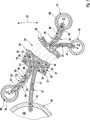
7 sind nur eine Verdampferkanalschicht37 und eine Kondensatorkanalschicht38 vom jeweiligen inneren Ende bis zum jeweiligen äußeren Ende dargestellt, wobei in einem mittleren Bereich eine Unterbrechung eingezeichnet ist, in der sich mehrere Windungen der Wickelstruktur36 befinden.In the simplified representation of 7 are only oneevaporator channel layer 37 and acapacitor channel layer 38 represented from the respective inner end to the respective outer end, wherein in a central region an interruption is shown, in which several turns of the windingstructure 36 are located.

Entsprechend7 kann gemäß einer besonders vorteilhaften Ausführungsform vorgesehen sein, dass je zwei in der Umfangsrichtung28 unmittelbar benachbarte Membranschichten39 jeweils durch einen Längsabschnitt52 einer gemeinsamen Membranbahn53 gebildet sind, die aus besagtem hydrophoben Membranmaterial besteht. Diese beiden Längsabschnitte52 sind an ihren inneren Enden durch eine innere Schlaufe54 der Membranbahn53 und an ihren äußeren Enden durch eine äußere Schlaufe55 der Membranbahn53 miteinander verbunden, so dass die Membranbahn53 eine geschlossen umlaufende, quasi endlos umlaufende Struktur besitzt. Diese Membranbahn53 umschließt dabei einen Kondensateinlasskanal30, einen Kondensatauslasskanal31 und die zugehörige Kondensatkanalschicht38. Zur Ausbildung dieser Kondensatkanalschicht38 ist zwischen den Längsabschnitten52, also wieder innerhalb der Membranbahn53 eine innere Spacer-Materialbahn56 angeordnet, die verhindert, dass die beiden Längsabschnitte52 unmittelbar miteinander in Kontakt kommen. Die innere Spacer-Materialbahn56 besteht aus einer durchströmbaren Struktur, beispielsweise aus einer Gitterstruktur oder Gewebestruktur. Erkennbar ragt die innere Spacer-Materialbahn56 radial innen durch die Verbindungsöffnung51 des Kondensatorauslassrohrs50 in den Kondensatorauslasskanal31 hinein. Radial außen ragt diese innere Spacer-Materialbahn56 durch die Verbindungsöffnung49 des Kondensatoreinlassrohrs48 in den Kondensatoreinlasskanal30 hinein. Somit wird eine fluidische Verbindung vom jeweiligen Kondensatoreinlasskanal30 durch die jeweilige Kondensatorkanalschicht38 zum jeweiligen Kondensatorauslasskanal31 geschaffen, die vollständig von der Membranbahn53 eingefasst ist, so dass keine Leckagegefahr besteht.Corresponding 7 may be provided according to a particularly advantageous embodiment, that each two in thecircumferential direction 28 immediately adjacent membrane layers 39 each by a longitudinal section 52 acommon membrane membrane 53 are formed, which consists of said hydrophobic membrane material. These twolongitudinal sections 52 are at their inner ends by aninner loop 54 themembrane web 53 and at its outer ends by anouter loop 55 themembrane web 53 interconnected so that themembrane membrane 53 has a closed circumferential, almost endlessly circulating structure. Thismembrane membrane 53 encloses acondensate inlet channel 30 , acondensate outlet duct 31 and the associatedcondensate channel layer 38 , To form thiscondensate channel layer 38 is between thelongitudinal sections 52 , so again inside themembrane membrane 53 an innerspacer material web 56 arranged, which prevents the twolongitudinal sections 52 come into direct contact with each other. The innerspacer material web 56 consists of a flow-through structure, for example of a grid structure or fabric structure. Visible protrudes the innerspacer material web 56 radially inward through the connection opening 51 of thecondenser outlet tube 50 in theKondensatorenauslasskanal 31 into it. Radially outwardly protrudes this innerspacer material web 56 by the connection opening 49 of thecondenser inlet pipe 48 into thecondenser inlet duct 30 into it. Thus, a fluidic connection from the respectivecondenser inlet channel 30 through the respectivecapacitor channel layer 38 to therespective Kondensatorenauslasskanal 31 created completely from themembrane membrane 53 is enclosed, so there is no risk of leakage.

Ferner ist7 entnehmbar, dass zwischen zwei in der Umfangsrichtung28 benachbarten Membranbahnen53 eine äußere Spacer-Materialbahn57 angeordnet ist. Die jeweilige äußere Spacer-Materialbahn57 definiert dabei zwischen einander zugewandten Längsabschnitten52 dieser beiden benachbarten Membranbahnen53 jeweils eine Verdampferkanalschicht37. Die äußere Spacer-Materialbahn57 besteht aus einer durchströmbaren Struktur, beispielsweise aus einer Gitterstruktur oder Gewebestruktur. Gemäß7 ragt die jeweilige äußere Spacer-Materialbahn57 radial innen durch die Verbindungsöffnung45 des Verdampfereinlassrohrs44 in den Verdampfereinlasskanal25 hinein. Radial außen ragt die jeweilige äußere Spacer-Materialbahn57 durch die Verbindungsöffnung47 des Verdampferauslassrohrs46 in den Verdampferauslasskanal27 hinein. Auf diese Weise wird die fluidische Verbindung zwischen dem Verdampfereinlasskanal25 durch die jeweilige Verdampferkanalschicht37 zum jeweiligen Verdampferauslasskanal27 geschaffen. Auch hier kann einfach eine hinreichende Abdichtung gegenüber Leckagen realisiert werden, indem der Gehäusemantel22 den gesamten Spiralkörper36 radial außen in der Umfangsrichtung28 komplett einfasst. Insoweit ist der Verdampferpfad3 innerhalb des Gehäuses2 dicht eingefasst. Gegenüber dem Kondensatorpfad5 erfolgt die Abdichtung durch die Membranbahnen53. Es ist klar, dass die Abdichtung zwischen dem Verdampferpfad3 und dem Kondensatorpfad5 durch die Membranstruktur4 nur hinsichtlich der Flüssigphase ist, nicht jedoch gegenüber der Dampfphase, so dass gasförmiges Verdampfungsmittel ohne Weiteres von der jeweiligen Verdampferkanalschicht37 durch die jeweilige Membranschicht39 hindurch in die jeweilige Kondensatorkanalschicht38 gelangen kann.Further is 7 removable, that between two in thecircumferential direction 28adjacent membrane webs 53 an outerspacer material web 57 is arranged. The respective outerspacer material web 57 defines between facinglongitudinal sections 52 these twoadjacent membrane webs 53 one evaporator channel layer each 37 , The outerspacer material web 57 consists of a flow-through structure, for example of a grid structure or fabric structure. According to 7 protrudes the respective outerspacer material web 57 radially inward through theconnection opening 45 theevaporator inlet tube 44 into theevaporator inlet channel 25 into it. Radially outwardly protrudes the respective outerspacer material web 57 through the connection opening 47 of theevaporator outlet pipe 46 in theevaporator outlet channel 27 into it. In this way, the fluidic connection between theevaporator inlet channel 25 through the respectiveevaporator channel layer 37 to the respectiveevaporator outlet channel 27 created. Again, simply a sufficient seal against leaks can be realized by thehousing shell 22 theentire spiral body 36 radially outward in thecircumferential direction 28 completely enclosed. In that regard, theevaporator path 3 inside thecase 2 tightly edged. Opposite thecapacitor path 5 the seal is carried out by themembrane webs 53 , It is clear that the seal between theevaporator path 3 and thecapacitor path 5 through themembrane structure 4 only with respect to the liquid phase, but not with respect to the vapor phase, so that gaseous evaporation agent readily from the respectiveevaporator channel layer 37 through therespective membrane layer 39 through into the respectivecapacitor channel layer 38 can get.

Erkennbar sind die Destillationsmembranen35 hier so konfiguriert, dass die Membranschichten39 einerseits dem in der Verdampferkanalschicht37 geführten Verdampfungsmittel und andererseits dem in der Kondensatorkanalschicht38 geführten Kondensationsmittel jeweils unmittelbar ausgesetzt sind. Dementsprechend arbeitet das hier vorgestellte Destillationsmodul2 vorzugsweise nach dem DCMD-Verfahren. Alternativ kann zwischen der jeweiligen Membranschicht39 und der zugehörigen Kondensatorkanalschicht38 ein Spalt ausgebildet sein, um das Destillationsmodul2 nach dem AGMD-Verfahren oder nach dem VMD-Verfahren oder nach dem SWGMD-Verfahren betreiben zu können.Visible are thedistillation membranes 35 configured here so that the membrane layers 39 on the one hand in theevaporator channel layer 37 guided evaporating agent and on the other hand in thecondenser channel layer 38 guided condensing agent are each directly exposed. Accordingly, the distillation module presented here works 2 preferably by the DCMD method. Alternatively, between therespective membrane layer 39 and the associated capacitor channel layer 38 a gap may be formed around thedistillation module 2 to operate according to the AGMD method or according to the VMD method or according to the SWGMD method.

Für den Fall, dass die hier vorgestellte Destillationseinrichtung1 zur Meerwasserentsalzung verwendet wird, wird dem Verdampfereinlass7 Salzwasser mit einem ersten Salzgehalt zugeführt, während am Verdampferauslass12 Salzwasser mit einem erhöhten zweiten Salzgehalt abgeführt wird. Dem Kondensatoreinlass14 wird eine erste Menge an Süßwasser zugeführt, während am Kondensatorauslass17 eine größere zweite Menge an Süßwasser abgeführt wird.In the event that the distillation device presented here 1 is used for seawater desalination, theevaporator inlet 7 Salt water fed with a first salinity while at theevaporator outlet 12 Salt water is removed with an increased second salt content. The condenser inlet 14 a first amount of fresh water is supplied while at the condenser outlet 17 a larger second amount of fresh water is removed.

ZITATE ENTHALTEN IN DER BESCHREIBUNG QUOTES INCLUDE IN THE DESCRIPTION

Diese Liste der vom Anmelder aufgeführten Dokumente wurde automatisiert erzeugt und ist ausschließlich zur besseren Information des Lesers aufgenommen. Die Liste ist nicht Bestandteil der deutschen Patent- bzw. Gebrauchsmusteranmeldung. Das DPMA übernimmt keinerlei Haftung für etwaige Fehler oder Auslassungen.This list of the documents listed by the applicant has been generated automatically and is included solely for the better information of the reader. The list is not part of the German patent or utility model application. The DPMA assumes no liability for any errors or omissions.

Zitierte PatentliteraturCited patent literature

  • DE 102004013647 A1[0006]DE 102004013647 A1[0006]
  • DE 102004040950 A1[0007]DE 102004040950 A1[0007]
  • DE 4008066 C2[0008]DE 4008066 C2[0008]
  • EP 1029583 A1[0009]EP 1029583 A1[0009]
  • DE 20303013 U1[0009]DE 20303013 U1[0009]
  • DE 1517915 A[0009]DE 1517915 A[0009]

Claims (15)

Translated fromGerman
Destillationsmodul für eine Membrandestillation, – mit mindestens einem Verdampfereinlasskanal (25), der eine Verdampfereinlassöffnung (26) aufweist, – mit mehreren Verdampferauslasskanälen (27), die jeweils eine Verdampferauslassöffnung (32) aufweisen, – mit mehreren Kondensatoreinlasskanälen (30), die jeweils eine Kondensatoreinlassöffnung (33) aufweisen, – mit mehreren Kondensatorauslasskanälen (31), die jeweils eine Kondensatorauslassöffnung (34) aufweisen, – mit mehreren spiralförmig um den Verdampfereinlasskanal (25) und die Kondensatorauslasskanäle (31) gewickelten Destillationsmembranen (35), die mehrere Verdampferkanalschichten (37), mehrere Kondensatorkanalschichten (38) und mehrere, jeweils zwischen einer Verdampferkanalschicht (37) und einer Kondensatorkanalschicht (38) angeordnete Membranschichten (39) aus Membranmaterial ausbilden, – mit einem Gehäuse (21), das einen ersten Endboden (23) und einen dem ersten Endboden (23) axial gegenüberliegenden zweiten Endboden (24) aufweist, – wobei die Verdampferkanalschichten (37) jeweils den Verdampfereinlasskanal (25) mit je einem Verdampferauslasskanal (27) fluidisch verbinden, – wobei die Kondensatorkanalschichten (38) jeweils einen Kondensatoreinlasskanal (30) mit je einem Kondensatorauslasskanal (31) fluidisch verbinden, – wobei der erste Endboden (23) einen mit der Verdampfereinlassöffnung (26) fluidisch verbundenen Verdampfereinlass (7) und einen mit den Kondensatoreinlassöffnungen (33) fluidisch verbundenen Kondensatoreinlass (14) aufweist, – wobei der zweite Endboden (24) einen mit den Verdampferauslassöffnungen (32) fluidisch verbundenen Verdampferauslass (12) und einen mit den Kondensatorauslassöffnungen (34) fluidisch verbundenen Kondensatorauslass (17) aufweist.Distillation module for a membrane distillation, - with at least one evaporator inlet channel ( 25 ) having an evaporator inlet opening ( 26 ), - with a plurality of evaporator outlet channels ( 27 ), each having an evaporator outlet ( 32 ), - with a plurality of condenser inlet ducts ( 30 ), each having a condenser inlet opening ( 33 ), - with several Kondensatorenauslasskanälen ( 31 ), each having a Kondensatorenauslassöffnung ( 34 ), with a plurality of spirals around the evaporator inlet channel ( 25 ) and the Kondensatorenauslasskanäle ( 31 ) wound distillation membranes ( 35 ) containing multiple evaporator channel layers ( 37 ), several capacitor channel layers ( 38 ) and several, each between an evaporator channel layer ( 37 ) and a capacitor channel layer ( 38 ) arranged membrane layers ( 39 ) of membrane material, - with a housing ( 21 ), which has a first end floor ( 23 ) and a first end floor ( 23 ) axially opposite second end floor ( 24 ), wherein the evaporator channel layers ( 37 ) each of the evaporator inlet channel ( 25 ) each with an evaporator outlet channel ( 27 ), wherein - the capacitor channel layers ( 38 ) each have a condenser inlet channel ( 30 ) each with a Kondensatorenauslasskanal ( 31 ) fluidically, - wherein the first end floor ( 23 ) one with the evaporator inlet opening ( 26 ) fluidically connected evaporator inlet ( 7 ) and one with the condenser inlet openings ( 33 ) fluidically connected capacitor inlet ( 14 ), - wherein the second end floor ( 24 ) one with the evaporator outlet openings ( 32 ) fluidically connected evaporator outlet ( 12 ) and one with the Kondensatorenauslassöffnungen ( 34 ) fluidically connected capacitor outlet ( 17 ) having. Modul nach Anspruch 1,dadurch gekennzeichnet, dass der erste Endboden (23) einen ringförmigen Verteilerkanal (42) enthält, der den Kondensateinlass (14) mit den Kondensateinlassöffnungen (33) fluidisch verbindet.Module according to claim 1,characterized in that the first end floor ( 23 ) an annular distribution channel ( 42 ) containing the condensate inlet ( 14 ) with the condensate inlet openings ( 33 ) fluidly connects. Modul nach Anspruch 1 oder 2,dadurch gekennzeichnet, dass am ersten Endboden (23) der Verdampfereinlass (7) zentrisch angeordnet ist, während der Kondensatoreinlass (14) exzentrisch angeordnet ist.Module according to claim 1 or 2,characterized in that at the first end floor ( 23 ) the evaporator inlet ( 7 ) is arranged centrically, while the condenser inlet ( 14 ) is arranged eccentrically. Modul nach einem der Ansprüche 1 bis 3,dadurch gekennzeichnet, dass der zweite Endboden (24) einen ringförmigen Sammelkanal (43) enthält, der die Verdampferauslassöffnungen (32) mit dem Verdampferauslass (12) fluidisch verbindet.Module according to one of claims 1 to 3,characterized in that the second end floor ( 24 ) an annular collecting channel ( 43 ) containing the evaporator outlet openings ( 32 ) with the evaporator outlet ( 12 ) fluidly connects. Modul nach einem der Ansprüche 1 bis 4,dadurch gekennzeichnet, dass am zweiten Endboden (24) der Kondensatorauslass (17) zentrisch angeordnet ist, während der Verdampferauslass (12) exzentrisch angeordnet ist.Module according to one of claims 1 to 4,characterized in that on the second end floor ( 24 ) the capacitor outlet ( 17 ) is arranged centrically, while the evaporator outlet ( 12 ) is arranged eccentrically. Modul nach einem der Ansprüche 1 bis 5,dadurch gekennzeichnet, dass der Verdampfereinlasskanal (25) mit einem Verdampfereinlassrohr (44) gebildet ist, das an einem dem ersten Endboden (23) zugewandten ersten Ende axial offen ist und die Verdampfereinlassöffnung (26) bildet, das an einem dem zweiten Endboden (24) zugewandten zweiten Ende axial verschlossen ist und das für zumindest eine oder für jede Verdampferkanalschicht (37) wenigstens eine radiale Verbindungsöffnung (45) aufweist, durch die der durch den Innenraum des Verdampfereinlassrohrs (44) gebildete Verdampfereinlasskanal (25) mit der jeweiligen Verdampferkanalschicht (37) fluidisch verbunden ist.Module according to one of claims 1 to 5,characterized in that the evaporator inlet channel ( 25 ) with an evaporator inlet tube ( 44 ) formed on a first end floor ( 23 ) facing the first end is axially open and the evaporator inlet opening ( 26 ) formed on a second end floor ( 24 ) is axially closed and that for at least one or each evaporator channel layer ( 37 ) at least one radial connection opening ( 45 ), through which the through the interior of the evaporator inlet tube ( 44 ) formed evaporator inlet channel ( 25 ) with the respective evaporator channel layer ( 37 ) is fluidly connected. Modul nach einem der Ansprüche 1 bis 6,dadurch gekennzeichnet, dass der jeweilige Verdampferauslasskanal (27) mit einem Verdampferauslassrohr (46) gebildet ist, das an einem dem ersten Endboden (23) zugewandten ersten Ende axial verschlossen ist, das an einem dem zweiten Endboden (24) zugewandten zweiten Ende axial offen ist und die jeweilige Verdampferauslassöffnung (32) bildet und das für eine der Verdampferkanalschichten (37) wenigstens eine radiale Verbindungsöffnung (47) aufweist, durch die der durch den Innenraum des Verdampferauslassrohrs (46) gebildete Verdampferauslasskanal (27) mit der jeweiligen Verdampferkanalschicht (37) fluidisch verbunden ist.Module according to one of claims 1 to 6,characterized in that the respective evaporator outlet channel ( 27 ) with an evaporator outlet tube ( 46 ) formed on a first end floor ( 23 ) facing the first end is axially closed, which at a second end floor ( 24 ) facing the second end is axially open and the respective evaporator outlet ( 32 ) and that for one of the evaporator channel layers ( 37 ) at least one radial connection opening ( 47 ), through which the through the interior of the evaporator outlet ( 46 ) formed evaporator outlet channel ( 27 ) with the respective evaporator channel layer ( 37 ) is fluidly connected. Modul nach einem der Ansprüche 1 bis 7,dadurch gekennzeichnet, dass der jeweilige Kondensatoreinlasskanal (30) mit einem Kondensatorenlassrohr (48) gebildet ist, das an einem dem ersten Endboden (23) zugewandten ersten Ende axial offen ist und die jeweilige Kondensatoreinlassöffnung (33) bildet, das an einem dem zweiten Endboden (24) zugewandten zweiten Ende axial verschlossen ist und das für eine der Kondensatorkanalschichten (38) wenigstens eine radiale Verbindungsöffnung (49) aufweist, durch die der durch den Innenraum des Kondensatoreinlassrohrs (48) gebildete Kondensatoreinlasskanal (30) mit der jeweiligen Kondensatorkanalschicht (38) fluidisch verbunden ist.Module according to one of claims 1 to 7,characterized in that the respective condenser inlet channel ( 30 ) with a Kondensatorenlassrohr ( 48 ) formed on a first end floor ( 23 ) facing the first end is axially open and the respective condenser inlet opening ( 33 ) forms at one the second End floor ( 24 ) is closed axially facing and that for one of the capacitor channel layers ( 38 ) at least one radial connection opening ( 49 ), through which the through the interior of the condenser inlet tube ( 48 ) formed condenser inlet channel ( 30 ) with the respective capacitor channel layer ( 38 ) is fluidly connected. Modul nach einem der Ansprüche 1 bis 8,dadurch gekennzeichnet, dass der jeweilige Kondensatorauslasskanal (31) mit einem Kondensatorauslassrohr (50) gebildet ist, das an einem dem ersten Endboden (23) zugewandten ersten Ende axial verschlossen ist, das an einem dem zweiten Endboden (24) zugewandten zweiten Ende axial offen ist und die jeweilige Kondensatorauslassöffnung (34) bildet und das für eine der Kondensatorkanalschichten (38) wenigstens eine radiale Verbindungsöffnung (51) aufweist, durch die der durch den Innenraum des Kondensatorauslassrohrs (50) gebildete Kondensatorauslasskanal (31) mit der jeweiligen Kondensatorkanalschicht (38) fluidisch verbunden ist.Module according to one of claims 1 to 8,characterized in that the respective Kondensatorenauslasskanal ( 31 ) with a condenser outlet tube ( 50 ) formed on a first end floor ( 23 ) facing the first end is axially closed, which at a second end floor ( 24 ) facing the second end is axially open and the respective Kondensatorauslassöffnung ( 34 ) and that for one of the capacitor channel layers ( 38 ) at least one radial connection opening ( 51 ), through which the through the interior of the Kondensatorenauslasss ( 50 ) formed Kondensatorenlasslasskanal ( 31 ) with the respective capacitor channel layer ( 38 ) is fluidly connected. Modul nach einem der Ansprüche 1 bis 9,dadurch gekennzeichnet, – dass je zwei in Umfangsrichtung (28) benachbarte Membranschichten (39) jeweils durch einen Längsabschnitt (52) einer gemeinsamen Membranbahn (53) aus dem Membranmaterial gebildet sind, – dass die beiden Längsabschnitte (52) an ihren inneren Enden durch eine innere Schlaufe (54) der Membranbahn (53) und an ihren äußeren Enden durch eine äußere Schlaufe (55) der Membranbahn (53) miteinander verbunden sind, – dass zwischen den Längsabschnitten (52) eine innere Spacer-Materialbahn (56) angeordnet ist, die zwischen diesen Längsabschnitten (52) die jeweilige Verdampferkanalschicht (37) oder die jeweilige Kondensatorkanalschicht (38) definiert.Module according to one of claims 1 to 9,characterized in that - two each in the circumferential direction ( 28 ) adjacent membrane layers ( 39 ) each by a longitudinal section ( 52 ) of a common membrane web ( 53 ) are formed from the membrane material, - that the two longitudinal sections ( 52 ) at its inner ends by an inner loop ( 54 ) of the membrane web ( 53 ) and at their outer ends by an outer loop ( 55 ) of the membrane web ( 53 ), that between the longitudinal sections ( 52 ) an inner spacer material web ( 56 ) arranged between these longitudinal sections ( 52 ) the respective evaporator channel layer ( 37 ) or the respective capacitor channel layer ( 38 ) Are defined. Modul nach den Ansprüchen 8 bis 10,dadurch gekennzeichnet, – dass die jeweilige innere Spacer-Materialbahn (56) eine Kondensatorkanalschicht (38) definiert und radial innen durch die Verbindungsöffnung (51) eines der Kondensatorauslassrohre (50) in den jeweiligen Kondensatorauslasskanal (31) hineinragt, während sie radial außen durch die Verbindungsöffnung (49) eines solchen Kondensatoreinlassrohrs (48) in den jeweiligen Kondensatoreinlasskanal (30) hineinragt, – dass die innere Schlaufe (54) das jeweilige Kondensatorauslassrohr (50) umschlingt, während die äußere Schlaufe (55) das jeweilige Kondensatoreinlassrohr (48) umschlingt.Module according to claims 8 to 10,characterized in that - the respective inner spacer material web ( 56 ) a capacitor channel layer ( 38 ) and radially inwardly through the connection opening ( 51 ) one of the condenser outlet tubes ( 50 ) in the respective Kondensatorenauslasskanal ( 31 protrudes radially outwardly through the connection opening (FIG. 49 ) of such a condenser inlet pipe ( 48 ) into the respective condenser inlet duct ( 30 ), that the inner loop ( 54 ) the respective Kondensatorenauslassrohr ( 50 ), while the outer loop ( 55 ) the respective condenser inlet pipe ( 48 ) wraps around. Modul nach Anspruch 10 oder 11,dadurch gekennzeichnet, dass zwischen zwei in der Umfangsrichtung (28) benachbarten Membranbahnen (52) eine äußere Spacer-Materialbahn (57) angeordnet ist, die zwischen den einander zugewandten Längsabschnitten (52) dieser beiden Membranbahnen (52) die jeweilige Kondensatorkanalschicht (38) oder die jeweilige Verdampferkanalschicht (37) definiert.Module according to claim 10 or 11,characterized in that between two in the circumferential direction ( 28 ) adjacent membrane webs ( 52 ) an outer spacer material web ( 57 ) is arranged between the mutually facing longitudinal sections ( 52 ) of these two membrane webs ( 52 ) the respective capacitor channel layer ( 38 ) or the respective evaporator channel layer ( 37 ) Are defined. Modul nach Anspruch 12 sowie nach den Ansprüchen 6 und 7,dadurch gekennzeichnet, dass die jeweilige äußere Spacer-Materialbahn (57) eine Verdampferkanalschicht (37) definiert und radial innen durch eine der Verbindungsöffnungen (45) des Verdampfereinlassrohrs (44) in den Verdampfereinlasskanal (25) hineinragt, während sie radial außen durch die Verbindungsöffnung (47) eines solchen Verdampferauslassrohrs (46) in den Verdampferauslasskanal (27) hineinragt.Module according to claim 12 and according to claims 6 and 7,characterized in that the respective outer spacer material web ( 57 ) an evaporator channel layer ( 37 ) and radially inwardly through one of the connection openings ( 45 ) of the evaporator inlet tube ( 44 ) into the evaporator inlet channel ( 25 protrudes radially outwardly through the connection opening (FIG. 47 ) of such an evaporator outlet tube ( 46 ) in the evaporator outlet channel ( 27 ) protrudes. Modul nach einem der Ansprüche 1 bis 13,dadurch gekennzeichnet, dass innerhalb der jeweiligen Destillationsmembran (35) die Membranschicht (39) einerseits dem in der Verdampferkanalschicht (37) geführten Verdampfungsmittel und andererseits dem in der Kondensatorkanalschicht (38) geführten Kondensationsmittel unmittelbar ausgesetzt ist.Module according to one of claims 1 to 13,characterized in that within the respective distillation membrane ( 35 ) the membrane layer ( 39 ) on the one hand in the evaporator channel layer ( 37 ) and on the other hand, in the condenser channel layer ( 38 ) is directly exposed to condensing agent. Destillationseinrichtung, insbesondere Meerwasserentsalzungseinrichtung, – mit wenigstens einem Destillationsmodul (2) nach einem der Ansprüche 1 bis 14, – mit einer Verdampferzuführung (6) zum Zuführen einer Verdampferflüssigkeit, – mit einer Kondensatorzuführung (13) zum Zuführen einer Kondensatorflüssigkeit, – mit einer Verdampferabführung (11) zum Abführen eines Retentats, – mit einer Kondensatorabführung (16) zum Abführen eines Destillats.Distillation device, in particular seawater desalination device, with at least one distillation module ( 2 ) according to one of claims 1 to 14, - with an evaporator feed ( 6 ) for supplying an evaporator liquid, - with a condenser feed ( 13 ) for supplying a condenser liquid, - with an evaporator discharge ( 11 ) for removing a retentate, - with a condenser discharge ( 16 ) for discharging a distillate.
DE102016204451.6A2016-03-172016-03-17 Distillation device with a distillation module for a membrane distillationWithdrawnDE102016204451A1 (en)

Priority Applications (1)

Application NumberPriority DateFiling DateTitle
DE102016204451.6ADE102016204451A1 (en)2016-03-172016-03-17 Distillation device with a distillation module for a membrane distillation

Applications Claiming Priority (1)

Application NumberPriority DateFiling DateTitle
DE102016204451.6ADE102016204451A1 (en)2016-03-172016-03-17 Distillation device with a distillation module for a membrane distillation

Publications (1)

Publication NumberPublication Date
DE102016204451A1true DE102016204451A1 (en)2017-09-21

Family

ID=59751726

Family Applications (1)

Application NumberTitlePriority DateFiling Date
DE102016204451.6AWithdrawnDE102016204451A1 (en)2016-03-172016-03-17 Distillation device with a distillation module for a membrane distillation

Country Status (1)

CountryLink
DE (1)DE102016204451A1 (en)

Cited By (1)

* Cited by examiner, † Cited by third party
Publication numberPriority datePublication dateAssigneeTitle
IT202200021321A1 (en)*2022-10-172024-04-17Carlo Eugenio Isetti REFRIGERATION CYCLE INTEGRATED INTO A HYDRAULIC CIRCUIT FOR MEMBRANE DISTILLATION OF WATER

Citations (7)

* Cited by examiner, † Cited by third party
Publication numberPriority datePublication dateAssigneeTitle
DE1517915A1 (en)1965-03-221970-01-29Gulf General Atomic Inc Diaphragm assembly and process for making same
DE4008066C2 (en)1990-02-031992-04-23Institut Fuer Entwicklung Und Forschung Dr. Vielberth Kg, 8400 Regensburg, De
EP1029583A1 (en)1998-06-182000-08-23Toray Industries, Inc.Spiral reverse osmosis membrane element, reverse osmosis membrane module using it, device and method for reverse osmosis separation incorporating the module
DE20303013U1 (en)2003-02-072003-06-05Rochem RO-Wasserbehandlung GmbH, 21077 Hamburg Device for filtering and separating flow media
DE102004013647A1 (en)2004-03-192005-10-06Wolfgang Heinzl Process and apparatus for distillation of solutions
WO2006015461A1 (en)*2004-08-112006-02-16Vlaamse Instelling Voor Technologisch Onderzoek (Vito)Integrated permeate channel membrane
DE102004040950A1 (en)2004-08-242006-03-02Krelle, Jürgen, Dipl.-Phys.Distillation process with improved energy recovery, especially for obtaining fresh water, using liquid channel with microporous membrane or vapor-permeable film, vapor channel and condensation wall

Patent Citations (7)

* Cited by examiner, † Cited by third party
Publication numberPriority datePublication dateAssigneeTitle
DE1517915A1 (en)1965-03-221970-01-29Gulf General Atomic Inc Diaphragm assembly and process for making same
DE4008066C2 (en)1990-02-031992-04-23Institut Fuer Entwicklung Und Forschung Dr. Vielberth Kg, 8400 Regensburg, De
EP1029583A1 (en)1998-06-182000-08-23Toray Industries, Inc.Spiral reverse osmosis membrane element, reverse osmosis membrane module using it, device and method for reverse osmosis separation incorporating the module
DE20303013U1 (en)2003-02-072003-06-05Rochem RO-Wasserbehandlung GmbH, 21077 Hamburg Device for filtering and separating flow media
DE102004013647A1 (en)2004-03-192005-10-06Wolfgang Heinzl Process and apparatus for distillation of solutions
WO2006015461A1 (en)*2004-08-112006-02-16Vlaamse Instelling Voor Technologisch Onderzoek (Vito)Integrated permeate channel membrane
DE102004040950A1 (en)2004-08-242006-03-02Krelle, Jürgen, Dipl.-Phys.Distillation process with improved energy recovery, especially for obtaining fresh water, using liquid channel with microporous membrane or vapor-permeable film, vapor channel and condensation wall

Non-Patent Citations (1)

* Cited by examiner, † Cited by third party
Title
KOSCHIKOWSKI Joachim: Entwicklung von energieautark arbeitenden Wasserentsalzungsanlagen auf Basis der Membrandestillation. Stuttgart: Fraunhofer, 2011. Seiten 30 - 38, 98 - 105 und 132 - 133. – ISBN 978-3-8396-0260-7*

Cited By (1)

* Cited by examiner, † Cited by third party
Publication numberPriority datePublication dateAssigneeTitle
IT202200021321A1 (en)*2022-10-172024-04-17Carlo Eugenio Isetti REFRIGERATION CYCLE INTEGRATED INTO A HYDRAULIC CIRCUIT FOR MEMBRANE DISTILLATION OF WATER

Similar Documents

PublicationPublication DateTitle
EP2427264B1 (en)Membrane distillation device and process using the same
DE69208099T2 (en) Multiple bundle permeation device.
DE10011785A1 (en)Gas separation membrane module for separating mixed gases, has film-like material on periphery of hollow fiber bundle inside which mixed gas is passed when passing carrier gas outside in counterflow direction
EP0214496A2 (en)Apparatus for separating mixtures by pervaporization
DE10323440B4 (en) Membrane tube module
DE69005326T2 (en) Connection for membrane elements for fluid separation.
EP0891221A1 (en)Membrane module for a membrane separation system, its use and process for producing the same
DE2143330A1 (en) MULTI-STAGE EVAPORATOR FOR LIQUID DISTILLATION FROM SOLUTIONS CONTAINING NON-VOLATILE COMPONENTS, IN PARTICULAR WATER FROM SEA WATER OR. DGL
DE102013223562A1 (en) Device for separating water from a fluid stream containing water
DE102013220199A1 (en) Membrane distillation apparatus and method for membrane distillation
DE102016204451A1 (en) Distillation device with a distillation module for a membrane distillation
DE2814326A1 (en) POROESE SUPPORT FOR USE IN A DIVIDER WITH HOLLOW FIBER
DE102012201869B4 (en) Multi-stage tubular heat exchanger device, in particular for desalination of sea water
EP0823861B1 (en)Fluid separation device
DE2350068C3 (en) Multi-stage evaporator
AT523715B1 (en) METHOD AND DEVICE FOR DESALINATING SOLUTIONS
DE3023094C2 (en) Device for generating steam
EP3395767B1 (en)Reverse osmosis module with coaxial internal pipe
DE102016204452A1 (en) distillation device
DE2103289C3 (en) Multi-body falling film evaporator
DE3230814C1 (en)Apparatus for separating solvent from a solution
WO1985000297A1 (en)Process and device for the separation of substances by means of membranes
EP3317000B1 (en)Device and method for osmotic distillation
DE1519678B2 (en) DISTILLATION DEVICE
EP1165212B1 (en)Method and device of separating substance mixtures in liquid and/or vapour form by pervaporation and/or vapour permeation

Legal Events

DateCodeTitleDescription
R082Change of representative

Representative=s name:BRP RENAUD UND PARTNER MBB RECHTSANWAELTE PATE, DE

R163Identified publications notified
R119Application deemed withdrawn, or ip right lapsed, due to non-payment of renewal fee

[8]ページ先頭

©2009-2025 Movatter.jp