DE102016203661A1 - Pedelec drive arrangement - Google Patents
Pedelec drive arrangementDownload PDFInfo
- Publication number
- DE102016203661A1 DE102016203661A1DE102016203661.0ADE102016203661ADE102016203661A1DE 102016203661 A1DE102016203661 A1DE 102016203661A1DE 102016203661 ADE102016203661 ADE 102016203661ADE 102016203661 A1DE102016203661 A1DE 102016203661A1
- Authority
- DE
- Germany
- Prior art keywords
- planetary gear
- transmission
- input shaft
- output shaft
- drive arrangement
- Prior art date
- Legal status (The legal status is an assumption and is not a legal conclusion. Google has not performed a legal analysis and makes no representation as to the accuracy of the status listed.)
- Ceased
Links
- 230000005540biological transmissionEffects0.000claimsabstractdescription71
- 238000013519translationMethods0.000claimsabstractdescription11
- 238000011144upstream manufacturingMethods0.000claimsabstractdescription9
- 230000008878couplingEffects0.000description9
- 238000010168coupling processMethods0.000description9
- 238000005859coupling reactionMethods0.000description9
- 238000005259measurementMethods0.000description8
- 238000005452bendingMethods0.000description3
- 238000004364calculation methodMethods0.000description2
- 238000006243chemical reactionMethods0.000description2
- 230000033001locomotionEffects0.000description2
- 238000000034methodMethods0.000description2
- 238000012549trainingMethods0.000description2
- 238000012546transferMethods0.000description2
- BUHVIAUBTBOHAG-FOYDDCNASA-N(2r,3r,4s,5r)-2-[6-[[2-(3,5-dimethoxyphenyl)-2-(2-methylphenyl)ethyl]amino]purin-9-yl]-5-(hydroxymethyl)oxolane-3,4-diolChemical compoundCOC1=CC(OC)=CC(C(CNC=2C=3N=CN(C=3N=CN=2)[C@H]2[C@@H]([C@H](O)[C@@H](CO)O2)O)C=2C(=CC=CC=2)C)=C1BUHVIAUBTBOHAG-FOYDDCNASA-N0.000description1
- 230000006978adaptationEffects0.000description1
- 230000000712assemblyEffects0.000description1
- 238000000429assemblyMethods0.000description1
- 230000015572biosynthetic processEffects0.000description1
- 238000010276constructionMethods0.000description1
- 230000001419dependent effectEffects0.000description1
- 238000013461designMethods0.000description1
- 238000006073displacement reactionMethods0.000description1
- 238000009826distributionMethods0.000description1
- 230000000694effectsEffects0.000description1
- 230000002349favourable effectEffects0.000description1
- 238000012423maintenanceMethods0.000description1
- 210000003205muscleAnatomy0.000description1
- 230000003287optical effectEffects0.000description1
- 230000000717retained effectEffects0.000description1
Images
Classifications
- B—PERFORMING OPERATIONS; TRANSPORTING
- B62—LAND VEHICLES FOR TRAVELLING OTHERWISE THAN ON RAILS
- B62M—RIDER PROPULSION OF WHEELED VEHICLES OR SLEDGES; POWERED PROPULSION OF SLEDGES OR SINGLE-TRACK CYCLES; TRANSMISSIONS SPECIALLY ADAPTED FOR SUCH VEHICLES
- B62M6/00—Rider propulsion of wheeled vehicles with additional source of power, e.g. combustion engine or electric motor
- B62M6/40—Rider propelled cycles with auxiliary electric motor
- B62M6/55—Rider propelled cycles with auxiliary electric motor power-driven at crank shafts parts
- B—PERFORMING OPERATIONS; TRANSPORTING
- B62—LAND VEHICLES FOR TRAVELLING OTHERWISE THAN ON RAILS
- B62M—RIDER PROPULSION OF WHEELED VEHICLES OR SLEDGES; POWERED PROPULSION OF SLEDGES OR SINGLE-TRACK CYCLES; TRANSMISSIONS SPECIALLY ADAPTED FOR SUCH VEHICLES
- B62M11/00—Transmissions characterised by the use of interengaging toothed wheels or frictionally-engaging wheels
- B62M11/04—Transmissions characterised by the use of interengaging toothed wheels or frictionally-engaging wheels of changeable ratio
- B62M11/12—Transmissions characterised by the use of interengaging toothed wheels or frictionally-engaging wheels of changeable ratio with frictionally-engaging wheels
Landscapes
- Engineering & Computer Science (AREA)
- Chemical & Material Sciences (AREA)
- Combustion & Propulsion (AREA)
- Transportation (AREA)
- Mechanical Engineering (AREA)
- Connection Of Motors, Electrical Generators, Mechanical Devices, And The Like (AREA)
Abstract
Translated fromGermanDescription
Translated fromGermanDie Erfindung bezieht sich auf eine Pedelec-Antriebsanordnung, umfassend
- – eine drehbar in einem Antriebsgehäuse gelagerte Tretkurbelwelle,
- – eine elektrische Maschine mit einem gehäusefesten Stator und einem drehbar dazu gelagerten Rotor und
- – ein stufenlos variierbares Reibrollengetriebe, dessen Getriebe-Eingangswelle einerseits mit der Tretkurbelwelle und andererseits mit dem Rotor der elektrischen Maschine gekoppelt ist und dessen Getriebe-Ausgangswelle ein Abtriebsrad trägt, welches mit einem angetriebenen Rad des Pedelecs koppelbar ist,
- A pedal crankshaft rotatably mounted in a drive housing,
- - An electric machine with a housing fixed stator and a rotatably mounted rotor and
- A continuously variable friction roller gear, the transmission input shaft of which is coupled, on the one hand, to the pedal crankshaft and, on the other hand, to the rotor of the electrical machine and whose transmission output shaft carries a driven gear, which can be coupled to a driven wheel of the pedelec,
Derartige Antriebsanordnungen für Pedelecs sind bekannt aus der
Als Pedelec sei im Rahmen der vorliegenden Beschreibung allgemein ein durch Elektromotor-unterstützte, biomechanische Kurbelkraft angetriebenes Fahrzeug bezeichnet, wobei die biomechanische Kurbelkraft typischerweise wie bei einem herkömmlichen Fahrrad durch Tretbewegungen erzeugt wird, gleichwohl aber auch, wie beispielsweise von sogenannten Hand-Bikes bekannt, durch Armkraft aufgebracht werden kann. Der Begriff soll sowohl ein- als auch mehrspurige Fahrzeuge umfassen. Der leichteren Verständlichkeit halber ist die Formulierung der nachfolgenden Beschreibung im Wesentlichen am Aufbau eines klassischen E-Bikes ausgerichtet; der Fachmann wird jedoch ohne Schwierigkeiten die Übertragung auf andere Formen von Pedelecs vornehmen können.Pedelecs in the context of the present description generally refer to an electric motor-assisted, biomechanical crank-driven vehicle, wherein the biomechanical crank force is typically generated by pedaling movements as in a conventional bicycle, but nevertheless also known, for example from so-called hand-bikes Armkraft can be applied. The term is intended to include both single and multi-lane vehicles. For ease of understanding, the wording of the following description is essentially oriented towards the construction of a classic e-bike; however, the skilled person will be able to easily transfer to other forms of pedelecs.
Die oben genannte, gattungsbildende Druckschrift offenbart ein E-Bike mit einer kombinierten Antriebsanordnung im Tretlagerbereich. In diesem Bereich eines Fahrradrahmens ist ein Antriebsgehäuse angeordnet, in welchem eine Tretkurbelwelle drehbar gelagert ist. Parallel versetzt zu der Tretkurbelwelle ist eine Ausgangswelle gelagert, welche als Abtriebsrad ein Kettenblatt trägt, das über eine Kette mit einem Ritzel an der Hinterradnabe des E-Bikes gekoppelt werden kann. Weiter ist in dem Antriebsgehäuse eine die Tretkurbelwelle koaxial umgreifende elektrische Maschine angeordnet. Schließlich umfasst das Antriebsgehäuse auch ein Doppelkegel-Ring-Regelreibgetriebe nach Kopp, dessen Ausgangswelle das Abtriebsrad trägt und dessen Eingangswelle sowohl mit der Tretkurbelwelle als auch mit dem Rotor der elektrischen Maschine gekoppelt ist. Auf diese Weise lässt sich sowohl biomechanisches Drehmoment, welches über die Tretkurbelwelle eingebracht wird, als auch unterstützendes, elektrisch generiertes Drehmoment auf das Abtriebsrad übertragen, wobei die Übersetzung mittels des Reibrollengetriebes stufenlos anpassbar ist. Dies ermöglicht insbesondere eine automatisierte, lastschaltbare Übersetzungsanpassung.The above, generic document discloses an e-bike with a combined drive assembly in the bottom bracket. In this area of a bicycle frame, a drive housing is arranged, in which a pedal crankshaft is rotatably mounted. Parallel to the pedal crankshaft, an output shaft is mounted, which carries a chainring as a driven gear, which can be coupled via a chain with a pinion on the rear hub of the e-bike. Further, a pedal crankshaft coaxially encompassing electrical machine is arranged in the drive housing. Finally, the drive housing also includes a double-cone-ring Regelreibgetriebe Kopp whose output shaft carries the output gear and the input shaft is coupled to both the pedal crankshaft and with the rotor of the electric machine. In this way, both biomechanical torque, which is introduced via the pedal crankshaft, as well as supporting, electrically generated torque can be transmitted to the driven wheel, wherein the translation is infinitely adjustable by means of the Reibrollengetriebes. In particular, this enables an automated, load-shiftable translation adaptation.
Zur Übertragung der unterschiedlich generierten Drehmomente auf die Eingangswelle des Getriebes sind die Tretkurbelwelle und die elektrische Maschine auf unterschiedliche Weise angekoppelt. Die Ankopplung der Tretkurbelwelle erfolgt über eine dem Getriebe vorgeschaltete Übersetzungsstufe, die als einfache Stirnradstufe ausgebildet ist. Die Ankopplung der elektrischen Maschine erfolgt ebenfalls über eine einfache Stirnradstufe, wobei die Umfangsverteilungen der jeweiligen Stirnradpaarungen den Besonderheiten der jeweiligen Drehmomentquelle entsprechen. So wird die Drehzahl der Tretkurbelwelle durch die zugeordnete Stirnradstufe ins Schnelle übersetzt, wohingegen die Drehzahl der elektrischen Maschine durch die zugeordnete Stirnradstufe ins Langsame übersetzt wird.To transmit the differently generated torques to the input shaft of the transmission, the pedal crankshaft and the electric machine are coupled in different ways. The coupling of the pedal crankshaft via a transmission upstream of the transmission stage, which is designed as a simple spur gear. The coupling of the electric machine also takes place via a simple spur gear, wherein the circumferential distributions of the respective Stirnradpaarungen correspond to the peculiarities of the respective torque source. Thus, the speed of the pedal crankshaft is translated by the associated spur gear speed, whereas the speed of the electric machine is translated by the associated spur gear to slow.
Die genannte Druckschrift lässt das Problem der Drehmomentmessung, insbesondere der Messung des an der Tretkurbel aufgebrachten Drehmomentes, vollkommen offen. Gerade die präzise Drehmomentmessung ist jedoch ein zentrales Element einer praxistauglichen Pedelec-Steuerung. Typischerweise erfolgt die Motorunterstützung nämlich in präzise definierter Abhängigkeit von der vom Fahrer aufgebrachten Tretkraft, mithin von dem auf die Tretkurbelwelle aufgebrachten Drehmoment. Ungenaue Drehmomentmessungen können daher zu temporär inadäquater Motorunterstützung führen, was im Hinblick auf Komfort und Fahrsicherheit nachteilig ist.The cited document leaves the problem of torque measurement, in particular the measurement of the torque applied to the crank, completely open. Precise torque measurement, however, is a central element of a practicable pedelec control system. In fact, the engine assistance typically takes place in a precisely defined dependence on the treading force applied by the driver, that is to say on the torque applied to the pedal crankshaft. Inaccurate torque measurements can therefore lead to temporary inadequate engine assistance, which is disadvantageous in terms of comfort and driving safety.
Aus der sensorgestützten Trainingssteuerung sind etliche Leistungsmess-Prinzipien bekannt, bei denen als drehmoment-repräsentative Größe beispielsweise die Kettenspannung der Antriebskette, die Verbiegung spezieller Biegeelemente in der Nabe des angetriebenen Rades, im Pedal oder gar minimale Verbiegungen der Tretkurbelwelle selbst registriert werden. All diese Verfahren, die stark schwankende Werte generieren, sind zwar als Hinweisverfahren für eine Trainingssteuerung ausreichend; als Basis für die Steuerung der Motorunterstützung eines Pedelecs haben sie sich jedoch als zu wenig konstant erwiesen. Entsprechend wird bei Pedelec-Antrieben hoher Aufwand bei der Drehmomentmessung getrieben, was zu hohen Kosten führt.From the sensor-based training control several performance measurement principles are known in which the torque-representative size, for example, the chain tension of the drive chain, the bending of special bending elements in the hub of the driven wheel, are registered in the pedal or even minimal bending of the pedal crankshaft itself. All these methods, which generate strongly fluctuating values, are sufficient as a hinting procedure for a training control; However, as a basis for controlling the motor assistance of a pedelec, they have proven to be too little constant. Correspondingly, in pedelec drives, high expenditure is required in torque measurement, which leads to high costs.
Es ist die Aufgabe der vorliegenden Erfindung eine gattungsgemäße Pedelec-Antriebsanordnung derart weiterzubilden, dass auf kostengünstige Weise eine präzise Messung des über die Tretkurbelwelle eingebrachten Drehmomentes ermöglicht wird.It is the object of the present invention to further develop a generic pedelec drive arrangement in such a way that a precise measurement of the torque introduced via the pedal crankshaft is made possible in a cost-effective manner.
Diese Aufgabe wird in Verbindung mit den Merkmalen des Oberbegriffs von Anspruch 1 dadurch gelöst, dass die vorgeschaltete Übersetzungsstufe als ein zur Getriebe-Eingangswelle koaxialer Planetensatz mit einer Planetensatz-Eingangswelle, einer ersten Planetensatz-Ausgangswelle und einer zweiten Planetensatz-Ausgangswelle ausgebildet ist, wobei die Planetensatz-Eingangswelle mit der Tretkurbelwelle verbunden ist, die erste Planetensatz-Ausgangswelle mit der Getriebe-Eingangswelle gekoppelt ist und die zweite Planetensatz-Ausgangswelle über einen Drucksensor am Getriebegehäuse festgelegt ist. This object is achieved in conjunction with the features of the preamble of claim 1, characterized in that the upstream gear ratio is formed as a gearbox input shaft coaxial planetary gear set with a planetary gear input shaft, a first planetary gear output shaft and a second planetary gear output shaft, wherein the Planet set input shaft is connected to the pedal crankshaft, the first planetary gear output shaft is coupled to the transmission input shaft and the second planetary gear output shaft is fixed via a pressure sensor on the transmission housing.
Bevorzugte Ausführungsformen der Erfindung sind Gegenstand der abhängigen Ansprüche.Preferred embodiments of the invention are the subject of the dependent claims.
Als wesentliches Merkmal der vorliegenden Erfindung ist die der Getriebe-Eingangswelle vorgeschaltete Übersetzungsstufe, die die Tretkurbelwelle mit der Getriebe-Eingangswelle koppelt, als ein zur Getriebe-Eingangswelle koaxialer Planetensatz ausgebildet. Als Planetensatz wird hier allgemein ein im Grunde bekanntes Planetengetriebe mit einem Hohlrad, einer Sonne und einem Steg bezeichnet, auf welchem Planetenräder drehbar gelagert sind, die einerseits mit der Sonne und andererseits mit dem Hohlrad kämmen. Je nach Ankopplung kann jedes der vorgenannten Planetensatz-Elemente als Eingangs- oder als Ausgangswelle des Planetensatzes dienen. Um eine Übersetzung der Tretbewegung ins Schnelle zu erzeugen ist bevorzugt vorgesehen, dass das Hohlrad als Planetensatz-Eingangswelle dient. Es ist hierzu bevorzugt drehfest mit der Tretkurbelwelle verbunden.As an essential feature of the present invention, the transmission input shaft upstream of the transmission stage, which couples the pedal crankshaft with the transmission input shaft, designed as a gearbox input shaft coaxial planetary gear set. As a planetary gearset is here generally referred to a basically known planetary gear with a ring gear, a sun and a land on which planet gears are rotatably mounted, which mesh on the one hand with the sun and on the other hand with the ring gear. Depending on the coupling, each of the aforementioned planetary gear elements can serve as an input or output shaft of the planetary gearset. In order to produce a translation of the pedaling motion into the fast, it is preferably provided that the ring gear serves as a planetary gearset input shaft. It is preferably rotatably connected to the pedal crankshaft.
Die Ausgestaltung der vorgeschalteten Übersetzungsstufe als ein Planetensatz hat zunächst bereits den Vorteil, dass Tretkurbelwelle und Getriebe-Ein- und Ausgangswelle koaxial zueinander angeordnet sein können, sodass die gewohnte Optik von Tretradantrieben gewahrt bleibt und der beim Stand der Technik notwendige Achsversatz unterbleibt.The design of the upstream gear ratio as a planetary gear set initially has the advantage that pedal crankshaft and transmission input and output shaft can be arranged coaxially to each other, so that the usual appearance of Tretradantrieben is maintained and omits the necessary in the prior art axis offset.
Als weiteres wesentliches Merkmal der Erfindung ist jedoch zusätzlich vorgesehen, dass eine der Planetensatz-Ausgangswellen, nämlich die hier als zweite Planetensatz-Ausgangswelle bezeichnet, am Antriebsgehäuse festgelegt ist. Dem Fachmann ist bekannt, dass ein Planetensatz bei einem festgelegten Planetensatz-Element als einfache Übersetzungsstufe mit definierter Übersetzung wirkt. Diese Übersetzung wirkt zwischen der Planetensatz-Eingangswelle und der hier als erste Planetensatz-Ausgangswelle bezeichneten Ausgangswelle, die ihrerseits mir der Getriebeeingangswelle des nachfolgenden Reibrollengetriebes gekoppelt ist.However, as a further essential feature of the invention, it is additionally provided that one of the planetary gear output shafts, namely the one referred to here as the second planetary gear set output shaft, is fixed to the drive housing. The person skilled in the art is aware that a planetary gear set acts as a simple gear ratio stage with a defined gear ratio in the case of a fixed planetary gearset element. This translation acts between the planetary gearset input shaft and the output shaft, referred to here as the first planetary gear set output shaft, which in turn is coupled to the transmission input shaft of the following frictional roller gear.
Die Erfindung nutzt nun die Erkenntnis, dass die Stützkraft, mit der das festgehaltene Planetensatz-Element abgestützt werden muss, um den Drehmomentenfluss von der Planetensatz-Eingangswelle zur ersten Planetensatz-Ausgangswelle zu ermöglichen, ein präzises Maß für das übertragene Drehmoment ist. Die jeweils tatsächlich anliegende Abstützkraft wird erfindungsgemäß mittels eines Drucksensors gemessen, über den sich die zweite Planetensatz-Ausgangswelle am Antriebsgehäuse abstützt. Drucksensoren sind als präzise arbeitende, wenig bauraumintensive und ausgesprochen kostengünstige Bauteile am Markt erhältlich. Die Umrechnung vom gemessenen Druck zum jeweils anliegenden Drehmoment an der Planetensatz-Eingangswelle, die allein von der Planetensatz-Geometrie (einschließlich seiner Abstützung) abhängt, ist für den Fachmann leicht zu vollziehen bzw. zu kalibrieren. Entsprechende Umrechnungsalgorithmen können in einer elektronischen Antriebssteuereinheit hinterlegt sein. Diese Steuereinheit übernimmt es typischerweise auch, aus den erfassten Sensordaten eine geeignete Ansteuerung für die elektrische Maschine zu generieren.The invention now makes use of the recognition that the support force with which the retained planetary gearset element must be supported in order to enable the torque flow from the planetary gearset input shaft to the first planetary gearset output shaft is a precise measure of the transmitted torque. The respective actual supporting force is measured according to the invention by means of a pressure sensor, via which the second planetary gear output shaft is supported on the drive housing. Pressure sensors are available on the market as precisely working components that are less bulky and extremely cost-effective. The conversion from the measured pressure to the respective applied torque at the planetary gear input shaft, which depends solely on the planetary gear set geometry (including its support), is easy for the skilled person to perform or calibrate. Corresponding conversion algorithms can be stored in an electronic drive control unit. This control unit typically also undertakes to generate a suitable control for the electrical machine from the detected sensor data.
Es ist somit die vorteilhafte Wirkung der vorliegenden Erfindung eine kostengünstige und präzise Drehmomentmessung zur Verfügung zu stellen. Als weiterer Vorteil der Erfindung ist die erzielbare Koaxialität von Tretkurbelwelle und Getriebewellen, insbesondere der Getriebe-Ausgangswelle, anzusehen.It is thus the advantageous effect of the present invention to provide a cost effective and accurate torque measurement. As a further advantage of the invention, the achievable coaxiality of pedal crankshaft and transmission shafts, in particular the transmission output shaft is to be regarded.
Wie erläutert, ist bevorzugt das Hohlrad des Planetensatzes als die Planetensatz-Eingangswelle ausgebildet. Hieraus ergeben sich zwei Möglichkeiten zur Nutzung von Steg und Sonne als Planetensatz-Ausgangswellen. Bei einer ersten Ausführungsform ist vorgesehen, dass die Sonne des Planetensatzes als die erste Planetensatzausgangswelle und sein Steg als die zweite Planetensatz-Ausgangswelle ausgebildet ist. Hieraus folgt, dass zwischen Tretkurbelwelle und Getriebe-Eingangswelle eine Drehrichtungsumkehr stattfindet. Die genannte Anordnung wird daher bevorzugt in Verbindung mit der Ausbildung des Reibrollengetriebes als ein Minus-Getriebe eingesetzt. Als besonders günstige Ausführungsform eines Reibrollen-Minus-Getriebes hat sich das sogenannte Sadivar-Getriebe erwiesen. Beim Sadivar-Getriebe sind zwei im Wesentlichen gleichgroße Reibscheiben über tellerförmige Reibräder miteinander gekoppelt, wobei durch Winkelverstellung der Reibräder eine sehr große Übersetzungsspreizung von der Übersetzung ins Schnelle bis hin zur Übersetzung ins Langsame realisierbar ist. Zur Erzeugung der notwendigen Anpressdrücke und zum Ausgleich der Axialverschiebungen, denen wenigstens eine der Reibscheiben bei Übersetzungsänderung unterworfen ist, ist wenigstens eine der Reibscheiben mittels einer Spreizkupplung, typischerweise einer Kugelrampen-Kupplung, gegen seine zugeordnete Getriebewelle vorgespannt.As explained, the ring gear of the planetary gear set is preferably designed as the planetary gearset input shaft. This results in two ways to use web and sun as planetary gear output shafts. In a first embodiment, it is provided that the sun of the planetary gear set is designed as the first planetary gearset output shaft and its web as the second planetary gearset output shaft. It follows that between the crankshaft and the transmission input shaft, a reversal of direction takes place. The said arrangement is therefore preferably used in connection with the formation of the frictional roller transmission as a minus gear. As a particularly favorable embodiment of a friction roller minus transmission, the so-called Sadivar transmission has proven. In the case of the Sadivar transmission, two essentially identical friction disks are coupled to one another via plate-shaped friction wheels, wherein a very large transmission spread from the transmission to the speed up to the transmission to the low speed can be achieved by angular adjustment of the friction wheels. To generate the necessary contact pressures and to compensate for the Axialverschiebungen, which is subjected to at least one of the friction plates at ratio change, at least one of the friction plates by means of a Spreizkupplung, typically a ball ramp coupling, biased against its associated transmission shaft.
Bei einer anderen Ausführungsform der Erfindung ist hingegen vorgesehen, dass der Steg des Planetensatzes als die erste Planetensatz-Ausgangswelle und seine Sonne als die zweite Planetensatz-Ausgangswelle ausgebildet ist. Bei dieser Anordnung bleibt die Drehrichtung zwischen Tretkurbelwelle und Getriebe-Eingangswelle erhalten. Diese Anordnung empfiehlt sich daher insbesondere in Verbindung mit der Ausgestaltung des Reibrollengetriebes als ein Plus-Getriebe. Als besonders vorteilhaft hat sich hierbei das sogenannte NuVinci-Getriebe erwiesen, welches insbesondere im Zusammenhang mit stufenlosen Nabenschaltungen bekannt ist. In another embodiment of the invention, however, it is provided that the web of the planetary gear set is designed as the first planetary gearset output shaft and its sun as the second planetary gearset output shaft. In this arrangement, the direction of rotation between pedal crankshaft and transmission input shaft is maintained. This arrangement is therefore recommended in particular in connection with the configuration of the frictional roller transmission as a plus gear. Be particularly advantageous in this case, the so-called NuVinci gearbox has proven, which is known in particular in connection with continuously variable hub gears.
Bei einer bevorzugten Weiterbildung der Erfindung ist vorgesehen, dass der Körper des Hohlrades eine Skalierung für eine Drehwinkel- und/oder Kadenzsensorik trägt, die mittels eines oder mehrerer gehäusefester Sensoren abtastbar ist. Der Begriff der Skalierung ist hier weit zu verstehen und umfasst sowohl optisch als auch elektrisch, magnetisch oder mechanisch abtastbare Einteilungen auf dem Hohlradkörper. Korrespondierende Sensoren können beispielsweise in entsprechende Gehäusefenster eingesetzt werden, sodass die für die praxistaugliche Antriebssteuerung wichtigen Informationen über die Trittfrequenz und vorzugsweise auch die Winkellage der Tretkurbelwelle auf einfache und z.B. für Wartungszwecke leicht zugängliche Weise erfasst werden können.In a preferred embodiment of the invention it is provided that the body of the ring gear carries a scale for a rotation angle and / or cadence sensor, which is scanned by means of one or more sensors fixed to the housing. The term scaling is to be understood here broadly and includes both optically and electrically, magnetically or mechanically scannable graduations on the Hohlradkörper. Corresponding sensors can be used for example in corresponding housing windows, so that important for the practical drive control information about the cadence and preferably also the angular position of the pedal crankshaft to simple and e.g. can be detected for maintenance easily accessible way.
Die spezielle Anordnung und Ausrichtung der elektrischen Maschine ist für die vorliegende Erfindung von untergeordneter Bedeutung. Als besonders raumsparend hat es sich jedoch erwiesen, die elektrische Maschine achsparallel zu dem Reibrollengetriebe anzuordnen und über einen Motorübersetzungs-Radsatz mit der Getriebe-Eingangswelle zu koppeln. Dabei können ein- oder mehrstufige Radsätze, die insbesondere Stirnradstufen realisieren, zum Einsatz kommen.The particular arrangement and orientation of the electric machine is of minor importance to the present invention. As a particularly space-saving, it has been found, however, to arrange the electric machine axially parallel to the friction roller transmission and to couple via a motor gear set with the transmission input shaft. In this case, one- or multi-stage wheelsets, which in particular realize spur gears, can be used.
Bevorzugt trägt die Getriebe-Eingangswelle einen ersten Freilauf, über den sie mit dem Motorübersetzungs-Radsatz gekoppelt ist. Hierdurch kann ein Mitdrehen der elektrischen Maschine bei rein muskelgetriebenem Antrieb, d.h. über die Tretkurbelwelle, verhindert werden. Mit anderen Worten wird ein Schleppmoment der elektrischen Maschine mittels dieses Freilaufs abgekoppelt.Preferably, the transmission input shaft carries a first freewheel, via which it is coupled to the engine transmission wheelset. As a result, a co-rotation of the electric machine in purely muscle-driven drive, i. over the pedal crankshaft, be prevented. In other words, a drag torque of the electric machine is decoupled by means of this freewheel.
Bei einer anderen Weiterbildung der Erfindung, die auch den vorgenannten Einsatz finden kann, ist vorgesehen, dass die Getriebeeingangswelle einen zweiten Freilauf trägt, über den sie mit der ersten Planetensatz-Ausgangswelle gekoppelt ist. Dieser Freilauf dient der Entkopplung der eventuell nachlaufenden elektrischen Maschine bei stehender (oder langsamer bewegter) Tretkurbelwelle. Im Fall eines Motornachlaufs wird somit das für den Fahrer unkomfortable Gefühl vermieden, seine Pedale bewegten sich ohne seinen Willen fremdbestimmt.In another embodiment of the invention, which can also find the aforementioned use, it is provided that the transmission input shaft carries a second freewheel, via which it is coupled to the first planetary gear output shaft. This freewheel is used to decouple the possibly trailing electric machine with stationary (or slow moving) pedal crankshaft. In the case of an engine overrun, the feeling uncomfortable for the driver is thus avoided, his pedals moved independently without his will.
Weitere Merkmale und Vorteile der Erfindung ergeben sich aus der nachfolgenden, speziellen Beschreibung und den Zeichnungen.Further features and advantages of the invention will become apparent from the following specific description and the drawings.
Es zeigt:It shows:
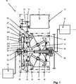
Über einen weiteren, ebenfalls mit F bezeichneten Freilauf
Die Festlegung des Stegs
Auf dem Rücken des Hohlrades
Die Getriebeeingangswelle
Die ausgangsseitige Reibscheibe
Natürlich stellen die in der speziellen Beschreibung diskutierten und in den Figuren gezeigten Ausführungsformen nur illustrative Ausführungsbeispiele der vorliegenden Erfindung dar. Dem Fachmann ist im Lichte der hiesigen Offenbarung ein breites Spektrum an Variationsmöglichkeiten an die Hand gegeben. Insbesondere ist der Fachmann nicht auf den, Einsatz eines Sadivar-Getriebes beschränkt. Andere Arten von Reibrollengetrieben sind ebenfalls einsetzbar. Im Falle der Verwendung eines Minus-Getriebes empfiehlt sich die in
BezugszeichenlisteLIST OF REFERENCE NUMBERS
- 1010
- Pedelec-AntriebsanordnungPedelec drive arrangement
- 1212
- Gehäusecasing
- 1414
- elektrische Maschineelectric machine
- 1616
- Rotorwellerotor shaft
- 1818
- Motorübersetzungs-RadsatzEngine Translation wheel
- 2020
- Getriebe-EingangswelleTransmission input shaft
- 2222
- Reibrollengetriebe/Sadivar-GetriebeTraction roller transmission / gearbox Sadivar
- 2424
- erster Freilauffirst freewheel
- 2626
- zweiter Freilaufsecond freewheel
- 2828
- Planetensatz (Übersetzungsstufe)Planetary gear set (translation stage)
- 281281
- Sonne von
28 (erste Planetensatz-Ausgangswelle)Sun from28 (first planetary gear output shaft) - 282282
- Hohlrad von
28 (Planetensatz-Eingangswelle)Ring gear of28 (Planetary gear input shaft) - 283283
- Steg von
28 (zweite Planetensatz-Ausgangswelle)Footbridge of28 (second planetary gear output shaft) - 284284
- Planetenrad von
28 Planet wheel of28 - 3030
- Tretkurbelwellepedal crankshaft
- 3232
- Tretkurbelcrank
- 3434
- Drucksensorpressure sensor
- 3636
- TrittfrequenzsensorCadence Sensor
- 3838
- WinkellagesensorAngular position sensor
- 4040
- Spreizkupplungexpanding clutch
- 4242
- eingangsseitige Reibscheibeinput-side friction disc
- 4444
- Reibradfriction wheel
- 4646
- ausgangsseitige Reibscheibeoutput friction disk
- 4848
- Aktuatoractuator
- 5050
- Positionssensorposition sensor
- 5252
- Getriebe-AusgangswelleTransmission output shaft
- 5454
- Abtriebsradoutput gear
ZITATE ENTHALTEN IN DER BESCHREIBUNG QUOTES INCLUDE IN THE DESCRIPTION
Diese Liste der vom Anmelder aufgeführten Dokumente wurde automatisiert erzeugt und ist ausschließlich zur besseren Information des Lesers aufgenommen. Die Liste ist nicht Bestandteil der deutschen Patent- bzw. Gebrauchsmusteranmeldung. Das DPMA übernimmt keinerlei Haftung für etwaige Fehler oder Auslassungen.This list of the documents listed by the applicant has been generated automatically and is included solely for the better information of the reader. The list is not part of the German patent or utility model application. The DPMA assumes no liability for any errors or omissions.
Zitierte PatentliteraturCited patent literature
- DE 102014007271 A1[0002]DE 102014007271 A1[0002]
Claims (10)
Translated fromGermanPriority Applications (1)
| Application Number | Priority Date | Filing Date | Title |
|---|---|---|---|
| DE102016203661.0ADE102016203661A1 (en) | 2016-03-07 | 2016-03-07 | Pedelec drive arrangement |
Applications Claiming Priority (1)
| Application Number | Priority Date | Filing Date | Title |
|---|---|---|---|
| DE102016203661.0ADE102016203661A1 (en) | 2016-03-07 | 2016-03-07 | Pedelec drive arrangement |
Publications (1)
| Publication Number | Publication Date |
|---|---|
| DE102016203661A1true DE102016203661A1 (en) | 2017-09-07 |
Family
ID=59651073
Family Applications (1)
| Application Number | Title | Priority Date | Filing Date |
|---|---|---|---|
| DE102016203661.0ACeasedDE102016203661A1 (en) | 2016-03-07 | 2016-03-07 | Pedelec drive arrangement |
Country Status (1)
| Country | Link |
|---|---|
| DE (1) | DE102016203661A1 (en) |
Citations (4)
| Publication number | Priority date | Publication date | Assignee | Title |
|---|---|---|---|---|
| DE102013206710A1 (en)* | 2013-04-15 | 2014-10-16 | Robert Bosch Gmbh | Motor and powered by muscle power vehicle |
| DE102013206713A1 (en)* | 2013-04-15 | 2014-10-16 | Robert Bosch Gmbh | Motor and powered by muscle power vehicle |
| DE102014007271A1 (en) | 2013-06-15 | 2014-12-18 | Peter Strauss | Stepless bottom bracket gearbox for LEVs (Light electric vehicles) with integrated electric motor |
| DE102013015210A1 (en)* | 2013-09-13 | 2015-03-19 | Peter Strauss | Continuously variable transmission especially for bicycles with electric drive |
- 2016
- 2016-03-07DEDE102016203661.0Apatent/DE102016203661A1/ennot_activeCeased
Patent Citations (4)
| Publication number | Priority date | Publication date | Assignee | Title |
|---|---|---|---|---|
| DE102013206710A1 (en)* | 2013-04-15 | 2014-10-16 | Robert Bosch Gmbh | Motor and powered by muscle power vehicle |
| DE102013206713A1 (en)* | 2013-04-15 | 2014-10-16 | Robert Bosch Gmbh | Motor and powered by muscle power vehicle |
| DE102014007271A1 (en) | 2013-06-15 | 2014-12-18 | Peter Strauss | Stepless bottom bracket gearbox for LEVs (Light electric vehicles) with integrated electric motor |
| DE102013015210A1 (en)* | 2013-09-13 | 2015-03-19 | Peter Strauss | Continuously variable transmission especially for bicycles with electric drive |
Similar Documents
| Publication | Publication Date | Title |
|---|---|---|
| EP2986492B1 (en) | Vehicle operable by means of a motor and using muscle power | |
| EP2615022B1 (en) | Drive device for an electric bicycle with force measurement for detection of the rider's intentions | |
| WO2014170061A1 (en) | Vehicle operable by means of a motor and using muscle power | |
| EP3323701B1 (en) | Device for detecting torque, in particular for controlling the additional drive of a vehicle which can be moved by human strength | |
| EP3164326A1 (en) | Drive unit for an electrically assisted bicycle | |
| DE102011089559A1 (en) | Crank drive for bicycle, particularly electric bicycle, has tread shaft for mounting two foot treadles to free ends of tread shaft, driven wheel for power transmission to wheel of bicycle, and planetary gearbox | |
| DE102017126906A1 (en) | Achsrotations torque sensor | |
| DE102008051450A1 (en) | Torque transfer device | |
| DE102011120675A1 (en) | Rotational torque acquisition arrangement for muscle power propelled vehicle e.g. bicycle, has stopper for limiting free travel unit and spring travel of torsion spring element, which is formed between driving wheel and input shaft | |
| EP2566749B1 (en) | Transmission for electrical bicycles for detecting a torque and related method for electrical bicycles for detecting a torque | |
| DE102018101911A1 (en) | Torque detection assembly and gear unit for a muscle powered vehicle | |
| DE102015214935A1 (en) | Electric machine with coupling device and actuating device | |
| DE102017202507A1 (en) | Torque detecting device, drive and working device | |
| DE102014220728A1 (en) | Actuating device with spindle drive and rotary position sensor | |
| DE19609981A1 (en) | Inner bearing unit as torque-rpm sensor system for exercise cycle or ergometer | |
| DE102014209302A1 (en) | Transmission, propulsion kit and windscreen wiper system | |
| DE102019107644A1 (en) | E-axis actuator with bearing of the pinion on the housing and an electric motor actuated axle drive | |
| DE102021210672A1 (en) | Drive arrangement of a two-wheeled vehicle | |
| DE102014221512A1 (en) | Coaxially arranged friction ring gear for a vehicle operable with engine power and / or pedal force | |
| DE102016203661A1 (en) | Pedelec drive arrangement | |
| DE102012208920A1 (en) | Wheel head for axle of e.g. wheeled loader, has wheel gear drivingly connected with shaft end at driving end, where shaft end forms connector socket that is rotatably inserted into drive shaft for coupling wheel hub gear box | |
| DE102019218825A1 (en) | Operating actuator for an automatic transmission as well as automatic transmission with the operating actuator | |
| DE102012018952A1 (en) | Electromechanical steering system mounted in vehicle, has reduction gear whose input side is coupled to electromotor, and converting device that is provided for converting rotating movement to translational movement | |
| DE102010026810A1 (en) | Electrical bicycle, has control device electrically connected to measuring arrangement for controlling electric motor depending on measured quantity, and measuring arrangement comprising deformation sensor | |
| EP4463361B1 (en) | Bicycle drive and bicycle |
Legal Events
| Date | Code | Title | Description |
|---|---|---|---|
| R163 | Identified publications notified | ||
| R012 | Request for examination validly filed | ||
| R082 | Change of representative | Representative=s name:FIEDLER, OSTERMANN & SCHNEIDER - PATENTANWAELT, DE | |
| R082 | Change of representative | ||
| R002 | Refusal decision in examination/registration proceedings | ||
| R003 | Refusal decision now final |