DE102016203637A1 - System and method for using a detected load for a vehicle handling - Google Patents
System and method for using a detected load for a vehicle handlingDownload PDFInfo
- Publication number
- DE102016203637A1 DE102016203637A1DE102016203637.8ADE102016203637ADE102016203637A1DE 102016203637 A1DE102016203637 A1DE 102016203637A1DE 102016203637 ADE102016203637 ADE 102016203637ADE 102016203637 A1DE102016203637 A1DE 102016203637A1
- Authority
- DE
- Germany
- Prior art keywords
- vehicle
- load
- aerodynamic
- tendency
- actuators
- Prior art date
- Legal status (The legal status is an assumption and is not a legal conclusion. Google has not performed a legal analysis and makes no representation as to the accuracy of the status listed.)
- Pending
Links
- 238000000034methodMethods0.000titleclaimsabstractdescription24
- 239000000725suspensionSubstances0.000claimsabstractdescription26
- 230000006641stabilisationEffects0.000claimsdescription12
- 238000011105stabilizationMethods0.000claimsdescription12
- 230000008859changeEffects0.000claimsdescription4
- 230000006399behaviorEffects0.000description6
- 230000006870functionEffects0.000description5
- 230000009467reductionEffects0.000description3
- 230000001133accelerationEffects0.000description2
- 238000009826distributionMethods0.000description2
- 230000005484gravityEffects0.000description2
- BUHVIAUBTBOHAG-FOYDDCNASA-N(2r,3r,4s,5r)-2-[6-[[2-(3,5-dimethoxyphenyl)-2-(2-methylphenyl)ethyl]amino]purin-9-yl]-5-(hydroxymethyl)oxolane-3,4-diolChemical compoundCOC1=CC(OC)=CC(C(CNC=2C=3N=CN(C=3N=CN=2)[C@H]2[C@@H]([C@H](O)[C@@H](CO)O2)O)C=2C(=CC=CC=2)C)=C1BUHVIAUBTBOHAG-FOYDDCNASA-N0.000description1
- 230000004913activationEffects0.000description1
- 238000001994activationMethods0.000description1
- 238000004519manufacturing processMethods0.000description1
- 230000004048modificationEffects0.000description1
- 238000012986modificationMethods0.000description1
- 238000003860storageMethods0.000description1
Images

Classifications
- B—PERFORMING OPERATIONS; TRANSPORTING
- B60—VEHICLES IN GENERAL
- B60G—VEHICLE SUSPENSION ARRANGEMENTS
- B60G17/00—Resilient suspensions having means for adjusting the spring or vibration-damper characteristics, for regulating the distance between a supporting surface and a sprung part of vehicle or for locking suspension during use to meet varying vehicular or surface conditions, e.g. due to speed or load
- B60G17/015—Resilient suspensions having means for adjusting the spring or vibration-damper characteristics, for regulating the distance between a supporting surface and a sprung part of vehicle or for locking suspension during use to meet varying vehicular or surface conditions, e.g. due to speed or load the regulating means comprising electric or electronic elements
- B60G17/016—Resilient suspensions having means for adjusting the spring or vibration-damper characteristics, for regulating the distance between a supporting surface and a sprung part of vehicle or for locking suspension during use to meet varying vehicular or surface conditions, e.g. due to speed or load the regulating means comprising electric or electronic elements characterised by their responsiveness, when the vehicle is travelling, to specific motion, a specific condition, or driver input
- B—PERFORMING OPERATIONS; TRANSPORTING
- B60—VEHICLES IN GENERAL
- B60W—CONJOINT CONTROL OF VEHICLE SUB-UNITS OF DIFFERENT TYPE OR DIFFERENT FUNCTION; CONTROL SYSTEMS SPECIALLY ADAPTED FOR HYBRID VEHICLES; ROAD VEHICLE DRIVE CONTROL SYSTEMS FOR PURPOSES NOT RELATED TO THE CONTROL OF A PARTICULAR SUB-UNIT
- B60W30/00—Purposes of road vehicle drive control systems not related to the control of a particular sub-unit, e.g. of systems using conjoint control of vehicle sub-units
- B60W30/02—Control of vehicle driving stability
- B60W30/045—Improving turning performance
- B—PERFORMING OPERATIONS; TRANSPORTING
- B60—VEHICLES IN GENERAL
- B60G—VEHICLE SUSPENSION ARRANGEMENTS
- B60G17/00—Resilient suspensions having means for adjusting the spring or vibration-damper characteristics, for regulating the distance between a supporting surface and a sprung part of vehicle or for locking suspension during use to meet varying vehicular or surface conditions, e.g. due to speed or load
- B60G17/015—Resilient suspensions having means for adjusting the spring or vibration-damper characteristics, for regulating the distance between a supporting surface and a sprung part of vehicle or for locking suspension during use to meet varying vehicular or surface conditions, e.g. due to speed or load the regulating means comprising electric or electronic elements
- B60G17/016—Resilient suspensions having means for adjusting the spring or vibration-damper characteristics, for regulating the distance between a supporting surface and a sprung part of vehicle or for locking suspension during use to meet varying vehicular or surface conditions, e.g. due to speed or load the regulating means comprising electric or electronic elements characterised by their responsiveness, when the vehicle is travelling, to specific motion, a specific condition, or driver input
- B60G17/0162—Resilient suspensions having means for adjusting the spring or vibration-damper characteristics, for regulating the distance between a supporting surface and a sprung part of vehicle or for locking suspension during use to meet varying vehicular or surface conditions, e.g. due to speed or load the regulating means comprising electric or electronic elements characterised by their responsiveness, when the vehicle is travelling, to specific motion, a specific condition, or driver input mainly during a motion involving steering operation, e.g. cornering, overtaking
- B—PERFORMING OPERATIONS; TRANSPORTING
- B60—VEHICLES IN GENERAL
- B60G—VEHICLE SUSPENSION ARRANGEMENTS
- B60G17/00—Resilient suspensions having means for adjusting the spring or vibration-damper characteristics, for regulating the distance between a supporting surface and a sprung part of vehicle or for locking suspension during use to meet varying vehicular or surface conditions, e.g. due to speed or load
- B60G17/015—Resilient suspensions having means for adjusting the spring or vibration-damper characteristics, for regulating the distance between a supporting surface and a sprung part of vehicle or for locking suspension during use to meet varying vehicular or surface conditions, e.g. due to speed or load the regulating means comprising electric or electronic elements
- B60G17/0195—Resilient suspensions having means for adjusting the spring or vibration-damper characteristics, for regulating the distance between a supporting surface and a sprung part of vehicle or for locking suspension during use to meet varying vehicular or surface conditions, e.g. due to speed or load the regulating means comprising electric or electronic elements characterised by the regulation being combined with other vehicle control systems
- B—PERFORMING OPERATIONS; TRANSPORTING
- B60—VEHICLES IN GENERAL
- B60G—VEHICLE SUSPENSION ARRANGEMENTS
- B60G17/00—Resilient suspensions having means for adjusting the spring or vibration-damper characteristics, for regulating the distance between a supporting surface and a sprung part of vehicle or for locking suspension during use to meet varying vehicular or surface conditions, e.g. due to speed or load
- B60G17/06—Characteristics of dampers, e.g. mechanical dampers
- B60G17/08—Characteristics of fluid dampers
- B—PERFORMING OPERATIONS; TRANSPORTING
- B60—VEHICLES IN GENERAL
- B60T—VEHICLE BRAKE CONTROL SYSTEMS OR PARTS THEREOF; BRAKE CONTROL SYSTEMS OR PARTS THEREOF, IN GENERAL; ARRANGEMENT OF BRAKING ELEMENTS ON VEHICLES IN GENERAL; PORTABLE DEVICES FOR PREVENTING UNWANTED MOVEMENT OF VEHICLES; VEHICLE MODIFICATIONS TO FACILITATE COOLING OF BRAKES
- B60T1/00—Arrangements of braking elements, i.e. of those parts where braking effect occurs specially for vehicles
- B60T1/12—Arrangements of braking elements, i.e. of those parts where braking effect occurs specially for vehicles acting otherwise than by retarding wheels, e.g. jet action
- B60T1/16—Arrangements of braking elements, i.e. of those parts where braking effect occurs specially for vehicles acting otherwise than by retarding wheels, e.g. jet action by increasing air resistance, e.g. flaps
- B—PERFORMING OPERATIONS; TRANSPORTING
- B60—VEHICLES IN GENERAL
- B60W—CONJOINT CONTROL OF VEHICLE SUB-UNITS OF DIFFERENT TYPE OR DIFFERENT FUNCTION; CONTROL SYSTEMS SPECIALLY ADAPTED FOR HYBRID VEHICLES; ROAD VEHICLE DRIVE CONTROL SYSTEMS FOR PURPOSES NOT RELATED TO THE CONTROL OF A PARTICULAR SUB-UNIT
- B60W10/00—Conjoint control of vehicle sub-units of different type or different function
- B60W10/22—Conjoint control of vehicle sub-units of different type or different function including control of suspension systems
- B—PERFORMING OPERATIONS; TRANSPORTING
- B60—VEHICLES IN GENERAL
- B60W—CONJOINT CONTROL OF VEHICLE SUB-UNITS OF DIFFERENT TYPE OR DIFFERENT FUNCTION; CONTROL SYSTEMS SPECIALLY ADAPTED FOR HYBRID VEHICLES; ROAD VEHICLE DRIVE CONTROL SYSTEMS FOR PURPOSES NOT RELATED TO THE CONTROL OF A PARTICULAR SUB-UNIT
- B60W10/00—Conjoint control of vehicle sub-units of different type or different function
- B60W10/30—Conjoint control of vehicle sub-units of different type or different function including control of auxiliary equipment, e.g. air-conditioning compressors or oil pumps
- B—PERFORMING OPERATIONS; TRANSPORTING
- B60—VEHICLES IN GENERAL
- B60W—CONJOINT CONTROL OF VEHICLE SUB-UNITS OF DIFFERENT TYPE OR DIFFERENT FUNCTION; CONTROL SYSTEMS SPECIALLY ADAPTED FOR HYBRID VEHICLES; ROAD VEHICLE DRIVE CONTROL SYSTEMS FOR PURPOSES NOT RELATED TO THE CONTROL OF A PARTICULAR SUB-UNIT
- B60W30/00—Purposes of road vehicle drive control systems not related to the control of a particular sub-unit, e.g. of systems using conjoint control of vehicle sub-units
- B60W30/02—Control of vehicle driving stability
- B—PERFORMING OPERATIONS; TRANSPORTING
- B62—LAND VEHICLES FOR TRAVELLING OTHERWISE THAN ON RAILS
- B62D—MOTOR VEHICLES; TRAILERS
- B62D35/00—Vehicle bodies characterised by streamlining
- B—PERFORMING OPERATIONS; TRANSPORTING
- B62—LAND VEHICLES FOR TRAVELLING OTHERWISE THAN ON RAILS
- B62D—MOTOR VEHICLES; TRAILERS
- B62D37/00—Stabilising vehicle bodies without controlling suspension arrangements
- B62D37/02—Stabilising vehicle bodies without controlling suspension arrangements by aerodynamic means
- B—PERFORMING OPERATIONS; TRANSPORTING
- B60—VEHICLES IN GENERAL
- B60G—VEHICLE SUSPENSION ARRANGEMENTS
- B60G2400/00—Indexing codes relating to detected, measured or calculated conditions or factors
- B60G2400/05—Attitude
- B60G2400/052—Angular rate
- B60G2400/0523—Yaw rate
- B—PERFORMING OPERATIONS; TRANSPORTING
- B60—VEHICLES IN GENERAL
- B60G—VEHICLE SUSPENSION ARRANGEMENTS
- B60G2400/00—Indexing codes relating to detected, measured or calculated conditions or factors
- B60G2400/10—Acceleration; Deceleration
- B60G2400/104—Acceleration; Deceleration lateral or transversal with regard to vehicle
- B—PERFORMING OPERATIONS; TRANSPORTING
- B60—VEHICLES IN GENERAL
- B60G—VEHICLE SUSPENSION ARRANGEMENTS
- B60G2400/00—Indexing codes relating to detected, measured or calculated conditions or factors
- B60G2400/20—Speed
- B60G2400/204—Vehicle speed
- B—PERFORMING OPERATIONS; TRANSPORTING
- B60—VEHICLES IN GENERAL
- B60G—VEHICLE SUSPENSION ARRANGEMENTS
- B60G2400/00—Indexing codes relating to detected, measured or calculated conditions or factors
- B60G2400/40—Steering conditions
- B60G2400/41—Steering angle
- B—PERFORMING OPERATIONS; TRANSPORTING
- B60—VEHICLES IN GENERAL
- B60G—VEHICLE SUSPENSION ARRANGEMENTS
- B60G2400/00—Indexing codes relating to detected, measured or calculated conditions or factors
- B60G2400/50—Pressure
- B60G2400/52—Pressure in tyre
- B—PERFORMING OPERATIONS; TRANSPORTING
- B60—VEHICLES IN GENERAL
- B60G—VEHICLE SUSPENSION ARRANGEMENTS
- B60G2400/00—Indexing codes relating to detected, measured or calculated conditions or factors
- B60G2400/60—Load
- B60G2400/61—Load distribution
- B—PERFORMING OPERATIONS; TRANSPORTING
- B60—VEHICLES IN GENERAL
- B60G—VEHICLE SUSPENSION ARRANGEMENTS
- B60G2400/00—Indexing codes relating to detected, measured or calculated conditions or factors
- B60G2400/60—Load
- B60G2400/63—Location of the center of gravity
- B—PERFORMING OPERATIONS; TRANSPORTING
- B60—VEHICLES IN GENERAL
- B60G—VEHICLE SUSPENSION ARRANGEMENTS
- B60G2500/00—Indexing codes relating to the regulated action or device
- B60G2500/10—Damping action or damper
- B—PERFORMING OPERATIONS; TRANSPORTING
- B60—VEHICLES IN GENERAL
- B60G—VEHICLE SUSPENSION ARRANGEMENTS
- B60G2800/00—Indexing codes relating to the type of movement or to the condition of the vehicle and to the end result to be achieved by the control action
- B60G2800/24—Steering, cornering
- B60G2800/244—Oversteer
- B—PERFORMING OPERATIONS; TRANSPORTING
- B60—VEHICLES IN GENERAL
- B60G—VEHICLE SUSPENSION ARRANGEMENTS
- B60G2800/00—Indexing codes relating to the type of movement or to the condition of the vehicle and to the end result to be achieved by the control action
- B60G2800/24—Steering, cornering
- B60G2800/246—Understeer
- B—PERFORMING OPERATIONS; TRANSPORTING
- B60—VEHICLES IN GENERAL
- B60W—CONJOINT CONTROL OF VEHICLE SUB-UNITS OF DIFFERENT TYPE OR DIFFERENT FUNCTION; CONTROL SYSTEMS SPECIALLY ADAPTED FOR HYBRID VEHICLES; ROAD VEHICLE DRIVE CONTROL SYSTEMS FOR PURPOSES NOT RELATED TO THE CONTROL OF A PARTICULAR SUB-UNIT
- B60W40/00—Estimation or calculation of non-directly measurable driving parameters for road vehicle drive control systems not related to the control of a particular sub unit, e.g. by using mathematical models
- B60W40/12—Estimation or calculation of non-directly measurable driving parameters for road vehicle drive control systems not related to the control of a particular sub unit, e.g. by using mathematical models related to parameters of the vehicle itself, e.g. tyre models
- B60W40/13—Load or weight
- B60W2040/1307—Load distribution on each wheel suspension
- B—PERFORMING OPERATIONS; TRANSPORTING
- B60—VEHICLES IN GENERAL
- B60W—CONJOINT CONTROL OF VEHICLE SUB-UNITS OF DIFFERENT TYPE OR DIFFERENT FUNCTION; CONTROL SYSTEMS SPECIALLY ADAPTED FOR HYBRID VEHICLES; ROAD VEHICLE DRIVE CONTROL SYSTEMS FOR PURPOSES NOT RELATED TO THE CONTROL OF A PARTICULAR SUB-UNIT
- B60W40/00—Estimation or calculation of non-directly measurable driving parameters for road vehicle drive control systems not related to the control of a particular sub unit, e.g. by using mathematical models
- B60W40/12—Estimation or calculation of non-directly measurable driving parameters for road vehicle drive control systems not related to the control of a particular sub unit, e.g. by using mathematical models related to parameters of the vehicle itself, e.g. tyre models
- B60W40/13—Load or weight
- B60W2040/1315—Location of the centre of gravity
- B—PERFORMING OPERATIONS; TRANSPORTING
- B60—VEHICLES IN GENERAL
- B60W—CONJOINT CONTROL OF VEHICLE SUB-UNITS OF DIFFERENT TYPE OR DIFFERENT FUNCTION; CONTROL SYSTEMS SPECIALLY ADAPTED FOR HYBRID VEHICLES; ROAD VEHICLE DRIVE CONTROL SYSTEMS FOR PURPOSES NOT RELATED TO THE CONTROL OF A PARTICULAR SUB-UNIT
- B60W2422/00—Indexing codes relating to the special location or mounting of sensors
- B60W2422/40—Indexing codes relating to the special location or mounting of sensors on a damper
- B—PERFORMING OPERATIONS; TRANSPORTING
- B60—VEHICLES IN GENERAL
- B60W—CONJOINT CONTROL OF VEHICLE SUB-UNITS OF DIFFERENT TYPE OR DIFFERENT FUNCTION; CONTROL SYSTEMS SPECIALLY ADAPTED FOR HYBRID VEHICLES; ROAD VEHICLE DRIVE CONTROL SYSTEMS FOR PURPOSES NOT RELATED TO THE CONTROL OF A PARTICULAR SUB-UNIT
- B60W2422/00—Indexing codes relating to the special location or mounting of sensors
- B60W2422/70—Indexing codes relating to the special location or mounting of sensors on the wheel or the tyre
- B—PERFORMING OPERATIONS; TRANSPORTING
- B60—VEHICLES IN GENERAL
- B60W—CONJOINT CONTROL OF VEHICLE SUB-UNITS OF DIFFERENT TYPE OR DIFFERENT FUNCTION; CONTROL SYSTEMS SPECIALLY ADAPTED FOR HYBRID VEHICLES; ROAD VEHICLE DRIVE CONTROL SYSTEMS FOR PURPOSES NOT RELATED TO THE CONTROL OF A PARTICULAR SUB-UNIT
- B60W2510/00—Input parameters relating to a particular sub-units
- B60W2510/22—Suspension systems
- B—PERFORMING OPERATIONS; TRANSPORTING
- B60—VEHICLES IN GENERAL
- B60W—CONJOINT CONTROL OF VEHICLE SUB-UNITS OF DIFFERENT TYPE OR DIFFERENT FUNCTION; CONTROL SYSTEMS SPECIALLY ADAPTED FOR HYBRID VEHICLES; ROAD VEHICLE DRIVE CONTROL SYSTEMS FOR PURPOSES NOT RELATED TO THE CONTROL OF A PARTICULAR SUB-UNIT
- B60W2520/00—Input parameters relating to overall vehicle dynamics
- B60W2520/10—Longitudinal speed
- B—PERFORMING OPERATIONS; TRANSPORTING
- B60—VEHICLES IN GENERAL
- B60W—CONJOINT CONTROL OF VEHICLE SUB-UNITS OF DIFFERENT TYPE OR DIFFERENT FUNCTION; CONTROL SYSTEMS SPECIALLY ADAPTED FOR HYBRID VEHICLES; ROAD VEHICLE DRIVE CONTROL SYSTEMS FOR PURPOSES NOT RELATED TO THE CONTROL OF A PARTICULAR SUB-UNIT
- B60W2520/00—Input parameters relating to overall vehicle dynamics
- B60W2520/14—Yaw
- B—PERFORMING OPERATIONS; TRANSPORTING
- B60—VEHICLES IN GENERAL
- B60W—CONJOINT CONTROL OF VEHICLE SUB-UNITS OF DIFFERENT TYPE OR DIFFERENT FUNCTION; CONTROL SYSTEMS SPECIALLY ADAPTED FOR HYBRID VEHICLES; ROAD VEHICLE DRIVE CONTROL SYSTEMS FOR PURPOSES NOT RELATED TO THE CONTROL OF A PARTICULAR SUB-UNIT
- B60W2530/00—Input parameters relating to vehicle conditions or values, not covered by groups B60W2510/00 or B60W2520/00
- B60W2530/10—Weight
- B—PERFORMING OPERATIONS; TRANSPORTING
- B60—VEHICLES IN GENERAL
- B60W—CONJOINT CONTROL OF VEHICLE SUB-UNITS OF DIFFERENT TYPE OR DIFFERENT FUNCTION; CONTROL SYSTEMS SPECIALLY ADAPTED FOR HYBRID VEHICLES; ROAD VEHICLE DRIVE CONTROL SYSTEMS FOR PURPOSES NOT RELATED TO THE CONTROL OF A PARTICULAR SUB-UNIT
- B60W2530/00—Input parameters relating to vehicle conditions or values, not covered by groups B60W2510/00 or B60W2520/00
- B60W2530/20—Tyre data
- B—PERFORMING OPERATIONS; TRANSPORTING
- B60—VEHICLES IN GENERAL
- B60W—CONJOINT CONTROL OF VEHICLE SUB-UNITS OF DIFFERENT TYPE OR DIFFERENT FUNCTION; CONTROL SYSTEMS SPECIALLY ADAPTED FOR HYBRID VEHICLES; ROAD VEHICLE DRIVE CONTROL SYSTEMS FOR PURPOSES NOT RELATED TO THE CONTROL OF A PARTICULAR SUB-UNIT
- B60W2540/00—Input parameters relating to occupants
- B60W2540/18—Steering angle
- B—PERFORMING OPERATIONS; TRANSPORTING
- B60—VEHICLES IN GENERAL
- B60W—CONJOINT CONTROL OF VEHICLE SUB-UNITS OF DIFFERENT TYPE OR DIFFERENT FUNCTION; CONTROL SYSTEMS SPECIALLY ADAPTED FOR HYBRID VEHICLES; ROAD VEHICLE DRIVE CONTROL SYSTEMS FOR PURPOSES NOT RELATED TO THE CONTROL OF A PARTICULAR SUB-UNIT
- B60W2556/00—Input parameters relating to data
- B60W2556/10—Historical data
- B—PERFORMING OPERATIONS; TRANSPORTING
- B60—VEHICLES IN GENERAL
- B60W—CONJOINT CONTROL OF VEHICLE SUB-UNITS OF DIFFERENT TYPE OR DIFFERENT FUNCTION; CONTROL SYSTEMS SPECIALLY ADAPTED FOR HYBRID VEHICLES; ROAD VEHICLE DRIVE CONTROL SYSTEMS FOR PURPOSES NOT RELATED TO THE CONTROL OF A PARTICULAR SUB-UNIT
- B60W2710/00—Output or target parameters relating to a particular sub-units
- B60W2710/22—Suspension systems
- B—PERFORMING OPERATIONS; TRANSPORTING
- B60—VEHICLES IN GENERAL
- B60W—CONJOINT CONTROL OF VEHICLE SUB-UNITS OF DIFFERENT TYPE OR DIFFERENT FUNCTION; CONTROL SYSTEMS SPECIALLY ADAPTED FOR HYBRID VEHICLES; ROAD VEHICLE DRIVE CONTROL SYSTEMS FOR PURPOSES NOT RELATED TO THE CONTROL OF A PARTICULAR SUB-UNIT
- B60W2710/00—Output or target parameters relating to a particular sub-units
- B60W2710/30—Auxiliary equipments
- B—PERFORMING OPERATIONS; TRANSPORTING
- B60—VEHICLES IN GENERAL
- B60W—CONJOINT CONTROL OF VEHICLE SUB-UNITS OF DIFFERENT TYPE OR DIFFERENT FUNCTION; CONTROL SYSTEMS SPECIALLY ADAPTED FOR HYBRID VEHICLES; ROAD VEHICLE DRIVE CONTROL SYSTEMS FOR PURPOSES NOT RELATED TO THE CONTROL OF A PARTICULAR SUB-UNIT
- B60W2900/00—Indexing codes relating to the purpose of, or problem solved of road vehicle drive control systems not otherwise provided for in groups B60W30/00
- B—PERFORMING OPERATIONS; TRANSPORTING
- B61—RAILWAYS
- B61H—BRAKES OR OTHER RETARDING DEVICES SPECIALLY ADAPTED FOR RAIL VEHICLES; ARRANGEMENT OR DISPOSITION THEREOF IN RAIL VEHICLES
- B61H11/00—Applications or arrangements of braking or retarding apparatus not otherwise provided for; Combinations of apparatus of different kinds or types
- B61H11/06—Applications or arrangements of braking or retarding apparatus not otherwise provided for; Combinations of apparatus of different kinds or types of hydrostatic, hydrodynamic, or aerodynamic brakes
- B61H11/10—Aerodynamic brakes with control flaps, e.g. spoilers, attached to the vehicles
- Y—GENERAL TAGGING OF NEW TECHNOLOGICAL DEVELOPMENTS; GENERAL TAGGING OF CROSS-SECTIONAL TECHNOLOGIES SPANNING OVER SEVERAL SECTIONS OF THE IPC; TECHNICAL SUBJECTS COVERED BY FORMER USPC CROSS-REFERENCE ART COLLECTIONS [XRACs] AND DIGESTS
- Y02—TECHNOLOGIES OR APPLICATIONS FOR MITIGATION OR ADAPTATION AGAINST CLIMATE CHANGE
- Y02T—CLIMATE CHANGE MITIGATION TECHNOLOGIES RELATED TO TRANSPORTATION
- Y02T10/00—Road transport of goods or passengers
- Y02T10/80—Technologies aiming to reduce greenhouse gasses emissions common to all road transportation technologies
- Y02T10/88—Optimized components or subsystems, e.g. lighting, actively controlled glasses
Landscapes
- Engineering & Computer Science (AREA)
- Mechanical Engineering (AREA)
- Transportation (AREA)
- Automation & Control Theory (AREA)
- Chemical & Material Sciences (AREA)
- Combustion & Propulsion (AREA)
- Physics & Mathematics (AREA)
- Fluid Mechanics (AREA)
- Vehicle Body Suspensions (AREA)
- Control Of Driving Devices And Active Controlling Of Vehicle (AREA)
Abstract
Translated fromGermanDescription
Translated fromGermanGebietarea
Die Erfindung betrifft das Handling eines Passagierfahrzeuges, und insbesondere ein System und ein Verfahren zur dynamischen Änderung einer auf das Fahrzeug wirkenden Last oder der Fahrzeugfederung, um Übersteuerungs- oder Untersteuerungs-Neigungen zu verringern.The invention relates to the handling of a passenger vehicle, and more particularly to a system and method for dynamically changing a load on the vehicle or the vehicle suspension to reduce oversteer or understeer slopes.
Hintergrundbackground
Moderne Kraftfahrzeuge sind oftmals mit einem Fahrzeugdynamik-Steuersystem ausgestattet, wie zum Beispiel dem bekannten ESC(Elektronische Stabilitätssteuerung)-System, welches das Fahrzeug in kritischen Fahrsituationen stabilisiert. Zu diesem Zweck wird die Bremskraft gewöhnlicherweise gezielt an einzelnen Rädern des Fahrzeuges erhöht, um ein Giermoment zu erzeugen, welches das Fahrzeug stabilisiert. Jedoch kann der Bremseingriff, der insbesondere vom ESC-System vorgenommen wird, vom Fahrer deutlich als eine Fahrzeugverzögerung wahrgenommen werden, weshalb der Eingriff unerwartet und unkomfortabel sein kann. Außerdem reagiert das ESC-System typischerweise nach Auftreten der Instabilität.Modern motor vehicles are often equipped with a vehicle dynamics control system, such as the well-known ESC (Electronic Stability Control) system, which stabilizes the vehicle in critical driving situations. For this purpose, the braking force is usually increased selectively on individual wheels of the vehicle to produce a yaw moment which stabilizes the vehicle. However, the braking intervention, which is particularly made by the ESC system, can be clearly perceived by the driver as a vehicle deceleration, so the intervention can be unexpected and uncomfortable. In addition, the ESC system typically responds after the occurrence of instability.
Somit besteht ein Bedarf, ein System und ein Verfahren bereitzustellen, welche die Last auf das Fahrzeug oder die Federungshärte dynamisch ändern, um Übersteuerungs- oder Untersteuerungs-Neigungen auf Basis einer Fahrzeuglastinformation zusammen mit anderen Fahrzeuginformationen vor Auftreten einer Instabilität zu reduzieren.Thus, there is a need to provide a system and method that dynamically changes the load on the vehicle or the suspension stiffness to reduce oversteer or understeer tendencies based on vehicle load information along with other vehicle information prior to the occurrence of instability.
ZusammenfassungSummary
Eine Aufgabe der Erfindung besteht in der Lösung des oben aufgeführten Problems. In Übereinstimmung mit den Prinzipien einer Ausführungsform wird diese Aufgabe durch Bereitstellen eines Verfahrens zum Steuern einer Fahrbarkeit eines Fahrzeuges gelöst. Das Verfahren erfasst eine auf das Fahrzeug wirkende Gesamtlast. Eine Masse des Fahrzeuges oder ein Schätzwert davon wird bezogen. Eine Steuerung stellt eine Kurvenfahrt des Fahrzeugs fest. Falls das Fahrzeug in einer Kurve fährt, bestimmt die Steuerung, ob das Fahrzeug eine Neigung zum Übersteuern oder zum Untersteuern aufweist. Die auf das Fahrzeug wirkende Last wird dynamisch geändert oder es wird eine Federungshärte des Fahrzeuges dynamisch angepasst, um die Neigung des Fahrzeuges zum Über- oder Untersteuern zu verringern.An object of the invention is to solve the above problem. In accordance with the principles of one embodiment, this object is achieved by providing a method for controlling driveability of a vehicle. The method detects a total load acting on the vehicle. A mass of the vehicle or an estimate thereof is obtained. A controller determines a cornering of the vehicle. If the vehicle is turning, the controller determines whether the vehicle is oversteer or understeer. The load applied to the vehicle is changed dynamically or a suspension stiffness of the vehicle is dynamically adjusted to reduce the tendency of the vehicle to oversteer or understeer.
In Übereinstimmung mit einem weiteren Aspekt einer Ausführungsform umfasst ein Fahrstabilitäts-Steuerungssystem für ein Fahrzeug eine Fahrzeuglast-Sensorstruktur, die dazu ausgebildet und angeordnet ist, um eine auf ein Fahrzeug wirkende Gesamtlast zu beziehen. Eine Fahrzeuginformation-Sensorstruktur ist dazu ausgebildet und angeordnet, um eine Fahrzeuginformation einschließlich wenigstens einer Gier- und Lenk-Information des Fahrzeuges zu beziehen. Erste Aktuatoren sind derart ausgebildet und angeordnet, um Aerodynamik-Komponenten des Fahrzeuges zu steuern. Zweite Aktuatoren sind derart ausgebildet und angeordnet, um eine Federung des Fahrzeuges zu steuern. Eine Fahrzeugverhalten-Steuerung ist derart ausgebildet und angeordnet, um die Fahrzeuginformation und die auf das Fahrzeug wirkende Gesamtlast zu empfangen und basierend darauf ein Signal an die ersten Aktuatoren zu senden, um die Aerodynamik-Komponenten dynamisch anzupassen, um eine Last auf das Fahrzeug zu ändern, oder um ein Signal an die zweiten Aktuatoren zu senden, um die Federung des Fahrzeuges dynamisch anzupassen, um eine Neigung des Fahrzeuges zum Über- oder Untersteuern zu reduzieren.In accordance with another aspect of an embodiment, a vehicle stability control system for a vehicle includes a vehicle load sensor structure configured and arranged to acquire a total load on a vehicle. A vehicle information sensor structure is configured and arranged to receive vehicle information including at least yaw and steering information of the vehicle. First actuators are configured and arranged to control aerodynamic components of the vehicle. Second actuators are configured and arranged to control a suspension of the vehicle. A vehicle behavior controller is configured and arranged to receive the vehicle information and the total load applied to the vehicle and, based thereon, send a signal to the first actuators to dynamically adjust the aerodynamic components to change a load on the vehicle or to send a signal to the second actuators to dynamically adjust the suspension of the vehicle to reduce the vehicle's tendency to oversteer or understeer.
Weitere Gegenstände, Merkmale und Eigenschaften der vorliegenden Erfindung, als auch die Verfahren zum Betreiben und die Funktionen der entsprechenden Elemente der Struktur, die Kombination von Teilen und die vereinfachte Herstellung werden bei Betrachtung der folgenden detaillierten Beschreibung und den beigefügten Ansprüchen mit Bezug auf die begleitenden Zeichnung verständlicher werden, die alle einen Teil dieser Beschreibung bilden.Other objects, features and characteristics of the present invention as well as the methods of operation and the functions of the corresponding elements of the structure, the combination of parts and the simplified manufacture will become apparent upon consideration of the following detailed description and the appended claims with reference to the accompanying drawings become more comprehensible, all of which form part of this description.
Kurze Beschreibung der ZeichnungenBrief description of the drawings
Die Erfindung wird aus der folgenden detaillierten Beschreibung der bevorzugten Ausführungsformen davon in Verbindung mit den begleitenden Zeichnungen besser verständlich, wobei gleiche Bezugszeichen gleiche Komponenten kennzeichnen, wobei:The invention will be better understood from the following detailed description of the preferred embodiments thereof, taken in conjunction with the accompanying drawings, wherein like reference numerals designate like components, wherein:
Detaillierte Beschreibung der beispielhaften Ausführungsformen Detailed Description of the Exemplary Embodiments
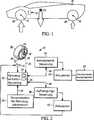
Mit Bezug auf
Die Steuerung
Alternativ kann die Fahrzeuglast durch das elektronische Reifeninformationssystem (eTIS) von Continental bezogen werden, welches einen direkt in die innere Lage des Reifens jedes Rads
Mit Bezug auf
Wiederum mit Bezug auf
Somit beinhaltet das System
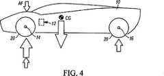
Mit Bezug auf
Falls das Fahrzeug eine Kurve durchfährt, dann bestimmt der Prozessorschaltkreis
Während das Fahrzeug eine Kurve durchfährt und falls keine Übersteuerungsneigung vorliegt, bestimmt der Prozessorschaltkreis
Alle Anpassungen zur Verringerung der Untersteuerungs- bzw. Übersteuerungsneigung finden dynamisch in Echtzeit statt, mit dem Ziel, die Kurvenfahrteigenschaften des Fahrzeuges
Die hierin beschriebenen Funktionen und Algorithmen können als ein ausführbarer Code in dem Steuerung
Die vorangegangenen bevorzugten Ausführungsformen wurden für Zwecke der Darstellung der strukturellen und funktionalen Prinzipien der vorliegenden Erfindung dargestellt und beschrieben, als auch zur Darstellung der Verfahren des Anwendens der bevorzugten Ausführungsformen, wobei diese änderbar sind, ohne von diesen Prinzipien abzukehren. Deshalb beinhaltet diese Erfindung alle im Umfang der folgenden Ansprüche liegenden Modifikationen.The foregoing preferred embodiments have been illustrated and described for purposes of illustrating the structural and functional principles of the present invention, as well as illustrating the methods of employing the preferred embodiments, which are alterable without departing from such principles. Therefore, this invention includes all modifications within the scope of the following claims.
ZITATE ENTHALTEN IN DER BESCHREIBUNG QUOTES INCLUDE IN THE DESCRIPTION
Diese Liste der vom Anmelder aufgeführten Dokumente wurde automatisiert erzeugt und ist ausschließlich zur besseren Information des Lesers aufgenommen. Die Liste ist nicht Bestandteil der deutschen Patent- bzw. Gebrauchsmusteranmeldung. Das DPMA übernimmt keinerlei Haftung für etwaige Fehler oder Auslassungen.This list of the documents listed by the applicant has been generated automatically and is included solely for the better information of the reader. The list is not part of the German patent or utility model application. The DPMA assumes no liability for any errors or omissions.
Zitierte PatentliteraturCited patent literature
- US 8395491 B2[0016]US 8395491 B2[0016]
Claims (19)
Translated fromGermanApplications Claiming Priority (2)
| Application Number | Priority Date | Filing Date | Title |
|---|---|---|---|
| US14/661,041 | 2015-03-18 | ||
| US14/661,041US9573591B2 (en) | 2015-03-18 | 2015-03-18 | System and method utilizing detected load for vehicle handling |
Publications (1)
| Publication Number | Publication Date |
|---|---|
| DE102016203637A1true DE102016203637A1 (en) | 2016-09-22 |
Family
ID=55952304
Family Applications (1)
| Application Number | Title | Priority Date | Filing Date |
|---|---|---|---|
| DE102016203637.8APendingDE102016203637A1 (en) | 2015-03-18 | 2016-03-07 | System and method for using a detected load for a vehicle handling |
Country Status (5)
| Country | Link |
|---|---|
| US (1) | US9573591B2 (en) |
| JP (1) | JP2016175639A (en) |
| DE (1) | DE102016203637A1 (en) |
| FR (1) | FR3033756B1 (en) |
| GB (2) | GB2538356B (en) |
Cited By (2)
| Publication number | Priority date | Publication date | Assignee | Title |
|---|---|---|---|---|
| DE102017126884A1 (en)* | 2017-11-15 | 2019-05-16 | Michael Benn Rothschild | A digital hardware-based system and method for preventing the initial onset of trailer vibrations and the control thereof |
| DE102024103891A1 (en)* | 2023-12-22 | 2025-06-26 | GM Global Technology Operations LLC | VEHICLE WHEEL FORCE CONTROL SYSTEMS |
Families Citing this family (11)
| Publication number | Priority date | Publication date | Assignee | Title |
|---|---|---|---|---|
| KR101766027B1 (en)* | 2015-08-21 | 2017-08-07 | 현대자동차주식회사 | Balance Maintain Apparatus and Control Method Of Vehicle |
| US10065688B2 (en)* | 2015-09-25 | 2018-09-04 | GM Global Technology Operations LLC | Vehicle, system, and method for controlling active aerodynamic elements |
| US9975391B2 (en)* | 2015-10-22 | 2018-05-22 | Ford Global Technologies, Llc | Vehicle handling dynamics control using fully active suspension |
| US20180022403A1 (en)* | 2016-07-20 | 2018-01-25 | GM Global Technology Operations LLC | Method for controlling vehicle downforce |
| GB2558570B (en) | 2017-01-05 | 2021-12-29 | Mclaren Automotive Ltd | Damper control |
| EP3681773B1 (en)* | 2017-09-14 | 2023-11-22 | Volvo Truck Corporation | A method/device for improving braking performance on wheeled vehicle |
| US10618573B2 (en)* | 2017-10-16 | 2020-04-14 | GM Global Technology Operations LLC | System and method for controlling an active aerodynamic member |
| US20190263458A1 (en)* | 2018-02-28 | 2019-08-29 | GM Global Technology Operations LLC | Methods and systems for active aerodynamic balance |
| CN110422166B (en)* | 2019-08-02 | 2020-09-01 | 上海振华重工(集团)股份有限公司 | Anti-overturn stability control system and method for straddle carrier |
| DE102020205702B3 (en)* | 2020-05-06 | 2021-09-02 | Volkswagen Aktiengesellschaft | Driving dynamics control of a vehicle by means of dampers |
| CN119116614A (en)* | 2023-06-12 | 2024-12-13 | 本田技研工业株式会社 | Control device and method of variable damping force damper |
Citations (1)
| Publication number | Priority date | Publication date | Assignee | Title |
|---|---|---|---|---|
| US8395491B2 (en) | 2001-06-13 | 2013-03-12 | Continental Teves Ag & Co. Ohg | Method for controlling driving stability |
Family Cites Families (59)
| Publication number | Priority date | Publication date | Assignee | Title |
|---|---|---|---|---|
| DE3810638C1 (en) | 1988-03-29 | 1989-08-10 | Boge Ag, 5208 Eitorf, De | |
| JP2768015B2 (en) | 1991-01-29 | 1998-06-25 | 日産自動車株式会社 | Active suspension |
| DE4229504B4 (en)* | 1992-09-04 | 2007-11-29 | Robert Bosch Gmbh | Method for regulating vehicle stability |
| JP3443846B2 (en)* | 1992-09-11 | 2003-09-08 | マツダ株式会社 | Driving feeling control device |
| US5711024A (en)* | 1994-11-25 | 1998-01-20 | Itt Automotive Europe Gmbh | System for controlling yaw moment based on an estimated coefficient of friction |
| US6125319A (en)* | 1998-08-17 | 2000-09-26 | General Motors Corporation | Brake system control method responsive to measured vehicle acceleration |
| JP4042277B2 (en)* | 1999-11-29 | 2008-02-06 | アイシン精機株式会社 | Vehicle side slip angle estimation device |
| US6505108B2 (en) | 2000-03-01 | 2003-01-07 | Delphi Technologies, Inc. | Damper based vehicle yaw control |
| DE10014220A1 (en)* | 2000-03-22 | 2001-09-27 | Bosch Gmbh Robert | Transverse acceleration determination method for vehicle, involves obtaining load signal along with wheel speed signal and calculating gravity center height with transverse acceleration using specific algorithm |
| US7676307B2 (en)* | 2001-11-05 | 2010-03-09 | Ford Global Technologies | System and method for controlling a safety system of a vehicle in response to conditions sensed by tire sensors related applications |
| JP3997819B2 (en)* | 2002-02-18 | 2007-10-24 | トヨタ自動車株式会社 | Tire condition acquisition device |
| US20040024505A1 (en)* | 2002-08-05 | 2004-02-05 | Salib Albert Chenouda | System and method for operating a rollover control system in a transition to a rollover condition |
| US20040024504A1 (en)* | 2002-08-05 | 2004-02-05 | Salib Albert Chenouda | System and method for operating a rollover control system during an elevated condition |
| JP3781114B2 (en)* | 2002-08-07 | 2006-05-31 | トヨタ自動車株式会社 | Vehicle ground load control device |
| JP3990623B2 (en)* | 2002-11-19 | 2007-10-17 | 富士重工業株式会社 | Vehicle behavior control device |
| JP3975922B2 (en)* | 2003-01-17 | 2007-09-12 | トヨタ自動車株式会社 | Curve radius estimation device |
| JP2005081998A (en)* | 2003-09-08 | 2005-03-31 | Toyota Motor Corp | Steering characteristic control device |
| US7647148B2 (en)* | 2003-12-12 | 2010-01-12 | Ford Global Technologies, Llc | Roll stability control system for an automotive vehicle using coordinated control of anti-roll bar and brakes |
| US7222007B2 (en)* | 2004-01-07 | 2007-05-22 | Ford Global Technologies, Llc | Attitude sensing system for an automotive vehicle relative to the road |
| JP2005238992A (en)* | 2004-02-26 | 2005-09-08 | Hitachi Ltd | Vehicle control device |
| US20050206231A1 (en)* | 2004-03-18 | 2005-09-22 | Ford Global Technologies, Llc | Method and apparatus for controlling an automotive vehicle using brake-steer and normal load adjustment |
| JP4267495B2 (en)* | 2004-03-31 | 2009-05-27 | 本田技研工業株式会社 | Driving force control method for four-wheel drive vehicle |
| DE102004035004A1 (en)* | 2004-07-20 | 2006-02-16 | Bayerische Motoren Werke Ag | Method for increasing the driving stability of a motor vehicle |
| US7640081B2 (en)* | 2004-10-01 | 2009-12-29 | Ford Global Technologies, Llc | Roll stability control using four-wheel drive |
| US7826948B2 (en)* | 2004-10-15 | 2010-11-02 | Ford Global Technologies | Vehicle loading based vehicle dynamic and safety related characteristic adjusting system |
| WO2006091667A1 (en)* | 2005-02-22 | 2006-08-31 | Kelsey-Hayes Company | Vehicle stability control utilizing static tire data |
| US7561951B2 (en)* | 2005-05-06 | 2009-07-14 | Ford Global Technologies Llc | Occupant control system integrated with vehicle dynamics controls |
| JP4631549B2 (en)* | 2005-06-01 | 2011-02-16 | 株式会社アドヴィックス | Vehicle motion stabilization control device |
| US7386379B2 (en)* | 2005-07-22 | 2008-06-10 | Gm Global Technology Operations, Inc. | Method and apparatus to control coordinated wheel motors |
| JP2007191085A (en)* | 2006-01-20 | 2007-08-02 | Toyota Motor Corp | Vehicle rectifier |
| US7558661B2 (en)* | 2006-05-02 | 2009-07-07 | Delphi Technologies, Inc. | Adaptive maneuver based diagnostics for vehicle dynamics |
| US7970512B2 (en)* | 2006-08-30 | 2011-06-28 | Ford Global Technologies | Integrated control system for stability control of yaw, roll and lateral motion of a driving vehicle using an integrated sensing system with pitch information |
| US8321088B2 (en)* | 2006-08-30 | 2012-11-27 | Ford Global Technologies | Integrated control system for stability control of yaw, roll and lateral motion of a driving vehicle using an integrated sensing system to determine lateral velocity |
| US8712639B2 (en)* | 2006-08-30 | 2014-04-29 | Ford Global Technologies | Integrated control system for stability control of yaw, roll and lateral motion of a driving vehicle using an integrated sensing system to determine longitudinal velocity |
| US7885750B2 (en)* | 2006-08-30 | 2011-02-08 | Ford Global Technologies | Integrated control system for stability control of yaw, roll and lateral motion of a driving vehicle using an integrated sensing system to determine a sideslip angle |
| US7739014B2 (en)* | 2006-08-30 | 2010-06-15 | Ford Global Technolgies | Integrated control system for stability control of yaw, roll and lateral motion of a driving vehicle using an integrated sensing system to determine a final linear lateral velocity |
| US7493199B2 (en)* | 2006-10-17 | 2009-02-17 | Trw Automotive U.S. Llc | Method of controlling a roll control system for improved vehicle dynamic control |
| JP2010516556A (en)* | 2007-01-25 | 2010-05-20 | 本田技研工業株式会社 | Vehicle system control method for improving vehicle stability |
| US7848864B2 (en)* | 2007-05-07 | 2010-12-07 | Gm Global Technology Operations, Inc. | System for estimating vehicle states for rollover reduction |
| US20090187324A1 (en)* | 2008-01-23 | 2009-07-23 | Jianbo Lu | Vehicle Stability Control System and Method |
| DE102008046269B3 (en)* | 2008-09-08 | 2009-12-24 | Continental Automotive Gmbh | Wheel load determining method for passenger car, involves comparing calculated wheel load with detected wheel load, and performing adaptation of equations and/or equation parameters based on comparison |
| WO2010030158A1 (en) | 2008-09-10 | 2010-03-18 | Ting Kuok Wong | Automatic adjustable vehicle spoiler system |
| JP5113098B2 (en)* | 2009-01-23 | 2013-01-09 | 日立オートモティブシステムズ株式会社 | Vehicle rollover prevention control device and vehicle rollover prevention control method |
| US7770962B1 (en)* | 2009-04-13 | 2010-08-10 | Maxwell John B | Dynamic automobile wing |
| JPWO2010134251A1 (en)* | 2009-05-21 | 2012-11-08 | アイシン精機株式会社 | Vehicle ground load control device |
| US8670909B2 (en)* | 2009-07-14 | 2014-03-11 | Ford Global Technologies, Llc | Automotive vehicle |
| JP2011251592A (en)* | 2010-05-31 | 2011-12-15 | Equos Research Co Ltd | Vehicle control system |
| DE102010026432A1 (en)* | 2010-07-08 | 2012-01-12 | Jürgen Rothenbücher | Driving assistance device for vehicle, has aerodynamic driving aid which is adjustable according to detection result of travel path detecting device |
| US8313108B2 (en)* | 2010-07-22 | 2012-11-20 | GM Global Technology Operations LLC | Stiffness control using smart actuators |
| JP5126320B2 (en)* | 2010-08-30 | 2013-01-23 | トヨタ自動車株式会社 | Vehicle control device |
| JP5571519B2 (en)* | 2010-09-27 | 2014-08-13 | 日立オートモティブシステムズ株式会社 | Body posture control device |
| US8626389B2 (en)* | 2010-10-28 | 2014-01-07 | GM Global Technology Operations LLC | Method and system for determining a reference yaw rate for a vehicle |
| US9073576B2 (en)* | 2011-09-02 | 2015-07-07 | GM Global Technology Operations LLC | System and method for smooth steering override transition during automated lane centering |
| WO2013100121A1 (en)* | 2011-12-28 | 2013-07-04 | 日産自動車株式会社 | Vehicle control device |
| ITBO20120089A1 (en) | 2012-02-24 | 2013-08-25 | Ferrari Spa | METHOD OF CONTROL OF A HIGH PERFORMANCE ROAD VEHICLE PROVIDED WITH A REAR BULB WITH AT LEAST ONE MOBILE WING ELEMENT |
| US9567003B2 (en)* | 2012-11-07 | 2017-02-14 | Nissan Motor Co., Ltd. | Steering control device |
| US8825293B2 (en)* | 2013-01-04 | 2014-09-02 | Ford Global Technologies, Llc | Suspension control for pulse/glide green cruise control |
| JP6275416B2 (en)* | 2013-08-30 | 2018-02-07 | 日立オートモティブシステムズ株式会社 | Vehicle behavior control device |
| GB2527526B (en)* | 2014-06-24 | 2017-12-06 | Jaguar Land Rover Ltd | Controlling the stability of a vehicle |
- 2015
- 2015-03-18USUS14/661,041patent/US9573591B2/enactiveActive
- 2016
- 2016-03-07DEDE102016203637.8Apatent/DE102016203637A1/enactivePending
- 2016-03-08FRFR1600391Apatent/FR3033756B1/enactiveActive
- 2016-03-14GBGB1604338.2Apatent/GB2538356B/enactiveActive
- 2016-03-14GBGB1810102.2Apatent/GB2560846B/enactiveActive
- 2016-03-18JPJP2016054921Apatent/JP2016175639A/enactivePending
Patent Citations (1)
| Publication number | Priority date | Publication date | Assignee | Title |
|---|---|---|---|---|
| US8395491B2 (en) | 2001-06-13 | 2013-03-12 | Continental Teves Ag & Co. Ohg | Method for controlling driving stability |
Cited By (3)
| Publication number | Priority date | Publication date | Assignee | Title |
|---|---|---|---|---|
| DE102017126884A1 (en)* | 2017-11-15 | 2019-05-16 | Michael Benn Rothschild | A digital hardware-based system and method for preventing the initial onset of trailer vibrations and the control thereof |
| DE102017126884B4 (en) | 2017-11-15 | 2023-10-05 | Michael Benn Rothschild | Digital hardware-based system and method for preventing the initial onset of vibration of a trailer and controlling the same |
| DE102024103891A1 (en)* | 2023-12-22 | 2025-06-26 | GM Global Technology Operations LLC | VEHICLE WHEEL FORCE CONTROL SYSTEMS |
Also Published As
| Publication number | Publication date |
|---|---|
| US20160272198A1 (en) | 2016-09-22 |
| US9573591B2 (en) | 2017-02-21 |
| GB2538356B (en) | 2018-08-01 |
| FR3033756A1 (en) | 2016-09-23 |
| GB2538356A (en) | 2016-11-16 |
| FR3033756B1 (en) | 2019-06-07 |
| GB201604338D0 (en) | 2016-04-27 |
| GB2560846A (en) | 2018-09-26 |
| GB201810102D0 (en) | 2018-08-08 |
| GB2560846B (en) | 2019-05-22 |
| JP2016175639A (en) | 2016-10-06 |
Similar Documents
| Publication | Publication Date | Title |
|---|---|---|
| DE102016203637A1 (en) | System and method for using a detected load for a vehicle handling | |
| EP1197409B1 (en) | Vehicle dynamics control method | |
| DE102008045261B9 (en) | Method and device for vehicle stability control by the targeted influencing of tire force vectors | |
| EP2233332B1 (en) | Method for controlling actuators which affect the roll angle of a motor vehicle | |
| WO2005087521A1 (en) | Method for regulating the driving dynamics of a vehicle, device for carrying out the method and use thereof | |
| DE102014218760A1 (en) | Suspension system | |
| EP1030798A1 (en) | Method and device for stabilising motor vehicle tilt | |
| WO2007054500A1 (en) | Method and device for stabilizing a motor vehicle | |
| EP2965930B1 (en) | Control device for a pressurised air assembly of a commercial vehicle | |
| DE102008053008A1 (en) | Method and system for influencing the movement of a controllable in his movements vehicle structure of a motor vehicle and vehicle | |
| DE112018005542T5 (en) | Vehicle control system | |
| WO2007118587A2 (en) | System for influencing the driving behaviour of a vehicle | |
| DE102016013189A1 (en) | Device for controlling vehicle behavior | |
| DE102005013807B4 (en) | Method for controlling a vehicle and integrated vehicle control system | |
| DE102015221833A1 (en) | Vehicle load information system for determining a rake and a load when attached to the vehicle trailer | |
| DE102017112290A1 (en) | DYNAMIC REAL-TIME SYSTEM FOR STABILITY CONTROL BY THE DRIVER | |
| DE102012222489A1 (en) | Method for controlling the driving dynamics | |
| DE112020004640T5 (en) | vehicle motion control device | |
| WO2007118588A1 (en) | Method and device for controlling the driving behavior of a motor vehicle | |
| DE102004008265A1 (en) | Control method for a motor vehicle's wheel drift control system uses a wheel drift/slippage controller to generate adjustment variables for individual wheels | |
| DE112021004306T5 (en) | SUSPENSION CONTROL DEVICE, VEHICLE AND SUSPENSION CONTROL METHOD | |
| EP2052884B1 (en) | Method and system for affecting the movement of a vehicle structure on a powered vehicle and vehicle controlled or regulated by its movement processes | |
| DE10329278A1 (en) | Stabilizer, vehicle equipped with it and stabilization method | |
| DE102018204606B4 (en) | suspension control system | |
| DE19909453A1 (en) | Method of improving the driving behavior of a vehicle when driving on a curved path with a change in vehicle dynamic behavior especially engine torque |
Legal Events
| Date | Code | Title | Description |
|---|---|---|---|
| R012 | Request for examination validly filed | ||
| R082 | Change of representative | Representative=s name:BRAND, MARKUS, DIPL.-PHYS. DR. PHIL. NAT., DE | |
| R016 | Response to examination communication |