DE102016203518A1 - Connecting device of a medical infusion system - Google Patents
Connecting device of a medical infusion systemDownload PDFInfo
- Publication number
- DE102016203518A1 DE102016203518A1DE102016203518.5ADE102016203518ADE102016203518A1DE 102016203518 A1DE102016203518 A1DE 102016203518A1DE 102016203518 ADE102016203518 ADE 102016203518ADE 102016203518 A1DE102016203518 A1DE 102016203518A1
- Authority
- DE
- Germany
- Prior art keywords
- valve body
- connecting device
- valve
- connecting piece
- bottom ring
- Prior art date
- Legal status (The legal status is an assumption and is not a legal conclusion. Google has not performed a legal analysis and makes no representation as to the accuracy of the status listed.)
- Withdrawn
Links
Images


Classifications
- A—HUMAN NECESSITIES
- A61—MEDICAL OR VETERINARY SCIENCE; HYGIENE
- A61M—DEVICES FOR INTRODUCING MEDIA INTO, OR ONTO, THE BODY; DEVICES FOR TRANSDUCING BODY MEDIA OR FOR TAKING MEDIA FROM THE BODY; DEVICES FOR PRODUCING OR ENDING SLEEP OR STUPOR
- A61M39/00—Tubes, tube connectors, tube couplings, valves, access sites or the like, specially adapted for medical use
- A61M39/02—Access sites
- A61M39/04—Access sites having pierceable self-sealing members
- A61M39/045—Access sites having pierceable self-sealing members pre-slit to be pierced by blunt instrument
- A—HUMAN NECESSITIES
- A61—MEDICAL OR VETERINARY SCIENCE; HYGIENE
- A61M—DEVICES FOR INTRODUCING MEDIA INTO, OR ONTO, THE BODY; DEVICES FOR TRANSDUCING BODY MEDIA OR FOR TAKING MEDIA FROM THE BODY; DEVICES FOR PRODUCING OR ENDING SLEEP OR STUPOR
- A61M39/00—Tubes, tube connectors, tube couplings, valves, access sites or the like, specially adapted for medical use
- A61M39/22—Valves or arrangement of valves
- A—HUMAN NECESSITIES
- A61—MEDICAL OR VETERINARY SCIENCE; HYGIENE
- A61M—DEVICES FOR INTRODUCING MEDIA INTO, OR ONTO, THE BODY; DEVICES FOR TRANSDUCING BODY MEDIA OR FOR TAKING MEDIA FROM THE BODY; DEVICES FOR PRODUCING OR ENDING SLEEP OR STUPOR
- A61M39/00—Tubes, tube connectors, tube couplings, valves, access sites or the like, specially adapted for medical use
- A61M39/10—Tube connectors; Tube couplings
- A61M39/16—Tube connectors; Tube couplings having provision for disinfection or sterilisation
- A61M39/18—Methods or apparatus for making the connection under sterile conditions, i.e. sterile docking
- A—HUMAN NECESSITIES
- A61—MEDICAL OR VETERINARY SCIENCE; HYGIENE
- A61M—DEVICES FOR INTRODUCING MEDIA INTO, OR ONTO, THE BODY; DEVICES FOR TRANSDUCING BODY MEDIA OR FOR TAKING MEDIA FROM THE BODY; DEVICES FOR PRODUCING OR ENDING SLEEP OR STUPOR
- A61M39/00—Tubes, tube connectors, tube couplings, valves, access sites or the like, specially adapted for medical use
- A61M39/22—Valves or arrangement of valves
- A61M39/26—Valves closing automatically on disconnecting the line and opening on reconnection thereof
- F—MECHANICAL ENGINEERING; LIGHTING; HEATING; WEAPONS; BLASTING
- F16—ENGINEERING ELEMENTS AND UNITS; GENERAL MEASURES FOR PRODUCING AND MAINTAINING EFFECTIVE FUNCTIONING OF MACHINES OR INSTALLATIONS; THERMAL INSULATION IN GENERAL
- F16K—VALVES; TAPS; COCKS; ACTUATING-FLOATS; DEVICES FOR VENTING OR AERATING
- F16K15/00—Check valves
- F16K15/18—Check valves with actuating mechanism; Combined check valves and actuated valves
- F16K15/182—Check valves with actuating mechanism; Combined check valves and actuated valves with actuating mechanism
- F16K15/1825—Check valves with actuating mechanism; Combined check valves and actuated valves with actuating mechanism for check valves with flexible valve members
- F—MECHANICAL ENGINEERING; LIGHTING; HEATING; WEAPONS; BLASTING
- F16—ENGINEERING ELEMENTS AND UNITS; GENERAL MEASURES FOR PRODUCING AND MAINTAINING EFFECTIVE FUNCTIONING OF MACHINES OR INSTALLATIONS; THERMAL INSULATION IN GENERAL
- F16L—PIPES; JOINTS OR FITTINGS FOR PIPES; SUPPORTS FOR PIPES, CABLES OR PROTECTIVE TUBING; MEANS FOR THERMAL INSULATION IN GENERAL
- F16L37/00—Couplings of the quick-acting type
- F16L37/28—Couplings of the quick-acting type with fluid cut-off means
- F16L37/38—Couplings of the quick-acting type with fluid cut-off means with fluid cut-off means in only one of two pipe-end fittings
- F16L37/40—Couplings of the quick-acting type with fluid cut-off means with fluid cut-off means in only one of two pipe-end fittings with a lift valve being opened automatically when the coupling is applied
- A—HUMAN NECESSITIES
- A61—MEDICAL OR VETERINARY SCIENCE; HYGIENE
- A61M—DEVICES FOR INTRODUCING MEDIA INTO, OR ONTO, THE BODY; DEVICES FOR TRANSDUCING BODY MEDIA OR FOR TAKING MEDIA FROM THE BODY; DEVICES FOR PRODUCING OR ENDING SLEEP OR STUPOR
- A61M39/00—Tubes, tube connectors, tube couplings, valves, access sites or the like, specially adapted for medical use
- A61M39/10—Tube connectors; Tube couplings
- A61M2039/1033—Swivel nut connectors, e.g. threaded connectors, bayonet-connectors
- A—HUMAN NECESSITIES
- A61—MEDICAL OR VETERINARY SCIENCE; HYGIENE
- A61M—DEVICES FOR INTRODUCING MEDIA INTO, OR ONTO, THE BODY; DEVICES FOR TRANSDUCING BODY MEDIA OR FOR TAKING MEDIA FROM THE BODY; DEVICES FOR PRODUCING OR ENDING SLEEP OR STUPOR
- A61M39/00—Tubes, tube connectors, tube couplings, valves, access sites or the like, specially adapted for medical use
- A61M39/22—Valves or arrangement of valves
- A61M2039/229—Stopcocks
- A—HUMAN NECESSITIES
- A61—MEDICAL OR VETERINARY SCIENCE; HYGIENE
- A61M—DEVICES FOR INTRODUCING MEDIA INTO, OR ONTO, THE BODY; DEVICES FOR TRANSDUCING BODY MEDIA OR FOR TAKING MEDIA FROM THE BODY; DEVICES FOR PRODUCING OR ENDING SLEEP OR STUPOR
- A61M39/00—Tubes, tube connectors, tube couplings, valves, access sites or the like, specially adapted for medical use
- A61M39/22—Valves or arrangement of valves
- A61M39/26—Valves closing automatically on disconnecting the line and opening on reconnection thereof
- A61M2039/267—Valves closing automatically on disconnecting the line and opening on reconnection thereof having a sealing sleeve around a tubular or solid stem portion of the connector
- A—HUMAN NECESSITIES
- A61—MEDICAL OR VETERINARY SCIENCE; HYGIENE
- A61M—DEVICES FOR INTRODUCING MEDIA INTO, OR ONTO, THE BODY; DEVICES FOR TRANSDUCING BODY MEDIA OR FOR TAKING MEDIA FROM THE BODY; DEVICES FOR PRODUCING OR ENDING SLEEP OR STUPOR
- A61M2205/00—General characteristics of the apparatus
- A61M2205/02—General characteristics of the apparatus characterised by a particular materials
- A61M2205/0216—Materials providing elastic properties, e.g. for facilitating deformation and avoid breaking
Landscapes
- Health & Medical Sciences (AREA)
- Heart & Thoracic Surgery (AREA)
- Engineering & Computer Science (AREA)
- Animal Behavior & Ethology (AREA)
- Anesthesiology (AREA)
- Biomedical Technology (AREA)
- Hematology (AREA)
- Life Sciences & Earth Sciences (AREA)
- Pulmonology (AREA)
- General Health & Medical Sciences (AREA)
- Public Health (AREA)
- Veterinary Medicine (AREA)
- General Engineering & Computer Science (AREA)
- Mechanical Engineering (AREA)
- Epidemiology (AREA)
- Infusion, Injection, And Reservoir Apparatuses (AREA)
Abstract
Translated fromGermanDescription
Translated fromGermanDie Erfindung betrifft eine Verbindungseinrichtung eines medizinischen Infusionssystems, mit einem Anschlussstutzen, der eine Verbindungsprofilierung zum Anschluss eines Funktionsteils des Infusionssystems aufweist, sowie mit einem elastisch nachgiebigen, becherartigen Ventilkörper, der in dem Anschlussstutzen angeordnet ist und einen Ventilmantel sowie einen deckelförmigen Kopfbereich aufweist, der mit einer Schlitzanordnung versehen ist, und mit einem formstabilen Bodenabschnitt, auf dem ein Bodenring des Ventilmantels abgestützt ist, und der mit dem Anschlussstutzen fest verbunden ist.The invention relates to a connection device of a medical infusion system, with a connection piece, which has a connection profiling for connection of a functional part of the infusion system, as well as with an elastically resilient, cup-shaped valve body, which is arranged in the connection piece and has a valve sleeve and a cover-shaped head portion which with a slot arrangement is provided, and with a dimensionally stable bottom portion, on which a bottom ring of the valve shell is supported, and which is fixedly connected to the connecting piece.
Eine derartige Verbindungseinrichtung ist aus der
Die
Eine weitere Verbindungseinrichtung ist aus der
Aufgabe der Erfindung ist es, eine Verbindungseinrichtung der eingangs genannten Art zu schaffen, die ein sicheres Konnektieren und Dekonnektieren eines Funktionsteiles ermöglicht, ohne dass ein Fluidverlust oder eine Fluidkontamination auftritt.The object of the invention is to provide a connecting device of the type mentioned, which allows a safe connection and Dekonnektieren a functional part, without a fluid loss or fluid contamination occurs.
Diese Aufgabe wird dadurch gelöst, dass der Ventilmantel in unbelastetem Ausgangszustand eine bombierte Innenkontur aufweist, die sich ausgehend von dem deckelförmigen Kopfbereich in Richtung des Bodenringes zunächst erweitert und sich anschließend wieder verjüngt unter Bildung eines O-artigen Innenlängsschnitts. Hierdurch ist ein einfaches Öffnen des Ventilkörpers durch elastische Deformation sowie ein zuverlässiges Rückstellen des Ventilkörpers in eine unbelastete, geschlossene Ausgangslage ermöglicht. Die erfindungsgemäße Lösung eignet sich in besonders vorteilhafter Weise für den Einsatz in einer Verbindungseinrichtung in Form eines Dreiwegehahns. Die feste Verbindung des formstabilen Bodenabschnittes mit dem Anschlussstutzen kann durch eine lösbare oder unlösbare Verbindung vorgesehen sein. Alternativ können der Anschlussstutzen und der formstabile Bodenabschnitt einstückig miteinander verbunden sein. Der Anschlussstutzen kann als formstabile Kappe ausgeführt sein, der fest mit dem Bodenabschnitt verbindbar ist und den Ventilkörper aufnimmt sowie relativ zum Bodenabschnitt fixiert. Eine Fixierung des Ventilkörpers mittels seines Bodenringes im Bereich des formstabilen Bodenabschnittes kann kraftschlüssig durch Verklemmung und/oder stoffschlüssig durch Verklebung oder Verschweißung vorgesehen sein. Die Schlitzanordnung des Kopfbereichs des Ventilkörpers ist entweder als geschlossener Schlitz, insbesondere in Form eines Einschnitts, oder aber nach Art eines teilweise offenen Spaltes ausgeführt. Der Begriff der Schlitzanordnung umfasst demzufolge sowohl eine geschlossene als auch eine teilweise offene Gestaltung.This object is achieved in that the valve shell has a cambered inner contour in the unloaded initial state, which initially expands starting from the lid-shaped head region in the direction of the bottom ring and then tapers again to form an O-like inner longitudinal section. This allows easy opening of the valve body by elastic deformation and a reliable return of the valve body in an unloaded, closed starting position. The solution according to the invention is suitable in a particularly advantageous manner for use in a connecting device in the form of a three-way cock. The fixed connection of the dimensionally stable bottom portion with the connecting piece can be provided by a detachable or non-detachable connection. Alternatively, the connecting piece and the dimensionally stable bottom portion may be integrally connected to each other. The connecting piece can be designed as a dimensionally stable cap, which is firmly connected to the bottom portion and receives the valve body and fixed relative to the bottom portion. A fixation of the valve body by means of its bottom ring in the region of the dimensionally stable bottom portion may be frictionally provided by clamping and / or cohesively by gluing or welding. The slot arrangement of the head region of the valve body is designed either as a closed slot, in particular in the form of an incision, or in the manner of a partially open gap. The term slot arrangement accordingly includes both a closed and a partially open configuration.
In Ausgestaltung der Erfindung verdickt eine Wandung des Ventilmantels sich ausgehend von dem Kopfbereich zum Bodenring hin. Hierdurch ist eine sich vom Kopfbereich zum Bodenring hin reduzierende elastische Flexibilität gegeben. Die Verdickung ist unstetig und nichtlinear ausgeführt.In an embodiment of the invention, a wall of the valve shell thickened starting from the head region to the bottom ring. As a result, there is a reduction of elastic flexibility from the head area to the bottom ring. The thickening is unsteady and nonlinear.
In weiterer Ausgestaltung der Erfindung ist eine Aufstandsfläche des Bodenrings zumindest abschnittsweise konisch gestaltet, und der formstabile Bodenabschnitt ist komplementär konisch gestaltet für eine flächige Abstützung des Bodenrings auf dem Bodenabschnitt. Dadurch wird eine sichere Zentrierung und Fixierung des Bodenringes des Ventilkörpers am formstabilen Bodenabschnitt erreicht. Hierdurch ist insbesondere eine vereinfachte Montage des Ventilkörpers im Anschlussstutzen und am Bodenabschnitt erzielbar. In a further embodiment of the invention, a footprint of the bottom ring is at least partially conical, and the dimensionally stable bottom portion is complementary conical designed for a planar support of the bottom ring on the bottom portion. As a result, a secure centering and fixing of the bottom ring of the valve body is achieved on dimensionally stable bottom portion. As a result, in particular a simplified installation of the valve body in the connection piece and at the bottom portion can be achieved.
In weiterer Ausgestaltung der Erfindung ist eine Außenfläche des deckelförmigen Kopfbereichs eben gestaltet und schließt bündig mit einer Randkante des Anschlussstutzens ab. Eine Randkante des Anschlussstutzens ist insbesondere eine Anfasung des Randbereichs des Anschlussstutzens. Alternativ kann unter der Randkante des Anschlussstutzens auch eine Außenrandfläche des Anschlussstutzens verstanden werden. Durch die ebene Gestaltung der Außenfläche ist ein einfaches Reinigen und Desinfizieren des Kopfbereichs und des Randbereichs des Anschlussstutzens durch einfaches Abwischen oder Abtupfen mittels eines Desinfektionstuches erzielbar. Dies erleichtert die Handhabbarkeit für das medizinische Personal. Die glatten Flächen verhindern zudem Kontaminationen der Außenfläche des Kopfbereichs oder des Randbereichs des Anschlussstutzens.In a further embodiment of the invention, an outer surface of the lid-shaped head portion is flat and terminates flush with a peripheral edge of the connecting piece. A peripheral edge of the connecting piece is in particular a chamfer of the edge region of the connecting piece. Alternatively, the outer edge surface of the connecting piece can also be understood by the peripheral edge of the connecting piece. The flat design of the outer surface is a simple cleaning and disinfecting the head portion and the edge portion of the connecting piece by simply wiping or dabbing by means of a disinfectant cloth achievable. This facilitates the handling of the medical staff. The smooth surfaces also prevent contamination of the outer surface of the head portion or the edge region of the connection piece.
In weiterer Ausgestaltung der Erfindung ist eine nach innen weisende Kontur des deckelförmigen Kopfbereichs domartig gestaltet. Die domartige Gestaltung kann als konvexe Bombierung oder auch als polygonale oder kegelförmige Spitze gestaltet sein. Hierdurch wird der Kopfbereich verdickt, wodurch eine verbesserte und beschädigungsfreie Einbringung der Schlitzanordnung in den Kopfbereich erzielbar ist.In a further embodiment of the invention, an inwardly facing contour of the lid-shaped head portion is designed like a dome. The dome-like design can be designed as a convex crowning or as a polygonal or conical tip. As a result, the head portion is thickened, whereby an improved and damage-free introduction of the slot arrangement in the head area can be achieved.
Die der Erfindung zugrunde liegende Aufgabe wird auch dadurch gelöst, dass der formstabile Bodenabschnitt eine ringförmige Gegenschulter aufweist, die in den Bodenring des Ventilmantels in Richtung des Kopfbereichs hineinragt. Die ringförmige Gegenschulter dient dazu, ein Eintauchen einer Spitze eines Funktionsteiles beim Konnektieren dieses Funktionsteiles mit dem Anschlussstutzen in den Anschlussstutzen hinein und demzufolge in den Ventilkörper hinein zu begrenzen. Durch die Begrenzung der Eintauchtiefe wird eine Überlastung der elastischen Deformation des Ventilkörpers vermieden, woraus sich eine längere Haltbarkeit des Ventilkörpers ergibt. Zudem werden hohe Lösekräfte bei einem Dekonnektieren des Funktionsteils vermieden. Das anzuschließende Funktionsteil weist vorzugsweise eine männliche Luer-Spitze eines Luer-Slip- oder eines Luer-Lock-Anschlusses auf, die in den Anschlussstutzen unter elastischer Deformation des Ventilkörpers eintaucht.The object underlying the invention is also achieved in that the dimensionally stable bottom portion has an annular counter-shoulder, which projects into the bottom ring of the valve shell in the direction of the head region. The annular counter-shoulder serves to limit immersion of a tip of a functional part in the connection of this functional part with the connection piece into the connection piece and consequently into the valve body. By limiting the depth of immersion, an overload of the elastic deformation of the valve body is avoided, resulting in a longer durability of the valve body. In addition, high release forces are avoided in a Dekonnektieren the functional part. The functional part to be connected preferably has a male Luer tip of a Luer-slip or a Luer-lock connection, which dips into the connecting piece under elastic deformation of the valve body.
In Ausgestaltung der Erfindung weist die Gegenschulter eine ebene, radial zu einer Mittellängsachse des Anschlussstutzens ausgerichtete Stirnfläche auf. Dadurch trifft das mit dem Anschlussstutzen konnektierte Funktionsteil flächig und auf Stoß auf die Gegenschulter auf, wodurch sich eine besonders zuverlässige und genaue Begrenzung der Eindringtiefe des Funktionsteiles ergibt.In an embodiment of the invention, the counter-shoulder has a flat, radially aligned to a central longitudinal axis of the connecting piece end face. As a result, the functional part connected to the connection piece strikes the counter shoulder flatly and in abutment, resulting in a particularly reliable and precise limitation of the penetration depth of the functional part.
In weiterer Ausgestaltung der Erfindung weist der Bodenabschnitt eine die Gegenschulter umgebende Ringnut auf, in die der Ventilmantel bei einer elastischen Deformation teilweise eintaucht, und die in unbelastetem Ausgangszustand des Ventilkörpers einen freien Ringraum bildet. Der so gebildete Freiraum ermöglicht ein elastisches Ausweichen des Materials des Ventilmantels, so dass eine axiale Kompression des Ventilkörpers erzielbar ist. Die axiale Kompression definiert zudem eine axiale Vorspannung, die gewährleistet, dass der Ventilkörper nach dem Dekonnektieren des Funktionsteiles wieder zuverlässig in seine unbelastete Ausgangslage zurückkehrt, in der der Anschlussstutzen wieder dicht verschlossen ist.In a further embodiment of the invention, the bottom portion has an annular shoulder surrounding the counter-shoulder, in which the valve shell partially immersed in an elastic deformation, and forms a free annular space in the unloaded initial state of the valve body. The free space thus formed allows an elastic deflection of the material of the valve shell, so that an axial compression of the valve body can be achieved. The axial compression also defines an axial preload, which ensures that the valve body after the deconnection of the functional part reliably returns to its unloaded starting position, in which the connection piece is sealed again.
In weiterer Ausgestaltung der Erfindung weist die Ringnut eine gestufte Ringprofilierung auf. Die gestufte Ringprofilierung ist vorzugsweise einer komplementären Stufung einer Innenkontur des Bodenringes des Ventilkörpers nachgestaltet, um eine verbesserte axiale Kompression in Form eines stufenartigen Kraftaufbaus zu definieren. Der stufenartige Kraftaufbau ergibt sich dadurch, dass bei einer axialen Deformation sich die komplementären Ringstufen bis zu einer definierten Krafterhöhung kurzfristig aneinander abstützen.In a further embodiment of the invention, the annular groove on a stepped ring profiling. The stepped ring profile is preferably modeled on a complementary step of an inner contour of the bottom ring of the valve body to define an improved axial compression in the form of a step-like force structure. The step-like force build-up results from the fact that in an axial deformation, the complementary ring stages are supported against each other up to a defined force increase in the short term.
Die der Erfindung zugrunde liegende Aufgabe wird auch dadurch gelöst, dass eine Innenkontur des Ventilmantels in Abstand zu einer Innenfläche des Kopfbereichs mit einer radial nach außen erstreckten Ringausnehmung versehen ist, die insbesondere ein Festkörpergelenk für den Ventilmantel bei einer elastischen Deformation des Ventilkörpers definiert. Die Ringausnehmung bildet einen radialen ringförmigen Freiraum, in die der Kopfbereich bei einer elastischen Deformation und einem Einknicken nach innen eintauchen kann, während im Inneren des Ventilkanals mehr Raum für das Eindringen der Spritze des Festkörperteils zur Verfügung steht. Hierdurch ist zudem bei einer axialen Kompression des Ventilkörpers ein ringförmiges Einknicken, das heißt Einstülpen, des Kopfbereichs zum Bodenring hin nach innen gewährleistet, wodurch die Schlitzanordnung sich aufweitet und entsprechende Außenflächenbereiche des Kopfbereichs und des Ventilmantels sich an eine entsprechend eindringende Luer-Spitze des Funktionsteils flächig anlegen. Hierdurch ergibt sich eine besonders gute Abdichtung zwischen Ventilkörper und Funktionsteil. Bei einem Dekonnektieren und demzufolge einem axialen Herausziehen der Luer-Spitze werden zwangsläufig die nach innen gestülpten Abschnitte des Ventilkörpers wieder nach außen mitgenommen, so dass der Ventilkörper sich wieder in seine Ausgangslage zurückstellt, in der er den Anschlussstutzen dicht abschließt.The object underlying the invention is also achieved in that an inner contour of the valve shell is provided at a distance from an inner surface of the head region with a radially outwardly extending annular recess, which defines in particular a solid-state joint for the valve shell in an elastic deformation of the valve body. The annular recess forms a radial, annular space into which the head area can dive inward during elastic deformation and buckling, while more space is available inside the valve channel for the penetration of the syringe of the solid part. As a result, an annular buckling, that is, invagination, of the head region towards the bottom ring is ensured inwardly, whereby the slot arrangement expands and corresponding outer surface regions of the head region and of the valve jacket surface flat against a correspondingly penetrating Luer tip of the functional part in an axial compression of the valve body invest. This results in a particularly good seal between the valve body and functional part. In a Dekonnektieren and consequently an axial withdrawal of the Luer tip inevitably the inwardly inverted portions of the valve body are taken back outwards, so that the valve body is returned to its original position in which it closes the connecting piece tight.
In Ausgestaltung der Erfindung weist der Bodenring eine Ringschulter mit einem verdünnten Wandungsbereich auf, der derart gestaltet ist, dass bei einer axialen Druckbeanspruchung des Ventilkörpers vom Kopfbereich her ein axiales Einstülpen des Ventilmantels im Bereich des Bodenringes erfolgt. Dadurch ergibt sich eine klar definierte axiale Deformation des Ventilkörpers, die eine sichere Rückstellung des Ventilkörpers in eine unbelastete Ausgangslage ermöglicht, ohne dass die Gefahr einer dauerhaften Knickstelle und demzufolge Fehlfunktion des Ventilkörpers entsteht.In an embodiment of the invention, the bottom ring on an annular shoulder with a thinned wall portion which is designed such that at an axial compressive stress of Valve body from the head area ago an axial invagination of the valve shell takes place in the region of the bottom ring. This results in a clearly defined axial deformation of the valve body, which allows a safe return of the valve body in an unloaded starting position, without creating the risk of a permanent kink and consequently malfunction of the valve body.
In weiterer Ausgestaltung der Erfindung ist der Ventilmantel rotationssymmetrisch und der Kopfbereich rotationsunsymmetrisch, insbesondere oval, gestaltet. In vorteilhafter Weise ist auch ein Öffnungsbereich des Anschlussstutzens, der mit seinem Randbereich den Kopfbereich des Ventilkörpers in dessen unbelasteter Ausgangslage umgibt, komplementär oval gestaltet.In a further embodiment of the invention, the valve jacket is rotationally symmetrical and the head area rotationally asymmetric, in particular oval, designed. Advantageously, an opening region of the connecting piece, which surrounds the head region of the valve body in its unloaded starting position with its edge region, is designed to be complementary oval.
In weiterer Ausgestaltung der Erfindung ist die Schlitzanordnung entlang einer Querstreckung des Kopfbereichs eingebracht. Dies ermöglicht ein sicheres Öffnen und Schließen der Schlitzanordnung bei einer entsprechenden elastischen Deformation.In a further embodiment of the invention, the slot arrangement is introduced along a transverse extent of the head region. This allows a safe opening and closing of the slot arrangement with a corresponding elastic deformation.
Die Erfindung betrifft auch einen Ventilkörper für eine Verbindungseinrichtung, wie sie zuvor beschrieben wurde, wobei der Ventilkörper elastisch nachgiebig und becherartig gestaltet ist und mit einem Kopfbereich sowie einem Ventilmantel versehen ist, wie sie anhand der zuvor beschriebenen Merkmale ausgeführt sind.The invention also relates to a valve body for a connecting device, as described above, wherein the valve body is designed elastically yielding and cup-like and is provided with a head portion and a valve shell, as they are carried out on the basis of the features described above.
Weitere Vorteile und Merkmale der Erfindung ergeben sich aus den Ansprüchen sowie aus der nachfolgenden Beschreibung bevorzugter Ausführungsbeispiele der Erfindung, die anhand der Zeichnungen dargestellt sind.Further advantages and features of the invention will become apparent from the claims and from the following description of preferred embodiments of the invention, which are illustrated by the drawings.
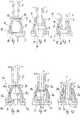
Eine Verbindungseinrichtung
Der Anschlussstutzen
Der Anschlussstutzen
Die Kappe
Der Ventilkörper
Der Ventilmantel
Zu einer Stirnseite des Bodenringes
Eine ins Innere des Ventilmantels
Der Durchtritt
Wie anhand der
Die Schlitzanordnung
Sobald nun eine Spitze eines mit dem Anschlussstutzen
Die Verbindungseinrichtung gemäß den
Auch die Kappe
Wesentlicher Unterschied des Bodenabschnittes
Dadurch, dass die Gegenschulter
Die Ventileinrichtung gemäß den
Der Ventilkörper
Bei einem Herausziehen der Spitze F stellt sich der Ventilkörper
Der Anschlussstutzen
ZITATE ENTHALTEN IN DER BESCHREIBUNG QUOTES INCLUDE IN THE DESCRIPTION
Diese Liste der vom Anmelder aufgeführten Dokumente wurde automatisiert erzeugt und ist ausschließlich zur besseren Information des Lesers aufgenommen. Die Liste ist nicht Bestandteil der deutschen Patent- bzw. Gebrauchsmusteranmeldung. Das DPMA übernimmt keinerlei Haftung für etwaige Fehler oder Auslassungen.This list of the documents listed by the applicant has been generated automatically and is included solely for the better information of the reader. The list is not part of the German patent or utility model application. The DPMA assumes no liability for any errors or omissions.
Zitierte PatentliteraturCited patent literature
- EP 1217284 B1[0002]EP 1217284 B1[0002]
- EP 1470352 B1[0003]EP 1470352 B1[0003]
- WO 2013/017698 A1[0004]WO 2013/017698 A1[0004]
Claims (14)
Translated fromGermanPriority Applications (7)
| Application Number | Priority Date | Filing Date | Title |
|---|---|---|---|
| DE102016203518.5ADE102016203518A1 (en) | 2016-03-03 | 2016-03-03 | Connecting device of a medical infusion system |
| DK17157260.5TDK3216486T3 (en) | 2016-03-03 | 2017-02-21 | CONNECTION DEVICE FOR A MEDICAL INFUSION SYSTEM |
| PL17157260TPL3216486T3 (en) | 2016-03-03 | 2017-02-21 | Connecting device of a medical infusion system |
| EP17157260.5AEP3216486B1 (en) | 2016-03-03 | 2017-02-21 | Connecting device of a medical infusion system |
| PT171572605TPT3216486T (en) | 2016-03-03 | 2017-02-21 | Connecting device of a medical infusion system |
| ES17157260TES2864955T3 (en) | 2016-03-03 | 2017-02-21 | Connecting device for a medical infusion set |
| US15/446,119US10625070B2 (en) | 2016-03-03 | 2017-03-01 | Connecting device for a medical infusion system |
Applications Claiming Priority (1)
| Application Number | Priority Date | Filing Date | Title |
|---|---|---|---|
| DE102016203518.5ADE102016203518A1 (en) | 2016-03-03 | 2016-03-03 | Connecting device of a medical infusion system |
Publications (1)
| Publication Number | Publication Date |
|---|---|
| DE102016203518A1true DE102016203518A1 (en) | 2017-09-07 |
Family
ID=58158854
Family Applications (1)
| Application Number | Title | Priority Date | Filing Date |
|---|---|---|---|
| DE102016203518.5AWithdrawnDE102016203518A1 (en) | 2016-03-03 | 2016-03-03 | Connecting device of a medical infusion system |
Country Status (7)
| Country | Link |
|---|---|
| US (1) | US10625070B2 (en) |
| EP (1) | EP3216486B1 (en) |
| DE (1) | DE102016203518A1 (en) |
| DK (1) | DK3216486T3 (en) |
| ES (1) | ES2864955T3 (en) |
| PL (1) | PL3216486T3 (en) |
| PT (1) | PT3216486T (en) |
Families Citing this family (12)
| Publication number | Priority date | Publication date | Assignee | Title |
|---|---|---|---|---|
| US20200408350A1 (en) | 2015-06-16 | 2020-12-31 | Juan Nepomuc Walterspiel | Tubing connector for decreased contamination |
| US20180296820A1 (en)* | 2017-04-13 | 2018-10-18 | Smiths Medical Asd, Inc. | Stopcock |
| JP7298595B2 (en)* | 2018-03-19 | 2023-06-27 | 株式会社ジェイ・エム・エス | female connector |
| FR3098566B1 (en)* | 2019-07-12 | 2021-06-11 | Hutchinson | FLUIDIC CONNECTION DEVICE |
| WO2022056305A1 (en)* | 2020-09-11 | 2022-03-17 | Walterspiel Juan Nepomuc | Tubing connector for decreased contamination |
| DE102021202061A1 (en) | 2021-03-03 | 2022-09-08 | B. Braun Melsungen Aktiengesellschaft | Medical product, functional part for a medical product and method for sterilizing and/or making a medical product or functional part resistant to sterilization |
| ES2937446A1 (en)* | 2021-09-27 | 2023-03-28 | Univ Del Pais Vasco / Euskal Herriko Unibertsitatea | DEVICE FOR CATHETER, A CATHETER WITH THE DEVICE, AND METHODS OF MANUFACTURING AND USE OF THE DEVICE (Machine-translation by Google Translate, not legally binding) |
| CN118574656A (en)* | 2021-12-09 | 2024-08-30 | 霍基-罗伯茨公司 | Needleless connector for disinfection in cavity |
| US20230213106A1 (en)* | 2022-01-05 | 2023-07-06 | Belgravia Wood Limited | Air valve, inflation, and deflation apparatuses and methods |
| DE102022207782A1 (en) | 2022-07-28 | 2024-02-08 | B. Braun Melsungen Aktiengesellschaft | Medical device, functional part for a medical device and method for sterilizing and/or producing sterilization resistance of a medical device or functional part |
| US12023462B2 (en)* | 2022-09-29 | 2024-07-02 | Carefusion 303, Inc. | Fluid connector system |
| US20240151339A1 (en)* | 2022-11-08 | 2024-05-09 | Carefusion 303, Inc. | Fluid connector assembly with neutral fluid displacement that limits connector damage |
Citations (5)
| Publication number | Priority date | Publication date | Assignee | Title |
|---|---|---|---|---|
| DE69317422T2 (en)* | 1992-06-04 | 1998-07-16 | Vernay Laboratories | MEDICAL COUPLING POINT |
| US6651956B2 (en)* | 2002-01-31 | 2003-11-25 | Halkey-Roberts Corporation | Slit-type swabable valve |
| US6808161B1 (en)* | 1999-09-16 | 2004-10-26 | Terumo Kabushiki Kaisha | Connector |
| US8133209B2 (en)* | 2008-05-21 | 2012-03-13 | Industrie Borla S.P.A. | Valve connector for medical lines |
| WO2013017698A1 (en) | 2011-08-04 | 2013-02-07 | B. Braun Melsungen Ag | Needle free connector with a collapsible resilient membrane fitting and corresponding method |
Family Cites Families (21)
| Publication number | Priority date | Publication date | Assignee | Title |
|---|---|---|---|---|
| US1890011A (en)* | 1930-05-05 | 1932-12-06 | Wirz Henry | Coupling device |
| US5501426A (en)* | 1992-06-04 | 1996-03-26 | Vernay Laboratories, Inc. | Medical coupling site valve body |
| US5806831A (en)* | 1993-10-13 | 1998-09-15 | Paradis; Joseph R. | Control of fluid flow with internal cannula |
| US6183448B1 (en) | 1994-06-20 | 2001-02-06 | Bruno Franz P. Mayer | Needleless injection site |
| NZ286445A (en) | 1995-05-16 | 1997-12-19 | Ivac Corp | Needleless luer connector: deformable piston occludes bore |
| US6189859B1 (en)* | 1996-08-01 | 2001-02-20 | Faulding Inc. | Indwelling catheter valve |
| US6883778B1 (en)* | 1996-11-18 | 2005-04-26 | Nypro Inc. | Apparatus for reducing fluid drawback through a medical valve |
| US5807348A (en) | 1996-11-27 | 1998-09-15 | Elcam Plastics | Needleless valve |
| US6050978A (en)* | 1997-05-09 | 2000-04-18 | Becton Dickinson And Company | Needleless valve connector |
| US7044441B2 (en)* | 2001-08-10 | 2006-05-16 | Cardinal Health 303, Inc. | Valved male luer connector having sequential valve timing |
| WO2003018104A2 (en)* | 2001-08-22 | 2003-03-06 | Nypro, Inc. | Medical valve with expandable seal member |
| US6875205B2 (en)* | 2002-02-08 | 2005-04-05 | Alaris Medical Systems, Inc. | Vial adapter having a needle-free valve for use with vial closures of different sizes |
| JP3633931B2 (en)* | 2002-08-12 | 2005-03-30 | 株式会社ジェイ・エム・エス | Needleless port and manufacturing method thereof |
| JP4064422B2 (en)* | 2003-01-09 | 2008-03-19 | フカイ工業株式会社 | Seal valve for medical device, connection port, mixed injection tube, infusion circuit connection device, and infusion circuit connection system |
| NO323929B1 (en)* | 2005-01-20 | 2007-07-23 | Vetco Gray Scandinavia As | Sealing element and coupling device provided with the same |
| WO2008130424A1 (en) | 2006-08-09 | 2008-10-30 | Halkey-Roberts Corporation | Stopcock with swabbable valve |
| US8197466B2 (en)* | 2006-11-24 | 2012-06-12 | Terumo Kabushiki Kaisha | Connector and infusion tube set |
| US9138572B2 (en)* | 2010-06-24 | 2015-09-22 | Np Medical Inc. | Medical valve with fluid volume alteration |
| PL2627385T3 (en)* | 2010-10-12 | 2016-09-30 | Medical valve assembly | |
| US9339639B2 (en)* | 2011-02-22 | 2016-05-17 | Medtronic Minimed, Inc. | Sealing assembly for a fluid reservoir of a fluid infusion device |
| FR2994392B1 (en)* | 2012-08-10 | 2014-08-08 | Cair L G L | CONNECTOR FOR MEDICAL USE |
- 2016
- 2016-03-03DEDE102016203518.5Apatent/DE102016203518A1/ennot_activeWithdrawn
- 2017
- 2017-02-21PTPT171572605Tpatent/PT3216486T/enunknown
- 2017-02-21ESES17157260Tpatent/ES2864955T3/enactiveActive
- 2017-02-21PLPL17157260Tpatent/PL3216486T3/enunknown
- 2017-02-21EPEP17157260.5Apatent/EP3216486B1/enactiveActive
- 2017-02-21DKDK17157260.5Tpatent/DK3216486T3/enactive
- 2017-03-01USUS15/446,119patent/US10625070B2/enactiveActive
Patent Citations (8)
| Publication number | Priority date | Publication date | Assignee | Title |
|---|---|---|---|---|
| DE69317422T2 (en)* | 1992-06-04 | 1998-07-16 | Vernay Laboratories | MEDICAL COUPLING POINT |
| US6808161B1 (en)* | 1999-09-16 | 2004-10-26 | Terumo Kabushiki Kaisha | Connector |
| EP1217284B1 (en) | 1999-09-16 | 2009-02-18 | Terumo Kabushiki Kaisha | Connector |
| US6651956B2 (en)* | 2002-01-31 | 2003-11-25 | Halkey-Roberts Corporation | Slit-type swabable valve |
| EP1470352B1 (en) | 2002-01-31 | 2012-09-26 | Halkey-Roberts Corporation | Slit-type swabable valve |
| US8133209B2 (en)* | 2008-05-21 | 2012-03-13 | Industrie Borla S.P.A. | Valve connector for medical lines |
| WO2013017698A1 (en) | 2011-08-04 | 2013-02-07 | B. Braun Melsungen Ag | Needle free connector with a collapsible resilient membrane fitting and corresponding method |
| US20140174578A1 (en)* | 2011-08-04 | 2014-06-26 | B. Braun Melsungen Ag | Needle free connector with a collapsible resilient membrane fitting and corresponding method |
Also Published As
| Publication number | Publication date |
|---|---|
| ES2864955T3 (en) | 2021-10-14 |
| US20170252551A1 (en) | 2017-09-07 |
| EP3216486B1 (en) | 2021-01-27 |
| US10625070B2 (en) | 2020-04-21 |
| EP3216486A1 (en) | 2017-09-13 |
| DK3216486T3 (en) | 2021-05-03 |
| PL3216486T3 (en) | 2021-09-20 |
| PT3216486T (en) | 2021-03-08 |
Similar Documents
| Publication | Publication Date | Title |
|---|---|---|
| DE102016203518A1 (en) | Connecting device of a medical infusion system | |
| EP2572750A2 (en) | Catheter device with infusion port and valves | |
| DE3532560A1 (en) | LOCKING DEVICE FOR THE MOUTHPIECE OF AN ENDOSCOPE | |
| DE2830800A1 (en) | VALVE, IN PARTICULAR MINIATURE VALVE FOR MEDICAL PURPOSES | |
| DE102011000216A1 (en) | Universal closure device | |
| DE19906870C1 (en) | Pipe connection fitting comprises components of incompatible plastic and is designed to interlock axially with rotational freedom, preventing damage to seal from rough surfaces or cuttings when tightening-up | |
| EP3954626A1 (en) | Liquid dispenser | |
| EP3292575A1 (en) | Housing comprising overpressure protection | |
| EP3601867B1 (en) | Connecting device for media lines | |
| EP2926038B1 (en) | Membrane valve | |
| EP2089084A1 (en) | Attachment for a syringe or a cartridge | |
| DE202016106073U1 (en) | Mounting system with integrated reservoir clutch for material connection | |
| DE102014213947A1 (en) | Closure device for a fluid system for medical purposes | |
| EP0879980A2 (en) | Screw coupling for hoses | |
| DE102004044288A1 (en) | Device for connecting a tubular part, in particular a cannula, to the inside of a bottle or the like | |
| AT511387A1 (en) | DENTAL PROSTHESIS | |
| EP3877092B1 (en) | Paint container for a spray gun and spray gun | |
| EP3117868A1 (en) | Connection device for wound care and wound care kit | |
| EP2927553B1 (en) | Connection, fitting and manufacturing method | |
| EP3238637A1 (en) | Compressed gas operated instrument, in particular surgical instrument | |
| DE102006027094B4 (en) | Container with interface module | |
| DE19730367B4 (en) | Elastomer sleeve for the sealing connection of two pipe ends | |
| EP3759385B1 (en) | Releasable plug connection | |
| EP2639487A1 (en) | Pipe coupling with end cap | |
| DE8701154U1 (en) | Catheter valve |
Legal Events
| Date | Code | Title | Description |
|---|---|---|---|
| R163 | Identified publications notified | ||
| R005 | Application deemed withdrawn due to failure to request examination |