DE102016124387A1 - Baubox for the additive production of a molding and arrangement - Google Patents
Baubox for the additive production of a molding and arrangementDownload PDFInfo
- Publication number
- DE102016124387A1 DE102016124387A1DE102016124387.6ADE102016124387ADE102016124387A1DE 102016124387 A1DE102016124387 A1DE 102016124387A1DE 102016124387 ADE102016124387 ADE 102016124387ADE 102016124387 A1DE102016124387 A1DE 102016124387A1
- Authority
- DE
- Germany
- Prior art keywords
- gas
- support plate
- box according
- plate
- building box
- Prior art date
- Legal status (The legal status is an assumption and is not a legal conclusion. Google has not performed a legal analysis and makes no representation as to the accuracy of the status listed.)
- Ceased
Links
- 238000004519manufacturing processMethods0.000titleclaimsabstractdescription27
- 239000000654additiveSubstances0.000titleclaimsabstractdescription7
- 230000000996additive effectEffects0.000titleclaimsabstractdescription5
- 238000000465mouldingMethods0.000titleabstractdescription8
- 239000002245particleSubstances0.000claimsabstractdescription39
- 238000007599dischargingMethods0.000claimsabstractdescription8
- 125000006850spacer groupChemical group0.000claimsabstractdescription8
- 238000009826distributionMethods0.000claimsdescription39
- 239000000843powderSubstances0.000claimsdescription26
- 239000002184metalSubstances0.000claimsdescription14
- 229910052751metalInorganic materials0.000claimsdescription14
- 238000010276constructionMethods0.000claimsdescription10
- 239000000463materialSubstances0.000claimsdescription8
- 238000003958fumigationMethods0.000claimsdescription2
- 239000007789gasSubstances0.000description121
- 238000000034methodMethods0.000description14
- 239000011230binding agentSubstances0.000description12
- 2380000101463D printingMethods0.000description8
- 239000007788liquidSubstances0.000description7
- 238000009434installationMethods0.000description6
- 239000000919ceramicSubstances0.000description3
- 238000006243chemical reactionMethods0.000description3
- 238000005058metal castingMethods0.000description3
- 239000004033plasticSubstances0.000description3
- 229920003023plasticPolymers0.000description3
- IJGRMHOSHXDMSA-UHFFFAOYSA-NAtomic nitrogenChemical compoundN#NIJGRMHOSHXDMSA-UHFFFAOYSA-N0.000description2
- 230000008878couplingEffects0.000description2
- 238000010168coupling processMethods0.000description2
- 238000005859coupling reactionMethods0.000description2
- 239000000428dustSubstances0.000description2
- 238000010894electron beam technologyMethods0.000description2
- 230000002093peripheral effectEffects0.000description2
- 239000004576sandSubstances0.000description2
- BUHVIAUBTBOHAG-FOYDDCNASA-N(2r,3r,4s,5r)-2-[6-[[2-(3,5-dimethoxyphenyl)-2-(2-methylphenyl)ethyl]amino]purin-9-yl]-5-(hydroxymethyl)oxolane-3,4-diolChemical compoundCOC1=CC(OC)=CC(C(CNC=2C=3N=CN(C=3N=CN=2)[C@H]2[C@@H]([C@H](O)[C@@H](CO)O2)O)C=2C(=CC=CC=2)C)=C1BUHVIAUBTBOHAG-FOYDDCNASA-N0.000description1
- GUBGYTABKSRVRQ-QKKXKWKRSA-NLactoseNatural productsOC[C@H]1O[C@@H](O[C@H]2[C@H](O)[C@@H](O)C(O)O[C@@H]2CO)[C@H](O)[C@@H](O)[C@H]1OGUBGYTABKSRVRQ-QKKXKWKRSA-N0.000description1
- 206010053648Vascular occlusionDiseases0.000description1
- 238000005266castingMethods0.000description1
- 229920002678cellulosePolymers0.000description1
- 235000010980celluloseNutrition0.000description1
- 238000002485combustion reactionMethods0.000description1
- 238000000605extractionMethods0.000description1
- 210000003746featherAnatomy0.000description1
- 239000002657fibrous materialSubstances0.000description1
- 238000003780insertionMethods0.000description1
- 230000037431insertionEffects0.000description1
- 239000008101lactoseSubstances0.000description1
- 230000008018meltingEffects0.000description1
- 238000010309melting processMethods0.000description1
- 150000002739metalsChemical class0.000description1
- 239000003110molding sandSubstances0.000description1
- 229910052757nitrogenInorganic materials0.000description1
- 230000035515penetrationEffects0.000description1
- 239000011148porous materialSubstances0.000description1
- 238000007711solidificationMethods0.000description1
- 230000008023solidificationEffects0.000description1
- 239000002023woodSubstances0.000description1
Images


Classifications
- B—PERFORMING OPERATIONS; TRANSPORTING
- B29—WORKING OF PLASTICS; WORKING OF SUBSTANCES IN A PLASTIC STATE IN GENERAL
- B29C—SHAPING OR JOINING OF PLASTICS; SHAPING OF MATERIAL IN A PLASTIC STATE, NOT OTHERWISE PROVIDED FOR; AFTER-TREATMENT OF THE SHAPED PRODUCTS, e.g. REPAIRING
- B29C64/00—Additive manufacturing, i.e. manufacturing of three-dimensional [3D] objects by additive deposition, additive agglomeration or additive layering, e.g. by 3D printing, stereolithography or selective laser sintering
- B29C64/20—Apparatus for additive manufacturing; Details thereof or accessories therefor
- B29C64/245—Platforms or substrates
- B—PERFORMING OPERATIONS; TRANSPORTING
- B22—CASTING; POWDER METALLURGY
- B22F—WORKING METALLIC POWDER; MANUFACTURE OF ARTICLES FROM METALLIC POWDER; MAKING METALLIC POWDER; APPARATUS OR DEVICES SPECIALLY ADAPTED FOR METALLIC POWDER
- B22F12/00—Apparatus or devices specially adapted for additive manufacturing; Auxiliary means for additive manufacturing; Combinations of additive manufacturing apparatus or devices with other processing apparatus or devices
- B22F12/30—Platforms or substrates
- B—PERFORMING OPERATIONS; TRANSPORTING
- B22—CASTING; POWDER METALLURGY
- B22F—WORKING METALLIC POWDER; MANUFACTURE OF ARTICLES FROM METALLIC POWDER; MAKING METALLIC POWDER; APPARATUS OR DEVICES SPECIALLY ADAPTED FOR METALLIC POWDER
- B22F12/00—Apparatus or devices specially adapted for additive manufacturing; Auxiliary means for additive manufacturing; Combinations of additive manufacturing apparatus or devices with other processing apparatus or devices
- B22F12/50—Means for feeding of material, e.g. heads
- B22F12/53—Nozzles
- B—PERFORMING OPERATIONS; TRANSPORTING
- B22—CASTING; POWDER METALLURGY
- B22F—WORKING METALLIC POWDER; MANUFACTURE OF ARTICLES FROM METALLIC POWDER; MAKING METALLIC POWDER; APPARATUS OR DEVICES SPECIALLY ADAPTED FOR METALLIC POWDER
- B22F12/00—Apparatus or devices specially adapted for additive manufacturing; Auxiliary means for additive manufacturing; Combinations of additive manufacturing apparatus or devices with other processing apparatus or devices
- B22F12/70—Gas flow means
- B—PERFORMING OPERATIONS; TRANSPORTING
- B29—WORKING OF PLASTICS; WORKING OF SUBSTANCES IN A PLASTIC STATE IN GENERAL
- B29C—SHAPING OR JOINING OF PLASTICS; SHAPING OF MATERIAL IN A PLASTIC STATE, NOT OTHERWISE PROVIDED FOR; AFTER-TREATMENT OF THE SHAPED PRODUCTS, e.g. REPAIRING
- B29C64/00—Additive manufacturing, i.e. manufacturing of three-dimensional [3D] objects by additive deposition, additive agglomeration or additive layering, e.g. by 3D printing, stereolithography or selective laser sintering
- B29C64/20—Apparatus for additive manufacturing; Details thereof or accessories therefor
- B29C64/255—Enclosures for the building material, e.g. powder containers
- B—PERFORMING OPERATIONS; TRANSPORTING
- B33—ADDITIVE MANUFACTURING TECHNOLOGY
- B33Y—ADDITIVE MANUFACTURING, i.e. MANUFACTURING OF THREE-DIMENSIONAL [3-D] OBJECTS BY ADDITIVE DEPOSITION, ADDITIVE AGGLOMERATION OR ADDITIVE LAYERING, e.g. BY 3-D PRINTING, STEREOLITHOGRAPHY OR SELECTIVE LASER SINTERING
- B33Y30/00—Apparatus for additive manufacturing; Details thereof or accessories therefor
- B—PERFORMING OPERATIONS; TRANSPORTING
- B22—CASTING; POWDER METALLURGY
- B22F—WORKING METALLIC POWDER; MANUFACTURE OF ARTICLES FROM METALLIC POWDER; MAKING METALLIC POWDER; APPARATUS OR DEVICES SPECIALLY ADAPTED FOR METALLIC POWDER
- B22F3/00—Manufacture of workpieces or articles from metallic powder characterised by the manner of compacting or sintering; Apparatus specially adapted therefor ; Presses and furnaces
- B22F3/10—Sintering only
- B22F3/11—Making porous workpieces or articles
- Y—GENERAL TAGGING OF NEW TECHNOLOGICAL DEVELOPMENTS; GENERAL TAGGING OF CROSS-SECTIONAL TECHNOLOGIES SPANNING OVER SEVERAL SECTIONS OF THE IPC; TECHNICAL SUBJECTS COVERED BY FORMER USPC CROSS-REFERENCE ART COLLECTIONS [XRACs] AND DIGESTS
- Y02—TECHNOLOGIES OR APPLICATIONS FOR MITIGATION OR ADAPTATION AGAINST CLIMATE CHANGE
- Y02P—CLIMATE CHANGE MITIGATION TECHNOLOGIES IN THE PRODUCTION OR PROCESSING OF GOODS
- Y02P10/00—Technologies related to metal processing
- Y02P10/25—Process efficiency
Landscapes
- Engineering & Computer Science (AREA)
- Chemical & Material Sciences (AREA)
- Materials Engineering (AREA)
- Manufacturing & Machinery (AREA)
- Mechanical Engineering (AREA)
- Physics & Mathematics (AREA)
- Optics & Photonics (AREA)
- Powder Metallurgy (AREA)
Abstract
Translated fromGermanDescription
Translated fromGermanDie Erfindung betrifft eine Baubox zur additiven Herstellung eines Formteils und eine Anordnung, welche die Baubox umfasst.The invention relates to a Baubox for additive production of a molded part and an arrangement comprising the Baubox.
Nach dem Stand der Technik ist beispielsweise in der
Das vorgenannte Verfahren wird auch als 3D-Druckverfahren bezeichnet. Mit diesem Verfahren lassen sich Formteile aus Kunststoff, Metall, Keramik und insbesondere auch aus einem Formsand herstellen. Die Pulverpartikel können mittels eines Lasers, Elektronenstrahls oder auch durch das Auftragen einer aushärtbaren Flüssigkeit selektiv miteinander verbunden werden.The aforementioned method is also called a 3D printing method. With this method can be molded parts made of plastic, metal, ceramic and in particular also made of a molding sand. The powder particles can be selectively connected to each other by means of a laser, electron beam or by the application of a curable liquid.
Das 3D-Druckverfahren eignet sich insbesondere zur Herstellung von Formen und/oder Formkernen, welche zur Herstellung von Gussteilen aus Metall verwendet werden. Es wird verwiesen auf die
Obgleich das 3D-Druckverfahren nach dem Stand der Technik bereits Formteile in einer guten Qualität liefert, ist es für die Serienfertigung bisher insbesondere aus wirtschaftlichen Gründen noch ungeeignet. Insbesondere zur Herstellung von Gussteilen wäre eine Serienfertigung von Formen und/oder Formkernen nach dem 3D-Druckverfahren vorteilhaft.Although the 3D printing method according to the prior art already delivers molded parts in a good quality, it has hitherto been unsuitable for series production, in particular for economic reasons. In particular for the production of cast parts, a series production of molds and / or mold cores according to the 3D printing method would be advantageous.
Aus der
Die
Aufgabe der Erfindung ist, die Nachteile nach dem Stand der Technik zu beseitigen. Es sollen insbesondere eine Baubox und eine Anordnung angegeben werden, welche eine Serienproduktion von Formteilen in 3D-Druckverfahren ermöglichen. Mit der Erfindung soll insbesondere eine Serienproduktion von Formen und/oder Formkernen für den Metallguss angegeben werden.The object of the invention is to eliminate the disadvantages of the prior art. In particular, a building box and an arrangement are to be specified, which enable a series production of molded parts in 3D printing processes. With the invention, in particular, a series production of molds and / or mandrels for metal casting is to be specified.
Diese Aufgabe wird durch die Merkmale der Patentansprüche 1 und 16 gelöst. Zweckmäßige Ausgestaltungen der Erfindung ergeben sich aus den Merkmalen der Patentansprüche 2 bis 15 und 17 bis 24.This object is solved by the features of
Nach Maßgabe der Erfindung wird eine Baubox zur additiven Herstellung eines Formteils vorgeschlagen, umfassend eine von Wänden umgebene Bauplattform, welche relativ zu den Wänden absenk- und anhebbar ist,
wobei die Bauplattform eine Lochplatte zum Abstützen des Formteils umfasst, welche derart ausgebildet ist, dass sie einen Durchtritt von zur Herstellung des Formteils verwendeten losen Partikeln ermöglicht,
wobei die Lochplatte mittels Abstandshaltern auf einer Stützplatte abgestützt ist, und
wobei die Stützplatte zumindest einen mit einem Verschlussmittel verschließbaren ersten Durchbruch zum wahlweisen Abführen der losen Partikel aufweist.According to the invention, a building box is proposed for the additive production of a molded part, comprising a building platform surrounded by walls, which can be lowered and raised relative to the walls,
wherein the building platform comprises a perforated plate for supporting the molded part, which is designed such that it allows a passage of loose particles used for the production of the molded part,
wherein the perforated plate is supported by means of spacers on a support plate, and
wherein the support plate has at least one closable with a closure means first opening for selectively discharging the loose particles.
Die „Lochplatte“ im Sinne der vorliegenden Erfindung weist Durchbrüche auf, welche einen Durchtritt von zur Herstellung des Formteils verwendeten losen Partikeln ermöglichen. Die Durchbrüche haben üblicherweise einen mittleren Durchmesser im Bereich von 1 bis 50 mm. Ein Durchmesser der Durchbrüche ist selbstverständlich so gewählt, dass das herzustellende Formteil auf der Lochplatte sicher abgestützt wird.The "perforated plate" in the sense of the present invention has openings, which allow a passage of loose particles used for the production of the molding. The apertures usually have a mean diameter in the range of 1 to 50 mm. A diameter of the openings is of course chosen so that the molded part to be produced is securely supported on the perforated plate.
Die Lochplatte ist mittels Abstandshaltern auf einer Stützplatte abgestützt. D. h. zwischen der Lochplatte und der Stützplatte ist bedingt durch die Abstandshalter ein Zwischenraum gebildet. Bei der Herstellung des Formteils ist der Zwischenraum zwischen der Lochplatte und der Stützplatte weitgehend mit losen Partikeln gefüllt.The perforated plate is supported by means of spacers on a support plate. Ie. between the perforated plate and the support plate is formed by the spacers a gap. In the production of the molded part, the gap between the perforated plate and the support plate is largely filled with loose particles.
Die Stützplatte weist zumindest einen mit einem Verschlussmittel verschließbaren ersten Durchbruch zum wahlweisen Abführen der losen Partikel auf. D. h. wenn das Verschlussmittel geöffnet wird, können die losen Partikel aus dem Zwischenraum abgeführt werden. Infolgedessen rieseln aus einem das Formteil aufnehmenden Bauraum weitere lose Partikel in den Zwischenraum nach und können ebenfalls durch den ersten Durchbruch abgeführt werden. Infolgedessen kann das Formteil durch Öffnen des Verschlussmittels von den umgebenden losen Partikeln befreit werden, derart, dass es beispielsweise mit einem Roboter gegriffen und von der Bauplattform abgehoben werden kann.The support plate has at least one closable with a closure means first opening for selectively removing the loose particles. Ie. When the closure means is opened, the loose particles can be removed from the gap. As a result, more loose particles trickle from a space receiving the molding into the space and can also be removed by the first breakthrough. As a result, the molded article may be opened by opening the closure means from the surrounding loose particles be freed, such that it can be grasped for example with a robot and lifted off the build platform.
Die vorgeschlagene Baubox ist vorteilhafterweise so ausgebildet, dass sie aus einem 3D-Drucker entnommen werden kann. D. h. die Baubox kann in dieser Ausführung von einem Antrieb zum Verstellen der Höhe der Bauplattform getrennt bzw. abgekuppelt werden. Desgleichen kann die Baubox von einer Einrichtung zum selektiven Verfestigen der losen Partikel gemäß einem vorgegebenen Programm getrennt werden. In vom 3D-Drucker entfernten Zustand ist es möglich, die losen Partikel schnell und einfach vom Formteil zumindest teilweise zu trennen, so dass das Formteil von der Bauplattform abgehoben und weiteren Fertigungsschritten zugeführt werden kann. Das ermöglicht eine Serienproduktion beispielsweise von Formen und/oder Formkernen für den Metallguss.The proposed Baubox is advantageously designed so that it can be removed from a 3D printer. Ie. The Baubox can be separated or disconnected in this embodiment of a drive for adjusting the height of the build platform. Likewise, the construction box may be separated from a means for selectively solidifying the loose particles according to a predetermined program. In the state removed from the 3D printer, it is possible to separate the loose particles quickly and easily from the molded part, at least in part, so that the molded part can be lifted off the build platform and fed to further production steps. This allows a series production of, for example, molds and / or mold cores for metal casting.
Als „Partikel“ können im Sinne der Erfindung alle das 3D-Verfahren bekannten Materialien verwendet werden, insbesondere Sande, Keramik, Metall, Kunststoff, Holz, Faserwerkstoffe, Zellulosen und/oder Laktosepulver. Die Partikel liegen vorzugsweise als trocken, frei fließendes Pulver vor.For the purposes of the invention, "particles" can be all materials known for the 3D process, in particular sands, ceramics, metals, plastics, wood, fiber materials, celluloses and / or lactose powders. The particles are preferably in the form of a dry, free-flowing powder.
Nach einer vorteilhaften Ausgestaltung ist das Verschlussmittel gemeinsam mit der Stützplatte höhenverstellbar und relativ zur Stützplatte bewegbar. Das Verschlussmittel bildet vorzugsweise gemeinsam mit der Baubox ein austauschbares Modul. Es ist vorteilhafterweise so ausgebildet, dass es nach der Entnahme der Baubox aus einem 3D-Drucker in einer gesonderten Station wahlweise geöffnet und/oder geschlossen werden kann.According to an advantageous embodiment, the closure means is vertically adjustable together with the support plate and movable relative to the support plate. The closure means preferably forms an exchangeable module together with the building box. It is advantageously designed so that it can be selectively opened and / or closed after removal of the Baubox from a 3D printer in a separate station.
Nach einer besonders vorteilhaften Ausgestaltung ist eine Gaszuführeinrichtung zum Zuführen von Gas in einen von der Lochplatte und den Wänden begrenzten Bauraum vorgesehen. Bei dem Gas handelt es sich zweckmäßigerweise um heiße Luft, heißen Stickstoff oder auch heiße Abgase, welche beispielsweise aus einem Schmelz- oder Verbrennungsprozess ausgekoppelt werden können. Das, vorzugsweise heiße, Gas dient dazu, ein zum Binden beispielsweise von aus Sand hergestellten Partikeln verwendetes flüssiges Bindemitteln zu trocknen bzw. auszuhärten. - Bei dem Gas kann es sich auch um ein reaktives Gas handeln, welches chemisch mit dem Bindemittel reagiert oder eine chemische Reaktion des Bindemittels bewirkt. Durch die chemische Reaktion verfestigt sich das Bindemittel. Bei dem reaktiven Gas kann es sich beispielsweise um CO2 handeln.According to a particularly advantageous embodiment, a gas supply device is provided for supplying gas into a space bounded by the perforated plate and the walls. The gas is expediently hot air, hot nitrogen or hot exhaust gases, which can be coupled out, for example, from a melting or combustion process. The, preferably hot, gas serves to dry or cure a liquid binder used for bonding, for example, particles made of sand. - The gas may also be a reactive gas which reacts chemically with the binder or causes a chemical reaction of the binder. Due to the chemical reaction, the binder solidifies. The reactive gas may be, for example, CO2 .
Die Stützplatte ist zweckmäßigerweise zumindest abschnittsweise aus einem gasdurchlässigen Sinterwerkstoff, vorzugsweise einem Sintermetall, hergestellt. Die Stützplatte kann insbesondere Durchbrüche aufweisen, welche mit aus einem Sintermetall hergestellten Einsätzen verschlossen sind.The support plate is expediently at least partially made of a gas-permeable sintered material, preferably a sintered metal. The support plate may in particular have openings which are closed with inserts made of a sintered metal.
Die Gaszuführeinrichtung kann eine der Stützplatte zugeordnete Gasverteilungseinrichtung umfassen. Die Gasverteilungseinrichtung kann eine Vielzahl von in der Stützplatte vorgesehenen zweiten Durchbrüchen aufweisen, an denen jeweils ein sich von der Stützplatte in Richtung der Lochplatte erstreckender Gasstutzen angeschlossen ist.The gas supply device may comprise a gas distribution device associated with the support plate. The gas distribution device can have a multiplicity of second openings provided in the support plate, to each of which a gas nozzle extending from the support plate in the direction of the perforated plate is connected.
Nach einer Ausgestaltung kann der Gasstutzen im Bereich eines von der Stützplatte entfernten freien Endes mit einem Verschluss aus einem gasdurchlässigen Sinterwerkstoff, vorzugsweise Sintermetall, versehen sein. - Gasdurchlässige Sinterwerkstoffe können auch aus anderen Materialien, beispielsweise Keramik hergestellt sein. Gasdurchlässige Sinterwerkstoffe weisen eine offene bzw. durchgängige Porosität auf, welche einen Durchtritt von Gas ermöglicht und gleichzeitig ein Eindringen von losen Partikeln verhindert. Ein mittlerer Porendurchmesser derartiger Sinterwerkstoffe kann in geeigneter Weise so gewählt werden, dass er stets kleiner als beispielsweise ein mittlerer Korngrößendurchmesser der losen Partikel ist.According to one embodiment, the gas nozzle in the region of a free end remote from the support plate with a closure of a gas-permeable sintered material, preferably sintered metal, be provided. - Gas-permeable sintered materials may also be made of other materials, such as ceramic. Gas-permeable sintered materials have an open or continuous porosity, which allows a passage of gas and at the same time prevents the penetration of loose particles. An average pore diameter of such sintered materials may be suitably selected to be always smaller than, for example, a mean grain size diameter of the loose particles.
Der Gasstutzen kann nach einer alternativen Ausgestaltung auch als Düsenstock ausgebildet sein, welcher vorteilhafterweise eine Vielzahl von Düsen aufweist, welche sich im Bereich eines von der Stützplatte entfernten freien Endes des Düsenstocks zum Zwischenraum zwischen der Loch- und der Stützplatte hin öffnen. Die Düsenstöcke können zylindrisch ausgebildet sein. Die Düsen können sich am freien Ende radial erstrecken, d. h. am Umfang des zylindrischen Düsenstocks sich öffnen.The gas nozzle may be formed according to an alternative embodiment as a nozzle, which advantageously has a plurality of nozzles which open in the region of a remote from the support plate free end of the nozzle block to the space between the perforated and the support plate. The nozzle sticks can be cylindrical. The nozzles may extend radially at the free end, i. H. Open at the circumference of the cylindrical nozzle block.
Die Stützplatte ist zweckmäßigerweise auf einer Gasverteilungsplatte abgestützt, welche zu den zweiten Durchbrüchen hin sich öffnende Gasverteilungskanäle aufweist. Die Gasverteilungsplatte weist zumindest einen dritten Durchbruch (i) zum Zuführen von Gas zu oder (ii) zum Abführen von Gas von den Gasverteilungskanälen auf. Die Gasverteilungskanäle dienen entweder dem gleichmäßigen Verteilen und dem Zuführen von Gas zu den zweiten Durchbrüchen oder dem Sammeln und Abführen von Gas von den zweiten Durchbrüchen.The support plate is expediently supported on a gas distribution plate which has gas distribution channels opening towards the second openings. The gas distribution plate has at least one third opening (i) for supplying gas to or (ii) for discharging gas from the gas distribution channels. The gas distribution channels serve to either evenly distribute and supply gas to the second apertures or to collect and remove gas from the second apertures.
Die Gasverteilungseinrichtung kann auch eine poröse Platte umfassen, welche die Düsenstöcke und/oder die Stützplatte ersetzt. Eine solche poröse Platte kann beispielsweise aus einem Sintermetall hergestellt sein. Es ist auch denkbar, anstelle der Düsenstöcke in der Stützplatte Abschnitte vorzusehen, welche porös bzw. gasdurchlässig ausgebildet sind. Solche Abschnitte können ebenfalls aus Sintermetall oder dgl. gebildet sein.The gas distribution device may also comprise a porous plate which replaces the nozzle holders and / or the support plate. Such a porous plate may be made of a sintered metal, for example. It is also conceivable to provide instead of the nozzle sticks in the support plate sections which are formed porous or gas-permeable. Such portions may also be formed of sintered metal or the like.
Die Gasverteilungsplatte ist vorteilhafterweise auf einer Trägerplatte abgestützt. Die Trägerplatte bildet einen Boden der Bauplattform. - Bei der Stützplatte, der Gasverteilungsplatte und/oder der Trägerplatte kann es sich um separate Bauteile handeln, welche aufeinander abgestützt oder miteinander verbunden sind. Es kann aber auch sein, dass zwei der vorgenannten Platten oder sämtliche Platten in einem Stück, beispielsweise im 3D-Druckverfahren, hergestellt sind. The gas distribution plate is advantageously supported on a support plate. The carrier plate forms a bottom of the build platform. - The support plate, the gas distribution plate and / or the support plate may be separate components which are supported on each other or interconnected. But it may also be that two of the aforementioned plates or all plates are made in one piece, for example in the 3D printing process.
Das Verschlussmittel umfasst zumindest einen Ventilstempel. Der Ventilstempel erstreckt sich zweckmäßigerweise durch die Trägerplatte und die Gasverteilungsplatte. Der Ventilstempel ist vorteilhafterweise stabförmig ausgebildet und weist ein konisches Verschlussende auf, welches in einer Schließstellung formschlüssig an einem vorzugsweise korrespondierend dazu ausgebildeten, konisch sich zur Trägerplatte hin öffnenden ersten Durchbruch anliegt. Vorteilhafterweise ist der Ventilstempel an der Stütz-, Gasverteilungs- oder Trägerplatte unter einer Vorspannung derart gehalten, dass ein Verschlussende des Ventilstempels in eine den ersten Durchbruch verschließende Stellung gezwungen wird. Zur Erzeugung der Vorspannung wird zweckmäßigerweise eine Feder verwendet.The closure means comprises at least one valve stamper. The valve stem expediently extends through the carrier plate and the gas distribution plate. The valve stem is advantageously designed rod-shaped and has a conical closure end, which in a closed position positively against a preferably corresponding thereto formed, conically opening to the support plate opening first breakthrough. Advantageously, the valve stem is held on the support, gas distribution or support plate under a bias such that a closure end of the valve stem is forced into a position closing the first breakthrough. To generate the bias voltage, a spring is suitably used.
Ein dem Verschlussende des Ventilstempels gegenüberliegendes Anschlussende ist zweckmäßigerweise als Greifstück ausgebildet. - In der vorgeschlagenen Ausgestaltung des Verschlussmittels bildet der Ventilstempel eine an der Bauplattform gehaltene autonome Einheit, welche durch Koppeln des Anschlussendes mit einer Bewegungseinrichtung betätigt werden kann.A connection end opposite the closure end of the valve stem is expediently designed as a gripping piece. - In the proposed embodiment of the closure means of the valve stamper forms an autonomous unit held on the building platform, which can be actuated by coupling the connection end with a moving device.
Die vorgeschlagene Baubox ist vorteilhafterweise als Modul ausgebildet, welches außerhalb eines 3D-Druckers mit Gas gespült und aus dem nachfolgend die im Bauraum verbliebenen losen Partikel durch Öffnen des Verschlussmittels abgeführt werden können. Damit ist es möglich, ein insbesondere mittels eines flüssigen Bindemittels befestigtes Formteil beispielsweise mittels eines Roboters von der Bauplattform abzuheben und aus der Baubox zu entnehmen. Das ermöglicht eine Serienfertigung, beispielsweise von Formen und/oder Formkernen für den Metallguss. Die vorgeschlagene Baubox eignet sich selbstverständlich auch für die Serienfertigung anderer nach dem 3D-Druckverfahren hergestellter Teile, beispielsweise Kunststoffteile, Metallteile und dgl. Dabei kann die Verfestigung der losen Partikel mittels Laser, Elektrodenstrahl oder anderer bekannter Techniken erfolgen.The proposed Baubox is advantageously designed as a module which rinsed outside of a 3D printer with gas and from which subsequently the loose particles remaining in the space can be removed by opening the closure means. This makes it possible to lift a particular fixed by means of a liquid binder molded part, for example by means of a robot from the building platform and to remove from the Baubox. This enables mass production, for example of molds and / or mold cores for metal casting. The proposed Baubox is of course also suitable for the mass production of other manufactured by the 3D printing process parts, such as plastic parts, metal parts and the like. In this case, the solidification of the loose particles by means of laser, electron beam or other known techniques.
Nach einem weiteren Aspekt ist die vorliegende Erfindung gerichtet auf eine Anordnung, umfassend eine erfindungsgemäße Baubox und eine Pulverentladestation mit einer Vorrichtung zum wahlweisen Öffnen und Schließen des Verschlussmittels. - Die Pulverentladestation befindet sich außerhalb eines 3D-Druckers. Die erfindungsgemäße Baubox wird als Modul gemeinsam mit dem darin hergestellten Formteil aus dem 3D-Drucker entnommen und zur Pulverentladestation verfahren. Dazu können beispielsweise Schienen oder dgl. vorgesehen sein. In der Pulverentladestation können dann durch Betätigen des Verschlussmittels die losen Partikel aus dem Bauraum zumindest zum Teil abgelassen werden. Damit ist es möglich, ein im Bauraum hergestelltes Formteil freizulegen, so dass es gegriffen und aus dem Bauraum abtransportiert werden kann.In another aspect, the present invention is directed to an assembly comprising a construction box according to the invention and a powder discharge station having means for selectively opening and closing the closure means. - The powder discharge station is located outside of a 3D printer. The Baubox invention is taken as a module together with the molded part produced therein from the 3D printer and moved to Pulverentladestation. For this purpose, for example, rails or the like. Be provided. In the powder discharge station, the loose particles can then be at least partially drained from the installation space by actuating the closure means. This makes it possible to expose a molded part produced in the space so that it can be grasped and removed from the installation space.
Vorteilhafterweise ist die Pulverentladestation mit einer Ventilbetätigungsrichtung versehen, welche einen zum Greifstück korrespondierenden Greifer aufweist, wobei der Greifer mittels einer Verstelleinrichtung zum wahlweisen Öffnen und Schließen des Ventils höhenverstellbar ist. Bei dem Greifer kann es sich um einen mechanischen Greifer, beispielsweise einen Haken oder ein anders artig ausgestaltetes mechanisches Greifmittel handeln. Der Greifer kann auch ein elektrisch, hydraulisch oder pneumatisch betätigbares Greifelement zum Greifen des Greifstücks aufweisen. Mittels des Greifers kann das Ventil entgegen der in Verschlussrichtung wirkenden Vorspannung in eine Richtung weg von der Trägerplatte bewegt und damit der erste Durchbruch geöffnet werden.Advantageously, the powder discharge station is provided with a valve actuation direction, which has a gripper corresponding gripper, wherein the gripper by means of an adjusting device for selectively opening and closing the valve is height adjustable. The gripper can be a mechanical gripper, for example a hook or a differently designed mechanical gripping means. The gripper may also have an electrically, hydraulically or pneumatically operable gripping element for gripping the gripping piece. By means of the gripper, the valve can be moved counter to the bias acting in the closing direction in a direction away from the carrier plate and thus the first opening can be opened.
Nach einer weiteren vorteilhaften Ausgestaltung weist die Pulverentladestation eine Auffangeinrichtung zum Auffangen von durch den ersten Durchbruch abgeführten Pulver auf. Es kann sich dabei um einen Behälter handeln, welcher unterhalb der Ventilbetätigungsvorrichtung vorgesehen ist. Der Behälter ist vorteilhafterweise so ausgestaltet, dass er aus der Pulverentladestation entfernt und gegen einen leeren Behälter ausgetauscht werden kann. - Es kann auch eine Vorrichtung zum kontinuierlichen Abtransport des abgeführten Pulvers vorgesehen sein. Eine solche Vorrichtung kann anstelle des Behälters einen Sammeltrichter umfassen. Sie kann ferner einen Schneckenförderer, einen Bandförderer und dgl. umfassen.According to a further advantageous embodiment, the powder discharge station has a collecting device for collecting powder discharged through the first opening. It may be a container which is provided below the valve actuating device. The container is advantageously designed so that it can be removed from the powder discharge station and replaced with an empty container. - It can also be provided a device for the continuous removal of the discharged powder. Such a device may comprise a collecting hopper instead of the container. It may further comprise a screw conveyor, a belt conveyor and the like.
Der Pulverentladestation ist zweckmäßigerweise ein Roboter oder dgl. zum Greifen und Entladen eines auf der Bauplattform hergestellten Formteils zugeordnet. Das ermöglicht eine weitere Automatisierung bei der Herstellung von Formteilen im 3D-Druckverfahren.The powder discharge station is expediently associated with a robot or the like for gripping and unloading a molded part produced on the building platform. This enables further automation in the production of molded parts in the 3D printing process.
Nach einer weiteren Ausgestaltung weist die Anordnung eine Begasungsstation mit einer Begasungseinrichtung auf, wobei die Begasungseinrichtung eine Druckerzeugungseinrichtung zum Erzeugen eines unter einem Überdruck stehenden Gases aufweist. Bei der Druckerzeugungseinrichtung kann es sich um ein Gebläse, einen Kompressor, einen Druckgasvorrat, beispielsweise eine Gasflasche, oder dgl. handeln.According to a further embodiment, the arrangement has a gassing station with a gassing device, wherein the gassing device has a pressure generating device for generating a gas under an overpressure. In the pressure generating device it may be a fan, a compressor, a pressurized gas supply, such as a gas cylinder, or the like. Act.
Vorteilhafterweise ist stromabwärts der Druckerzeugungseinrichtung eine Gaszuführleitung zum Zuführen von Gas zu einem korrespondierend zum dritten Durchbruch ausgebildeten Anschlussstück zum Verbinden der Gaszuführleitung mit der Gasverteilungsplatte vorgesehen.Advantageously, downstream of the pressure generating device, a gas supply line is provided for supplying gas to a connection piece corresponding to the third opening for connecting the gas supply line to the gas distribution plate.
Die Begasungseinrichtung ist zweckmäßigerweise zwischen den 3D-Drucker und die Pulverentladestation geschaltet. Die vorgeschlagene Begasungseinrichtung ist insbesondere dann erforderlich, wenn die losen Partikel mittels eines flüssigen Bindemittels gebunden werden, welches durch Beaufschlagung von Gas getrocknet und/oder gehärtet werden kann. In der Begasungseinrichtung kann z. B. mittels des Anschlussstücks eine Verbindung zum dritten Durchbruch hergestellt werden. Anschließend kann durch die Gaszuführleitung beispielsweise heiße Luft durch die Gaszuführleitung zur Gasverteilungsplatte und von da zu den Düsenstöcken transportiert werden. Von den Düsenstöcken gelangt das heiße Gas durch die darüber befindliche Schüttung aus losen und mittels eines flüssigen Bindemittels teilweise verfestigten Partikeln. Durch die Wirkung des heißen Gases trocknet und verfestigt sich das Bindemittel, so dass das Formteil formstabil wird und aus dem Bauraum entfernt werden kann. - Im Falle der Verwendung eines reaktiven Gases härtet das Bindemittel infolge einer chemischen Reaktion aus.The gassing device is expediently connected between the 3D printer and the powder discharge station. The proposed gassing device is particularly necessary when the loose particles are bound by means of a liquid binder, which can be dried and / or cured by the application of gas. In the gassing z. B. by means of the connection piece to connect to the third breakthrough. Subsequently, for example, hot air can be transported through the gas supply line to the gas distribution plate and from there to the nozzle blocks through the gas supply line. From the nozzle sticks, the hot gas passes through the overlying bed of loose and partially solidified by means of a liquid binder particles. By the action of the hot gas, the binder dries and solidifies, so that the molded part is dimensionally stable and can be removed from the installation space. - In the case of using a reactive gas, the binder hardens as a result of a chemical reaction.
Nach einer weiteren Ausgestaltung weist die Begasungseinrichtung eine dem Anschlussstück gegenüberliegende, relativ dazu höhenverstellbare Gasabzugs- oder Gaszuführhaube mit einem Gasabzugsstutzen auf. Die Gasabzugs- oder Gaszuführhaube ist zweckmäßigerweise so ausgestaltet, dass deren Außenumfang etwa zum Innenumfang der die Bauplattform umgebenden Wände korrespondiert. D. h. die Gasabzugs- oder Gaszuführhaube kann beispielsweise randlich auf die im Bauraum befindliche Schüttung aus losen und teilweise verfestigten Partikeln gesetzt werden. Es ist aber auch möglich, dass die Gasabzugs- oder Gaszuführhaube so ausgestaltet ist, dass sie auf die Oberkante der Wände aufgesetzt werden kann.In accordance with a further embodiment, the gassing device has a gas outlet or gas supply hood, which is opposite the connection piece and relatively height-adjustable, with a gas outlet nozzle. The gas exhaust or gas supply hood is expediently designed such that its outer circumference corresponds approximately to the inner circumference of the walls surrounding the building platform. Ie. The gas extraction or gas supply hood can be placed, for example, marginally on the bed located in the space from loose and partially solidified particles. But it is also possible that the gas vent or gas supply hood is designed so that it can be placed on the top of the walls.
Bei der Gasabzugshaube kann der Gasabzugsstutzen mit einer Filtereinrichtung versehen sein, in der eine im abgeführten Gasstrom enthaltene Staubfraktion und/oder in Pulverform vorliegende Additive abgetrennt werden kann. Insbesondere pulverförmige Additive können einer erneuten Verwendung zugeführt werden. Dem Gasabzugsstutzen kann zum Abführen des Gases ein Sauggebläse stromabwärts nachgeordnet sein.In the gas exhaust hood, the gas outlet nozzle may be provided with a filter device in which a dust fraction present in the discharged gas stream and / or additives present in powder form can be separated off. In particular, powdery additives can be supplied for reuse. The gas outlet nozzle may be downstream downstream of a suction fan for discharging the gas.
Durch die Gaszuführhaube kann Gas von oben her dem Bauraum zugeführt und durch die darin aufgenommene Schüttung aus losen und teilweise verfestigten Partikeln gedrückt werden. Stromabwärts der Stützplatte kann in diesem Fall zusätzlich ein Sauggebläse vorgesehen sein, mit dem das durch die Gaszuführhaube zugeführte Gas abgeführt wird.Gas can be supplied from above through the gas supply hood to the installation space and pressed by the bed of loose and partially solidified particles received therein. Downstream of the support plate can be provided in this case, in addition, a suction fan, with which the gas supplied through the gas supply hood gas is discharged.
Zur Automatisierung des mit der erfindungsgemäßen Anordnung durchführbaren Verfahrens ist zweckmäßigerweise eine Steuerung zum Steuern der Begasung, der Pulverentladung und/oder des Greifens des Formteils vorgesehen.To automate the process which can be carried out with the arrangement according to the invention, it is expedient to provide a controller for controlling the fumigation, the powder discharge and / or the gripping of the molded part.
Nachfolgend wird anhand der Zeichnungen ein Ausführungsbeispiel der Erfindung näher erläutert. Es zeigen:
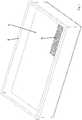
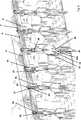
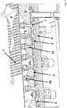
1 eine perspektivische Ansicht auf eine Baubox,2 eine erste perspektivische Schnittansicht durch dieBaubox gemäß 1 ,3 eine zweite perspektivische Schnittansicht durch dieBaubox gemäß 1 ,4 eine perspektivische Schnittansicht durch dieDüsenstöcke gemäß 3 ,5 eine perspektivische Schnittansicht durch eine Begasungsstation mit der darin aufgenommenen Baubox,6 eine schematische Teilschnittansicht durch eine Pulverentladestation mit der darin aufgenommenen Baubox und7 eine perspektivische Schnittansicht durch Gasstutzen mit einem Verschluss aus Sintermetall.
1 a perspective view of a construction box,2 a first perspective sectional view through the Baubox according to1 .3 a second perspective sectional view through the Baubox according to1 .4 a sectional perspective view through the nozzle sticks according to3 .5 a perspective sectional view through a gassing station with the Baubox received therein,6 a schematic partial sectional view through a Pulverentladestation with the Baubox received therein and7 a sectional perspective view through gas nozzle with a closure made of sintered metal.
Die Lochplatte
Die Stützplatte
Die Gasverteilungsplatte
In der Stützplatte
Die Begasungsstation umfasst ferner eine mit dem Bezugszeichen
Die Pulverentladestation weist zu den Greifstücken
Durch Bewegen einer mit dem Kolben
Eine den Pneumatikzylinder
Mit der vorgeschlagenen Anordnung kann folgendes Verfahren durchgeführt werden: With the proposed arrangement, the following procedure can be carried out:
Zunächst wird die Baubox in einen geeigneten 3D-Drucker eingesetzt. Dort kann in herkömmlicher Weise ein Formteil aus einem Gusssand hergestellt werden, wobei lose Partikel
Sobald das Formteil ausreichend verfestigt ist, wird die Baubox aus der Begasungsstation entnommen und der Pulverentladestation zugeführt. Dort werden die Greifstücke
Die vorgeschlagene Baubox sowie die Anordnung ermöglichen die serienmäßige Herstellung von Formteilen. Sofern die Partikel nicht mit einem flüssigen Bindemittel gebunden werden, kann die Begasungsstation auch weggelassen werden.The proposed Baubox and the arrangement allow the serial production of molded parts. Unless the particles are bound with a liquid binder, the gassing station may also be omitted.
BezugszeichenlisteLIST OF REFERENCE NUMBERS
- 11
- Bauplattformbuilding platform
- 22
- Wandwall
- 33
- Lochplatteperforated plate
- 44
- Stützplattesupport plate
- 55
- Abstandshalterspacer
- 66
- GasverteilungsplatteGas distribution plate
- 77
- GasverteilungskanalGas distribution channel
- 88th
- zweiter Durchbruchsecond breakthrough
- 99
- Trägerplattesupport plate
- 1010
- dritter Durchbruchthird breakthrough
- 1111
- Gasstutzengas nozzles
- 1212
- erster Durchbruchfirst breakthrough
- 1313
- Verschlussmittelclosure means
- 1414
- Düsejet
- 1515
- Begasungseinrichtunggassing
- 1616
- Gaszuführleitunggas supply
- 1717
- GasanschlussstutzenGas couplings
- 1818
- GasverteilungsleitungGas distribution line
- 1919
- GasabzugshaubeGas hood
- 2020
- GasabzugsstutzenGas vent nozzle
- 2121
- weitere Stützplattefurther support plate
- 2222
- Ventilstempelvalve stem
- 2323
- Verschlussendebreech end
- 2424
- Verschlussstückclosing piece
- 2525
- Anschlussendeterminal end
- 2626
- Greifstückcross piece
- 2727
- Halteeinrichtungholder
- 2828
- Federfeather
- 2929
- Greifergrab
- 3030
- Kolbenpiston
- 30a30a
- Pneumatikzylinderpneumatic cylinder
- 3131
- Kolbenstangepiston rod
- 32 32
- pneumatische Einrichtungenpneumatic equipment
- 3333
- Abdeckungcover
- 3434
- Verschlussshutter
- PP
- lose Partikelloose particles
- ZZ
- Zwischenraumgap
ZITATE ENTHALTEN IN DER BESCHREIBUNG QUOTES INCLUDE IN THE DESCRIPTION
Diese Liste der vom Anmelder aufgeführten Dokumente wurde automatisiert erzeugt und ist ausschließlich zur besseren Information des Lesers aufgenommen. Die Liste ist nicht Bestandteil der deutschen Patent- bzw. Gebrauchsmusteranmeldung. Das DPMA übernimmt keinerlei Haftung für etwaige Fehler oder Auslassungen.This list of the documents listed by the applicant has been generated automatically and is included solely for the better information of the reader. The list is not part of the German patent or utility model application. The DPMA assumes no liability for any errors or omissions.
Zitierte PatentliteraturCited patent literature
- EP 0431924 B1 [0002]EP 0431924 B1 [0002]
- WO 2016/019937 A1 [0004]WO 2016/019937 A1 [0004]
- DE 112008000475 T5 [0006]DE 112008000475 T5 [0006]
- DE 102009056696 B4 [0007]DE 102009056696 B4 [0007]
Claims (24)
Translated fromGermanApplications Claiming Priority (2)
| Application Number | Priority Date | Filing Date | Title |
|---|---|---|---|
| DE102016222387.9 | 2016-11-15 | ||
| DE102016222387 | 2016-11-15 |
Publications (1)
| Publication Number | Publication Date |
|---|---|
| DE102016124387A1true DE102016124387A1 (en) | 2018-05-17 |
Family
ID=62026247
Family Applications (1)
| Application Number | Title | Priority Date | Filing Date |
|---|---|---|---|
| DE102016124387.6ACeasedDE102016124387A1 (en) | 2016-11-15 | 2016-12-14 | Baubox for the additive production of a molding and arrangement |
Country Status (1)
| Country | Link |
|---|---|
| DE (1) | DE102016124387A1 (en) |
Cited By (5)
| Publication number | Priority date | Publication date | Assignee | Title |
|---|---|---|---|---|
| DE102019200130A1 (en)* | 2019-01-08 | 2020-07-09 | Adidas Ag | Method and device for curing |
| AT522156A4 (en)* | 2019-05-29 | 2020-09-15 | Progress Maschinen & Automation Ag | Printing platform for at least one three-dimensional component 3D-printed from at least one particulate material |
| WO2021073869A1 (en)* | 2019-10-15 | 2021-04-22 | Maag Automatik Gmbh | Die plate for hot die face granulation of melts and method for the production thereof |
| WO2022122534A1 (en)* | 2020-12-08 | 2022-06-16 | R. Scheuchl Gmbh | Device for the removal of a body manufactured by means of additive manufacturing |
| EP4545223A1 (en)* | 2023-10-27 | 2025-04-30 | RTX Corporation | In-process surface finishing for uniform additive structures |
Citations (8)
| Publication number | Priority date | Publication date | Assignee | Title |
|---|---|---|---|---|
| EP0431924B1 (en) | 1989-12-08 | 1996-01-31 | Massachusetts Institute Of Technology | Three-dimensional printing techniques |
| US20080006334A1 (en)* | 2006-05-26 | 2008-01-10 | Z Corporation | Apparatus and methods for handling materials in a 3-D printer |
| DE112008000475T5 (en) | 2007-02-23 | 2010-07-08 | The Ex One Company | Replaceable manufacturing container for three-dimensional printer |
| DE102009056696B4 (en) | 2009-12-02 | 2011-11-10 | Prometal Rct Gmbh | Construction box for a rapid prototyping system |
| DE102011053205A1 (en)* | 2011-09-01 | 2013-03-07 | Prometal Rct Gmbh | Method for producing building component using deposition technique, during construction of building, involves dosing a flowable binder to a predetermined portion of each overlapped layer, prior to the application to a subsequent layer |
| DE102012106141A1 (en)* | 2012-07-09 | 2014-01-09 | Exone Gmbh | METHOD AND DEVICE FOR UNPACKING A COMPONENT |
| DE102013221387A1 (en)* | 2013-10-22 | 2015-04-23 | Bayerische Motoren Werke Aktiengesellschaft | Installation space and method for the production of workpieces in the layer construction process |
| WO2016019937A1 (en) | 2014-08-02 | 2016-02-11 | Voxeljet Ag | Method and casting mould, in particular for use in cold casting methods |
- 2016
- 2016-12-14DEDE102016124387.6Apatent/DE102016124387A1/ennot_activeCeased
Patent Citations (8)
| Publication number | Priority date | Publication date | Assignee | Title |
|---|---|---|---|---|
| EP0431924B1 (en) | 1989-12-08 | 1996-01-31 | Massachusetts Institute Of Technology | Three-dimensional printing techniques |
| US20080006334A1 (en)* | 2006-05-26 | 2008-01-10 | Z Corporation | Apparatus and methods for handling materials in a 3-D printer |
| DE112008000475T5 (en) | 2007-02-23 | 2010-07-08 | The Ex One Company | Replaceable manufacturing container for three-dimensional printer |
| DE102009056696B4 (en) | 2009-12-02 | 2011-11-10 | Prometal Rct Gmbh | Construction box for a rapid prototyping system |
| DE102011053205A1 (en)* | 2011-09-01 | 2013-03-07 | Prometal Rct Gmbh | Method for producing building component using deposition technique, during construction of building, involves dosing a flowable binder to a predetermined portion of each overlapped layer, prior to the application to a subsequent layer |
| DE102012106141A1 (en)* | 2012-07-09 | 2014-01-09 | Exone Gmbh | METHOD AND DEVICE FOR UNPACKING A COMPONENT |
| DE102013221387A1 (en)* | 2013-10-22 | 2015-04-23 | Bayerische Motoren Werke Aktiengesellschaft | Installation space and method for the production of workpieces in the layer construction process |
| WO2016019937A1 (en) | 2014-08-02 | 2016-02-11 | Voxeljet Ag | Method and casting mould, in particular for use in cold casting methods |
Cited By (9)
| Publication number | Priority date | Publication date | Assignee | Title |
|---|---|---|---|---|
| DE102019200130A1 (en)* | 2019-01-08 | 2020-07-09 | Adidas Ag | Method and device for curing |
| WO2020144206A1 (en) | 2019-01-08 | 2020-07-16 | Adidas Ag | Method and appartus for curing |
| US12194705B2 (en) | 2019-01-08 | 2025-01-14 | Adidas Ag | Method and apparatus for curing |
| AT522156A4 (en)* | 2019-05-29 | 2020-09-15 | Progress Maschinen & Automation Ag | Printing platform for at least one three-dimensional component 3D-printed from at least one particulate material |
| AT522156B1 (en)* | 2019-05-29 | 2020-09-15 | Progress Maschinen & Automation Ag | Printing platform for at least one three-dimensional component 3D-printed from at least one particulate material |
| WO2020239315A1 (en)* | 2019-05-29 | 2020-12-03 | Progress Maschinenbau & Automation Ag | Printing platform for at least one three-dimensional component which is 3d-printed from at least one particle material |
| WO2021073869A1 (en)* | 2019-10-15 | 2021-04-22 | Maag Automatik Gmbh | Die plate for hot die face granulation of melts and method for the production thereof |
| WO2022122534A1 (en)* | 2020-12-08 | 2022-06-16 | R. Scheuchl Gmbh | Device for the removal of a body manufactured by means of additive manufacturing |
| EP4545223A1 (en)* | 2023-10-27 | 2025-04-30 | RTX Corporation | In-process surface finishing for uniform additive structures |
Similar Documents
| Publication | Publication Date | Title |
|---|---|---|
| DE102016124387A1 (en) | Baubox for the additive production of a molding and arrangement | |
| EP3036088B1 (en) | Method and device for unpacking a component | |
| DE102012106141B4 (en) | METHOD AND DEVICE FOR UNPACKING A COMPONENT | |
| DE102017001622A1 (en) | Method and device for layer construction method with unpacked carrier | |
| EP1192040A2 (en) | Method and device for producing a three-dimensional object | |
| EP3349966A1 (en) | Device and method for producing three-dimensional shaped parts | |
| DE102016002777A1 (en) | Method and device for producing 3D molded parts with construction field tools | |
| WO2014049159A1 (en) | Method for stabilizing a powder bed by means of vacuum for additive manufacturing | |
| DE68924868T2 (en) | Counter-gravity casting process and device using destructible models suspended in an inherently unstable amount of the particle molding material. | |
| DE1921048A1 (en) | Apparatus and method for producing sand mold parts | |
| DE102019004122A1 (en) | Method and device for the production of 3-D molded parts by the layer build-up technique using a core cleaning station | |
| DE3423199C1 (en) | Device for the implementation of the full molding process | |
| DE19737716C1 (en) | Procedure for cleaning a shooting head | |
| DE102019105819B3 (en) | Apparatus for producing cores from molding material | |
| DE102017220640A1 (en) | Device for unpacking at least one component and a method to realize this unpacking | |
| DE69028826T2 (en) | Counter-gravity casting using separately filled vacuum chambers | |
| EP0446664A1 (en) | Process for the production of components with a complicated profile by forming a dense product from pourable powder | |
| EP2197640B1 (en) | Method for producing accessory tiles and device for producing said accessory tiles | |
| EP4054778A1 (en) | Device and method for producing components | |
| WO2007028362A1 (en) | Method for casting moulded pieces | |
| DE2305229A1 (en) | MOLD BOX | |
| DE102021213174A1 (en) | Method for removing powdery material adhering to a component by means of a gas stream and a component carrier | |
| DE10327744B3 (en) | Die-casting machine for light alloys, includes ejector passage and gas injection openings in mold, covered by manifold plate connected to gas line | |
| DE2042825A1 (en) | Device for the production of casting molds | |
| DE3742766C2 (en) | Method and device for the mechanical production of model sand and fill sand consisting of environmentally harmless binders and castless mold parts |
Legal Events
| Date | Code | Title | Description |
|---|---|---|---|
| R079 | Amendment of ipc main class | Free format text:PREVIOUS MAIN CLASS: B29C0064165000 Ipc:B29C0064255000 | |
| R012 | Request for examination validly filed | ||
| R016 | Response to examination communication | ||
| R002 | Refusal decision in examination/registration proceedings | ||
| R003 | Refusal decision now final |