DE102016121425A1 - Control element with touchpad or touchscreen and magnetic reset - Google Patents
Control element with touchpad or touchscreen and magnetic resetDownload PDFInfo
- Publication number
- DE102016121425A1 DE102016121425A1DE102016121425.6ADE102016121425ADE102016121425A1DE 102016121425 A1DE102016121425 A1DE 102016121425A1DE 102016121425 ADE102016121425 ADE 102016121425ADE 102016121425 A1DE102016121425 A1DE 102016121425A1
- Authority
- DE
- Germany
- Prior art keywords
- permanent magnet
- movement
- magnet pair
- rest position
- permanent magnets
- Prior art date
- Legal status (The legal status is an assumption and is not a legal conclusion. Google has not performed a legal analysis and makes no representation as to the accuracy of the status listed.)
- Pending
Links
Images


Classifications
- G—PHYSICS
- G06—COMPUTING OR CALCULATING; COUNTING
- G06F—ELECTRIC DIGITAL DATA PROCESSING
- G06F3/00—Input arrangements for transferring data to be processed into a form capable of being handled by the computer; Output arrangements for transferring data from processing unit to output unit, e.g. interface arrangements
- G06F3/01—Input arrangements or combined input and output arrangements for interaction between user and computer
- G06F3/03—Arrangements for converting the position or the displacement of a member into a coded form
- G06F3/041—Digitisers, e.g. for touch screens or touch pads, characterised by the transducing means
- G06F3/0412—Digitisers structurally integrated in a display
- B—PERFORMING OPERATIONS; TRANSPORTING
- B60—VEHICLES IN GENERAL
- B60K—ARRANGEMENT OR MOUNTING OF PROPULSION UNITS OR OF TRANSMISSIONS IN VEHICLES; ARRANGEMENT OR MOUNTING OF PLURAL DIVERSE PRIME-MOVERS IN VEHICLES; AUXILIARY DRIVES FOR VEHICLES; INSTRUMENTATION OR DASHBOARDS FOR VEHICLES; ARRANGEMENTS IN CONNECTION WITH COOLING, AIR INTAKE, GAS EXHAUST OR FUEL SUPPLY OF PROPULSION UNITS IN VEHICLES
- B60K35/00—Instruments specially adapted for vehicles; Arrangement of instruments in or on vehicles
- B60K35/10—Input arrangements, i.e. from user to vehicle, associated with vehicle functions or specially adapted therefor
- B—PERFORMING OPERATIONS; TRANSPORTING
- B60—VEHICLES IN GENERAL
- B60K—ARRANGEMENT OR MOUNTING OF PROPULSION UNITS OR OF TRANSMISSIONS IN VEHICLES; ARRANGEMENT OR MOUNTING OF PLURAL DIVERSE PRIME-MOVERS IN VEHICLES; AUXILIARY DRIVES FOR VEHICLES; INSTRUMENTATION OR DASHBOARDS FOR VEHICLES; ARRANGEMENTS IN CONNECTION WITH COOLING, AIR INTAKE, GAS EXHAUST OR FUEL SUPPLY OF PROPULSION UNITS IN VEHICLES
- B60K35/00—Instruments specially adapted for vehicles; Arrangement of instruments in or on vehicles
- B60K35/20—Output arrangements, i.e. from vehicle to user, associated with vehicle functions or specially adapted therefor
- B60K35/25—Output arrangements, i.e. from vehicle to user, associated with vehicle functions or specially adapted therefor using haptic output
- B—PERFORMING OPERATIONS; TRANSPORTING
- B60—VEHICLES IN GENERAL
- B60K—ARRANGEMENT OR MOUNTING OF PROPULSION UNITS OR OF TRANSMISSIONS IN VEHICLES; ARRANGEMENT OR MOUNTING OF PLURAL DIVERSE PRIME-MOVERS IN VEHICLES; AUXILIARY DRIVES FOR VEHICLES; INSTRUMENTATION OR DASHBOARDS FOR VEHICLES; ARRANGEMENTS IN CONNECTION WITH COOLING, AIR INTAKE, GAS EXHAUST OR FUEL SUPPLY OF PROPULSION UNITS IN VEHICLES
- B60K35/00—Instruments specially adapted for vehicles; Arrangement of instruments in or on vehicles
- B60K35/60—Instruments characterised by their location or relative disposition in or on vehicles
- B—PERFORMING OPERATIONS; TRANSPORTING
- B60—VEHICLES IN GENERAL
- B60K—ARRANGEMENT OR MOUNTING OF PROPULSION UNITS OR OF TRANSMISSIONS IN VEHICLES; ARRANGEMENT OR MOUNTING OF PLURAL DIVERSE PRIME-MOVERS IN VEHICLES; AUXILIARY DRIVES FOR VEHICLES; INSTRUMENTATION OR DASHBOARDS FOR VEHICLES; ARRANGEMENTS IN CONNECTION WITH COOLING, AIR INTAKE, GAS EXHAUST OR FUEL SUPPLY OF PROPULSION UNITS IN VEHICLES
- B60K35/00—Instruments specially adapted for vehicles; Arrangement of instruments in or on vehicles
- B60K35/80—Arrangements for controlling instruments
- G—PHYSICS
- G06—COMPUTING OR CALCULATING; COUNTING
- G06F—ELECTRIC DIGITAL DATA PROCESSING
- G06F3/00—Input arrangements for transferring data to be processed into a form capable of being handled by the computer; Output arrangements for transferring data from processing unit to output unit, e.g. interface arrangements
- G06F3/01—Input arrangements or combined input and output arrangements for interaction between user and computer
- G06F3/016—Input arrangements with force or tactile feedback as computer generated output to the user
- G—PHYSICS
- G06—COMPUTING OR CALCULATING; COUNTING
- G06F—ELECTRIC DIGITAL DATA PROCESSING
- G06F3/00—Input arrangements for transferring data to be processed into a form capable of being handled by the computer; Output arrangements for transferring data from processing unit to output unit, e.g. interface arrangements
- G06F3/01—Input arrangements or combined input and output arrangements for interaction between user and computer
- G06F3/03—Arrangements for converting the position or the displacement of a member into a coded form
- G06F3/033—Pointing devices displaced or positioned by the user, e.g. mice, trackballs, pens or joysticks; Accessories therefor
- G06F3/0354—Pointing devices displaced or positioned by the user, e.g. mice, trackballs, pens or joysticks; Accessories therefor with detection of 2D relative movements between the device, or an operating part thereof, and a plane or surface, e.g. 2D mice, trackballs, pens or pucks
- G06F3/03547—Touch pads, in which fingers can move on a surface
- G—PHYSICS
- G06—COMPUTING OR CALCULATING; COUNTING
- G06F—ELECTRIC DIGITAL DATA PROCESSING
- G06F3/00—Input arrangements for transferring data to be processed into a form capable of being handled by the computer; Output arrangements for transferring data from processing unit to output unit, e.g. interface arrangements
- G06F3/01—Input arrangements or combined input and output arrangements for interaction between user and computer
- G06F3/03—Arrangements for converting the position or the displacement of a member into a coded form
- G06F3/033—Pointing devices displaced or positioned by the user, e.g. mice, trackballs, pens or joysticks; Accessories therefor
- G06F3/0362—Pointing devices displaced or positioned by the user, e.g. mice, trackballs, pens or joysticks; Accessories therefor with detection of 1D translations or rotations of an operating part of the device, e.g. scroll wheels, sliders, knobs, rollers or belts
- B—PERFORMING OPERATIONS; TRANSPORTING
- B60—VEHICLES IN GENERAL
- B60K—ARRANGEMENT OR MOUNTING OF PROPULSION UNITS OR OF TRANSMISSIONS IN VEHICLES; ARRANGEMENT OR MOUNTING OF PLURAL DIVERSE PRIME-MOVERS IN VEHICLES; AUXILIARY DRIVES FOR VEHICLES; INSTRUMENTATION OR DASHBOARDS FOR VEHICLES; ARRANGEMENTS IN CONNECTION WITH COOLING, AIR INTAKE, GAS EXHAUST OR FUEL SUPPLY OF PROPULSION UNITS IN VEHICLES
- B60K2360/00—Indexing scheme associated with groups B60K35/00 or B60K37/00 relating to details of instruments or dashboards
- B60K2360/143—Touch sensitive instrument input devices
- G—PHYSICS
- G06—COMPUTING OR CALCULATING; COUNTING
- G06F—ELECTRIC DIGITAL DATA PROCESSING
- G06F3/00—Input arrangements for transferring data to be processed into a form capable of being handled by the computer; Output arrangements for transferring data from processing unit to output unit, e.g. interface arrangements
- G06F3/01—Input arrangements or combined input and output arrangements for interaction between user and computer
- G06F3/03—Arrangements for converting the position or the displacement of a member into a coded form
- G06F3/041—Digitisers, e.g. for touch screens or touch pads, characterised by the transducing means
- G06F3/0416—Control or interface arrangements specially adapted for digitisers
Landscapes
- Engineering & Computer Science (AREA)
- General Engineering & Computer Science (AREA)
- Theoretical Computer Science (AREA)
- Chemical & Material Sciences (AREA)
- Combustion & Propulsion (AREA)
- Transportation (AREA)
- Mechanical Engineering (AREA)
- Human Computer Interaction (AREA)
- Physics & Mathematics (AREA)
- General Physics & Mathematics (AREA)
- Reciprocating, Oscillating Or Vibrating Motors (AREA)
Abstract
Translated fromGermanDescription
Translated fromGermanDie Erfindung betrifft ein Bedienelement mit einem bewegbar gelagerten Betätigungsteil und einem Aktor, um das Betätigungsteil zum Zweck der Erzeugung eines haptischen Feedbacks anzutreiben. Bei den bekannten Bedienelementen erfolgt in der Regel zwar die Auslenkung durch elektromagnetische Kräfte, die Rückstellung in die Ausgangsstellung wird aber in der Regel rein durch elastisch verformbare Rückstellmittel, wie Federn und dergleichen bewirkt. Dies hat aber den Nachteil, dass der Bewegungsablauf nur eingeschränkt durch die Ansteuerung der Anregung variiert werden kann. Ferner unterliegt die mechanische Rückstellung einem gewissen Verschleiß. Gleichzeitig soll das Bedienelement kompakt und damit bauraum- und gewichtssparend ausgelegt sein und eine hohe Verschleiß- und Temperaturbeständigkeit aufweisen. Dies gilt insbesondere für die Anwendung im Fahrzeugbau.The invention relates to an operating element with a movably mounted actuating part and an actuator in order to drive the actuating part for the purpose of generating a haptic feedback. In the known controls is usually the deflection by electromagnetic forces, the provision in the starting position but is usually purely by elastically deformable return means, such as springs and the like effected. However, this has the disadvantage that the movement can be varied only limited by the activation of the excitation. Furthermore, the mechanical reset is subject to some wear. At the same time, the control should be compact and space-saving and weight-saving designed and have a high wear and temperature resistance. This applies in particular to the application in vehicle construction.
Es besteht daher Bedarf nach einem Bedienelement mit hoher Integrationsdichte, geringem Verschleiß, geringem Gewicht und das eine zuverlässige, reproduzierbare Rückstellung in die zugehörige Ruhestellung beinhaltet, die insbesondere konstruktiv nahezu beliebig variiert werden kann. Diese Aufgabe wird durch ein Bedienelement gemäß Anspruch 1 gelöst. Vorteilhafte Ausgestaltungen sind jeweils Gegenstand der abhängigen Ansprüche. Eine gleichermaßen vorteilhafte Verwendung ist Gegenstand des nebengeordneten Verwendungsanspruchs. Es ist darauf hinzuweisen, dass die in den Ansprüchen einzeln aufgeführten Merkmale in beliebiger, technologisch sinnvoller Weise miteinander kombiniert werden können und weitere Ausgestaltungen der Erfindung aufzeigen. Die Beschreibung, insbesondere im Zusammenhang mit den Figuren, charakterisiert und spezifiziert die Erfindung zusätzl ich.There is therefore a need for an operating element with a high integration density, low wear, low weight and that includes a reliable, reproducible provision in the associated rest position, which can be varied in particular structurally almost arbitrary. This object is achieved by an operating element according to
Die Erfindung betrifft ein Bedienelement, welches einen Träger und ein Betätigungsteil umfasst. Das Betätigungsteil weist eine berührempfindliche Eingabefläche auf. Die Eingabefläche kann eine gekrümmte Fläche sein. Bevorzugt ist die Eingabefläche eben. Das Betätigungsteil ist im Wesentlichen parallel zu der von der Eingabefläche aufgespannten Ebene schiebebeweglich in einer Bewegungsrichtung am Träger gelagert. Der Begriff Träger ist erfindungsgemäß weit auszulegen, so dass der Tröger eine beliebige äußere Gestalt aufweisen kann. Der Träger ist beispielsweise vorgesehen, das Bedienelement an einer Innenverkleidung oder einer Blende der Fahrgastzelle festzulegen. Bei einer gekrümmten Eingabefläche wird beispielsweise die besagte, die Bewegungsrichtung definierende Ebene durch den Außenumfang der Eingabefläche definiert. Beispielsweise handelt es sich bei dem Betätigungsteil mit berührempfindlicher Eingabefläche um ein Touchpad oder ein Touchdisplay.The invention relates to an operating element which comprises a carrier and an actuating part. The operating part has a touch-sensitive input surface. The input surface may be a curved surface. Preferably, the input surface is flat. The actuating part is mounted so as to be movable in a sliding direction in a direction of movement on the carrier substantially parallel to the plane defined by the input surface. The term carrier is to be interpreted according to the invention, so that the Tröger can have any external shape. The carrier is provided, for example, to set the operating element on an inner lining or an aperture of the passenger compartment. For example, in the case of a curved input surface, the said plane defining the direction of movement is defined by the outer circumference of the input surface. For example, the operating part with touch-sensitive input surface is a touchpad or a touch display.
Durch die Formulierung „im Wesentlichen parallel“ im Sinne der Erfindung soll sichergestellt werden, dass auch eine schwenkbewegliche, wie pendelnd aufgehängte Lagerung des Betätigungsteils am Träger erfindungsgemäß umfasst sein soll. Gemäß einer bevorzugten Ausgestaltung ist eine rein translatorische Bewegung des Betätigungsteils gegenüber dem Träger vorgesehen, wie es beispielsweise bei einer schwimmenden Lagerung vorgesehen ist.By the phrase "substantially parallel" within the meaning of the invention is to be ensured that a pivotable, such as pendulum suspended storage of the operating part on the carrier should be included according to the invention. According to a preferred embodiment, a purely translational movement of the actuating part relative to the carrier is provided, as provided for example in a floating storage.
Erfindungsgemäß ist ferner wenigstens ein Permanentmagnetpaar zwischen Träger und Betätigungsteil zur Führung, insbesondere Stabilisierung, der Bewegung des Betätigungsteils und/oder Rückstellung des Betätigungsteils in die Ruhestellung angeordnet. Eine derartige magnetische Wechselwirkung ist verschleißarm und durch die Verwendung von Permanentmagneten wird eine bauraumsparende Lösung für ein gattungsgemäßes Bedienelement erreicht. Mittels des Permanentmagnetpaares sind aufgrund der Anordnungsvielfalt und Abmessungsvariabilität nahezu beliebige Kraft-Weg-Kennlinien, auch Rückstellverhalten genannt, realisierbar, die sich von dem linearen Verlauf, wie er sich bei einer idealelastischen Rückstellung durch Federn ergibt, unterscheiden. Zudem lassen sich bezüglich der zwei diametral entgegengesetzten Auslenkrichtungen aus der Ruhestellung vergleichsweise konstruktiv einfach ein asymmetrisches Rückstellverhalten einstellen.According to the invention, at least one pair of permanent magnets is also arranged between the support and the actuating part for guiding, in particular stabilizing, the movement of the actuating part and / or the return of the actuating part to the rest position. Such a magnetic interaction is low in wear and by the use of permanent magnets a space-saving solution for a generic control element is achieved. Due to the arrangement variety and dimensional variability almost any force-displacement curves, also called restoring behavior, can be realized by means of the permanent magnet pair, which differ from the linear course, as it results from an ideal elastic recovery by springs. In addition, with regard to the two diametrically opposite deflection directions from the rest position, it is comparatively easy to set an asymmetrical restoring behavior.
Als Führung wird eine durch das Permanentmagnetpaar erzeugte magnetische Wechselwirkung zwischen Träger und Betätigungsteil verstanden, die das Betätigungsteil auf einer vorgegebenen Bewegungsbahn führt. Als Stabilisierung wird eine durch das Permanentmagnetpaar erzeugte magnetische Führung zwischen Träger und Betätigungsteil verstanden, die die Bewegung des Betätigungsteils auf die durch den nachfolgend beschriebenen Aktor vorgegebene Bewegungsrichtung ausrichtet und einen Beibehalt dieser Bewegungsrichtung sicherstellt. Somit ist Stabilisierung eine geführte Bewegung, bei der beispielsweise eine ursprüngliche, möglichst transversale Bewegung angestrebt wird und davon abweichende Bewegungsrichtungen wie zur Bewegungsrichtung orthogonale Schwingungsmoden oder Rotationsbewegungen minimiert bzw. unterdrückt werden.As a guide, a magnetic interaction between the carrier and actuating part generated by the permanent magnet pair is understood, which leads the actuating part on a predetermined trajectory. Stabilization is understood to mean a magnetic guide, generated by the pair of permanent magnets, between the carrier and the actuating part, which aligns the movement of the actuating part with the direction of movement predetermined by the actuator described below and ensures that this direction of movement is maintained. Thus, stabilization is a guided movement, in which, for example, an original, as far as possible transverse movement is sought and deviating directions of movement such as orthogonal to the direction of motion vibration modes or rotational movements are minimized or suppressed.
Die erfindungsgemäße Lösung hat ferner den Vorteil, dass das Bedienelement leicht und lediglich mittels der Auslegung des Permanentmagnetpaares an bestimmte Einbausituationen angepasst werden kann. Beispielsweise kann die Anforderung sein, das zur Auslenkung notwenige Spaltmaß zwischen Betätigungsteil und einer das Betätigungsteil umgebenden Blende zu minimieren, wobei aber eine möglichst maximale Schnelle bei der Auslenkung angestrebt werden soll. Diese Abstimmung ist mit herkömmlichen Federn aufgrund deren im Allgemeinen linearen Kraft-Weg-Kennlinie nur eingeschränkt möglich.The solution according to the invention also has the advantage that the operating element can be adapted to specific installation situations easily and only by means of the design of the permanent magnet pair. For example, the requirement may be to minimize the gap required for the deflection between the actuating part and an aperture surrounding the actuating part, but the aim should be as rapid as possible in the deflection. This vote is with conventional springs due to their generally linear force-displacement curve only limited possible.
Erfindungsgemäß muss nicht zwingend auf zusätzliche Rückstell- und Führungsmittel verzichtet werden, beispielsweise können ferner weitere Rückstellmittel und/oder Führungsmittel vorgesehen sein. Beispielsweise sind ferner durch elastische Verformung hervorgerufene Rückstell- und Führungskräfte wirksam, um die selbstständige, d.h. ohne Aktivierung des nachfolgend beschriebenen Aktors bewirkte Rückstellung in eine der Auslenkung zeitlich vorhergehende Ruhestellung zu bewirken.According to the invention, additional restoring and guiding means do not necessarily have to be dispensed with; for example, further return means and / or guiding means can also be provided. For example, restoring and guiding forces caused by elastic deformation are also effective to control the self-contained, i. without causing activation of the actuator described below to cause return to one of the deflection temporally preceding rest position.
Um eine elektromotorische Bewegung des Betätigungsteils in Richtung seines Freiheitsgrads zu bewirken, ist erfindungsgemäß ein Aktor, auch Aktuator genannt, zur Bewirkung einer Bewegung in Bewegungsrichtung des Betätigungsteils relativ zum Träger vorgesehen. Die motorische Bewegung dient der Bereitstellung eines haptischen Feedbacks, beispielsweise durch einen Bewegungsimpuls in einer ersten Bewegungsrichtung gefolgt durch eine Rückbewegung in umgekehrte Bewegungsrichtung. Der zur Eingabefläche parallele Antrieb hat den Vorteil, dass bei Anregung durch den Aktor die vergleichsweise große Eingabefläche nicht als eine einer Lautsprechermembran entsprechende schallabstrahlende Fläche in Erscheinung tritt.In order to effect an electromotive movement of the operating part in the direction of its degree of freedom, according to the invention an actuator, also called an actuator, is provided for effecting a movement in the direction of movement of the actuating part relative to the carrier. The motor movement serves to provide a haptic feedback, for example by a motion pulse in a first direction of movement followed by a return movement in the reverse direction of movement. The parallel to the input surface drive has the advantage that when excited by the actuator, the comparatively large input surface does not appear as a speaker diaphragm corresponding sound radiating surface in appearance.
Der erfindungsgemäße Aktor weist beispielsweise wenigstens eine im Falle einer haptischen Rückmeldung bestromte, d.h. mit einem elektrischen Strom beaufschlagte, und dabei ein Magnetfeld erzeugende Elektromagneten, mit wenigstens einer Spule auf, die mit einem betätigungsteilseitigen Anker über das Magnetfeld zusammenwirkt, um das Betätigungsteil relativ zum Träger aus der Ruhelage anzutreiben und auszulenken. Beispielsweise ist der erfindungsgemäße Aktor in dem durch die Anordnung von Träger und Betätigungsteil definierten Zwischenraum angeordnet.The actuator according to the invention has, for example, at least one in the case of a haptic feedback energized, i. an electromagnet which is acted upon by an electric current and thereby generates a magnetic field, having at least one coil which cooperates with an actuating part-side armature via the magnetic field in order to drive and deflect the operating part relative to the carrier from the rest position. For example, the actuator according to the invention is arranged in the space defined by the arrangement of carrier and actuating part.
Gemäß einer bevorzugten Ausgestaltung wird das Permanentmagnetpaar durch zwei sich in Ruhestellung gegenpolig gegenüberliegende Permanentmagnete ausgebildet. Beispielsweise sind die Permanentmagnete so ausgerichtet, dass jeweils genau ein magnetischer Nordpol eines Permanentmagneten des Permanentmagnetpaares einem magnetischen Südpol des anderen Permanentmagneten des Permanentmagnetpaares gegenüberliegend angeordnet ist.According to a preferred embodiment, the pair of permanent magnets is formed by two permanent magnets opposite each other in the rest position. For example, the permanent magnets are aligned so that in each case exactly one magnetic north pole of a permanent magnet of the permanent magnet pair is arranged opposite a magnetic south pole of the other permanent magnet of the permanent magnet pair.
Bevorzugt ist die Magnetausrichtung der das Permanentmagnetpaar bildenden Permanentmagnete derart, dass sich jeweils beide Pole jedes Permanentmagneten des Permanentmagnetpaares in der Ruhestellung gegenpolig gegenüberliegen. Als Magnetausrichtung ist die zentrale Verbindungslinie des jeweiligen Permanentmagneten zwischen seinem magnetischen Südpol zu seinem magnetischen Nordpol gemeint. Diese Ausführungsform hat den Vorteil, dass die rückstellende Kraft mit zunehmender Auslenkung ein lokales Maximum aufweist, welches sich dadurch ergibt, dass ein Zustand überfahren wird, bei dem gleichnamige Pole sich annähern und dabei ein Abstoßungszustand erreicht wird, welcher die Auslenkung begrenzt. Dies ist sowohl von Vorteil, wenn dabei die Magnetausrichtung parallel als auch orthogonal zur Bewegungsrichtung ist.Preferably, the magnetic alignment of the permanent magnets forming the permanent magnet pair is such that in each case both poles of each permanent magnet of the permanent magnet pair opposite to each other in the rest position. Magnetic orientation means the central connecting line of the respective permanent magnet between its south magnetic pole and its north magnetic pole. This embodiment has the advantage that the restoring force has a local maximum with increasing deflection, which results from passing over a state in which poles of the same name approach each other and a repulsion state is thereby achieved, which limits the deflection. This is both advantageous if the magnetic orientation is parallel and orthogonal to the direction of movement.
Gemäß einer weiteren Ausgestaltung ist die Magnetausrichtung wenigstens eines Permanentmagneten orthogonal oder parallel zur Bewegungsrichtung. Beispielsweise sind beide Permanentmagnete so angeordnet, dass beide Magnetausrichtung parallel zueinander sind.According to a further embodiment, the magnetic alignment of at least one permanent magnet is orthogonal or parallel to the direction of movement. For example, both permanent magnets are arranged so that both magnetic alignment are parallel to each other.
Gemäß einer weiteren Ausgestaltung ist an wenigstens einem Permanentmagneten des Permanentmagnetpaares ein Polblech, auch Festigkeitsblech genannt, d.h. Blech aus weichmagnetischem Material, vorgesehen. Dadurch wird eine Magnetfeldformung und -Bündelung erreicht, um die rückstellende Wirkung gezielt einzustellen.According to a further embodiment, at least one permanent magnet of the permanent magnet pair is a pole plate, also called a strength plate, i. Sheet made of soft magnetic material, provided. As a result, magnetic field shaping and bundling is achieved in order to set the restoring effect in a targeted manner.
Die einander gegenüberliegenden Polflächen der ein Permanentmagnetpaar definierenden Permanentmagnete sind bevorzugt deckungsgleich und dabei noch bevorzugter in der Ruhestellung zur Deckung gebracht angeordnet, um beispielsweise bezüglich der Auslenkung ein lineare Kraft-Weg-Kennlinie zu erreichen.The opposing pole faces of a permanent magnet pair defining permanent magnets are preferably congruent and even more preferably placed in the rest position brought to coincide, for example, with respect to the deflection to achieve a linear force-displacement curve.
In einer anderen bevorzugten Ausgestaltung sind die einander gegenüberliegenden Polflächen der ein Permanentmagnetpaar definierenden Permanentmagnete nicht deckungsgleich und/oder in der Ruhestellung in Bewegungsrichtung versetzt zueinander angeordnet, um das Rückstellverhalten zu variieren. Beispielsweise wird durch unterschiedliche große, sich gegenüberliegende Polflächen der beiden das Permanentmagnetpaar definierenden Permanentmagnete ein vergleichsweise ausgedehnter Bereich erreicht, indem die Rückstellkraft im Wesentlichen linear von der Auslenkung abhängig ist. Durch eine versetzte Anordnung wird beispielsweise eine bezüglich der zwei diametral entgegengesetzten Auslenkungsausrichtungen aus der Ruhestellung ein asymmetrisches Rückstellverhalten erreicht.In another preferred embodiment, the mutually opposite pole faces of a permanent magnet pair defining permanent magnets are not congruent and / or offset in the rest position in the direction of movement to each other to vary the return behavior. For example, a comparatively extended range is achieved by different large, opposing pole faces of the two permanent magnets defining the permanent magnet pair, in that the restoring force is substantially linearly dependent on the deflection. By an offset arrangement, for example, with respect to the two diametrically opposite Auslenkungsausrichtungen from the rest position an asymmetrical restoring behavior is achieved.
Beispielsweise ist zwischen den Permanentmagneten des Permanentmagnetpaares ein Luftspalt, d.h. ein lichter Abstand von einigen wenigen Zehntelmillimetern vorgesehen. Bevorzugt stehen die Permanentmagnete des Permanentmagnetpaares jedoch in Berührkontakt miteinander. Beispielsweise sind zur Gleitreibungsminderung wenigstens die Berühroberflächen der Permanentmagnete mit einem Polytetrafluorethylen-haltigen Material beschichtet.For example, an air gap, ie a clear distance of a few tenths of a millimeter is provided between the permanent magnets of the permanent magnet pair. Preferably, however, the permanent magnets of the permanent magnet pair are in contact with each other. For example, at least the contact surfaces of the permanent magnets for Gleitreibungsminderung coated with a polytetrafluoroethylene-containing material.
Gemäß einer weiteren bevorzugten Ausgestaltung sind die Permanentmagnete des Permanentmagnetpaares bezüglicher ihrer Außenabmessungen in der Ruhestellung symmetrisch zueinander ausgebildet und angeordnet und unterscheiden sich dabei beispielsweise lediglich in ihrer Magnetausrichtung.According to a further preferred embodiment, the permanent magnets of the permanent magnet pair with respect to their outer dimensions in the rest position are symmetrical to each other and arranged and differ, for example, only in their magnetic orientation.
In einer weiteren Ausgestaltung ist die Magnetausrichtung der Permanentmagnete des Permanentmagnetpaares orthogonal zueinander. Beispielsweise ist die Magnetausrichtung eines Permanentmagneten dabei parallel zur Bewegungsrichtung, während die Magnetausrichtung senkrecht zur Bewegungsrichtung ist.In a further embodiment, the magnetic alignment of the permanent magnets of the permanent magnet pair is orthogonal to each other. For example, the magnetic orientation of a permanent magnet is parallel to the direction of movement, while the magnetic alignment is perpendicular to the direction of movement.
Eine weitere bevorzugte Variante sieht vor, dass die Permanentmagnete des Permanentmagnetpaares so angeordnet und ausgebildet sind, dass die Führung, insbesondere die Stabilisierung, in einer zur Bewegungsrichtung orthogonalen Richtung betragsmäßig stärker ist als eine Rückstellung in die Ruhestellung. Anders ausgedrückt die orthogonal zur Bewegungsrichtung wirkende, durch das Permanentmagnetpaar bewirkte Führungskraft, insbesondere die stabilisierend wirkende Kraft, ist bei gleicher Auslenkung im Betrag größer als die in Bewegungsrichtung wirkende und durch das Permanentmagnetpaar hervorgerufene Rückstellkraft.A further preferred variant provides that the permanent magnets of the permanent magnet pair are arranged and configured such that the guide, in particular the stabilization, in a direction orthogonal to the direction of movement is in magnitude stronger than a return to the rest position. In other words, the force acting orthogonally to the direction of movement, caused by the permanent magnet pair, in particular the stabilizing force is greater than the restoring force acting in the direction of movement and caused by the permanent magnet pair at the same deflection.
Die Erfindung betrifft ferner die Verwendung des Bedienelements in einer der zuvor beschriebenen Ausführungsformen in einem Kraftfahrzeug.The invention further relates to the use of the operating element in one of the previously described embodiments in a motor vehicle.
Die Erfindung wird anhand der nachfolgenden Figuren näher erläutert. Die Figuren sind dabei nur beispielhaft zu verstehen und stellen lediglich bevorzugte Ausführungsvarianten dar. Es zeigen:
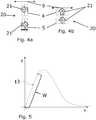
1 eine Schnittansicht durch eine erste Ausführungsform des erfindungsgemäßen Bedienelements;2 eine Schnittansicht durch eine zweite Ausführungsform des erfindungsgemäßen Bedienelements;3 eine Schnittansicht durch eine dritte Ausführungsform des erfindungsgemäßen Bedienelements;4a und4b schematische Darstellungen der erfindungsgemäßen Anordnungsverhältnisse der Permanentmagnetpaare;5 eine schematische Kraft-Weg-Kennlinie6a bis6e weitere schematische Darstellungen der erfindungsgemäßen Anordnungsverhältnisse der Permanentmagnetpaare.
1 a sectional view through a first embodiment of the control element according to the invention;2 a sectional view through a second embodiment of the control element according to the invention;3 a sectional view through a third embodiment of the control element according to the invention;4a and4b schematic representations of the arrangement ratios of the permanent magnet pairs according to the invention;5 a schematic force-displacement curve6a to6e further schematic representations of the arrangement ratios of the permanent magnet pairs according to the invention.
In der in
Die Permanentmagnetpaare
Die
Die zuvor beschriebene Ausgestaltung ist durch eine Kraft-Weg-Kennlinie
Die
Bei der in
Claims (12)
Translated fromGermanPriority Applications (3)
| Application Number | Priority Date | Filing Date | Title |
|---|---|---|---|
| DE102016121425.6ADE102016121425A1 (en) | 2016-11-09 | 2016-11-09 | Control element with touchpad or touchscreen and magnetic reset |
| US15/802,029US10248252B2 (en) | 2016-11-09 | 2017-11-02 | Control element with haptically movable touchpad or touchscreen and with magnetic return |
| CN201711091844.1ACN108062177B (en) | 2016-11-09 | 2017-11-08 | Control element with touch-sensitive movable touch panel or touch screen and magnetic reset |
Applications Claiming Priority (1)
| Application Number | Priority Date | Filing Date | Title |
|---|---|---|---|
| DE102016121425.6ADE102016121425A1 (en) | 2016-11-09 | 2016-11-09 | Control element with touchpad or touchscreen and magnetic reset |
Publications (1)
| Publication Number | Publication Date |
|---|---|
| DE102016121425A1true DE102016121425A1 (en) | 2018-05-09 |
Family
ID=62003225
Family Applications (1)
| Application Number | Title | Priority Date | Filing Date |
|---|---|---|---|
| DE102016121425.6APendingDE102016121425A1 (en) | 2016-11-09 | 2016-11-09 | Control element with touchpad or touchscreen and magnetic reset |
Country Status (3)
| Country | Link |
|---|---|
| US (1) | US10248252B2 (en) |
| CN (1) | CN108062177B (en) |
| DE (1) | DE102016121425A1 (en) |
Families Citing this family (3)
| Publication number | Priority date | Publication date | Assignee | Title |
|---|---|---|---|---|
| KR101784472B1 (en)* | 2015-01-13 | 2017-10-11 | 주식회사 씨케이머티리얼즈랩 | Tactile information supply devide |
| CN108803931B (en)* | 2018-06-11 | 2022-01-18 | 京东方科技集团股份有限公司 | A touch display device and an automobile |
| DE102021123892A1 (en)* | 2021-09-15 | 2023-03-16 | Preh Gmbh | Operating element with movably mounted operating part and improved guide mechanism for parallel guidance of the operating part |
Citations (1)
| Publication number | Priority date | Publication date | Assignee | Title |
|---|---|---|---|---|
| DE102014019041B3 (en)* | 2014-12-18 | 2016-03-24 | Audi Ag | Operating device for a vehicle, in particular a motor vehicle |
Family Cites Families (10)
| Publication number | Priority date | Publication date | Assignee | Title |
|---|---|---|---|---|
| US6822635B2 (en)* | 2000-01-19 | 2004-11-23 | Immersion Corporation | Haptic interface for laptop computers and other portable devices |
| DE102006029506B4 (en)* | 2005-10-28 | 2018-10-11 | Volkswagen Ag | input device |
| CN101150616A (en)* | 2006-09-19 | 2008-03-26 | 北京三星通信技术研究有限公司 | Braille character display device and communication terminal with this device |
| KR101084715B1 (en)* | 2009-05-07 | 2011-11-22 | 한국과학기술원 | Vibration generating module capable of inertia and shock vibration |
| DE102011078932A1 (en)* | 2011-07-11 | 2013-01-17 | Zf Friedrichshafen Ag | induction generator |
| DE102011085146A1 (en)* | 2011-10-25 | 2013-04-25 | Preh Gmbh | Operating element with magnetic reset |
| CN203849640U (en)* | 2014-01-28 | 2014-09-24 | 王莉 | WCDMA (wideband code division multiple access) mobile intelligent original handwriting encrypted tablet personal computer |
| US9632582B2 (en)* | 2014-12-22 | 2017-04-25 | Immersion Corporation | Magnetic suspension system for touch screens and touch surfaces |
| DE102015102346B4 (en)* | 2015-02-19 | 2017-06-01 | Preh Gmbh | Control element with improved actuator for haptic feedback |
| CN204810111U (en)* | 2015-07-10 | 2015-11-25 | 瑞声光电科技(常州)有限公司 | Oscillating motor |
- 2016
- 2016-11-09DEDE102016121425.6Apatent/DE102016121425A1/enactivePending
- 2017
- 2017-11-02USUS15/802,029patent/US10248252B2/enactiveActive
- 2017-11-08CNCN201711091844.1Apatent/CN108062177B/enactiveActive
Patent Citations (1)
| Publication number | Priority date | Publication date | Assignee | Title |
|---|---|---|---|---|
| DE102014019041B3 (en)* | 2014-12-18 | 2016-03-24 | Audi Ag | Operating device for a vehicle, in particular a motor vehicle |
Also Published As
| Publication number | Publication date |
|---|---|
| CN108062177B (en) | 2021-01-05 |
| CN108062177A (en) | 2018-05-22 |
| US10248252B2 (en) | 2019-04-02 |
| US20180129342A1 (en) | 2018-05-10 |
Similar Documents
| Publication | Publication Date | Title |
|---|---|---|
| DE4138405C1 (en) | ||
| DE112017004000T5 (en) | linear actuator | |
| DE102012221107B3 (en) | Operating device for a vehicle component | |
| DE112018003334T5 (en) | Actuator | |
| EP3475788B1 (en) | Touch sensitive input device with improved haptic feedback | |
| DE102008042346A1 (en) | Magnetic yoke, micromechanical component and manufacturing method for a magnetic yoke and a micromechanical component | |
| DE3144002A1 (en) | ACTUATOR FOR IMAGE PLATES | |
| DE102008006832A1 (en) | Electromagnetic membrane microactuator | |
| DE102016121425A1 (en) | Control element with touchpad or touchscreen and magnetic reset | |
| DE10220008A1 (en) | Magnetic spring device with negative stiffness | |
| DE102016223021A1 (en) | Operating device for a motor vehicle and motor vehicle | |
| DE102018108061A1 (en) | Device for generating a haptic feedback | |
| EP2320488A1 (en) | Electromechanical converter with dielectric elastomer | |
| EP3397423B1 (en) | Damping of vibrations of a machine tool | |
| EP1723713A1 (en) | Linear drive device provided with an armature body having a magnet carrier | |
| DE102011103817B4 (en) | Active vibration absorber | |
| EP3380909A2 (en) | Operating unit for a motor vehicle, comprising a drive device for outputting haptic feedback, and motor vehicle | |
| DE102015008763A1 (en) | Motor vehicle operating device with zero position adjusted operating part | |
| DE102015102346B4 (en) | Control element with improved actuator for haptic feedback | |
| DE102018208377A1 (en) | Instrument panel with haptic feedback device | |
| DE202018101900U1 (en) | Touch-sensitive input device with electromagnetic actuator operated in maximum magnetization | |
| DE102019004272B4 (en) | Fan for cooling a precision mechanical component and method for operating such a fan | |
| DE102014002030B4 (en) | Haptic generating device, in particular for an electrical switch and electrical switch with a haptic generating device | |
| EP2920553B1 (en) | Capacitive sensor for detecting a relative movement of two adjacent bodies | |
| EP3608747B1 (en) | Operating device for a vehicle, vehicle |
Legal Events
| Date | Code | Title | Description |
|---|---|---|---|
| R012 | Request for examination validly filed | ||
| R016 | Response to examination communication | ||
| R016 | Response to examination communication |