DE102016120377A1 - Refractometer and method for determining dynamic properties of a sample - Google Patents
Refractometer and method for determining dynamic properties of a sampleDownload PDFInfo
- Publication number
- DE102016120377A1 DE102016120377A1DE102016120377.7ADE102016120377ADE102016120377A1DE 102016120377 A1DE102016120377 A1DE 102016120377A1DE 102016120377 ADE102016120377 ADE 102016120377ADE 102016120377 A1DE102016120377 A1DE 102016120377A1
- Authority
- DE
- Germany
- Prior art keywords
- sample
- measuring
- pressure
- refractometer
- refractive index
- Prior art date
- Legal status (The legal status is an assumption and is not a legal conclusion. Google has not performed a legal analysis and makes no representation as to the accuracy of the status listed.)
- Ceased
Links
- 238000000034methodMethods0.000titleclaimsabstractdescription15
- 238000000594atomic force spectroscopyMethods0.000claimsabstractdescription21
- 230000003287optical effectEffects0.000claimsabstractdescription10
- 238000005259measurementMethods0.000claimsdescription36
- 230000008859changeEffects0.000claimsdescription10
- 230000007704transitionEffects0.000claimsdescription8
- 230000035882stressEffects0.000claimsdescription7
- 230000010355oscillationEffects0.000claimsdescription6
- 230000032683agingEffects0.000claimsdescription4
- 238000011156evaluationMethods0.000claimsdescription4
- 230000000737periodic effectEffects0.000claimsdescription4
- 238000006116polymerization reactionMethods0.000claimsdescription4
- 238000006243chemical reactionMethods0.000claimsdescription3
- 230000009477glass transitionEffects0.000claimsdescription3
- 230000002596correlated effectEffects0.000claimsdescription2
- 230000008961swellingEffects0.000claimsdescription2
- 239000007789gasSubstances0.000description13
- 239000000463materialSubstances0.000description9
- 230000000875corresponding effectEffects0.000description4
- 230000005284excitationEffects0.000description4
- 230000003068static effectEffects0.000description4
- 230000002123temporal effectEffects0.000description4
- 230000008901benefitEffects0.000description3
- 230000001419dependent effectEffects0.000description3
- 230000010363phase shiftEffects0.000description3
- 238000013459approachMethods0.000description2
- 238000006073displacement reactionMethods0.000description2
- 230000000694effectsEffects0.000description2
- 230000002427irreversible effectEffects0.000description2
- 239000007788liquidSubstances0.000description2
- 235000011837pastiesNutrition0.000description2
- 230000001105regulatory effectEffects0.000description2
- 230000002441reversible effectEffects0.000description2
- 238000010008shearingMethods0.000description2
- 239000007787solidSubstances0.000description2
- 239000000126substanceSubstances0.000description2
- 238000002604ultrasonographyMethods0.000description2
- BUHVIAUBTBOHAG-FOYDDCNASA-N(2r,3r,4s,5r)-2-[6-[[2-(3,5-dimethoxyphenyl)-2-(2-methylphenyl)ethyl]amino]purin-9-yl]-5-(hydroxymethyl)oxolane-3,4-diolChemical compoundCOC1=CC(OC)=CC(C(CNC=2C=3N=CN(C=3N=CN=2)[C@H]2[C@@H]([C@H](O)[C@@H](CO)O2)O)C=2C(=CC=CC=2)C)=C1BUHVIAUBTBOHAG-FOYDDCNASA-N0.000description1
- 239000000853adhesiveSubstances0.000description1
- 230000001070adhesive effectEffects0.000description1
- 230000033228biological regulationEffects0.000description1
- 230000005540biological transmissionEffects0.000description1
- 238000012512characterization methodMethods0.000description1
- 239000003638chemical reducing agentSubstances0.000description1
- 238000004140cleaningMethods0.000description1
- 230000006835compressionEffects0.000description1
- 238000007906compressionMethods0.000description1
- 125000004122cyclic groupChemical group0.000description1
- 230000007423decreaseEffects0.000description1
- 238000004925denaturationMethods0.000description1
- 230000036425denaturationEffects0.000description1
- 238000001739density measurementMethods0.000description1
- 238000009795derivationMethods0.000description1
- 238000013461designMethods0.000description1
- 230000005672electromagnetic fieldEffects0.000description1
- 238000001879gelationMethods0.000description1
- 230000003993interactionEffects0.000description1
- 230000036961partial effectEffects0.000description1
- 230000010287polarizationEffects0.000description1
- 230000008569processEffects0.000description1
- 102000004169proteins and genesHuman genes0.000description1
- 108090000623proteins and genesProteins0.000description1
- 230000004044responseEffects0.000description1
- 230000003595spectral effectEffects0.000description1
- 238000005496temperingMethods0.000description1
- 238000012360testing methodMethods0.000description1
- 230000036962time dependentEffects0.000description1
Images

Classifications
- G—PHYSICS
- G01—MEASURING; TESTING
- G01N—INVESTIGATING OR ANALYSING MATERIALS BY DETERMINING THEIR CHEMICAL OR PHYSICAL PROPERTIES
- G01N21/00—Investigating or analysing materials by the use of optical means, i.e. using sub-millimetre waves, infrared, visible or ultraviolet light
- G01N21/17—Systems in which incident light is modified in accordance with the properties of the material investigated
- G01N21/41—Refractivity; Phase-affecting properties, e.g. optical path length
- G01N21/4133—Refractometers, e.g. differential
- G—PHYSICS
- G01—MEASURING; TESTING
- G01N—INVESTIGATING OR ANALYSING MATERIALS BY DETERMINING THEIR CHEMICAL OR PHYSICAL PROPERTIES
- G01N21/00—Investigating or analysing materials by the use of optical means, i.e. using sub-millimetre waves, infrared, visible or ultraviolet light
- G01N21/17—Systems in which incident light is modified in accordance with the properties of the material investigated
- G01N21/1717—Systems in which incident light is modified in accordance with the properties of the material investigated with a modulation of one or more physical properties of the sample during the optical investigation, e.g. electro-reflectance
Landscapes
- Physics & Mathematics (AREA)
- Health & Medical Sciences (AREA)
- Life Sciences & Earth Sciences (AREA)
- Chemical & Material Sciences (AREA)
- Analytical Chemistry (AREA)
- Biochemistry (AREA)
- General Health & Medical Sciences (AREA)
- General Physics & Mathematics (AREA)
- Immunology (AREA)
- Pathology (AREA)
- Investigating Or Analysing Materials By Optical Means (AREA)
Abstract
Translated fromGermanDescription
Translated fromGermanTechnischer BereichTechnical part
Die Erfindung betrifft den Bereich der Messung von dynamischen Eigenschaften einer Probe, insbesondere über die Messung des Brechungsindex mittels eines Refraktometers.The invention relates to the field of measurement of dynamic properties of a sample, in particular via the measurement of the refractive index by means of a refractometer.
Stand der TechnikState of the art
Die Patentschrift
Die Patentschrift
Die Druckschrift
Zusammenfassung der ErfindungSummary of the invention
Technische AufgabeTechnical task
Die der Erfindung zugrunde liegende Aufgabe besteht darin, zumindest einen Nachteil des oben zitierten Stands der Technik zu überwinden. Insbesondere besteht die der Erfindung zugrunde liegende Aufgabe darin, dynamische Eigenschaften eines Materials oder einer Probe über einen einfachen Weg zu ermitteln.The object underlying the invention is to overcome at least one disadvantage of the above cited prior art. In particular, the object underlying the invention is to determine dynamic properties of a material or a sample by a simple way.
Technische LösungTechnical solution
Die Erfindung besteht aus einem Refraktometer umfassend einen Messkörper mit einer Messoberfläche; eine durch die Messoberfläche des Messkörpers abgegrenzte Messkammer zur Aufnahme einer Probe; eine optische Messeinrichtung zur Messung des Brechungsindex der Probe durch den Messkörper; wobei die Messkammer gestaltet ist, um die Probe mechanisch durch eine Druck- und/oder Kraftmodulation beanspruchen zu können, um den Brechungsindex n der Probe dynamisch während der Modulation zu messen.The invention consists of a refractometer comprising a measuring body with a measuring surface; a measuring chamber delimited by the measuring surface of the measuring body for receiving a sample; an optical measuring device for measuring the refractive index of the sample by the measuring body; wherein the measuring chamber is designed to be able to claim the sample mechanically by a pressure and / or force modulation in order to measure the refractive index n of the sample dynamically during the modulation.
Der Messkörper kann aus einem vorzugsweise in einem gegebenen Wellenlängenbereich ganz oder teilweise transparenten Material bestehen.The measuring body can consist of a material that is wholly or partially transparent, preferably in a given wavelength range.
Die Probe kann fest, gel- und/oder pastenförmig oder flüssig sein.The sample may be solid, gel and / or pasty or liquid.
Die Temperatur der Probe kann auch während der Druck- und/oder Kraftmodulation moduliert werden.The temperature of the sample can also be modulated during pressure and / or force modulation.
Der Messkörper kann ein Messprisma sein.The measuring body can be a measuring prism.
In einer weiteren Ausgestaltung ist die Messkammer derart gestaltet, dass die Druck- und/oder Kraftmodulation oszillierend, vorzugsweise gemäß einer periodischen Funktion erfolgt. In a further embodiment, the measuring chamber is designed such that the pressure and / or force modulation takes place oscillating, preferably in accordance with a periodic function.
In einer weiteren Ausgestaltung ist die Messkammer gasdichtend abschließbar, wobei das Refraktometer eine Drucksteuereinrichtung zur Modulierung des Druckes eines Gases in der Messkammer umfasst.In a further embodiment, the measuring chamber can be closed in a gas-tight manner, wherein the refractometer comprises a pressure control device for modulating the pressure of a gas in the measuring chamber.
In einer weiteren Ausgestaltung umfasst die Drucksteuereinrichtung ein erstes elektrisch steuerbares Ventil, das eine Gaszufuhr mit der Messkammer verbindet, und ein zweites elektrisch steuerbares Ventil, das die Messkammer mit der Umgebung verbindet.In a further embodiment, the pressure control device comprises a first electrically controllable valve which connects a gas supply with the measuring chamber, and a second electrically controllable valve which connects the measuring chamber with the environment.
In einer weiteren Ausgestaltung umfasst die Drucksteuereinrichtung einen Druckregler zur Modulierung des Druckes eines Gases in der Messkammer.In a further embodiment, the pressure control device comprises a pressure regulator for modulating the pressure of a gas in the measuring chamber.
In einer weiteren Ausgestaltung umfasst die Messkammer einen Ultraschall-Transducer zur Modulation des Druckes auf der Probe.In a further embodiment, the measuring chamber comprises an ultrasound transducer for modulating the pressure on the sample.
In einer weiteren Ausgestaltung umfasst die Messkammer eine Kraft- und/oder Vorschubsteuereinrichtung mit einem Stempel und mindestens einem Aktuator zur Betätigung des Stempels gegen die Probe.In a further embodiment, the measuring chamber comprises a force and / or feed control device with a punch and at least one actuator for actuating the punch against the sample.
In einer weiteren Ausgestaltung ist der Aktuator elektrisch, elektro-magnetisch, hydraulisch und/oder pneumatisch gestaltet.In a further embodiment, the actuator is designed electrically, electro-magnetically, hydraulically and / or pneumatically.
In einer weiteren Ausgestaltung umfasst die Kraft- und/oder Vorschubsteuereinrichtung einen Sensor zur Messung der durch den Stempel auf die Probe ausgeübten Kraft und/oder einen Sensor zur Messung des Weges des Stempels.In another embodiment, the force and / or feed control device comprises a sensor for measuring the force exerted by the punch on the sample force and / or a sensor for measuring the path of the punch.
In einer weiteren Ausgestaltung ist die Kraft- und/oder Vorschubsteuereinrichtung derart gestaltet, dass die durch den Stempel auf der Probe ausübbare Kraft nicht parallel zur Längsachse des Stempels verläuft.In a further embodiment, the force and / or feed control device is designed such that the force exerted by the punch on the sample does not run parallel to the longitudinal axis of the punch.
In einer weiteren Ausgestaltung ist die Kraftsteuereinrichtung derart gestaltet, dass die durch den Stempel auf der Probe ausübbare Kraft drehend um die Längsachse des Stempels ist.In a further refinement, the force control device is designed in such a way that the force that can be exerted on the sample by the punch is rotating about the longitudinal axis of the punch.
In einer weiteren Ausgestaltung umfasst das Refraktometer eine Auswerteeinheit, die derart gestaltet ist, dass sie basierend auf der Messung des Brechungsindex während der Kraft- und/oder Druckmodulation die Kompressibilität k der Probe ermittelt.In another embodiment, the refractometer comprises an evaluation unit which is designed such that it determines the compressibility k of the sample based on the measurement of the refractive index during the force and / or pressure modulation.
Die Erfindung besteht auch aus einem Verfahren zur Messung von Eigenschaften einer Probe, umfassend die folgenden Schritte: Einführung einer Probe in ein Refraktometer; Messung des Brechungsindex der Probe mit dem Refraktometer, wobei das Refraktometer gemäß der Erfindung ausgeführt ist; die Probe durch eine modulierte Kraft und/oder einen modulierten Druck während der Brechungsindexmessung beansprucht wird, und der Brechungsindex n dynamisch in Abhängigkeit von der Druck- und/oder Kraftmodulation ermittelt wird.The invention also consists of a method of measuring properties of a sample comprising the steps of: introducing a sample into a refractometer; Measuring the refractive index of the sample with the refractometer, wherein the refractometer is made according to the invention; the sample is stressed by a modulated force and / or a modulated pressure during the refractive index measurement, and the refractive index n is determined dynamically as a function of the pressure and / or force modulation.
In einer weiteren Ausgestaltung wird die dynamische Kompressibilität k der Probe anhand des dynamischen Brechungsindex n unter Heranziehung eines optomechanischen Modells, vorzugsweise der Lorentz-Lorenz Gleichung, ermittelt. Das optomechanische Modell stellt Zusammenhänge zwischen Brechungsindex, Dichte und Refraktivität her. Das optomechanische Modell kann z.B. die Relationen nach Gladstone-Dale, Beysens und/oder Proutiere umfassen.In a further embodiment, the dynamic compressibility k of the sample is determined on the basis of the dynamic refractive index n using an optomechanical model, preferably the Lorentz-Lorenz equation. The optomechanical model establishes relationships between refractive index, density and refractivity. The optomechanical model may e.g. the relations to Gladstone-Dale, Beysens and / or Proutiere include.
In einer weiteren Ausgestaltung wird die Dichte ρ der Probe während der Druck- und/oder Kraftmodulation anhand des Wegs oder der Volumsänderung aufgrund der Druck- und/oder Kraftmodulation ermittelt.In a further embodiment, the density ρ of the sample is determined during the pressure and / or force modulation on the basis of the path or the volume change on the basis of the pressure and / or force modulation.
In einer weiteren Ausgestaltung wird die dynamische spezifische Refraktivität r der Probe anhand des dynamischen Brechungsindex n und der Dichte ρ unter Heranziehung eines optomechanischen Modells, vorzugsweise der Lorentz-Lorenz Gleichung ermittelt. Das optomechanische Modell stellt Zusammenhänge zwischen Brechungsindex, Dichte und Refraktivität her. Das optomechanische Modell kann z.B. die Relationen nach Gladstone-Dale, Beysens und/oder Proutiere umfassen.In a further embodiment, the dynamic specific refractivity r of the sample is determined on the basis of the dynamic refractive index n and the density ρ using an optomechanical model, preferably the Lorentz-Lorenz equation. The optomechanical model establishes relationships between refractive index, density and refractivity. The optomechanical model may e.g. the relations to Gladstone-Dale, Beysens and / or Proutiere include.
In einer weiteren Ausgestaltung findet in der Probe eine chemische Reaktion, vorzugsweise eine Polymerisationsreaktion, und/oder eine Quellung und/oder eine Alterung und/oder ein Phasen- oder Glasübergang während der Messung des Brechungsindex statt, und die Veränderung der dynamischen spezifischen Refraktivität r der Probe stellt mikroskopische Informationen und die Veränderung der Dichte ρ der Probe makroskopische Informationen bereit.In a further embodiment, a chemical reaction, preferably a polymerization reaction, and / or a swelling and / or an aging and / or a phase or glass transition during the measurement of the refractive index takes place in the sample, and the change in the dynamic specific refractivity r of the Sample provides microscopic information and changing the density ρ of the sample provides macroscopic information.
In einer weiteren Ausgestaltung findet ein Gelierübergang in der Probe während der Messung des Brechungsindex statt und die Druck- und/oder Kraftmodulation umfasst eine modulierte scherende Oszillation und/oder eine modulierte Drehoszillation. In a further refinement, a gelling transition takes place in the sample during the measurement of the refractive index, and the pressure and / or force modulation comprises a modulated shearing oscillation and / or a modulated rotational oscillation.
In einer weiteren Ausgestaltung werden ein oder mehrere Signale, die den Verlauf des Brechungsindex n, der Dichte ρ und/oder der spezifischen Refraktivität r wiederspiegeln, demoduliert, und ein Peak in dem Imaginärteil der Demodulation wird beobachtet und mit dem Übergang korreliert.In another embodiment, one or more signals reflecting the shape of refractive index n, density ρ and / or specific refractivity r are demodulated, and a peak in the imaginary part of the demodulation is observed and correlated with the transition.
In einer weiteren Ausgestaltung emittiert und/oder detektiert die optische Messeinrichtung selektiv s-oder p-polarisierte Strahlen zur Messung von Anisotropie in der Probe.In a further embodiment, the optical measuring device selectively emits and / or detects s-polarized or p-polarized beams for measuring anisotropy in the sample.
Vorteile der ErfindungAdvantages of the invention
Die mechanischen Eigenschaften der Probe und deren zeitliche Veränderungen werden durch die Maßnahmen der Erfindung messbar. Die Erfindung eignet sich insbesondere auch für Proben, bei denen die üblichen Messverfahren scheitern. Die modulierte Messung erlaubt es auch langsame Prozesse, wie z. B. Alterungsprozesse, oder chemische Veränderungen von Proben (bspw. Kleber) zu verfolgen. Die mit der druckmodulierten Brechungsindexmessung ermittelte dynamische Kompressibilität zeichnet sich im Vergleich zur statischen Kompressibilität der Gleichgewichts- oder reversiblen Thermodynamik dadurch aus, dass sie Informationen über zeitliche Phänomene der irreversiblen Thermodynamik wiedergibt. Die modulierte Messung erlaubt es makroskopische sowie mikroskopische, dynamische Informationen über die Probe zu sammeln.The mechanical properties of the sample and its temporal changes are measurable by the measures of the invention. The invention is also particularly suitable for samples in which the usual measuring methods fail. The modulated measurement also allows slow processes, such. As aging processes, or to monitor chemical changes of samples (eg adhesive). The dynamic compressibility determined with the pressure-modulated refractive index measurement is distinguished from the static compressibility of the equilibrium or reversible thermodynamics in that it reproduces information about temporal phenomena of irreversible thermodynamics. The modulated measurement allows macroscopic as well as microscopic, dynamic information on the sample to be collected.
Figurenlistelist of figures
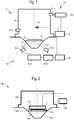
1 zeigt eine schematische Draufsicht eines Refraktometers gemäß einem ersten Ausführungsbeispiel der Erfindung.1 shows a schematic plan view of a refractometer according to a first embodiment of the invention.2 zeigt eine schematische Draufsicht einer Messkammer eines Refraktometers gemäß einem zweiten Ausführungsbeispiel der Erfindung.2 shows a schematic plan view of a measuring chamber of a refractometer according to a second embodiment of the invention.3 zeigt eine schematische Draufsicht eines Refraktometers gemäß einem dritten Ausführungsbeispiel der Erfindung.3 shows a schematic plan view of a refractometer according to a third embodiment of the invention.4 zeigt eine schematische Draufsicht einer Messkammer eines Refraktometers gemäß einem vierten Ausführungsbeispiel der Erfindung.4 shows a schematic plan view of a measuring chamber of a refractometer according to a fourth embodiment of the invention.
Beschreibung der AusführungsbeispieleDescription of the embodiments
Das Messprisma
Die Messkammer
Die optische Messeinrichtung
Der Aufbau der oben beschriebenen optischen Messeinrichtung
Da der Brechungsindex der Probe relativ zu jenem des Messprismas gemessen wird, ist es notwendig die Eigenschaften des Prismas (Brechungsindex, Druck- bzw. Kraft- Verhalten usw.) gut zu kennen, um die dynamischen Eigenschaften der Proben messbar zu machen. Neben der bevorzugten Messung des Brechungsindex in Totalreflexion ist die Brechungsindexmessung in einem Messaufbau mit Transmissionsgeometrie realisierbar.Since the refractive index of the sample is measured relative to that of the measuring prism, it is necessary to know well the properties of the prism (refractive index, pressure or force behavior, etc.) in order to make the dynamic properties of the samples measurable. In addition to the preferred measurement of the refractive index in total reflection, the refractive index measurement can be implemented in a measurement setup with transmission geometry.
Im oben beschriebenen Refraktometer wird die Probe während der Brechungsindexmessung mechanisch durch eine Druckmodulation beansprucht. Unter einer Modulation ist in der allgemeinsten Form eine periodische Änderung einer Größe zu verstehen. Die Modulation kann verschiedenartig sein und kann zum Beispiel einen rechteckigen, dreieckigen, sinusförmigen oder polynomförmigen zeitlichen Verlauf oder Kombinationen daraus aufweisen. Die oben beschriebene Drucksteuereinrichtung ist eher für eine Rechteckmodulation geeignet. Anstatt von zwei Ventilen, die lediglich auf- und zugemacht werden können, kann die Drucksteuereinrichtung einen gesteuerten Druckregler aufweisen, der beliebige Modulationen generieren kann.In the refractometer described above, the sample is mechanically stressed during the refractive index measurement by a pressure modulation. By modulation is meant in the most general form a periodic change of a quantity. The modulation may be varied and may, for example, have a rectangular, triangular, sinusoidal or polynomial time course or combinations thereof. The pressure control device described above is more suitable for rectangular modulation. Instead of two valves that can only be opened and closed, the pressure control device may have a controlled pressure regulator that can generate any modulations.
Über die Relation zwischen Brechungsindex n und Dichte p erhält man im Falle einer Druckmodulation die dynamische Kompressibilität k als neue, mit einem Refraktometer messbare Materialeigenschaft. In einem einfachen, theoretischen Modell, z. B. wird die Lorentz-Lorenz Relation


In komplexer Schreibweise lautet die Gleichung
Dabei ist unter 〈n〉 der über eine Modulationsperiode gemittelte Brechungsindex zu verstehen. Eine separate Dichtemessung ist dabei nicht notwendig, kann aber optional erfolgen, um genauere Messergebnisse zu erlangen. Anstelle der Lorentz-Lorenz Relation kann auch ein anderes, vergleichbares optomechanisches Modell verwendet werden. Diese vergleichbaren optomechanischen Modelle stellen allesamt Zusammenhänge zwischen Brechungsindex, Dichte und Refraktivität her und beinhalten die Methode, durch eine Ableitung der jeweils zugrundeliegenden Gleichungen nach dem Druck und/oder der Kraft die entsprechenden Formeln für ein thermooptisches Modell, d.h. für den Zusammenhang zwischen Kompressibilität und Brechungsindex, zur Verfügung zu stellen. Dem Fachmann bekannte optomechanische Modelle sind beispielsweise die Relationen nach Gladstone-Dale, Beysens oder Proutiere.In this case, <n> is to be understood as the refractive index averaged over a modulation period. A separate density measurement is not necessary, but can optionally be done to obtain more accurate measurement results. Instead of the Lorentz-Lorenz relation, another comparable optomechanical model can be used. These comparable optomechanical models all produce relationships between refractive index, density, and refractivity and include the method, by deriving the underlying equations after the pressure and / or force, the corresponding formulas for a thermo-optical model, ie for the relationship between compressibility and refractive index , to To make available. Optomechanical models known to the person skilled in the art are, for example, the relations according to Gladstone-Dale, Beysens or Proutiere.
Im allgemeineren Fall, dass die spezifische Refraktivität r druck- bzw. kraftabhängig ist, ergibt sich z. B. in einem einfachen Modell nach Ableitung der Lorentz-Lorenz Relation der Zusammenhang in komplexer Schreibweise:
Bei durchgehender Messung des Brechungsindex wird eine Probe einer bekannten mechanischen, oszillierenden Anregung, nachfolgend mit
Als mechanische Anregung kann eine isotrope oder gerichtete Druck-/ Kraft- oder Deformationsmodulation angewendet werden, es ist aber auch die Applikation von modulierten Torsionskräften oder Drehdeformationen denkbar. Bei Auswahl einer kleinen Amplitude pampl kommt es zu einer linearen Antwort im Brechungsindex

Die mit der druckmodulierten Brechungsindexmessung ermittelte dynamische Kompressibilität zeichnet sich im Vergleich zur statischen Kompressibilität der Gleichgewichts- oder reversiblen Thermodynamik dadurch aus, dass sie Informationen über zeitliche Phänomene der irreversiblen Thermodynamik wiedergibt. Dies ist bei realen Applikationen von besonderem Interesse, da z. B. eine Beanspruchung eines Materials typischerweise nicht im thermischen Gleichgewicht verläuft, daher sämtliche Materialeigenschaften dynamisch belegt sind. Für hinreichend lange Perioden nähert sich in der Regel die dynamische Kompressibilität k der statischen Kompressibilität kstat an.The dynamic compressibility determined with the pressure-modulated refractive index measurement is distinguished from the static compressibility of the equilibrium or reversible thermodynamics in that it reproduces information about temporal phenomena of irreversible thermodynamics. This is in real applications of particular interest because z. For example, a stress on a material is typically not in thermal equilibrium, so all material properties are dynamically occupied. For sufficiently long periods, as a rule, the dynamic compressibility k approaches the static compressibility kstat .
Das Refraktometer
Das Refraktometer der
Die Kraftsteuereinrichtung
Der Aktuator oder zumindest einer der Aktuatoren kann derart ausgewählt werden, dass er aus seiner Steuergröße direkt eine quantifizierbare Kraft erzeugt. Der Vorteil von solchen Aktuatoren ist, dass bei bekannter Kontaktfläche eine Modulation der Steuergröße direkt in eine Druckmodulation umgesetzt wird. Bei geringeren Genauigkeitsanforderungen kann dann gegebenenfalls auf eine separate Kraftmessung verzichtet werden. Soll anstatt des Druckes die Kompressionsdeformation moduliert werden, so kann die Position des Andruckstempels mit einem geeigneten Sensor
Der Aktuator oder zumindest einer der Aktuatoren kann derart ausgewählt werden, dass er aus seiner Steuergröße direkt einen quantifizierbaren Vorschub erzeugt. Ein Beispiel ist ein mit einem Schritt- oder Servomotor angetriebener Spindeltrieb oder ein linearer Motor. Bei geringeren Genauigkeitsanforderungen kann auf eine separate Wegmessung verzichtet werden. Um eine Druckmodulation zu erzeugen muss die auf die Probe ausgeübte Kraft mit einem entsprechenden Sensor
Der Sensor
Bei einer uniaxialen Kraftapplikation ergibt sich ein weiterer Vorteil, wenn zusätzlich zur Brechungsindexoszillation und der Anpresskraft auch die lineare Deformation der Probe gemessen wird. Aus Anpressdruck σ und der linearen Deformation ε der Probe erhält man dann den Elastizitätsmodul E über die Relation σ = E · ε . Für isotrope homogene Proben lässt sich dann über die Verbindung zwischen Kompressibilität und Elastizitätsmodul
Obige Gleichungen zur Kompressibilität wurden für eine Druckmodulation ermittelt. Jedoch sind sie prinzipiell erweiterbar für andere Arten der modulierten mechanischen Anregung. In diesem Fall gilt die Formel


Die Kraftsteuereinrichtung
Bei dieser Gestaltung lässt sich ein Gelierübergang einer Probe während der Polymerisation messen. Der Gelierpunkt ist dabei als Peak im Imaginärteil der Demodulation der Größen


Wird des Weiteren die Probentemperatur T oder ein äquivalenter physikalischer oder chemischer Parameter (z.B. Feuchtigkeit, elektromagnetisches Feld, pH-Wert) über ein bekanntes Programm bei durchgehender Druck-/Kraftmodulation variiert, können auch Phasen- und Glasübergänge gemessen werden. Diese manifestieren sich als Peak in der Phasenverschiebung ϕ(T) beziehungsweise im Imaginärteil von

Die Applikation einer uniaxialen Druck- oder Kraftmodulation kann bei isotropen Proben zur Spannungsdoppelbrechung führen und der Brechungsindex ist tensoriell zu interpretieren. Bei Spannungsdoppelbrechung gilt im Allgemeinen für die Brechungsindizes der Hauptachsen:


Wobei nunbelastet den Brechungsindex der unbelasteten Probe wiedergibt, C1 und C2 die spannungsoptischen Koeffizienten darstellen und σii die Normalspannungen entlang der Hauptachsen repräsentiert. Erfolgt die Druck-/Kraftmodulation z.B. entlang der x3-Achse, senkrecht zur Messoberfläche, erhält man über Selektion der s-Polarisation den Brechungsindex des ordentlichen Strahls n1 = n2 = n0. Bei Selektion der p-Polarisation ist der Brechungsindex abhängig vom Einfallswinkel, jedoch nähert er sich am Winkel der Totalreflexion dem Brechungsindex des außerordentlichen Strahls n3 = na. Die dynamische Brechungsindexmessung liefert nach der Demodulation jeweils direkt


ZITATE ENTHALTEN IN DER BESCHREIBUNG QUOTES INCLUDE IN THE DESCRIPTION
Diese Liste der vom Anmelder aufgeführten Dokumente wurde automatisiert erzeugt und ist ausschließlich zur besseren Information des Lesers aufgenommen. Die Liste ist nicht Bestandteil der deutschen Patent- bzw. Gebrauchsmusteranmeldung. Das DPMA übernimmt keinerlei Haftung für etwaige Fehler oder Auslassungen.This list of the documents listed by the applicant has been generated automatically and is included solely for the better information of the reader. The list is not part of the German patent or utility model application. The DPMA assumes no liability for any errors or omissions.
Zitierte PatentliteraturCited patent literature
- EP 2266693 A1 [0002]EP 2266693 A1 [0002]
- WO 2012/025346 A1 [0003]WO 2012/025346 A1 [0003]
- US 4702604 [0004]US 4702604 [0004]
Claims (20)
Translated fromGermanPriority Applications (4)
| Application Number | Priority Date | Filing Date | Title |
|---|---|---|---|
| DE102016120377.7ADE102016120377A1 (en) | 2016-10-25 | 2016-10-25 | Refractometer and method for determining dynamic properties of a sample |
| CN201780065959.5ACN109863389A (en) | 2016-10-25 | 2017-10-11 | For measuring the refractometer and method of the dynamic characteristic of sample |
| PCT/EP2017/075928WO2018077616A1 (en) | 2016-10-25 | 2017-10-11 | Refractometer and method for determining dynamic properties of a sample |
| US16/344,296US20190271643A1 (en) | 2016-10-25 | 2017-10-11 | Refractometer and Method for Determining Dynamic Properties of a Sample |
Applications Claiming Priority (1)
| Application Number | Priority Date | Filing Date | Title |
|---|---|---|---|
| DE102016120377.7ADE102016120377A1 (en) | 2016-10-25 | 2016-10-25 | Refractometer and method for determining dynamic properties of a sample |
Publications (1)
| Publication Number | Publication Date |
|---|---|
| DE102016120377A1true DE102016120377A1 (en) | 2018-04-26 |
Family
ID=60080809
Family Applications (1)
| Application Number | Title | Priority Date | Filing Date |
|---|---|---|---|
| DE102016120377.7ACeasedDE102016120377A1 (en) | 2016-10-25 | 2016-10-25 | Refractometer and method for determining dynamic properties of a sample |
Country Status (4)
| Country | Link |
|---|---|
| US (1) | US20190271643A1 (en) |
| CN (1) | CN109863389A (en) |
| DE (1) | DE102016120377A1 (en) |
| WO (1) | WO2018077616A1 (en) |
Families Citing this family (1)
| Publication number | Priority date | Publication date | Assignee | Title |
|---|---|---|---|---|
| US11175224B2 (en)* | 2018-08-06 | 2021-11-16 | Government Of The United States Of America, As Represented By The Secretary Of Commerce | Optical refraction barometer |
Citations (4)
| Publication number | Priority date | Publication date | Assignee | Title |
|---|---|---|---|---|
| US4702604A (en) | 1985-12-31 | 1987-10-27 | L'universite Du Quebec A Trois-Rivieres | Precise determination of the compressibility factor of a gas from refractive index measurements |
| EP2266693A1 (en) | 2009-06-26 | 2010-12-29 | Mettler-Toledo AG | Cover unit |
| WO2012025346A1 (en) | 2010-08-23 | 2012-03-01 | Université Du Luxembourg | Temperature modulated refractive index measurement |
| CN104990500A (en)* | 2015-07-03 | 2015-10-21 | 郑州轻工业学院 | Apparatus and method for detecting size and refractive index of material in diamond anvil cell |
Family Cites Families (18)
| Publication number | Priority date | Publication date | Assignee | Title |
|---|---|---|---|---|
| US2885922A (en)* | 1953-10-01 | 1959-05-12 | Phillips Petroleum Co | Optical analyzer for fluids |
| US4451147A (en)* | 1981-08-31 | 1984-05-29 | Karel Dobes | Refractometer |
| US4844608A (en)* | 1987-03-23 | 1989-07-04 | American Telephone And Telegraph Company At&T Bell Laboratories | Solution monitoring procedure |
| US5757477A (en)* | 1995-04-17 | 1998-05-26 | Ceram Optec Industries Inc | Real time monitoring of medium parameters |
| US5926284A (en)* | 1997-04-30 | 1999-07-20 | Fuji Photo Film Co., Ltd. | Surface plasmon sensor |
| JP2004150923A (en)* | 2002-10-30 | 2004-05-27 | Atago:Kk | Refractometer |
| US7419707B2 (en)* | 2005-02-21 | 2008-09-02 | Fujifilm Corporation | Coating composition for the formation of low refractive index layer, antireflection film, polarizing plate and liquid crystal display device |
| US7461547B2 (en)* | 2005-04-29 | 2008-12-09 | Schlumberger Technology Corporation | Methods and apparatus of downhole fluid analysis |
| TWI422913B (en)* | 2005-08-26 | 2014-01-11 | Konica Minolta Opto Inc | A thin film and a method for manufacturing the same, and a polarizing plate and a liquid crystal display device using the same |
| US7456942B1 (en)* | 2006-10-17 | 2008-11-25 | Curley Michael J | Dynamic refractometer |
| JP4228026B2 (en)* | 2007-02-28 | 2009-02-25 | 日東電工株式会社 | Backlight system and optical sheet with adhesive |
| US8673827B1 (en)* | 2007-11-28 | 2014-03-18 | Los Alamos National Security, Llc | Method of analysis of polymerizable monomeric species in a complex mixture |
| JP2009229323A (en)* | 2008-03-24 | 2009-10-08 | Canon Inc | Specimen information obtaining apparatus and method |
| US8542353B2 (en)* | 2010-09-30 | 2013-09-24 | Precision Energy Services, Inc. | Refractive index sensor for fluid analysis |
| DE102015106805A1 (en)* | 2015-04-30 | 2016-11-03 | Anton Paar Optotec Gmbh | Temperature calibration for meter |
| DE102015106795A1 (en)* | 2015-04-30 | 2016-11-03 | Anton Paar Optotec Gmbh | Wavelength calibration for refractometer |
| US10078048B2 (en)* | 2016-01-27 | 2018-09-18 | Corning Incorporated | Refractometer assemblies, methods of calibrating the same, and methods of determining unknown refractive indices using the same |
| US10883338B2 (en)* | 2017-02-27 | 2021-01-05 | Onesubsea Ip Uk Limited | Polymagnetic flow control valves |
- 2016
- 2016-10-25DEDE102016120377.7Apatent/DE102016120377A1/ennot_activeCeased
- 2017
- 2017-10-11USUS16/344,296patent/US20190271643A1/ennot_activeAbandoned
- 2017-10-11WOPCT/EP2017/075928patent/WO2018077616A1/ennot_activeCeased
- 2017-10-11CNCN201780065959.5Apatent/CN109863389A/enactivePending
Patent Citations (4)
| Publication number | Priority date | Publication date | Assignee | Title |
|---|---|---|---|---|
| US4702604A (en) | 1985-12-31 | 1987-10-27 | L'universite Du Quebec A Trois-Rivieres | Precise determination of the compressibility factor of a gas from refractive index measurements |
| EP2266693A1 (en) | 2009-06-26 | 2010-12-29 | Mettler-Toledo AG | Cover unit |
| WO2012025346A1 (en) | 2010-08-23 | 2012-03-01 | Université Du Luxembourg | Temperature modulated refractive index measurement |
| CN104990500A (en)* | 2015-07-03 | 2015-10-21 | 郑州轻工业学院 | Apparatus and method for detecting size and refractive index of material in diamond anvil cell |
Non-Patent Citations (1)
| Title |
|---|
| KURYAEVA, R.G.; KIRKINSKII, V.A.: Influence of high pressure on the refractive index and density of tholeiite basalt glass. In: Phys Chem Minerals, Vol. 25, 1997, S. 48-54.* |
Also Published As
| Publication number | Publication date |
|---|---|
| CN109863389A (en) | 2019-06-07 |
| WO2018077616A1 (en) | 2018-05-03 |
| US20190271643A1 (en) | 2019-09-05 |
Similar Documents
| Publication | Publication Date | Title |
|---|---|---|
| N’jock et al. | A criterion to identify sinking-in and piling-up in indentation of materials | |
| EP3004827B1 (en) | Measuring device and method for ascertaining a pressure map | |
| DE102011055953B3 (en) | Method for determination of three dimensional deformation of sample made of e.g. wood during introduction of force and/or moment in housing of test equipment, involves carrying out image correlations for determination of sample deformation | |
| DE68915264T2 (en) | Device for crystallographic examinations under high pressure. | |
| DE3623664A1 (en) | METHOD AND DEVICE FOR MEASURING GAS PROPERTIES | |
| DE10209245B4 (en) | Device and method for the detection of microorganisms | |
| Andrews | Stresses at a crack in an elastomer | |
| DE102016120377A1 (en) | Refractometer and method for determining dynamic properties of a sample | |
| Osaki et al. | Flow birefringence of polymer solutions in time‐dependent field. Relation between normal and shear stresses on application of step‐shear strain | |
| DE19706744C2 (en) | Device for measuring viscoelastic properties of bodies | |
| DE112012001688B4 (en) | Bellows-operated infrared table | |
| EP3754329A1 (en) | Hydrogen sensor and method for producing the same, measuring device and method for measuring hydrogen concentration | |
| Fried | Some observations on photoelastic materials stressed beyond the elastic limit | |
| Titus et al. | Determination of elastic moduli of polymeric materials using microhardness indentation | |
| DE60224538T2 (en) | MEASURING DEVICE FOR THE INVESTIGATION OF A COMPRESSIBLE WEAVE | |
| EP1000338B1 (en) | Method for detecting rheological properties of a material | |
| EP0919802B1 (en) | Process for testing the property of a coating | |
| DE102019109682B4 (en) | Method for calibrating a pressure measuring instrument by means of a pressure calibration device | |
| EP2028462B1 (en) | Device and method for qualitative determination of the cavitation energy of ultrasound in containers | |
| DE102021213382A1 (en) | METHOD OF PREDICTING A LIFETIME OF A MATERIAL | |
| Heinrich et al. | Data Preprocessing of In Situ Laser‐Backscattering Measurements | |
| DE102013014807B3 (en) | Arrangement and method for the synchronous determination of the modulus of shear and the Poisson number on samples of elastically isotropic and anisotropic materials | |
| DE19831622B4 (en) | Process for the characterization of mechanical stress states in flat materials and device for carrying out the process | |
| Ford et al. | Spatially-resolved volume monitoring of adhesive cure using correlated-image optical coherence tomography | |
| Radebe | Development of Rheo-IR: Combination of a Strain-Controlled Rheometer with an IR Spectrometer for in-situ Mechanical and Chemical Analysis of Cement Paste |
Legal Events
| Date | Code | Title | Description |
|---|---|---|---|
| R012 | Request for examination validly filed | ||
| R016 | Response to examination communication | ||
| R002 | Refusal decision in examination/registration proceedings | ||
| R003 | Refusal decision now final |