DE102016116399B4 - Sitting or lying device for magnetic field therapy - Google Patents
Sitting or lying device for magnetic field therapyDownload PDFInfo
- Publication number
- DE102016116399B4 DE102016116399B4DE102016116399.6ADE102016116399ADE102016116399B4DE 102016116399 B4DE102016116399 B4DE 102016116399B4DE 102016116399 ADE102016116399 ADE 102016116399ADE 102016116399 B4DE102016116399 B4DE 102016116399B4
- Authority
- DE
- Germany
- Prior art keywords
- applicator device
- applicator
- sitting
- lying
- designed
- Prior art date
- Legal status (The legal status is an assumption and is not a legal conclusion. Google has not performed a legal analysis and makes no representation as to the accuracy of the status listed.)
- Active
Links
- 238000002560therapeutic procedureMethods0.000titleclaimsabstractdescription12
- 238000001816coolingMethods0.000claimsabstractdescription42
- 239000002826coolantSubstances0.000claimsabstractdescription14
- 230000008859changeEffects0.000claimsabstractdescription6
- 230000005672electromagnetic fieldEffects0.000claimsabstractdescription6
- 230000002123temporal effectEffects0.000claimsabstractdescription5
- 230000004118muscle contractionEffects0.000claimsabstractdescription4
- 230000007246mechanismEffects0.000claimsdescription12
- 230000000638stimulationEffects0.000claimsdescription10
- 210000000746body regionAnatomy0.000claimsdescription9
- 238000006073displacement reactionMethods0.000claimsdescription9
- 210000003205muscleAnatomy0.000description8
- 210000002569neuronAnatomy0.000description5
- 210000003903pelvic floorAnatomy0.000description4
- 206010021639IncontinenceDiseases0.000description3
- 230000005674electromagnetic inductionEffects0.000description3
- 230000006870functionEffects0.000description3
- 239000007788liquidSubstances0.000description3
- 210000001519tissueAnatomy0.000description3
- 206010066218Stress Urinary IncontinenceDiseases0.000description2
- 210000000663muscle cellAnatomy0.000description2
- 210000004197pelvisAnatomy0.000description2
- 230000000284resting effectEffects0.000description2
- 208000022170stress incontinenceDiseases0.000description2
- 208000000921Urge Urinary IncontinenceDiseases0.000description1
- 230000008901benefitEffects0.000description1
- 238000007664blowingMethods0.000description1
- 239000003990capacitorSubstances0.000description1
- 210000000170cell membraneAnatomy0.000description1
- 230000035606childbirthEffects0.000description1
- 230000013872defecationEffects0.000description1
- 230000007812deficiencyEffects0.000description1
- 230000000694effectsEffects0.000description1
- 230000005684electric fieldEffects0.000description1
- 230000009986erectile functionEffects0.000description1
- 239000012530fluidSubstances0.000description1
- 230000003054hormonal effectEffects0.000description1
- 239000000463materialSubstances0.000description1
- 239000012528membraneSubstances0.000description1
- 230000028161membrane depolarizationEffects0.000description1
- 230000027939micturitionEffects0.000description1
- 210000001611motor endplateAnatomy0.000description1
- 210000000056organAnatomy0.000description1
- 230000000399orthopedic effectEffects0.000description1
- 230000035935pregnancyEffects0.000description1
- 230000000069prophylactic effectEffects0.000description1
- 238000011471prostatectomyMethods0.000description1
- 210000005070sphincterAnatomy0.000description1
- 230000000087stabilizing effectEffects0.000description1
- 230000003068static effectEffects0.000description1
- 210000000225synapseAnatomy0.000description1
- 230000001225therapeutic effectEffects0.000description1
- 230000001052transient effectEffects0.000description1
- 206010046494urge incontinenceDiseases0.000description1
- XLYOFNOQVPJJNP-UHFFFAOYSA-NwaterSubstancesOXLYOFNOQVPJJNP-UHFFFAOYSA-N0.000description1
Images


Classifications
- A—HUMAN NECESSITIES
- A61—MEDICAL OR VETERINARY SCIENCE; HYGIENE
- A61N—ELECTROTHERAPY; MAGNETOTHERAPY; RADIATION THERAPY; ULTRASOUND THERAPY
- A61N2/00—Magnetotherapy
- A61N2/02—Magnetotherapy using magnetic fields produced by coils, including single turn loops or electromagnets
- A—HUMAN NECESSITIES
- A61—MEDICAL OR VETERINARY SCIENCE; HYGIENE
- A61N—ELECTROTHERAPY; MAGNETOTHERAPY; RADIATION THERAPY; ULTRASOUND THERAPY
- A61N2/00—Magnetotherapy
- A61N2/06—Magnetotherapy using magnetic fields produced by permanent magnets
Landscapes
- Health & Medical Sciences (AREA)
- Engineering & Computer Science (AREA)
- Biomedical Technology (AREA)
- Nuclear Medicine, Radiotherapy & Molecular Imaging (AREA)
- Radiology & Medical Imaging (AREA)
- Life Sciences & Earth Sciences (AREA)
- Animal Behavior & Ethology (AREA)
- General Health & Medical Sciences (AREA)
- Public Health (AREA)
- Veterinary Medicine (AREA)
- Magnetic Treatment Devices (AREA)
Abstract
Translated fromGerman
Description
Translated fromGermanDie Erfindung betrifft eine Sitz- oder Liegevorrichtung für eine Magnetfeldtherapie mit einer Fläche zum Aufnehmen für eine zu behandelnde Person, und mit einer ersten Applikatoreinrichtung zum Erzeugen eines Magnetfeldes, die mit einer Positioniereinrichtung relativ zu der Fläche verstellbar ist, wobei die erste Applikatoreinrichtung in einer Rückenlehne und eine zweite Applikatoreinrichtung in einem Sitzelement angeordnet ist.The invention relates to a sitting or lying device for magnetic field therapy with a surface for receiving a person to be treated, and with a first applicator device for generating a magnetic field, which is adjustable with a positioning device relative to the surface, wherein the first applicator device is arranged in a backrest and a second applicator device is arranged in a seat element.
Entsprechende Vorrichtungen sind aus der
Hierbei ist von Nachteil, dass die Applikatoreinrichtungen fest und unveränderbar mit der Vorrichtung verbunden sind. Hierdurch ist die Einstellbarkeit des Magnetfeldes erheblich eingeschränkt bzw. unmöglich. Beispielsweise ist eine individuelle Einstellung des Magnetfeldes auf eine zu behandelnde Person oder eine zu behandelnde Körperregion der zu behandelnden Person behindert.The disadvantage here is that the applicator devices are firmly and unchangeably connected to the device. This means that the adjustability of the magnetic field is significantly limited or even impossible. For example, an individual adjustment of the magnetic field to a person or a body region of the person to be treated is hindered.
Es ist daher die der Erfindung zugrundeliegende Aufgabe, eine Sitz- oder Liegevorrichtung der eingangs genannten Art derart weiterzuentwickeln, dass die Einstellbarkeit und/oder Justierung des Magnetfeldes der mindestens einen Applikatoreinrichtung verbessert ist. Insbesondere soll eine alternative Ausführungsform bereitgestellt werden.It is therefore the object underlying the invention to further develop a sitting or lying device of the type mentioned at the outset in such a way that the adjustability and/or adjustment of the magnetic field of the at least one applicator device is improved. In particular, an alternative embodiment is to be provided.
Die der Erfindung zugrundeliegende Aufgabe wird mittels einer Sitz- oder Liegevorrichtung der eingangs genannten Art dadurch gelöst, dass eine Kühleinrichtung zum Kühlen der ersten Applikatoreinrichtung und der zweiten Applikatoreinrichtung mit einem Kühlmittel vorhanden ist, dass die Kühleinrichtung ein an der Applikatoreinrichtung angeordnetes Kühlelement aufweist, das als eine Zusatzmasse für die Applikatoreinrichtung zum Erhöhen der spezifischen Wärmekapazität der Applikatoreinrichtung ausgebildet ist, und dass in der Abhängigkeit von der zeitlichen Veränderung und Amplitude beziehungsweise Intensität des applizierten elektromagnetischen Feldes eine Muskelkontraktion verursacht wird.The object underlying the invention is achieved by means of a sitting or lying device of the type mentioned at the outset in that a cooling device is provided for cooling the first applicator device and the second applicator device with a coolant, that the cooling device has a cooling element arranged on the applicator device, which is designed as an additional mass for the applicator device for increasing the specific heat capacity of the applicator device, and that a muscle contraction is caused depending on the temporal change and amplitude or intensity of the applied electromagnetic field.
Hierbei ist von Vorteil, dass die mindestens eine Applikatoreinrichtung mittels der Positioniereinrichtung individuell einstellbar und justierbar ist. Insbesondere ist unter einem Aufnehmen der zu behandelnden Person mittels der Fläche ein Anlehnen, Sitzen und/oder Liegen zu verstehen. Die Fläche, die der zu behandelnden Person somit zum Anlehnen, Sitzen und/oder Liegen dienen kann, kann hierbei ortsfest oder stationär verbleiben. Entsprechend kann die mindestens eine Applikatoreinrichtung mittels der Positioniereinrichtung relativ zu der ortsfesten oder stationären Fläche verstellt bzw. eingestellt werden. Aufgrund der somit realisierbaren Verstellbarkeit der mindestens einen Applikatoreinrichtung kann das Magnetfeld der Applikatoreinrichtung individuell auf die zu behandelnde Person und/oder eine zu behandelnde Körperregion der Person eingestellt werden. Insbesondere ist die Applikatoreinrichtung während einer Therapie verstellbar. Hierdurch kann der während einer Therapie behandelbare Bereich eines Patienten vergrößert werden. Die Verstellung der Applikatoreinrichtung, insbesondere während einer Therapie, kann mittels einer programmierbaren Steuerung vorgegeben sein. Abhängig von der Verstellung und/oder Position der Applikatoreinrichtung kann mindestens ein einstellbarer Parameter der Applikatoreinrichtung eingestellt, angepasst und/oder verändert werden.The advantage here is that the at least one applicator device can be individually set and adjusted using the positioning device. In particular, the term “holding the person to be treated using the surface” means leaning, sitting and/or lying down. The surface that the person to be treated can use to lean, sit and/or lie down can remain fixed or stationary. Accordingly, the at least one applicator device can be adjusted or set using the positioning device relative to the fixed or stationary surface. Due to the adjustability of the at least one applicator device that can be achieved in this way, the magnetic field of the applicator device can be individually set to the person to be treated and/or a body region of the person to be treated. In particular, the applicator device is adjustable during therapy. This makes it possible to increase the area of a patient that can be treated during therapy. The adjustment of the applicator device, in particular during therapy, can be specified using a programmable controller. Depending on the adjustment and/or position of the applicator device, at least one adjustable parameter of the applicator device can be set, adjusted and/or changed.
Vorzugsweise dient die Sitz- oder Liegevorrichtung zur nicht-invasiven, nicht-entkleidenden und/oder kontaktlosen Behandlung biologischen Gewebes mittels mindestens einem Magnetfeld und/oder mindestens einem elektromagnetischem Feld. Insbesondere wird die Sitz- oder Liegevorrichtung zur nicht-invasiven Stimulation von Körpergewebe, insbesondere Muskelgewebe und/oder Nervenzellen, eingesetzt. Beispielsweise kann die Sitz- oder Liegevorrichtung für die Behandlung einer Beckenbodenschwäche ausgebildet sein. Des Weiteren ist die Sitz- oder Liegevorrichtung für eine Vielzahl prophylaktischer und/oder therapeutischer Anwendungen im physiotherapeutischen, orthopädischen und/oder dermatologischen Bereich geeignet.Preferably, the sitting or lying device is used for the non-invasive, non-disrobing and/or contactless treatment of biological tissue using at least one magnetic field and/or at least one electromagnetic field. In particular, the sitting or lying device is used for the non-invasive stimulation of body tissue, in particular muscle tissue and/or nerve cells. For example, the sitting or lying device can be designed for the treatment of pelvic floor weakness. Furthermore, the sitting or lying device is suitable for a variety of prophylactic and/or therapeutic applications in the physiotherapeutic, orthopedic and/or dermatological fields.
Insbesondere wird im Rahmen der vorliegenden Anmeldung unter einer Magnetfeldtherapie eine Magnetstimulation, eine Magnetfeldstimulation oder eine funktionelle Magnetstimulation (Abkürzung: FMS) verstanden. Hierbei beruht das physikalische Prinzip der Magnetstimulation auf der elektromagnetischen Induktion. Die Applikatoreinrichtung kann einen Kondensator aufweisen, der sich über eine Spule bzw. eine Magnetspule entlädt und ein Magnetfeld erzeugt. Aufgrund der Magnetfeldänderung wird im Körper der zu behandelnden Person eine Spannung induziert, aus welcher ein Stromfluss resultiert. Erreicht dieser Strom eine ausreichende Stärke, so werden im Körper unter anderem Muskelzellen und/oder Nervenzellen angeregt bzw. gereizt.In particular, within the scope of the present application, magnetic field therapy is understood to mean magnetic stimulation, magnetic field stimulation or functional magnetic stimulation (abbreviation: FMS). The physical principle of magnetic stimulation is based on electromagnetic induction. The applicator device can have a capacitor that discharges via a coil or a magnetic coil and generates a magnetic field. Due to the change in the magnetic field, a voltage is induced in the body of the person being treated, which results in a current flow. If this current reaches a sufficient strength, muscle cells and/or nerve cells in the body are stimulated or stimulated, among other things.
Hierbei können sich zeitlich verändernde elektrische Ströme gemäß der Lenzschen Regel transiente Magnetfelder erzeugen, welche innerhalb des zu behandelnden Körpergewebes ein der zeitlichen Änderung des magnetischen Feldes proportionales elektrisches Feld erzeugen. Die somit aufgrund elektromagnetischer Induktion erzeugten elektromagnetischen Felder können an Zellmembranen des zu behandelnden Körpergewebes eine Potentialdifferenz hervorrufen. Die Potentialdifferenz kann zu einer Depolarisierung der Nervenzellen führen. Die hierbei entstehenden lonenströme können das Membranpotential der benachbarten Neuronen senken, so dass ein von außen applizierter Anfangspuls kettenreaktionsartig bis zur motorischen Endplatte bzw. bis zur Synapse und zum entsprechenden Muskel weitergeführt wird. Hierdurch wird eine Muskelkontraktion in Abhängigkeit von der zeitlichen Veränderung und Amplitude bzw. Intensität des applizierten elektromagnetischen Feldes verursacht. Hierüber kann beispielsweise eine Beckenmuskulatur einer zu behandelnden Person trainiert werden.In this case, temporally changing electrical currents can generate transient magnetic fields according to Lenz's law, which generate an electrical field within the body tissue to be treated that is proportional to the temporal change of the magnetic field. The electromagnetic fields thus generated due to electromagnetic induction can be absorbed by cell membranes The potential difference can lead to a depolarization of the nerve cells. The ion currents that arise can lower the membrane potential of the neighboring neurons, so that an initial pulse applied from the outside is carried on in a chain reaction-like manner to the motor end plate or to the synapse and the corresponding muscle. This causes a muscle contraction depending on the temporal change and the amplitude or intensity of the applied electromagnetic field. This can be used, for example, to train the pelvic muscles of a person being treated.
Im Becken befinden sich eine Vielzahl von gestaffelt und gitterförmig übereinander gelagerten Muskeln, die als Funktionseinheit des Beckenbodens und Sphinkterverschlusses eine wichtige Rolle bei der Miktion, Defäkation und erektilen Funktion spielen und sich auch auf die Stabilisierung von Rumpf und Becken und die Sicherung der Beckenorgane beziehen. Darüber hinaus können mittels der vorstehend genannten Magnetfeldtherapie verschiedene Inkontinenzarten, wie beispielsweise Belastungs- und Dranginkontinenz und ihre Mischformen, die Stuhlinkontinenz oder die Inkontinenz nach Prostatektomie, behandelt werden. Die Belastungsinkontinenz kann auf einer Insuffizienz des Beckenbodens basieren, der unter anderem ein Dammschnitt, eine Muskelüberdehnung durch Schwangerschaft oder Geburt oder ein hormonelles Defizit zugrunde liegen kann.In the pelvis there are a number of staggered and grid-like muscles that play an important role in micturition, defecation and erectile function as a functional unit of the pelvic floor and sphincter closure. They also play a role in stabilizing the trunk and pelvis and securing the pelvic organs. In addition, the magnetic field therapy mentioned above can be used to treat various types of incontinence, such as stress and urge incontinence and their mixed forms, stool incontinence or incontinence after a prostatectomy. Stress incontinence can be caused by an insufficiency of the pelvic floor, which can be caused by an episiotomy, muscle overstretching due to pregnancy or childbirth or a hormonal deficiency.
Mittels einer Magnetfeldtherapie, einer Magnetstimulation oder einer Magnetfeldstimulation können mittels mindestens der einen Applikatoreinrichtung Pulse mit einer Frequenz von bis zu 200 Hz oder mehr in dem Körper der zu behandelnden Person erzeugt werden. Hierdurch kann die Muskulatur, insbesondere die Beckenbodenmuskulatur, zu einer wirksamen Kontraktion und/oder Entspannung veranlasst werden. Hierdurch kann die Muskulatur auf vorteilhafte Weise trainiert werden.By means of magnetic field therapy, magnetic stimulation or magnetic field stimulation, pulses with a frequency of up to 200 Hz or more can be generated in the body of the person to be treated by means of at least one applicator device. This can cause the muscles, in particular the pelvic floor muscles, to effectively contract and/or relax. This can train the muscles in an advantageous manner.
Nach einer weiteren Ausführungsform ist die mindestens eine Applikatoreinrichtung mittels der Positioniereinrichtung in unterschiedlichen Positionen in Bezug zu der Fläche positionierbar. Somit kann die Applikatoreinrichtung mittels der Positioniereinrichtung in unterschiedliche Positionen verbracht und/oder gehalten werden. Die Applikatoreinrichtung kann mittels der Positioniereinrichtung manuell verstellt bzw. eingestellt werden. Insbesondere weist die Positioniereinrichtung einen Antrieb zum Verstellen bzw. Einstellen der Applikatoreinrichtung auf. Der Antrieb kann als ein elektrischer Antrieb ausgebildet sein. Des Weiteren kann eine Steuerung vorhanden sein. Mittels der Steuerung kann die Positioniereinrichtung und/oder der Antrieb zum Verstellen und/oder Einstellen der Applikatoreinrichtung gesteuert werden. Die Applikatoreinrichtung kann relativ zu der zu behandelnden Person verstellt werden, die auf der Fläche der Sitz- oder Liegevorrichtung Platz genommen hat. Vorzugsweise ist die Fläche der Sitz- oder Liegevorrichtung mehrteilig ausgebildet. Beispielsweise kann die Fläche einer Sitzvorrichtung eine Rückenlehnfläche und eine Sitzfläche aufweisen. Die Rückenlehnfläche und die Sitzfläche können ineinander übergehen oder als eigenständige, voneinander getrennte Elemente ausgebildet sein. Vorzugsweise ist die Rückenlehnfläche in einem, insbesondere einstellbaren, Winkel zu der Sitzfläche angeordnet. Die Fläche einer Liegevorrichtung kann ebenfalls mehrteilig ausgebildet sein. Hierbei kann die Fläche einer Liegevorrichtung eine erste Liegefläche und mindestens eine weitere Liegefläche aufweisen. Beispielsweise kann die erste Liegefläche zum Ablegen des Kopfes und mindestens eine weitere Liegefläche zum Ablegen des Oberkörpers und/oder der Beine ausgebildet sein. Bei einer mehrteiligen Ausbildung der Fläche können Teilflächen der Fläche, insbesondere eine Rückenlehnfläche, eine Sitzfläche, eine erste Liegefläche und/oder eine weitere Liegefläche, verstellbar zueinander ausgebildet sein.According to a further embodiment, the at least one applicator device can be positioned in different positions in relation to the surface by means of the positioning device. The applicator device can thus be moved and/or held in different positions by means of the positioning device. The applicator device can be manually adjusted or set by means of the positioning device. In particular, the positioning device has a drive for adjusting or setting the applicator device. The drive can be designed as an electric drive. Furthermore, a control can be present. The positioning device and/or the drive for adjusting and/or setting the applicator device can be controlled by means of the control. The applicator device can be adjusted relative to the person to be treated who has taken a seat on the surface of the sitting or lying device. The surface of the sitting or lying device is preferably designed in several parts. For example, the surface of a sitting device can have a backrest and a seat. The backrest and the seat can merge into one another or be designed as independent, separate elements. Preferably, the backrest surface is arranged at an angle, in particular an adjustable angle, to the seat surface. The surface of a reclining device can also be designed in several parts. In this case, the surface of a reclining device can have a first reclining surface and at least one further reclining surface. For example, the first reclining surface can be designed for resting the head and at least one further reclining surface can be designed for resting the upper body and/or the legs. If the surface is designed in several parts, partial surfaces of the surface, in particular a backrest surface, a seat surface, a first reclining surface and/or a further reclining surface, can be designed to be adjustable relative to one another.
Insbesondere sind mittels der Positioniereinrichtung unterschiedliche Positionen der mindestens einen Applikatoreinrichtung in Abhängigkeit von der zu behandelnden Person und/oder in Abhängigkeit von einer zu behandelnden Körperregion der zu behandelnden Person einstellbar. Somit kann mittels der Positioniereinrichtung eine individuelle Einstellung der Applikatoreinrichtung durchgeführt werden. Hierbei können die anatomischen Gegebenheiten der zu behandelnden Person berücksichtigt werden. Des Weiteren kann mittels der Positioniereinrichtung die Applikatoreinrichtung und damit das von der Applikatoreinrichtung erzeugbare Magnetfeld individuell auf die zu behandelnden Körperregion eingestellt werden. Die Positioniereinrichtung kann selbsthemmend ausgebildet sein, um die Applikatoreinrichtung in einer gewählten Position zu halten. Somit kann die Positioniereinrichtung mit der Applikatoreinrichtung derart zusammenwirken, dass in einer gewählten Position für die Applikatoreinrichtung eine hinreichende Haftreibung auf die Applikatoreinrichtung wirkt, um die Applikatoreinrichtung in der gewählten Position zu halten. Vorzugsweise ist eine Halteeinrichtung zum lösbaren Fixieren der Applikatoreinrichtung in einer gewählten Position der Applikatoreinrichtung vorhanden. Beispielsweise kann die Halteeinrichtung eine Rasteinrichtung aufweisen, die mit der Positioniereinrichtung und/oder der Applikatoreinrichtung zum Halten der Applikatoreinrichtung in der gewählten Position zusammenwirkt. Insbesondere weist die Positioniereinrichtung die Halteeinrichtung auf.In particular, different positions of the at least one applicator device can be set using the positioning device depending on the person to be treated and/or depending on a body region of the person to be treated. The positioning device can thus be used to individually adjust the applicator device. The anatomical conditions of the person to be treated can be taken into account here. Furthermore, the positioning device can be used to individually adjust the applicator device and thus the magnetic field that can be generated by the applicator device to the body region to be treated. The positioning device can be designed to be self-locking in order to hold the applicator device in a selected position. The positioning device can thus interact with the applicator device in such a way that in a selected position for the applicator device, sufficient static friction acts on the applicator device to hold the applicator device in the selected position. A holding device for releasably fixing the applicator device in a selected position of the applicator device is preferably present. For example, the holding device can have a locking device which cooperates with the positioning device and/or the applicator device for holding the applicator device in the selected position. In particular, the positioning device has the holding device.
Gemäß einer Weiterbildung ist die Positioniereinrichtung zum Verschieben und/oder zum Verschwenken der mindestens einen Applikatoreinrichtung ausgebildet. Je nach Ausbildung der Positioniereinrichtung und der gewünschten Einstellbarkeit für die Applikatoreinrichtung kann somit die Applikatoreinrichtung auf geeignete Weise bewegt werden. Insbesondere weist die Positioniereinrichtung einen Gelenkmechanismus und/oder einen Verschiebemechanismus auf. Hierbei kann der Verschiebemechanismus als ein linearer Verschiebemechanismus ausgebildet sein. Mittels eines linearen Verschiebemechanismus kann die Applikatoreinrichtung ausschließlich geradlinig verstellbar sein. Der Verschiebemechanismus kann derart ausgebildet sein, dass mehrere lineare bzw. geradlinige Verstellbewegungen der Applikatoreinrichtung, insbesondere unabhängig voneinander, ermöglicht sind. Hierbei können mehrere lineare bzw. geradlinige Bewegungsbahnen des Verschiebemechanismus in einem vorgegebenen oder verstellbaren Winkel zueinander angeordnet sein. Vorzugsweise ist die mindestens eine Applikatoreinrichtung mindestens mit einer Bewegungskomponente vertikal und/oder horizontal bewegbar. Insbesondere mit einem Verschiebemechanismus ist eine Verstellung der Applikatoreinrichtung mit einer vertikalen und/oder horizontalen Bewegungskomponente ermöglicht. Somit ist eine Positioniereinrichtung von besonderem Vorteil, wenn diese für eine horizontale und/oder vertikale Einstellung der Applikatoreinrichtung ausgebildet ist.According to a further development, the positioning device is designed to move and/or pivot the at least one applicator device. Depending on the design of the positioning device and the desired adjustability for the applicator device, the applicator device can thus be moved in a suitable manner. In particular, the positioning device has a joint mechanism and/or a displacement mechanism. In this case, the displacement mechanism can be designed as a linear displacement mechanism. By means of a linear displacement mechanism, the applicator device can only be adjusted in a straight line. The displacement mechanism can be designed in such a way that several linear or straight adjustment movements of the applicator device are possible, in particular independently of one another. In this case, several linear or straight movement paths of the displacement mechanism can be arranged at a predetermined or adjustable angle to one another. Preferably, the at least one applicator device can be moved vertically and/or horizontally with at least one movement component. In particular, an adjustment of the applicator device with a vertical and/or horizontal movement component is possible with a displacement mechanism. Thus, a positioning device is particularly advantageous if it is designed for horizontal and/or vertical adjustment of the applicator device.
Nach einer weiteren Ausführungsform hat die Positioniereinrichtung eine Führungsbahn. Hierbei kann die mindestens eine Applikatoreinrichtung entlang der Führungsbahn bewegbar, einstellbar, verschiebbar und/oder verschwenkbar sein. Die Führungsbahn kann mittels mindestens einer Schiene realisiert sein. Insbesondere weist die Positioniereinrichtung mindestens zwei parallel zueinander angeordnete Schienen auf. Somit kann die Applikatoreinrichtung entlang zweier parallel zueinander angeordneter Schienen bewegt werden. Hierdurch ist eine besonders stabile Führung der Applikatoreinrichtung realisierbar. Des Weiteren können mehrere, insbesondere mindestens zwei, Schienen quer oder rechtwinklig zueinander angeordnet sein. Hierdurch ist eine Führung der Applikatoreinrichtung in unterschiedliche Richtungen realisierbar. Insbesondere bei quer zueinander angeordneten Schienen kann mindestens eine Schiene entlang mindestens einer weiteren Schiene bewegbar und/oder verstellbar sein. Hierdurch ist die Einstellbarkeit der Applikatoreinrichtung weiter verbessert. Vorzugsweise ist die mindestens eine Schiene gerade, zweidimensional gebogen oder dreidimensional gebogen ausgebildet.According to a further embodiment, the positioning device has a guide track. The at least one applicator device can be movable, adjustable, displaceable and/or pivotable along the guide track. The guide track can be implemented using at least one rail. In particular, the positioning device has at least two rails arranged parallel to one another. The applicator device can thus be moved along two rails arranged parallel to one another. This enables particularly stable guidance of the applicator device. Furthermore, several, in particular at least two, rails can be arranged transversely or at right angles to one another. This enables the applicator device to be guided in different directions. In particular, with rails arranged transversely to one another, at least one rail can be movable and/or adjustable along at least one further rail. This further improves the adjustability of the applicator device. Preferably, the at least one rail is straight, two-dimensionally curved or three-dimensionally curved.
Gemäß einer Weiterbildung weist die Positioniereinrichtung einen Gelenkarm auf. Ein Gelenkarm ermöglicht eine besonders flexible Einstellung der mindestens einen Applikatoreinrichtung. Insbesondere ist die mindestens eine Applikatoreinrichtung an einem freien Ende des Gelenkarmes angeordnet. Ein von dem freien Ende des Gelenkarmes abgewandtes Ende des Gelenkarmes kann mit der Sitz- oder Liegevorrichtung verbunden sein. Insbesondere ist das von dem freien Ende des Gelenkarmes abgewandte Ende stationär bzw. ortsfest mit der Sitz- oder Liegevorrichtung verbunden. Vorzugsweise weist der Gelenkarm mindestens ein Gelenk auf. Hierbei kann der Gelenkarm mittels des mindestens einen Gelenkes mit einer Tragstruktur oder einer Lehne, insbesondere einer Armlehne oder Rückenlehne, verbunden sein. Der Gelenkarm kann mehrere Armabschnitte aufweisen. Insbesondere sind die Armabschnitte des Gelenkarmes gelenkig miteinander verbunden. Ein Gelenk des Gelenkarmes kann als ein Schwenkgelenk und/oder als ein Kugelgelenk ausgebildet sein. Vorzugsweise weist der Gelenkarm einen ersten Armabschnitt und einen zweiten Armabschnitt auf. Ein erstes Ende des ersten Armabschnittes kann mittels eines ersten Gelenkes mit der Sitz- oder der Liegevorrichtung, insbesondere einer Tragstruktur oder einer Lehne, verbunden sein. Ein von dem ersten Ende abgewandtes zweites Ende des ersten Armabschnittes ist mittels eines zweiten Gelenkes mit einem ersten Ende des zweiten Armabschnittes verbunden. Ein von dem ersten Ende des zweiten Armabschnittes abgewandtes zweites Ende kann ein drittes Gelenk aufweisen. Mittels des dritten Gelenkes kann der zweite Armabschnitt gelenkig mit der mindestens einen Applikatoreinrichtung verbunden sein. Das erste Gelenk, das zweite Gelenk und/oder das dritte Gelenk kann als ein Kugelgelenk ausgebildet sein. Bei einer derartigen Ausbildung der Positioniereinrichtung bzw. des Gelenkarmes ergibt sich eine besonders flexible Verstellbarkeit bzw. Einstellbarkeit der mindestens einen Applikatoreinrichtung.According to a further development, the positioning device has an articulated arm. An articulated arm enables a particularly flexible adjustment of the at least one applicator device. In particular, the at least one applicator device is arranged at a free end of the articulated arm. An end of the articulated arm facing away from the free end of the articulated arm can be connected to the sitting or lying device. In particular, the end facing away from the free end of the articulated arm is connected to the sitting or lying device in a stationary or fixed manner. The articulated arm preferably has at least one joint. The articulated arm can be connected to a support structure or a backrest, in particular an armrest or backrest, by means of the at least one joint. The articulated arm can have several arm sections. In particular, the arm sections of the articulated arm are connected to one another in an articulated manner. A joint of the articulated arm can be designed as a swivel joint and/or as a ball joint. The articulated arm preferably has a first arm section and a second arm section. A first end of the first arm section can be connected to the sitting or lying device, in particular a support structure or a backrest, by means of a first joint. A second end of the first arm section facing away from the first end is connected to a first end of the second arm section by means of a second joint. A second end facing away from the first end of the second arm section can have a third joint. The second arm section can be connected in an articulated manner to the at least one applicator device by means of the third joint. The first joint, the second joint and/or the third joint can be designed as a ball joint. With such a design of the positioning device or the articulated arm, a particularly flexible adjustability or adjustability of the at least one applicator device results.
Vorzugsweise ist die mindestens eine Applikatoreinrichtung als ein integraler Bestandteil der Sitz- oder Liegevorrichtung ausgebildet. Hierbei kann die mindestens eine Applikatoreinrichtung einer Rückenlehne, einer Armlehne, einem Sitzelement oder einem Liegeelement zugeordnet sein. Vorzugsweise ist die mindestens eine Applikatoreinrichtung innerhalb einer Rückenlehne, einer Armlehne, eines Sitzelementes oder eines Liegeelementes angeordnet. Insbesondere weist die Rückenlehne, die Armlehne, das Sitzelement und/oder das Liegeelement die Fläche zum Aufnehmen der zu behandelnden Person auf. Hierdurch kann die Applikatoreinrichtung einerseits nah an die zu behandelnde Person und/oder die zu behandelnde Körperregion der Person angeordnet sein und andererseits zugleich ein hinreichender Schutz vor Beschädigung gewährleistet sein.Preferably, the at least one applicator device is designed as an integral component of the sitting or lying device. In this case, the at least one applicator device can be assigned to a backrest, an armrest, a seat element or a lying element. Preferably, the at least one applicator device is arranged within a backrest, an armrest, a seat element or a lying element. In particular, the backrest, the armrest, the seat element and/or the lying element has the surface for receiving the person to be treated. This means that the applicator device can be arranged close to the person to be treated and/or the body region of the person to be treated, and at the same time sufficient protection against damage can be ensured.
Gemäß einer Weiterbildung sind mehrere Applikatoreinrichtungen vorhanden. Insbesondere ist eine erste Applikatoreinrichtung in einer Rückenlehne und eine weitere Applikatoreinrichtung in einem Sitzelement angeordnet. Hierbei können die Rückenlehne und das Sitzelement Bestandteil einer Sitzvorrichtung, insbesondere eines Behandlungsstuhls, sein. Des Weiteren können jeweils zwei oder mehrere Applikatoreinrichtungen in der Rückenlehne, dem Sitzelement und/oder dem Liegeelement angeordnet sein. Hierbei können die mehreren Applikatoreinrichtungen voneinander abweichend ausgebildet sein. Mittels einer Steuerung und/oder eines Schalters kann mindestens eine Applikatoreinrichtung der mehreren Applikatoreinrichtungen ausgewählt und/oder aktiviert werden.According to a further development, several applicator devices are present. In particular, a first applicator device is arranged in a backrest and a further applicator device in a seat element. The backrest and the seat element can be part of a seating device, in particular a treatment chair. Furthermore, two or more applicator devices can be arranged in the backrest, the seat element and/or the reclining element. The several applicator devices can be designed differently from one another. At least one applicator device of the several applicator devices can be selected and/or activated by means of a control and/or a switch.
Gemäß einer auch eigenständig und unabhängig von der vorliegenden Anmeldung denkbaren Ausführungsform ist eine, insbesondere mindestens eine weitere, Applikatoreinrichtung an einem Gelenkarm angeordnet. Die Sitz- oder Liegevorrichtung kann mehrere Gelenkarme, insbesondere zwei Gelenkarme, aufweisen. Ein erster Gelenkarm kann an einer ersten Seite der Sitz- oder Liegevorrichtung, insbesondere einer ersten Armlehne, befestigt sein. Ein zweiter Gelenkarm kann an einer von der ersten Seite abgewandten zweiten Seite der Sitz- oder Liegevorrichtung, insbesondere an einer zweiten Armlehne, befestigt sein.According to an embodiment that is also conceivable independently and independently of the present application, one, in particular at least one further, applicator device is arranged on an articulated arm. The sitting or lying device can have several articulated arms, in particular two articulated arms. A first articulated arm can be attached to a first side of the sitting or lying device, in particular to a first armrest. A second articulated arm can be attached to a second side of the sitting or lying device facing away from the first side, in particular to a second armrest.
In einer alternativen Ausführungsform kann die Sitz- oder Liegevorrichtung, insbesondere eine Rückenlehne, ein Sitzelement oder ein Liegeelement, mehrere nebeneinander angeordnete Applikatoreinrichtungen aufweisen. Bei Bedarf kann mindestens eine Applikatoreinrichtung aus den mehreren Applikatoreinrichtungen ausgewählt und für eine Magnetfeldtherapie genutzt werden. Für die Auswahl und/oder für den Betrieb der mindestens einen Applikatoreinrichtung kann eine Steuerung vorhanden sein. Bei mehreren einzeln ansteuerbaren Applikatoreinrichtungen kann auf eine Verstellbarkeit der Applikatoreinrichtungen verzichtet werden. Über die Auswählbarkeit der zu nutzenden Applikatoreinrichtung kann hierbei trotzdem eine Einstellung des Magnetfeldes erreicht werden.In an alternative embodiment, the sitting or lying device, in particular a backrest, a sitting element or a lying element, can have several applicator devices arranged next to one another. If necessary, at least one applicator device can be selected from the several applicator devices and used for magnetic field therapy. A control can be provided for the selection and/or operation of the at least one applicator device. If there are several individually controllable applicator devices, the applicator devices do not need to be adjustable. The magnetic field can still be adjusted by selecting the applicator device to be used.
Vorzugsweise ist die mindestens eine Applikatoreinrichtung für eine funktionelle Magnetstimulation ausgebildet. Insbesondere weist die Applikatoreinrichtung eine Spule, eine Spiralspule oder eine Schneckenspule auf. Die Spule ist mit einem elektrischen Strom beaufschlagbar. Hierzu kann die Applikatoreinrichtung und/oder die Spule mit einer Energiequelle oder eine Stromquelle verbunden sein. Die Applikatoreinrichtung kann einen induktiv mit der Spule zusammenwirkenden Kern aus einem magnetisierbaren Material aufweisen. Ein solcher Kern kann eine Verstärkung und/oder eine geometrische Beeinflussung des von der Applikatoreinrichtung, insbesondere der Spule, erzeugbaren Magnetfeldes bewirken. Vorzugsweise ist die Applikatoreinrichtung zum Übertragen eines Magnetfeldes mit einer Pulsfrequenz von bis zu 200 Hz oder höher auf eine Körperregion der zu behandelnden Person ausgebildet.Preferably, the at least one applicator device is designed for functional magnetic stimulation. In particular, the applicator device has a coil, a spiral coil or a worm coil. The coil can be supplied with an electric current. For this purpose, the applicator device and/or the coil can be connected to an energy source or a current source. The applicator device can have a core made of a magnetizable material that interacts inductively with the coil. Such a core can amplify and/or geometrically influence the magnetic field that can be generated by the applicator device, in particular the coil. Preferably, the applicator device is designed to transmit a magnetic field with a pulse frequency of up to 200 Hz or higher to a body region of the person to be treated.
Nach einer weiteren Ausführungsform ist eine Kühleinrichtung zum Kühlen der mindestens einen Applikatoreinrichtung mit einem Kühlmittel vorhanden. Insbesondere wird ein Fluid als ein Kühlmittel eingesetzt. Hierbei kann das Kühlmittel ein Gas oder eine Flüssigkeit sein. Vorzugsweise wird als Kühlmittel Luft, Wasser oder Öl eingesetzt. Die Kühleinrichtung kann einen Ventilator und/oder eine Pumpe aufweisen. Mittels des Ventilators und/oder der Pumpe kann das Kühlmittel in Richtung der zu kühlenden Applikatoreinrichtung getrieben oder gepumpt werden. Alternativ oder zusätzlich kann das Kühlmittel von der zu kühlenden Applikatoreinrichtung mittels des Ventilators und/oder der Pumpe abgeführt, abgepumpt und/oder abgesaugt werden. Vorzugsweise ist die Kühleinrichtung zum Leiten des Kühlmittels durch und/oder über mindestens eine Leitung und/oder der Spule der Applikatoreinrichtung ausgebildet. Insbesondere kann eine Spule der Applikatoreinrichtung eine derartige Leitung aufweisen. Vorzugsweise ist die Leitung rohrartig ausgebildet. Hierdurch kann das Kühlmittel alternativ oder zusätzlich durch die Leitung, insbesondere durch die Spule, geführt werden. Dadurch ist eine besonders effektive Kühlung realisierbar.According to a further embodiment, a cooling device is provided for cooling the at least one applicator device with a coolant. In particular, a fluid is used as a coolant. The coolant can be a gas or a liquid. Preferably, air, water or oil is used as the coolant. The cooling device can have a fan and/or a pump. The coolant can be driven or pumped in the direction of the applicator device to be cooled by means of the fan and/or the pump. Alternatively or additionally, the coolant can be discharged, pumped and/or sucked away from the applicator device to be cooled by means of the fan and/or the pump. Preferably, the cooling device is designed to guide the coolant through and/or over at least one line and/or the coil of the applicator device. In particular, a coil of the applicator device can have such a line. Preferably, the line is designed like a tube. As a result, the coolant can alternatively or additionally be guided through the line, in particular through the coil. This enables particularly effective cooling to be achieved.
Die Kühleinrichtung kann einen Ventilator aufweisen, wobei Luft durch Öffnungen eines Gehäuses der Applikatoreinrichtung eingesaugt oder ausgeblasen wird. Die Öffnungen können an einer Unterseite des Gehäuse angeordnet sein. Des Weiteren kann die Kühleinrichtung mindestens eine weitere Öffnung zum Ausblasen oder Einsaugen von Luft aufweisen. Die weitere Öffnung kann oberhalb des Ventilators angeordnet sein.The cooling device can have a fan, whereby air is sucked in or blown out through openings in a housing of the applicator device. The openings can be arranged on an underside of the housing. Furthermore, the cooling device can have at least one further opening for blowing out or sucking in air. The further opening can be arranged above the fan.
Vorzugsweise weist die Kühleinrichtung ein an der Applikatoreinrichtung angeordnetes Kühlelement auf. Insbesondere können mehrere Kühlelemente vorhanden sein. Das Kühlelement kann zur Verstärkung der Kühlwirkung der Kühleinrichtung ausgebildet sein. Insbesondere ist das Kühlelement als eine Zusatzmasse für die Applikatoreinrichtung zum Erhöhen der spezifischen Wärmekapazität der Applikatoreinrichtung ausgebildet. Alternativ oder zusätzlich kann das Kühlelement als eine Oberflächenvergrößerung der Applikatoreinrichtung ausgebildet sein. Aufgrund einer Vergrößerung der Oberfläche der Applikatoreinrichtung mittels des Kühlelementes kann überschüssige Wärme schneller und effektiver abgeführt werden.The cooling device preferably has a cooling element arranged on the applicator device. In particular, several cooling elements can be present. The cooling element can be designed to increase the cooling effect of the cooling device. In particular, the cooling element is designed as an additional mass for the applicator device to increase the specific heat capacity of the applicator device. Alternatively or additionally, the cooling element can be designed as a surface enlargement of the applicator device. Due to an increase in the surface of the applicator device by means of the cooling element, excess heat can be dissipated more quickly and effectively.
Nachfolgend wird die Erfindung anhand der Figuren näher erläutert. Es zeigen
1 eine schematische, perspektivische und transparente Ansicht einer ersten erfindungsgemäßen Sitzvorrichtung,2 eine schematische, perspektivische und transparente Ansicht einer zweiten erfindungsgemäßen Sitzvorrichtung,3 eine schematische, perspektivische und transparente Ansicht einer dritten erfindungsgemäßen Sitzvorrichtung,4 eine schematische, perspektivische Rückansicht einer weiteren erfindungsgemäßen Sitzvorrichtung, und5 eine schematische, perspektivische Ansicht einer Applikatoreinrichtung für eine erfindungsgemäße Sitz- oder Liegevorrichtung.
1 a schematic, perspective and transparent view of a first seat device according to the invention,2 a schematic, perspective and transparent view of a second seat device according to the invention,3 a schematic, perspective and transparent view of a third seat device according to the invention,4 a schematic, perspective rear view of another seat device according to the invention, and5 a schematic, perspective view of an applicator device for a sitting or lying device according to the invention.
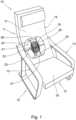
Die Sitzvorrichtung 10 weist eine Fläche 16 zum Aufnehmen, nämlich zum Anlehnen und Sitzen, für eine hier nicht näher dargestellte zu behandelnde Person auf. Hier ist die Fläche 16 beispielhaft mehrteilig ausgebildet und weist eine Rückenlehnfläche 17 und eine Sitzfläche 18 auf. Die Rückenlehnfläche 17 und die Sitzfläche 18 sind in einem vorgegebenen Winkel zueinander angeordnet. Bei diesem Ausführungsbeispiel gehen die Rückenlehnfläche 17 und die Sitzfläche 18 ineinander über. Eine zu behandelnde Person kann sich auf die Sitzfläche 18 setzen und mit seinem Rücken an die Rückenlehnfläche 17 anlehnen.The
Die Sitzvorrichtung 10 weist eine Applikatoreinrichtung 19 auf. Die Applikatoreinrichtung 19 ist zum Erzeugen eines Magnetfeldes für eine Magnetfeldtherapie, hier eine funktionelle Magnetstimulation (FMS), ausgebildet. Hierzu hat die Applikatoreinrichtung 19 eine Spule 20. Bei diesem Ausführungsbeispiel ist die Spule 20 spiralförmig ausgebildet. Mittels der Spule 20 kann unter Ausnutzung des Prinzips der elektromagnetischen Induktion im Körper einer zu behandelnden Person eine Spannung induziert werden, aus der ein Stromfluss resultiert. Erreicht dieser Strom eine ausreichende Stärke, so werden in dem Körper der zu behandelnden Person Muskelzellen und/oder Nervenzellen angeregt bzw. gereizt.The
Die Applikatoreinrichtung 19 ist bei diesem Ausführungsbeispiel in die Rückenlehne 11 der Sitzvorrichtung 10 integriert. Hierbei ist zwischen der Applikatoreinrichtung 19 und einer zu behandelnden Person, die auf der Sitzvorrichtung 10 Platz genommen hat, die Fläche 16 angeordnet.In this embodiment, the
Darüber hinaus weist die Sitzvorrichtung 10 eine Positioniereinrichtung 21 auf. Die Positioniereinrichtung 21 ist zum Verstellen der Applikatoreinrichtung 19 ausgebildet. Die Positioniereinrichtung 21 ist zusammen mit der Applikatoreinrichtung 19 in die Sitzvorrichtung 10, bei diesem Ausführungsbeispiel in die Rückenlehne 11, integriert. Hierbei ist die Applikatoreinrichtung 19 mit der Positioniereinrichtung 21 verbunden.In addition, the
Die Positioniereinrichtung 21 weist bei diesem Ausführungsbeispiel einen Verschiebemechanismus 22 auf. Hierzu hat die Positioniereinrichtung 21 mehrere Schienen 23, 24, 25. Die Schienen 23, 24, 25 sind hier beispielhaft geradlinig und stangenförmig ausgebildet. Die Schiene 23 ist rechtwinklig zu den Schienen 24, 25 ausgerichtet. Die Schienen 24 und 25 sind parallel zueinander angeordnet. Des Weiteren befinden sich alle Schienen 23, 24, 25 im Wesentlichen in derselben Ebene. Die Applikatoreinrichtung 19 ist derart an den Schienen 23, 24, 25 befestigt, dass die Applikatoreinrichtung 19 entlang der Schienen 24, 25 verstellbar ist. Hierbei sind die Schienen 24, 25 im Wesentlichen in Längsrichtung der Sitzvorrichtung 10 bzw. der Rückenlehne 11 ausgerichtet. Somit kann mittels der Positioniereinrichtung 21 eine Höhenverstellung der Applikatoreinrichtung 19 realisiert werden.In this embodiment, the
Die beiden voneinander abgewandten Enden der Schienen 24, 25 weisen jeweils einen Anschlag 26 bzw. 27 auf. Somit ist eine mittels der Schienen 24, 25 realisierte Führungsbahn mittels der Anschläge 26, 27 begrenzt.The two ends of the
Die Schiene 23 ist im Wesentlichen horizontal ausgerichtet. In einer alternativen Ausführungsform kann die Applikatoreinrichtung 19 derart an den Schienen 23, 24, 25 angeordnet sein, dass die Applikatoreinrichtung 19 entlang der Schiene 23 verstellbar ist. Insbesondere kann sowohl eine Verstellbarkeit entlang der Schiene 23 als auch entlang der Schienen 24, 25 gegeben sein. Hierdurch ergibt sich eine besonders flexible Einstellbarkeit der Applikatoreinrichtung 19.The
Mittels der Positioniereinrichtung 21 ist die Applikatoreinrichtung 19 relativ zu der Fläche 16 verstellbar und einstellbar. Hierbei wird die Applikatoreinrichtung 19 bei diesem Ausführungsbeispiel aufgrund einer selbsthemmenden Ausbildung der Positioniereinrichtung 21 in der eingestellten Position gehalten.By means of the
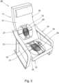
Wenn eine zu behandelnde Person auf dem Sitzelement 12 Platz genommen hat, ist die Fläche 16, hier die Sitzfläche 18, zwischen der Applikatoreinrichtung 19 und der zu behandelnden Person positioniert. Hinsichtlich des Aufbaus und der Funktionsweise der Applikatoreinrichtung 19 und der Positioniereinrichtung 21 wird auch auf die vorangegangene Beschreibung verwiesen.When a person to be treated has taken a seat on the
Die Schienen 24, 25 der Positioniereinrichtung 21 erstrecken sich im Wesentlichen parallel zu den Armlehnen 13, 14. Die Schiene 23 erstreckt sich quer bzw. im Wesentlichen rechtwinklig zwischen den beiden Armlehnen 13, 14. Hierbei ist ein erstes Ende der Schiene 23 in Richtung der Armlehne 13 und ein von dem ersten Ende abgewandtes zweites Ende der Schiene 23 in Richtung der Armlehne 14 gerichtet.The
Somit weist die Sitzvorrichtung 29 eine erste Applikatoreinrichtung 19 und eine erste Positioniereinrichtung 21 in der Rückenlehne 11 auf. Zusätzlich weist die Sitzvorrichtung 29 eine zweite Applikatoreinrichtung 19 und eine zweite Positioniereinrichtung 21 in dem Sitzelement 12 auf. Hinsichtlich der Funktion und des Aufbaus der Applikatoreinrichtung 19 bzw. der Positioniereinrichtung 21 wird auch auf die vorangegangene Beschreibung verwiesen.Thus, the
Aufgrund der Kombination von zwei Applikatoreinrichtungen 19 gemäß der Sitzvorrichtung 29 können die beiden mittels der jeweiligen Spule 20 erzeugbaren Magnetfelder überlagert werden. Hierbei kann die Überlagerung der Magnetfelder mittels der beiden Positioniereinrichtungen 21 individuell auf die zu behandelnde Körperregion einer zu behandelnden Person eingestellt werden.Due to the combination of two
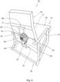
Anstelle der Applikatoreinrichtung 19 gemäß
Im Vergleich zu der Applikatoreinrichtung 19 weist die Applikatoreinrichtung 35 zusätzlich eine Kühleinrichtung 33 auf. Die Kühleinrichtung 33 wird anhand der folgenden Figur näher erläutert.In comparison to the
Die Applikatoreinrichtung 35 weist ein Gehäuse 30 auf. Innerhalb des Gehäuses 30 ist die Spule 20 angeordnet. Die Spule 20 ist aus einer Leitung 31 gebildet. Die Leitung 31 ist durch eine geeignete Öffnung 32 aus dem Gehäuse 30 herausgeführt. Des Weiteren ist die Leitung 31 mit einer hier nicht näher dargestellten Energiequelle verbunden.The
Das Gehäuse 30 ist verschiebbar bzw. verstellbar mit der Positioniereinrichtung 21 verbunden Die Applikatoreinrichtung 35 kann manuell oder mittels eines hier nicht näher dargestellten Antriebs, insbesondere eines elektrischen Antriebes, mittels der Positioniereinrichtung 21 verstellt werden. Bei diesem Ausführungsbeispiel ist das Gehäuse 30 entlang der Schienen 23, 24, 25 verschiebbar. Hierbei ist das Gehäuse 30 selbsthemmend an den Schienen 23, 24, 25 gehalten. In einer alternativen Ausführungsform kann eine Halteeinrichtung vorhanden sein, die zum Halten der Applikatoreinrichtung 35 in der gewünschten Position ausgebildet ist.The
Die Applikatoreinrichtung 35 weist eine Kühleinrichtung 33 auf. Hier ist die Kühleinrichtung 33 an dem Gehäuse 30 befestigt, nämlich an einer von der Fläche 16, beispielsweise der Rückenlehnfläche 17 oder der Sitzfläche 18, abgewandten Seite des Gehäuses 30. Die Kühleinrichtung 33 weist bei diesem Ausführungsbeispiel einen Ventilator 36 auf, um Luft als Kühlmittel durch das Gehäuse 30 und über die Spule 20 zu fördern.The
Das Gehäuse 30 hat mehrere Öffnungen 37, um eine Luftzirkulation zu ermöglichen. Für eine bessere Übersichtlichkeit sind nicht alle Öffnungen 37 mit einem Bezugszeichen versehen. Bei diesem Ausführungsbeispiel ist die Kühleinrichtung 33 derart ausgebildet, dass Luft mittels des Ventilators 36 durch die Applikatoreinrichtung 35 gesaugt wird. Hierbei wird Luft durch die Öffnungen 37 in das Innere des Gehäuses 30 und über die Spule in Richtung des Ventilators 36 gefördert. Bei diesem Ausführungsbeispiel sind die Öffnungen 37 radial um den Außenumfang des Gehäuses 30 verteilt angeordnet. Zum Abführen der angesaugten Luft weist die Kühleinrichtung 33 mindestens eine Öffnung 38 auf.The
In einer alternativen Ausführungsform kann die Luft mittels der Kühleinrichtung 33 bzw. dem Ventilator 36 durch die Applikatoreinrichtung 35 bzw. das Gehäuse 30 geblasen werden. Hierbei wird die Luft mittels des Ventilators 36 von der mindestens einen Öffnung 38 in Richtung der Öffnungen 37 gefördert.In an alternative embodiment, the air can be blown through the
In einer weiteren alternativen Ausführungsform kann anstellen von Luft eine Flüssigkeit als Kühlmittel eingesetzt werden. Hierzu kann die Kühleinrichtung 33 anstelle eines Ventilators 36 eine Pumpe aufweisen, die die Flüssigkeit mittels einer oder mehrerer Leitung in das Gehäuse 30 und/oder zu der Spule 20 führt.In a further alternative embodiment, a liquid can be used as a coolant instead of air. For this purpose, the
Bezugszeichenliste:List of reference symbols:
- 1010
- SitzvorrichtungSeating device
- 1111
- Rückenlehnebackrest
- 1212
- SitzelementSeat element
- 1313
- Armlehnearmrest
- 1414
- Armlehnearmrest
- 1515
- TragstrukturSupporting structure
- 1616
- FlächeArea
- 1717
- RückenlehnflächeBackrest
- 1818
- SitzflächeSeat
- 1919
- ApplikatoreinrichtungApplicator device
- 2020
- SpuleKitchen sink
- 2121
- PositioniereinrichtungPositioning device
- 2222
- VerschiebemechanismusShifting mechanism
- 2323
- Schienerail
- 2424
- Schienerail
- 2525
- Schienerail
- 2626
- Anschlagattack
- 2727
- Anschlagattack
- 2828
- SitzvorrichtungSeating device
- 2929
- SitzvorrichtungSeating device
- 3030
- GehäuseHousing
- 3131
- LeitungLine
- 3232
- Öffnungopening
- 3333
- KühleinrichtungCooling device
- 3434
- SitzvorrichtungSeating device
- 3535
- ApplikatoreinrichtungApplicator device
- 3636
- Ventilatorfan
- 3737
- Öffnungopening
Claims (10)
Translated fromGermanPriority Applications (1)
| Application Number | Priority Date | Filing Date | Title |
|---|---|---|---|
| DE102016116399.6ADE102016116399B4 (en) | 2016-09-01 | 2016-09-01 | Sitting or lying device for magnetic field therapy |
Applications Claiming Priority (1)
| Application Number | Priority Date | Filing Date | Title |
|---|---|---|---|
| DE102016116399.6ADE102016116399B4 (en) | 2016-09-01 | 2016-09-01 | Sitting or lying device for magnetic field therapy |
Publications (2)
| Publication Number | Publication Date |
|---|---|
| DE102016116399A1 DE102016116399A1 (en) | 2018-03-01 |
| DE102016116399B4true DE102016116399B4 (en) | 2024-06-27 |
Family
ID=61167062
Family Applications (1)
| Application Number | Title | Priority Date | Filing Date |
|---|---|---|---|
| DE102016116399.6AActiveDE102016116399B4 (en) | 2016-09-01 | 2016-09-01 | Sitting or lying device for magnetic field therapy |
Country Status (1)
| Country | Link |
|---|---|
| DE (1) | DE102016116399B4 (en) |
Families Citing this family (23)
| Publication number | Priority date | Publication date | Assignee | Title |
|---|---|---|---|---|
| DE102012013534B3 (en) | 2012-07-05 | 2013-09-19 | Tobias Sokolowski | Apparatus for repetitive nerve stimulation for the degradation of adipose tissue by means of inductive magnetic fields |
| US11491342B2 (en) | 2015-07-01 | 2022-11-08 | Btl Medical Solutions A.S. | Magnetic stimulation methods and devices for therapeutic treatments |
| US11266850B2 (en) | 2015-07-01 | 2022-03-08 | Btl Healthcare Technologies A.S. | High power time varying magnetic field therapy |
| US10695575B1 (en) | 2016-05-10 | 2020-06-30 | Btl Medical Technologies S.R.O. | Aesthetic method of biological structure treatment by magnetic field |
| US20180001107A1 (en) | 2016-07-01 | 2018-01-04 | Btl Holdings Limited | Aesthetic method of biological structure treatment by magnetic field |
| US11253717B2 (en) | 2015-10-29 | 2022-02-22 | Btl Healthcare Technologies A.S. | Aesthetic method of biological structure treatment by magnetic field |
| US11464993B2 (en) | 2016-05-03 | 2022-10-11 | Btl Healthcare Technologies A.S. | Device including RF source of energy and vacuum system |
| US11247039B2 (en) | 2016-05-03 | 2022-02-15 | Btl Healthcare Technologies A.S. | Device including RF source of energy and vacuum system |
| US11534619B2 (en) | 2016-05-10 | 2022-12-27 | Btl Medical Solutions A.S. | Aesthetic method of biological structure treatment by magnetic field |
| US10583287B2 (en) | 2016-05-23 | 2020-03-10 | Btl Medical Technologies S.R.O. | Systems and methods for tissue treatment |
| US10556122B1 (en) | 2016-07-01 | 2020-02-11 | Btl Medical Technologies S.R.O. | Aesthetic method of biological structure treatment by magnetic field |
| US11141219B1 (en) | 2016-08-16 | 2021-10-12 | BTL Healthcare Technologies, a.s. | Self-operating belt |
| DE102017125678A1 (en)* | 2017-11-03 | 2019-05-09 | Prof. Dr. Fischer AG | Magnetic field applicator for magnetic field treatment of persons on a treatment couch and / or a treatment chair |
| DE202018106565U1 (en)* | 2018-11-20 | 2019-10-11 | Prof. Dr. Fischer AG | Treatment chair for the magnetic stimulation of body tissue |
| ES2926904T3 (en) | 2019-04-11 | 2022-10-31 | Btl Medical Solutions A S | Device for the aesthetic treatment of biological structures using radiofrequency and magnetic energy |
| US12156689B2 (en) | 2019-04-11 | 2024-12-03 | Btl Medical Solutions A.S. | Methods and devices for aesthetic treatment of biological structures by radiofrequency and magnetic energy |
| WO2021224678A1 (en) | 2020-05-04 | 2021-11-11 | Btl Medical Technologies S.R.O. | Device and method for unattended treatment of a patient |
| US11878167B2 (en) | 2020-05-04 | 2024-01-23 | Btl Healthcare Technologies A.S. | Device and method for unattended treatment of a patient |
| EP4415812A1 (en) | 2021-10-13 | 2024-08-21 | BTL Medical Solutions a.s. | Devices for aesthetic treatment of biological structures by radiofrequency and magnetic energy |
| US11896816B2 (en) | 2021-11-03 | 2024-02-13 | Btl Healthcare Technologies A.S. | Device and method for unattended treatment of a patient |
| EP4467188A1 (en)* | 2023-05-23 | 2024-11-27 | Iskra Medical d.o.o. | Magnetic-field applicator for feet |
| DE102023114830B4 (en) | 2023-06-06 | 2025-02-27 | Bayerische Motoren Werke Aktiengesellschaft | Control unit for the independent control of applicator devices for generating a magnetic field for functional magnetic stimulation of an occupant, as well as seat system and vehicle |
| DE102023131641A1 (en)* | 2023-11-14 | 2025-05-15 | Bayerische Motoren Werke Aktiengesellschaft | Sports equipment with integrated muscle stimulation system and method for controlling |
Citations (8)
| Publication number | Priority date | Publication date | Assignee | Title |
|---|---|---|---|---|
| GB429044A (en) | 1933-12-16 | 1935-05-23 | Suzanne Sara Stokvis Simpson | Improvements in and relating to electromagnetic therapeutic apparatus |
| WO1991015263A1 (en)* | 1990-04-02 | 1991-10-17 | Holcomb Medical Corporation | Electromagnetic treatment device |
| US5453074A (en)* | 1992-06-01 | 1995-09-26 | Yuugenkaisha World Nikken | Electromagnetic therapy apparatus |
| US5984854A (en) | 1996-02-15 | 1999-11-16 | Nihon Kohden Corporation | Method for treating urinary incontinence and an apparatus therefor |
| US6213933B1 (en)* | 1998-09-10 | 2001-04-10 | Vernon Wen-Hau Lin | Apparatus and method for functional magnetic stimulation |
| DE102004006192A1 (en)* | 2004-02-06 | 2005-09-15 | Axel Muntermann | Device for treatment with magnetic fields |
| WO2012123584A1 (en)* | 2011-03-17 | 2012-09-20 | Magic Race Llc | Device for extracorporeal magnetic innervation |
| DE102012012149A1 (en) | 2012-06-20 | 2013-12-24 | Quantenmedicine AG | Method and device for machine-assisted pelvic floor training |
- 2016
- 2016-09-01DEDE102016116399.6Apatent/DE102016116399B4/enactiveActive
Patent Citations (8)
| Publication number | Priority date | Publication date | Assignee | Title |
|---|---|---|---|---|
| GB429044A (en) | 1933-12-16 | 1935-05-23 | Suzanne Sara Stokvis Simpson | Improvements in and relating to electromagnetic therapeutic apparatus |
| WO1991015263A1 (en)* | 1990-04-02 | 1991-10-17 | Holcomb Medical Corporation | Electromagnetic treatment device |
| US5453074A (en)* | 1992-06-01 | 1995-09-26 | Yuugenkaisha World Nikken | Electromagnetic therapy apparatus |
| US5984854A (en) | 1996-02-15 | 1999-11-16 | Nihon Kohden Corporation | Method for treating urinary incontinence and an apparatus therefor |
| US6213933B1 (en)* | 1998-09-10 | 2001-04-10 | Vernon Wen-Hau Lin | Apparatus and method for functional magnetic stimulation |
| DE102004006192A1 (en)* | 2004-02-06 | 2005-09-15 | Axel Muntermann | Device for treatment with magnetic fields |
| WO2012123584A1 (en)* | 2011-03-17 | 2012-09-20 | Magic Race Llc | Device for extracorporeal magnetic innervation |
| DE102012012149A1 (en) | 2012-06-20 | 2013-12-24 | Quantenmedicine AG | Method and device for machine-assisted pelvic floor training |
Also Published As
| Publication number | Publication date |
|---|---|
| DE102016116399A1 (en) | 2018-03-01 |
Similar Documents
| Publication | Publication Date | Title |
|---|---|---|
| DE102016116399B4 (en) | Sitting or lying device for magnetic field therapy | |
| DE102012013534B3 (en) | Apparatus for repetitive nerve stimulation for the degradation of adipose tissue by means of inductive magnetic fields | |
| EP3355987B1 (en) | Magnetic stimulation device | |
| DE102004006192B4 (en) | Device for treatment with magnetic fields | |
| EP3243495B1 (en) | Device for the temporary stretching and relieving of the spine of a human being | |
| WO2009156117A2 (en) | Apparatus for magnetic field therapy | |
| EP3373773A1 (en) | Portable headrest for body positions lying on the stomach, for self-application and as an therapeutic aid | |
| EP0084093A1 (en) | Reclining chair for patients | |
| DE102017219101A1 (en) | Device for therapy and diagnostics in the retroperitoneum, in the lumbar and in the lower lung and / or pleural area of a patient | |
| EP2515999A1 (en) | Treatment device using magnetic fields | |
| EP1363701B1 (en) | Treatment device with treatment bed and treatment apparatus | |
| DE102008051223A1 (en) | Device for seating, particularly therapy chair, has seat surface and pelvis part for laying back part of human pelvis, and rear part for laying back at back of body | |
| DE102011116524A1 (en) | Device for storing a patient | |
| DE202018106092U1 (en) | Bath tub | |
| DE102014207568A1 (en) | X-ray device | |
| EP2086489A1 (en) | Dental treatment chair | |
| DE102013003746B4 (en) | Chair, strength training device and use of a chair as a strength training device | |
| DE1491140A1 (en) | Trunk support device for patients with poor posture | |
| DE102018104515B4 (en) | Device for transcranial magnetic stimulation | |
| DE29808990U1 (en) | Seating and reclining furniture for magnetic field therapy | |
| DE10297419T5 (en) | Seat frame for use with an extracorporeal treatment device with high intensity focused ultrasonic wave | |
| AT520259B1 (en) | Therapy couch | |
| DE102010011839B4 (en) | Sports and / or therapy facility | |
| DE965438C (en) | Radiation chair for the treatment of the human body | |
| AT514418A1 (en) | Device for back treatment |
Legal Events
| Date | Code | Title | Description |
|---|---|---|---|
| R012 | Request for examination validly filed | ||
| R079 | Amendment of ipc main class | Free format text:PREVIOUS MAIN CLASS: A61N0002000000 Ipc:A61N0002040000 | |
| R016 | Response to examination communication | ||
| R082 | Change of representative | Representative=s name:TAPPE, UDO, DIPL.-PHYS. DR.RER.NAT., DE | |
| R016 | Response to examination communication | ||
| R016 | Response to examination communication | ||
| R018 | Grant decision by examination section/examining division | ||
| R020 | Patent grant now final |