DE102016109601A1 - Arrangement for the sterile handling of non-sterile units in a sterile environment - Google Patents
Arrangement for the sterile handling of non-sterile units in a sterile environmentDownload PDFInfo
- Publication number
- DE102016109601A1 DE102016109601A1DE102016109601.6ADE102016109601ADE102016109601A1DE 102016109601 A1DE102016109601 A1DE 102016109601A1DE 102016109601 ADE102016109601 ADE 102016109601ADE 102016109601 A1DE102016109601 A1DE 102016109601A1
- Authority
- DE
- Germany
- Prior art keywords
- sterile
- connector
- endoscope
- cable
- lock
- Prior art date
- Legal status (The legal status is an assumption and is not a legal conclusion. Google has not performed a legal analysis and makes no representation as to the accuracy of the status listed.)
- Withdrawn
Links
- 230000000295complement effectEffects0.000claimsabstractdescription19
- 230000008878couplingEffects0.000claimsabstractdescription12
- 238000010168coupling processMethods0.000claimsabstractdescription12
- 238000005859coupling reactionMethods0.000claimsabstractdescription12
- 230000003287optical effectEffects0.000claimsdescription80
- 238000001356surgical procedureMethods0.000claimsdescription13
- 239000013307optical fiberSubstances0.000claimsdescription5
- 239000004020conductorSubstances0.000claimsdescription4
- 238000000034methodMethods0.000claimsdescription4
- 238000000926separation methodMethods0.000claimsdescription4
- 230000005540biological transmissionEffects0.000description22
- 238000005286illuminationMethods0.000description8
- 238000012545processingMethods0.000description6
- 238000003780insertionMethods0.000description4
- 230000037431insertionEffects0.000description4
- 238000002432robotic surgeryMethods0.000description4
- 238000011109contaminationMethods0.000description3
- 238000013461designMethods0.000description3
- 238000011161developmentMethods0.000description3
- 230000018109developmental processEffects0.000description3
- 238000001839endoscopyMethods0.000description2
- 210000003746featherAnatomy0.000description2
- 238000004519manufacturing processMethods0.000description2
- 238000007789sealingMethods0.000description2
- BUHVIAUBTBOHAG-FOYDDCNASA-N(2r,3r,4s,5r)-2-[6-[[2-(3,5-dimethoxyphenyl)-2-(2-methylphenyl)ethyl]amino]purin-9-yl]-5-(hydroxymethyl)oxolane-3,4-diolChemical compoundCOC1=CC(OC)=CC(C(CNC=2C=3N=CN(C=3N=CN=2)[C@H]2[C@@H]([C@H](O)[C@@H](CO)O2)O)C=2C(=CC=CC=2)C)=C1BUHVIAUBTBOHAG-FOYDDCNASA-N0.000description1
- 210000003484anatomyAnatomy0.000description1
- 238000005266castingMethods0.000description1
- 230000008859changeEffects0.000description1
- 238000005520cutting processMethods0.000description1
- 230000007547defectEffects0.000description1
- 230000001419dependent effectEffects0.000description1
- 230000001066destructive effectEffects0.000description1
- 238000007688edgingMethods0.000description1
- 239000012636effectorSubstances0.000description1
- 238000011156evaluationMethods0.000description1
- 239000000835fiberSubstances0.000description1
- 238000003384imaging methodMethods0.000description1
- 230000036512infertilityEffects0.000description1
- 239000000463materialSubstances0.000description1
- 229920000642polymerPolymers0.000description1
- 238000003825pressingMethods0.000description1
- 230000008569processEffects0.000description1
- 230000001681protective effectEffects0.000description1
- 238000001454recorded imageMethods0.000description1
- 125000006850spacer groupChemical group0.000description1
- 238000001228spectrumMethods0.000description1
- 230000001954sterilising effectEffects0.000description1
- 238000004659sterilization and disinfectionMethods0.000description1
- 238000003860storageMethods0.000description1
Images


Classifications
- A—HUMAN NECESSITIES
- A61—MEDICAL OR VETERINARY SCIENCE; HYGIENE
- A61B—DIAGNOSIS; SURGERY; IDENTIFICATION
- A61B1/00—Instruments for performing medical examinations of the interior of cavities or tubes of the body by visual or photographical inspection, e.g. endoscopes; Illuminating arrangements therefor
- A61B1/00112—Connection or coupling means
- A61B1/00114—Electrical cables in or with an endoscope
- A—HUMAN NECESSITIES
- A61—MEDICAL OR VETERINARY SCIENCE; HYGIENE
- A61B—DIAGNOSIS; SURGERY; IDENTIFICATION
- A61B1/00—Instruments for performing medical examinations of the interior of cavities or tubes of the body by visual or photographical inspection, e.g. endoscopes; Illuminating arrangements therefor
- A61B1/00142—Instruments for performing medical examinations of the interior of cavities or tubes of the body by visual or photographical inspection, e.g. endoscopes; Illuminating arrangements therefor with means for preventing contamination, e.g. by using a sanitary sheath
- A—HUMAN NECESSITIES
- A61—MEDICAL OR VETERINARY SCIENCE; HYGIENE
- A61B—DIAGNOSIS; SURGERY; IDENTIFICATION
- A61B1/00—Instruments for performing medical examinations of the interior of cavities or tubes of the body by visual or photographical inspection, e.g. endoscopes; Illuminating arrangements therefor
- A61B1/00112—Connection or coupling means
- A61B1/00117—Optical cables in or with an endoscope
- A—HUMAN NECESSITIES
- A61—MEDICAL OR VETERINARY SCIENCE; HYGIENE
- A61B—DIAGNOSIS; SURGERY; IDENTIFICATION
- A61B1/00—Instruments for performing medical examinations of the interior of cavities or tubes of the body by visual or photographical inspection, e.g. endoscopes; Illuminating arrangements therefor
- A61B1/00112—Connection or coupling means
- A61B1/00121—Connectors, fasteners and adapters, e.g. on the endoscope handle
- A—HUMAN NECESSITIES
- A61—MEDICAL OR VETERINARY SCIENCE; HYGIENE
- A61B—DIAGNOSIS; SURGERY; IDENTIFICATION
- A61B1/00—Instruments for performing medical examinations of the interior of cavities or tubes of the body by visual or photographical inspection, e.g. endoscopes; Illuminating arrangements therefor
- A61B1/06—Instruments for performing medical examinations of the interior of cavities or tubes of the body by visual or photographical inspection, e.g. endoscopes; Illuminating arrangements therefor with illuminating arrangements
- A61B1/07—Instruments for performing medical examinations of the interior of cavities or tubes of the body by visual or photographical inspection, e.g. endoscopes; Illuminating arrangements therefor with illuminating arrangements using light-conductive means, e.g. optical fibres
- A—HUMAN NECESSITIES
- A61—MEDICAL OR VETERINARY SCIENCE; HYGIENE
- A61B—DIAGNOSIS; SURGERY; IDENTIFICATION
- A61B34/00—Computer-aided surgery; Manipulators or robots specially adapted for use in surgery
- A61B34/30—Surgical robots
- A61B34/35—Surgical robots for telesurgery
- A—HUMAN NECESSITIES
- A61—MEDICAL OR VETERINARY SCIENCE; HYGIENE
- A61B—DIAGNOSIS; SURGERY; IDENTIFICATION
- A61B34/00—Computer-aided surgery; Manipulators or robots specially adapted for use in surgery
- A61B34/70—Manipulators specially adapted for use in surgery
- A61B34/74—Manipulators with manual electric input means
- A—HUMAN NECESSITIES
- A61—MEDICAL OR VETERINARY SCIENCE; HYGIENE
- A61B—DIAGNOSIS; SURGERY; IDENTIFICATION
- A61B46/00—Surgical drapes
- A61B46/10—Surgical drapes specially adapted for instruments, e.g. microscopes
- A—HUMAN NECESSITIES
- A61—MEDICAL OR VETERINARY SCIENCE; HYGIENE
- A61B—DIAGNOSIS; SURGERY; IDENTIFICATION
- A61B17/00—Surgical instruments, devices or methods
- A61B2017/00477—Coupling
- A—HUMAN NECESSITIES
- A61—MEDICAL OR VETERINARY SCIENCE; HYGIENE
- A61B—DIAGNOSIS; SURGERY; IDENTIFICATION
- A61B34/00—Computer-aided surgery; Manipulators or robots specially adapted for use in surgery
- A61B34/30—Surgical robots
- A61B2034/301—Surgical robots for introducing or steering flexible instruments inserted into the body, e.g. catheters or endoscopes
- A—HUMAN NECESSITIES
- A61—MEDICAL OR VETERINARY SCIENCE; HYGIENE
- A61B—DIAGNOSIS; SURGERY; IDENTIFICATION
- A61B90/00—Instruments, implements or accessories specially adapted for surgery or diagnosis and not covered by any of the groups A61B1/00 - A61B50/00, e.g. for luxation treatment or for protecting wound edges
- A61B90/08—Accessories or related features not otherwise provided for
- A61B2090/0813—Accessories designed for easy sterilising, i.e. re-usable
- H—ELECTRICITY
- H01—ELECTRIC ELEMENTS
- H01R—ELECTRICALLY-CONDUCTIVE CONNECTIONS; STRUCTURAL ASSOCIATIONS OF A PLURALITY OF MUTUALLY-INSULATED ELECTRICAL CONNECTING ELEMENTS; COUPLING DEVICES; CURRENT COLLECTORS
- H01R13/00—Details of coupling devices of the kinds covered by groups H01R12/70 or H01R24/00 - H01R33/00
- H01R13/44—Means for preventing access to live contacts
- H01R13/447—Shutter or cover plate
- H01R13/453—Shutter or cover plate opened by engagement of counterpart
- H01R13/4536—Inwardly pivoting shutter
- H—ELECTRICITY
- H01—ELECTRIC ELEMENTS
- H01R—ELECTRICALLY-CONDUCTIVE CONNECTIONS; STRUCTURAL ASSOCIATIONS OF A PLURALITY OF MUTUALLY-INSULATED ELECTRICAL CONNECTING ELEMENTS; COUPLING DEVICES; CURRENT COLLECTORS
- H01R13/00—Details of coupling devices of the kinds covered by groups H01R12/70 or H01R24/00 - H01R33/00
- H01R13/44—Means for preventing access to live contacts
- H01R13/447—Shutter or cover plate
- H01R13/453—Shutter or cover plate opened by engagement of counterpart
- H01R13/4538—Covers sliding or withdrawing in the direction of engagement
- H—ELECTRICITY
- H01—ELECTRIC ELEMENTS
- H01R—ELECTRICALLY-CONDUCTIVE CONNECTIONS; STRUCTURAL ASSOCIATIONS OF A PLURALITY OF MUTUALLY-INSULATED ELECTRICAL CONNECTING ELEMENTS; COUPLING DEVICES; CURRENT COLLECTORS
- H01R13/00—Details of coupling devices of the kinds covered by groups H01R12/70 or H01R24/00 - H01R33/00
- H01R13/46—Bases; Cases
- H01R13/52—Dustproof, splashproof, drip-proof, waterproof, or flameproof cases
- H01R13/5213—Covers
- H—ELECTRICITY
- H01—ELECTRIC ELEMENTS
- H01R—ELECTRICALLY-CONDUCTIVE CONNECTIONS; STRUCTURAL ASSOCIATIONS OF A PLURALITY OF MUTUALLY-INSULATED ELECTRICAL CONNECTING ELEMENTS; COUPLING DEVICES; CURRENT COLLECTORS
- H01R13/00—Details of coupling devices of the kinds covered by groups H01R12/70 or H01R24/00 - H01R33/00
- H01R13/46—Bases; Cases
- H01R13/52—Dustproof, splashproof, drip-proof, waterproof, or flameproof cases
- H01R13/5224—Dustproof, splashproof, drip-proof, waterproof, or flameproof cases for medical use
- H—ELECTRICITY
- H01—ELECTRIC ELEMENTS
- H01R—ELECTRICALLY-CONDUCTIVE CONNECTIONS; STRUCTURAL ASSOCIATIONS OF A PLURALITY OF MUTUALLY-INSULATED ELECTRICAL CONNECTING ELEMENTS; COUPLING DEVICES; CURRENT COLLECTORS
- H01R2201/00—Connectors or connections adapted for particular applications
- H01R2201/12—Connectors or connections adapted for particular applications for medicine and surgery
Landscapes
- Health & Medical Sciences (AREA)
- Life Sciences & Earth Sciences (AREA)
- Surgery (AREA)
- Engineering & Computer Science (AREA)
- General Health & Medical Sciences (AREA)
- Veterinary Medicine (AREA)
- Public Health (AREA)
- Animal Behavior & Ethology (AREA)
- Molecular Biology (AREA)
- Medical Informatics (AREA)
- Biomedical Technology (AREA)
- Heart & Thoracic Surgery (AREA)
- Nuclear Medicine, Radiotherapy & Molecular Imaging (AREA)
- Biophysics (AREA)
- Radiology & Medical Imaging (AREA)
- Physics & Mathematics (AREA)
- Pathology (AREA)
- Optics & Photonics (AREA)
- Robotics (AREA)
- Endoscopes (AREA)
- Accommodation For Nursing Or Treatment Tables (AREA)
Abstract
Translated fromGermanDescription
Translated fromGermanDie Erfindung betrifft eine erste Anordnung zur sterilen Handhabung eines nicht sterilen Endoskops in einer sterilen Umgebung. Die Anordnung umfasst eine sterile Endoskophülle zur Aufnahme des Endoskops, ein Kabel, über das das Endoskop mit einer Steuereinheit verbindbar ist und eine sterile Kabelhülle zur Aufnahme zumindest eines Abschnitts des Kabels. Ferner betrifft die Erfindung eine zweite Anordnung zum Herstellen und Lösen einer Steckverbindung zwischen einem ersten nicht sterilen Steckverbinder und einem zum ersten Steckverbinder komplementären zweiten nicht sterilen Steckverbinder in einer sterilen Umgebung. Diese zweite Anordnung umfasst eine erste sterile Hülle zur Aufnahme zumindest des ersten Steckverbinders und eine zweite sterile Hülle zur Aufnahme zumindest des zweiten Steckverbinders.The invention relates to a first arrangement for the sterile handling of a non-sterile endoscope in a sterile environment. The assembly includes a sterile endoscope cover for receiving the endoscope, a cable via which the endoscope is connectable to a control unit, and a sterile cable sheath for receiving at least a portion of the cable. Furthermore, the invention relates to a second arrangement for making and releasing a connector between a first non-sterile connector and a first connector complementary second non-sterile connector in a sterile environment. This second arrangement comprises a first sterile sheath for receiving at least the first connector and a second sterile sheath for receiving at least the second connector.
Der Erfindung liegt die Idee zugrunde, ein nicht steriles Endoskop in einem sterilen Umfeld, wie einem Operationssaal, zu verwenden, ohne das Endoskop sterilisieren zu müssen. Grundsätzlich wäre es zwar auch möglich, sterile Einmalendoskope zu verwenden, die nur für eine einzige Operation genutzt werden, jedoch ist dies weder aus ökonomischer Sicht noch aus Sicht des schonenden Umgangs mit Ressourcen sinnvoll. Zusammen mit dem Endoskop sollten auch Verbindungskabel zwischen einer Steuereinheit und dem Endoskop bei Mehrfachverwendung nicht vor jeder Verwendung sterilisiert werden müssen. Zur Verwendung von nicht sterilen Endoskopen in einem sterilen Umfeld ist aus dem Dokument
Aus dem Dokument
Aus dem Dokument
Nachteilig an diesen bekannten Lösungen ist, dass das Endoskop im sterilen Bereich nicht von dem Verbindungskabel trennbar und gegen ein anderes Endoskop austauschbar ist, ohne die Sterilität im sterilen Umfeld zu gefährden. Damit ist in der Praxis kein Wechseln des Endoskops im sterilen Bereich während einer Operation möglich. Sollte ein Endoskop während einer Operation einen Defekt aufweisen und ersetzt werden müssen, oder sollte während einer Operation ein eingesetztes Endoskop gegen ein weiteres Endoskop mit anderen optischen und/oder geometrischen Eigenschaften ausgetauscht werden, so müsste dieses zweite Endoskop zusammen mit einem sterilen Kabel bereits vor der Operation steril verpackt werden und dann während der Operation gegen das zweite steril verpackte Endoskop ausgetauscht werden. Alternativ können sterile Endoskope und/oder sterile Kabel auch im sterilen Umfeld gegeneinander ausgetauscht werden. Jedoch ist es sehr aufwändig, Endoskope und Kabel vor jeder Verwendung zu sterilisieren. Hierzu ist es erforderlich, dass das Endoskop nach jeder Verwendung gereinigt und autoklaviert wird. Im Autoklaven ist das Endoskop Wasserdampf bei einer Temperatur von ca. 140°C und einem Druck von mehreren bar ausgesetzt, so dass an das Endoskop erhebliche thermische und mechanische Anforderungen gestellt werden müssen, damit dieses den Sterilisationsprozess im Autoklaven sicher übersteht.A disadvantage of these known solutions is that the endoscope in the sterile field is not separable from the connection cable and exchangeable with another endoscope, without endangering the sterility in the sterile environment. Thus, in practice no changing of the endoscope in the sterile field during surgery is possible. Should an endoscope have a defect during surgery and need to be replaced, or should an inserted endoscope be exchanged for another endoscope with different optical and / or geometrical properties during surgery, then this second endoscope, together with a sterile cable, would have to be replaced before Be packaged sterile and then replaced during surgery against the second sterile packed endoscope. Alternatively, sterile endoscopes and / or sterile cables can also be exchanged for one another in a sterile environment. However, it is very expensive to sterilize endoscopes and cables before each use. For this, it is necessary that the endoscope is cleaned and autoclaved after each use. In the autoclave, the endoscope is exposed to steam at a temperature of about 140 ° C and a pressure of several bar, so that the endoscope considerable thermal and mechanical requirements must be made so that it survives the sterilization process in the autoclave.
Ähnliche Probleme treten bei der Verbindung mehrerer Steckverbinder auf, die entweder direkt an steril verpackten Geräten und/oder an Kabelenden vorgesehen sind.Similar problems arise in the connection of multiple connectors, which are provided either directly to sterile packaged devices and / or cable ends.
Aufgabe der Erfindung ist es, eine Anordnung zur sterilen Handhabung eines nicht sterilen Endoskops in einer sterilen Umgebung sowie eine Anordnung zum Herstellen und Lösen einer Steckverbindung zwischen einem ersten nicht sterilen Steckverbinder und einem zweiten nicht sterilen Steckverbinder in einer sterilen Umgebung anzugeben, die das Herstellen und Trennen einer Verbindung zwischen dem Endoskop und einem Kabel bzw. zwischen zwei Steckverbindern ermöglichen, ohne die sterile Umgebung zu kontaminieren. Darüber hinaus ist ein System zur robotergestützten Chirurgie, insbesondere zu einer telerobotergestützten Prozedur innerhalb eines sterilen Bereichs anzugeben, bei der das Endoskop im sterilen Bereich mit Hilfe eines Manipulatorarms eines Manipulators positionierbar ist.The object of the invention is to provide an arrangement for sterile handling of a non-sterile endoscope in a sterile environment and an arrangement for making and releasing a connector between a first non-sterile connector and a second non-sterile connector in a sterile environment, the manufacture and Disconnect between the endoscope and a cable, or between two connectors, without contaminating the sterile environment. In addition, a robot-assisted surgery system, in particular a telerobot-assisted procedure within a sterile area, in which the endoscope can be positioned in the sterile area by means of a manipulator arm of a manipulator must be provided.
Diese Aufgabe wird durch eine Anordnung zur sterilen Handhabung eines nicht sterilen Endoskops in einer sterilen Umgebung mit den Merkmalen des Anspruchs 1, durch eine Anordnung zur robotergestützten Chirurgie mit den Merkmalen des Anspruchs 14 sowie durch eine Anordnung zum Herstellen und Lösen einer Steckverbindung zwischen einem ersten sterilen Steckverbinder und einem zweiten sterilen Steckverbinder in einer sterilen Umgebung mit den Merkmalen des Anspruchs 15 gelöst. Vorteilhafte Weiterbildungen sind in den abhängigen Ansprüchen angegeben.This object is achieved by an arrangement for sterile handling of a non-sterile endoscope in a sterile environment with the features of claim 1, by a robot-assisted surgery arrangement with the features of
Durch eine Anordnung zur sterilen Handhabung eines nicht sterilen Endoskops in einer sterilen Umgebung mit den Merkmalen des Anspruchs 1 wird erreicht, dass eine direkte Verbindung zwischen dem nicht sterilen Endoskop und mit dem nicht sterilen Kabel bzw. mit dem nicht sterilen mit dem Kabel verbundenen Steckverbinder sowohl sicher herstellbar als auch trennbar ist, ohne dass die Gefahr besteht, dass der sterile Bereich kontaminiert werden kann. Dies wird insbesondere durch die erste Sterilschleuse mit der ersten Sterilklappe und die zweite Sterilschleuse mit der zweiten Sterilklappe erreicht. Dadurch ist sowohl ein einfacher Austausch eines Endoskops gegen ein weiteres Endoskop im sterilen Umfeld als auch das Wiederverbinden eines bereits zuvor im sterilen Umfeld mit dem Kabel verbundenen Endoskops möglich. Dies ist insbesondere dann sinnvoll, wenn mehrere Endoskope mit unterschiedlichen optischen und/oder geometrischen Eigenschaften bei einer medizinischen Behandlung, insbesondere einer Operation, eingesetzt werden.An arrangement for the sterile handling of a non-sterile endoscope in a sterile environment with the features of claim 1 ensures that a direct connection between the non-sterile endoscope and with the non-sterile cable or with the non-sterile connected to the cable connector both is safe to produce and separable, without the risk that the sterile area can be contaminated. This is achieved in particular by the first sterile lock with the first sterile flap and the second sterile lock with the second sterile flap. As a result, both a simple exchange of an endoscope against another endoscope in a sterile environment as well as the reconnection of a previously connected in a sterile environment with the cable endoscope is possible. This is particularly useful when multiple endoscopes with different optical and / or geometric properties in a medical treatment, in particular surgery, are used.
Besonders vorteilhaft ist es, wenn die zweite Sterilschleuse mit dem Kabel oder mit dem am Kabel vorhandenen Steckverbinder über eine lösbare Rastverbindung verbindbar ist. Hierdurch ist eine einfache und gemeinsame Handhabung beim Herstellen und Trennen einer Verbindung der Sterilschleuse und des Kabels bzw. dem am Kabel vorhandenen Steckverbinder mit dem Endoskop bzw. mit einem am Endoskop vorhandenen Steckverbinder möglich. Durch die lösbare Rastverbindung ist die Sterilschleuse so einfach mit dem Kabel oder mit dem am Kabel vorhandenen Steckverbinder verbindbar als auch nach dem Gebrauch wieder vom Kabel bzw. vom Steckverbinder trennbar.It is particularly advantageous if the second sterile lock can be connected to the cable or to the connector present on the cable by way of a detachable latching connection. As a result, a simple and joint handling during the manufacture and separation of a connection of the sterile lock and the cable or the existing connector on the cable with the endoscope or with a connector present on the endoscope is possible. Due to the detachable latching connection, the sterile lock can be easily connected to the cable or to the connector present on the cable and can also be separated again from the cable or connector after use.
Ferner ist es vorteilhaft, wenn die Endoskophülle eine Öffnung hat, in die das Endoskop einführbar ist, und wenn die Öffnung der Endoskophülle mit Hilfe eines Verschlusselements steril verschließbar ist, wobei das Verschlusselement vorzugsweise die erste Sterilschleuse umfasst. Das Verschlusselement kann insbesondere als Platte oder Kappe ausgebildet sein, die die Öffnung der Endoskophülle verschließen. Das Verschlusselement kann über ein Filmscharnier und/oder eine Rastverbindung mit der Endoskophülle verbunden sein. Zwischen der Öffnung der Endoskophülle und dem Verschlusselement kann ferner ein Dichtbereich und/oder mindestens ein Dichtelement vorgesehen sein, der bzw. das die Verbindungsstelle zwischen dem Verschlusselement und der Öffnung der Endoskophülle fluiddicht abdichtet. Alternativ zur Rastverbindung oder Clickverbindung kann das Verschlusselement auch über eine andere geeignete formschlüssige oder kraftschlüssige Verbindung mit der übrigen Endoskophülle verbunden sein. Vorzugsweise umfasst die Endoskophülle das Verschlusselement mit der ersten Sterilschleuse, wobei die das Verschlusselement und die übrige Endoskophülle einteilig, vorzugsweise einstückig, sind. Einteilig bedeutet in diesem Zusammenhang, dass das Verschlusselement und die übrige Endoskophülle zu einem Bauteil verbunden sind, so dass sie gemeinsam gehandhabt werden können. Das Verschlusselement und die übrige Endoskophülle können jedoch getrennt gefertigt sein und dann miteinander verbunden worden sein. Die Verbindung kann insbesondere eine kraft-, stoff- oder formschlüssige Verbindung sein. Vorzugsweise ist bei der einteiligen Ausführung das Verschlusselement mit der übrigen Endoskophülle derart verbindbar, dass diese Verbindung zerstörungsfrei lösbar ist. Bei einer einstückigen Ausführung, die eine Spezialform der einteiligen Ausführung ist, sind das Verschlusselement und die Endoskophülle nicht zerstörungsfrei trennbar. Vorzugsweise sind sie im Verbundenen Zustand hergestellt, insbesondere durch einen Gießvorgang, bei dem ein Filmscharnier zwischen dem Verschlusselement und der übrigen Endoskophülle ausgebildet wird. Die erste Sterilschleuse kann jedoch weitere separat gefertigte Bauelemente umfassen. Bei der einstückigen Ausführung sind das Verschlusselement und die Endoskophülle somit vorzugsweise nicht zerstörungsfrei voneinander trennbar.Furthermore, it is advantageous if the endoscopic sleeve has an opening into which the endoscope can be inserted, and if the opening of the endoscopic sleeve can be closed in a sterile manner by means of a closure element, wherein the closure element preferably comprises the first sterile lock. The closure element may in particular be designed as a plate or cap, which close the opening of the endoscope cover. The closure element can be connected via a film hinge and / or a latching connection with the endoscope cover. Between the opening of the endoscope cover and the closure element, a sealing area and / or at least one sealing element may further be provided, which seals the connection point between the closure element and the opening of the endoscope cover in a fluid-tight manner. As an alternative to the latching connection or click connection, the closure element can also be connected to the rest of the endoscope casing via another suitable positive or non-positive connection. Preferably, the endoscope cover comprises the closure element with the first sterile lock, wherein the closure element and the remaining Endoskophülle are in one piece, preferably in one piece. One-piece in this context means that the closure element and the rest of the endoscope cover are connected to form a component, so that they can be handled together. However, the closure element and the rest of the endoscope cover may be manufactured separately and then joined together. The connection may in particular be a non-positive, material or positive connection. Preferably, in the one-piece embodiment, the closure element with the remaining Endoskophülle connectable so that this connection is non-destructive solvable. In a one-piece design, which is a special form of one-piece design, the closure element and endoscope cover are not nondestructive separable. Preferably, they are produced in the connected state, in particular by a casting process, in which a film hinge is formed between the closure element and the remaining endoscope skin. However, the first sterile lock may include other separately manufactured components. In the one-piece design, the closure element and the endoscope cover are thus preferably not non-destructively separable from each other.
Vorzugsweise ist das Kabel ein elektrisches Kabel mit mindestens einem elektrischen Leiter, ein optisches Kabel mit mindestens einem optischen Übertragungspfad, ein Lichtleiterkabel mit mindestens einem optischen Übertragungspfad oder ein Hybridkabel mit mindestens einem elektrischen Leiter und mindestens einem optischen Übertragungspfad. Der optische Übertragungspfad kann insbesondere mindestens eine optische Faser umfassen. Vorzugsweise koppelt der Steckverbinder den mindestens einen optischen Übertragungspfad des Kabels mit mindestens einem optischen Element des Endoskops. Alternativ oder zusätzlich kann der Steckverbinder die mindestens eine elektrische Leitung des Kabels mit mindestens einem elektrischen Anschluss des Endoskops verbinden. Über den Steckverbinder ist eine einfache Verbindung zwischen dem Endoskop und dem Kabel möglich, ohne dass für das Verbinden oder Trennen spezielle Kenntnisse oder Fähigkeiten erforderlich sind. Insbesondere braucht sich ein Benutzer beim Verbinden und Trennen keine Gedanken über die korrekte sterile Abdeckung von nicht sterilen Elementen machen, da die Klappen vorzugsweise in ihrer geschlossenen Position gehalten bzw. in diese zurückbewegt werden. Hierzu kann insbesondere ein elastisch verformtes Element, wie beispielsweise eine Feder oder ein Polymerblock, eingesetzt werden.Preferably, the cable is an electrical cable with at least one electrical conductor, an optical cable with at least one optical transmission path, a fiber optic cable with at least one optical transmission path or a hybrid cable with at least one electrical conductor and at least one optical transmission path. The optical transmission path may in particular comprise at least one optical fiber. Preferably, the connector couples the at least one optical transmission path of the cable to at least one optical element of the endoscope. Alternatively or additionally, the connector can connect the at least one electrical line of the cable to at least one electrical connection of the endoscope. The connector allows easy connection between the endoscope and the cable without the need for special knowledge or skills to connect or disconnect. In particular, a user need not worry about the proper sterile coverage of non-sterile elements when connecting and disconnecting, as the flaps are preferably held in or retracted into their closed position. For this purpose, in particular an elastically deformed element, such as a spring or a polymer block can be used.
Ferner ist es vorteilhaft, wenn das Endoskop einen ersten Steckverbinder hat und wenn an mindestens einem Ende des Kabels ein zum ersten Steckverbinder komplementärer zweiter Steckverbinder vorgesehen ist, der mit dem ersten Steckverbinder des Endoskops verbindbar ist. Vorzugsweise ist mit Hilfe des ersten Steckverbinders und des zweiten Steckverbinders mindestens eine optische Faser des Kabels mit mindestens einem optischen Element des Endoskops koppelbar. Alternativ oder zusätzlich ist mit Hilfe des ersten Steckverbinders und des zweiten Steckverbinders mindestens eine elektrische Leitung des Kabels mit mindestens einem elektrischen Anschluss des Endoskops verbindbar. Besonders vorteilhaft ist es, wenn beim Verbinden des zweiten Steckverbinders des Kabels mit dem ersten Steckverbinder des Endoskops zwischen dem ersten Steckverbinder und dem zweiten Steckverbinder eine lösbare Rastverbindung hergestellt wird. Dadurch ist zum Trennen des zweiten Steckverbinders des Kabels vom ersten Steckverbinder des Endoskops lediglich die Rastverbindung zu lösen. Dadurch ist eine einfache Handhabung des Kabels und des Endoskops möglich. Die Rastverbindung kann insbesondere derart ausgebildet sein, dass zum Lösen der Rastverbindung kein Werkzeug notwendig ist, sondern dass die Rastverbindung durch eine Handbetätigung einfach lösbar ist.Furthermore, it is advantageous if the endoscope has a first connector and if on at least one end of the cable to the first Connector complementary second connector is provided, which is connectable to the first connector of the endoscope. Preferably, with the aid of the first connector and the second connector, at least one optical fiber of the cable can be coupled to at least one optical element of the endoscope. Alternatively or additionally, at least one electrical line of the cable can be connected to at least one electrical connection of the endoscope with the aid of the first connector and the second connector. It when connecting the second connector of the cable to the first connector of the endoscope between the first connector and the second connector, a releasable latching connection is made particularly advantageous. This is to disconnect the second connector of the cable from the first connector of the endoscope to release only the locking connection. As a result, an easy handling of the cable and the endoscope is possible. The locking connection may in particular be designed such that no tool is necessary for releasing the latching connection, but that the latching connection is easily solved by a manual operation.
Weiterhin ist es vorteilhaft, wenn die erste Sterilschleuse bei der Aufnahme des Endoskops in der Endoskophülle eine definierte Lage zu einer Koppelschnittstelle des Endoskops hat, wobei die Koppelschnittstelle des Endoskops mindestens einen elektrischen Anschluss des Endoskops oder ein optisches Element umfasst. Hierdurch wird erreicht, dass durch die definierte Lage der Endoskophülle zur Koppelschnittstelle des Endoskops das Kabel bzw. der mit dem Kabel verbundene Steckverbinder sicher mit dem Endoskop verbunden werden kann.Furthermore, it is advantageous if the first sterile lock has a defined position relative to a coupling interface of the endoscope when the endoscope is received in the endoscopic sleeve, wherein the coupling interface of the endoscope comprises at least one electrical connection of the endoscope or an optical element. This ensures that the cable or the connector connected to the cable can be securely connected to the endoscope by the defined position of the endoscope cover to the coupling interface of the endoscope.
Ferner ist es vorteilhaft, wenn die zweite Sterilschleuse einen ersten Verbindungsbereich hat, mit dem das Kabel und/oder der Steckverbinder verbindbar ist und wenn die zweite Sterilschleuse einen zweiten Verbindungsbereich hat, mit dem ein komplementärer Verbindungsbereich der ersten Sterilschleuse verbindbar ist. Hierdurch kann der Steckverbinder oder das Kabel in der zweiten Sterilschleuse unabhängig von einer Verbindung der ersten Sterilschleuse mit der zweiten Sterilschleuse verbunden sein. Dies vereinfacht die Handhabung des Kabels und erleichtert die Verbindung des Kabels mit dem Endoskop über die beiden Sterilschleusen. Vorzugsweise sind der erste Verbindungsbereich der zweiten Sterilschleuse und der zweite Verbindungsbereich der zweiten Sterilschleuse auf einander abgewandten Seiten der zweiten Sterilschleuse angeordnet. Hierdurch kann die Verbindung des Kabels bzw. Steckverbinders mit dem ersten Verbindungsbereich unabhängig von einer Verbindung zwischen der ersten Sterilschleuse und dem zweiten Verbindungsbereich der zweiten Sterilschleuse erfolgen. Auch kann der zweite Verbindungsbereich der zweiten Sterilschleuse unabhängig davon mit der ersten Sterilschleuse verbunden werden, ob mit dem zweiten Verbindungsbereich der zweiten Sterilschleuse das Kabel oder der Steckverbinder verbunden ist.Furthermore, it is advantageous if the second sterile lock has a first connection region with which the cable and / or the connector can be connected and if the second sterile lock has a second connection region with which a complementary connection region of the first sterile lock can be connected. As a result, the connector or the cable in the second sterile lock can be connected to the second sterile lock independently of a connection of the first sterile lock. This simplifies the handling of the cable and facilitates the connection of the cable with the endoscope via the two sterile locks. Preferably, the first connection region of the second sterile lock and the second connection region of the second sterile lock are arranged on opposite sides of the second sterile lock. As a result, the connection of the cable or connector to the first connection region can be effected independently of a connection between the first sterile lock and the second connection region of the second sterile lock. The second connection region of the second sterile lock can also be connected to the first sterile lock independently of whether the cable or the connector is connected to the second connection region of the second sterile lock.
Dabei ist es vorteilhaft, wenn der erste Verbindungsbereich der zweiten Sterilschleuse über eine erste lösbare Rastverbindung mit dem Kabel und/oder dem am Ende des Kabels vorgesehenen Steckverbinder verbindbar ist und wenn der zweite Verbindungsbereich der zweiten Sterilschleuse über eine zweite lösbare Rastverbindung mit dem Verbindungsbereich der ersten Sterilschleuse verbindbar ist. Hierdurch sind die Verbindungen zwischen den Sterilschleusen und zwischen der zweiten Sterilschleuse und dem Steckverbinder bzw. der zweiten Sterilschleuse und dem Kabel vor unbeabsichtigten Trennen mit Hilfe der Rastverbindung gesichert. Andererseits sind sie durch einfaches Lösen der Rastverbindung im Bedarfsfall voneinander trennbar.It is advantageous if the first connection region of the second sterile lock can be connected to the cable and / or the connector provided at the end of the cable via a first detachable latching connection and if the second connection region of the second sterile lock can be connected to the connection region of the first Sterile lock is connectable. As a result, the connections between the sterile locks and between the second sterile lock and the connector or the second sterile lock and the cable are secured against unintentional disconnection by means of the latching connection. On the other hand, they are separated from each other by simply releasing the locking connection, if necessary.
Besonders vorteilhaft ist es, wenn die erste Sterilklappe beim Verbinden der ersten Sterilschleuse mit der zweiten Sterilschleuse automatisch öffnet und wenn die zweite Sterilklappe beim Verbinden der ersten Sterilschleuse mit der zweiten Sterilschleuse automatisch öffnet, wenn die erste Sterilklappe beim Trennen der ersten Sterilschleuse von der zweiten Sterilschleuse automatisch schließt und wenn die zweite Sterilklappe beim Trennen der ersten Sterilschleuse von der zweiten Sterilschleuse automatisch schließt. Hierdurch wird sichergestellt, dass keine Bedienhandlungen einer Bedienperson zum sterilen Abdecken von nicht sterilen Elementen beim Trennen der Sterilschleusen voneinander erforderlich sind, so dass hierdurch ein einem hohen Maß sichergestellt werden kann, dass der sterile Bereich nicht infolge von Bedienfehlern kontaminiert wird.It is particularly advantageous if the first sterile flap opens automatically when the first sterile lock is connected to the second sterile lock and if the second sterile flap automatically opens when the first sterile lock is connected to the second sterile lock, when the first sterile flap is separated from the second sterile lock when the first sterile lock is disconnected closes automatically and when the second sterile valve closes automatically when the first sterile lock is separated from the second sterile lock. This ensures that no operator actions are required for sterile covering of non-sterile elements when separating the sterile locks from each other, so that a high degree can be ensured thereby that the sterile area is not contaminated as a result of operator errors.
Besonders vorteilhaft ist es hierbei, wenn beim Verbinden der ersten Sterilschleuse mit der zweiten Sterilschleuse eine automatische Entriegelung der ersten Sterilklappe erfolgt, wenn beim Verbinden der ersten Sterilschleuse mit der zweiten Sterilschleuse eine automatische Entriegelung der zweiten Sterilschleuse erfolgt, wenn beim Trennen der ersten Sterilschleuse von der zweiten Sterilschleuse eine automatische Verriegelung der ersten Sterilklappe erfolgt und wenn beim Trennen der ersten Sterilschleuse von der zweiten Sterilschleuse eine automatische Verriegelung der zweiten Sterilklappe erfolgt. Hierdurch wird sichergestellt, dass sich die Klappen im getrennten Zustand bzw. im nicht verbundenen Zustand der ersten Sterilschleuse und der zweiten Sterilschleuse in ihrer geschlossenen Position verriegelt sind, so dass diese nicht versehentlich geöffnet werden können: Hierdurch wird die mit dem versehentlichen Öffnen verbundene Gefahr der Kontamination des sterilen Bereichs sicher ausgeschlossen.It is particularly advantageous if, when connecting the first sterile lock with the second sterile lock an automatic unlocking of the first sterile flap takes place when the first sterile lock with the second sterile lock automatic unlocking of the second sterile lock occurs when disconnecting the first sterile lock of the second sterile airlock is an automatic locking of the first sterile flap and if an automatic locking of the second sterile valve takes place when separating the first sterile lock from the second sterile lock. This ensures that the flaps are locked in the closed state or in the disconnected state of the first sterile lock and the second sterile lock in its closed position, so that they can not be accidentally opened: This is associated with the accidental opening of the danger Contamination of the sterile area safely excluded.
Ferner ist es vorteilhaft, wenn die sterile Außenseite der ersten Sterilklappe beim Verbinden der ersten Sterilschleuse mit der zweiten Sterilschleuse an der sterilen Außenseite der zweiten Sterilklappe gegenüberliegend angeordnet ist, wenn sowohl die erste Sterilklappe als auch die zweite Sterilklappe geöffnet sind. Die Außenseite der ersten Sterilklappe und die Außenseite des zweiten Verbindungsbereichs sind im geöffneten Zustand einander zugewandt. Hierdurch wird sicher verhindert, dass die bei der Handhabung der Sterilschleusen mit nicht sterilen Elementen in Kontakt gebrachten Innenseiten der Verbindungsbereiche nicht die sterilen Außenseiten der anderen Verbindungsbereiche kontaminieren, so dass eine nachfolgend mögliche Kontamination des sterilen Bereichs durch die anderenfalls kontaminierte Außenseite der Verbindungsbereiche ausgeschlossen ist.Furthermore, it is advantageous if the sterile outer side of the first sterile flap is arranged opposite to the sterile outer side of the second sterile flap when the first sterile lock is connected to the second sterile lock when both the first sterile flap and the second sterile flap are open. The outside of the first sterile valve and the outside of the second connection area face each other in the opened state. This reliably prevents the inner sides of the connection regions, which are brought into contact with non-sterile elements during handling of the sterile locks, from contaminating the sterile outer sides of the other connection regions, so that any subsequent possible contamination of the sterile region by the otherwise contaminated outside of the connection regions is precluded.
Ferner ist es vorteilhaft, einen Abschnitt der Endoskophülle einen Schaft eines als Stabendoskop ausgebildeten Endoskops aufzunehmen und vorzugsweise zu umschließen. Die Endoskophülle kann ein optisches Element umfassen, das dem Schaftende des Endoskops gegenüberliegend angeordnet ist, wenn das Endoskop in der Endoskophülle aufgenommen ist. Im einfachsten Fall ist das optische Element als lichtdurchlässiges, das Licht nicht formendes Element, ausgebildet. Hierbei kann es sich um eine einfache Sichtscheibe handeln. Alternativ kann das optische Element als Linse oder Prisma ausgebildet sein.Furthermore, it is advantageous to receive and preferably enclose a shaft of a endoscope designed as a rod endoscope a portion of the endoscope. The endoscope sheath may comprise an optical element disposed opposite the shaft end of the endoscope when the endoscope is received in the endoscope sheath. In the simplest case, the optical element as a translucent, the light non-forming element is formed. This can be a simple viewing window. Alternatively, the optical element may be formed as a lens or prism.
Bei dem Vorsehen von unterschiedlichen optischen Elementen in verschiedenen Endoskophüllen kann über die Wahl der Endoskophülle die Abbildung des mit Hilfe des Endoskops detektierten Lichts verändert werden, so dass die optischen Bildaufnahmeeigenschaften des Endoskops durch die Wahl der Hülle verändert werden können.With the provision of different optical elements in different endoscopic casings, the choice of the endoscopic sheath can be used to change the imaging of the light detected with the aid of the endoscope, so that the optical image recording properties of the endoscope can be changed by the choice of the sheath.
Ein zweiter Aspekt der Erfindung betrifft eine Anordnung zur robotergestützten Chirurgie. Diese Anordnung eignet sich insbesondere zu einer telerobotergestützten Prozedur innerhalb eines sterilen Bereichs. Die Anordnung umfasst mindestens eine Anordnung nach Anspruch 1 oder eine zuvor angegebene Weiterbildung der Anordnung nach Anspruch 1. Ferner umfasst die Anordnung mindestens einen Manipulator, der einen Manipulatorarm hat. Ferner umfasst die Anordnung mindestens eine Eingabeeinrichtung zur Eingabe mindestens eines Eingabekommandos. Das in der Endoskophülle aufgenommene Endoskop ist mit dem Manipulatorarm verbindbar. Die Anordnung umfasst ferner eine Steuereinheit, die dem Manipulatorarm und das mit dem Manipulatorarm verbundene Endoskop abhängig von dem Eingabekommando mit Hilfe mindestens einer Antriebseinheit positioniert. Dadurch ändert der Manipulatorarm vorzugsweise abhängig von dem Eingabekommando die Position des Endoskops im Raum. Hierdurch kann die Position des Endoskops einfach mit Hilfe eines Telemanipulators geändert werden, so dass auch während einer Operation mit Hilfe eines Telemanipulatorsystems die Blickrichtung und die Position des Endoskops einfach über Bedieneingaben über die Eingabeeinrichtung geändert werden können. Vorzugsweise kann über dieselbe Eingabeeinrichtung ein chirurgisches Instrument, das mit einem weiteren Manipulatorarm des Manipulators verbunden ist, bedient werden und dessen Lage im Raum mit Hilfe des Manipulatorarms geändert werden.A second aspect of the invention relates to a robotic surgery assembly. This arrangement is particularly suitable for a telerobot-assisted procedure within a sterile area. The arrangement comprises at least one arrangement according to claim 1 or a previously mentioned development of the arrangement according to claim 1. Furthermore, the arrangement comprises at least one manipulator which has a manipulator arm. Furthermore, the arrangement comprises at least one input device for inputting at least one input command. The endoscope, which is accommodated in the endoscope casing, can be connected to the manipulator arm. The arrangement further comprises a control unit which positions the manipulator arm and the endoscope connected to the manipulator arm in dependence on the input command by means of at least one drive unit. As a result, the manipulator arm preferably changes the position of the endoscope in the space, depending on the input command. As a result, the position of the endoscope can be easily changed by means of a telemanipulator, so that even during an operation with the aid of a telemanipulator system, the viewing direction and the position of the endoscope can be easily changed via operator inputs via the input device. Preferably, a surgical instrument which is connected to a further manipulator arm of the manipulator can be operated via the same input device and its position in space can be changed with the aid of the manipulator arm.
Ein dritter Aspekt der Erfindung betrifft eine Anordnung zum Herstellen und Lösen einer Steckverbindung zwischen einem ersten nicht sterilen Steckverbinder und einem zum ersten Steckverbinder komplementären zweiten nicht sterilen Steckverbinder in einer sterilen Umgebung. Die Anordnung umfasst eine erste sterile Hülle zur Aufnahme des ersten Steckverbinders und eine zweite sterile Hülle zur Aufnahme zumindest des zweiten Steckverbinders Die erste Hülle umfasst eine erste Sterilschleuse, die mindestens eine erste Sterilklappe hat, die im geschlossenen Zustand den ersten Steckverbinder steril abschirmt. Die zweite Hülle umfasst eine zweite Sterilschleuse, die mindestens eine zweite Sterilklappe hat, die im geschlossenen Zustand den zweiten Steckverbinder steril abschirmt. Beim Verbinden des ersten Steckverbinders mit dem zweiten Steckverbinder erfolgt eine Bewegung der ersten Sterilklappe von ihrem geschlossenen Zustand in einen geöffneten Zustand. Ferner erfolgt beim Verbinden des ersten Steckverbinders mit dem zweiten Steckverbinder eine Bewegung der zweiten Sterilklappe von ihrem geschlossenen Zustand in einen geöffneten Zustand, so dass eine direkte Kopplung des ersten Steckverbinders mit dem zweiten Steckverbinder möglich ist. Beim Trennen des ersten Steckverbinders von dem zweiten Steckverbinder erfolgt eine Bewegung der ersten Sterilklappe von dem geöffneten Zustand in den geschlossenen Zustand sowie eine Bewegung der zweiten Sterilklappe von dem geöffneten Zustand in den geschlossenen Zustand, so dass die erste Sterilklappe nach dem Trennen zumindest den ersten Steckverbinder steril abschirmt und die zweite Sterilklappe nach dem Trennen den zweiten Steckverbinder steril abschirmt.A third aspect of the invention relates to an assembly for making and releasing a connector between a first non-sterile connector and a second non-sterile connector complementary to the first connector in a sterile environment. The assembly includes a first sterile sheath for receiving the first connector and a second sterile sheath for receiving at least the second connector. The first sheath comprises a first sterile sheath having at least a first sterile valve which shields the first connector sterile in the closed state. The second sheath comprises a second sterile sheath, which has at least one second sterile flap, which in the closed state sterile shields the second connector. When connecting the first connector to the second connector is a movement of the first sterile valve from its closed state to an open state. Further, when connecting the first connector to the second connector, movement of the second sterile valve from its closed state to an open state, so that a direct coupling of the first connector to the second connector is possible. When the first connector is disconnected from the second connector, the first sterile flap moves from the open state to the closed state and the second sterile flap moves from the open state to the closed state, such that the first sterile flap after disconnection at least the first connector screened sterile and the second sterile flap after disconnecting the second connector sterile screened.
Durch eine solche Anordnung ist es einfach möglich, nicht sterile Steckverbinder steril abzuschirmen, so dass sie ohne besondere Vorsicht in einer sterilen Umgebung verwendet werden können. Darüber hinaus wird sichergestellt, dass eine direkte Verbindung zwischen den Steckverbindern hergestellt werden kann, indem beim Verbinden der Steckverbinder die Sterilklappen der ersten Sterilschleuse und der zweiten Sterilschleuse jeweils geöffnet werden. Ferner ist sichergestellt, dass nach dem Trennen der Steckverbinder diese wieder steril abgeschirmt werden, indem die Sterilklappen der Sterilschleusen wieder geschlossen werden. Somit ist ein Trennen und Verbinden sowie ein Wiederverbinden der Steckverbinder in der sterilen Umgebung problemlos möglich, so dass dies auch während einer Operation erforderlichenfalls durchgeführt werden kann.Such an arrangement makes it possible to sterilize non-sterile connectors in a sterile manner so that they can be used without special care in a sterile environment. In addition, it is ensured that a direct connection between the connectors can be made by opening the sterile valves of the first sterile lock and the second sterile lock respectively when connecting the connectors. Furthermore, it is ensured that after disconnecting the connectors, they are again sterile screened by the sterile flaps of the sterile locks are closed again. Thus, disconnection and connection as well as reconnection of the connectors in the sterile environment are easily possible, so that this can also be done during an operation if necessary.
Ferner ist es bei allen Aspekten oder deren Weiterbildungen vorteilhaft, wenn der erste Steckverbinder mindestens ein erstes elektrisches Kontaktelement zum Herstellen einer elektrischen Verbindung oder mindestens ein erstes optisches Element zum Herstellen einer optischen Verbindung hat, wenn der zweite Steckverbinder mindestens ein zweites elektrisches Kontaktelement zum Herstellen einer zweiten elektrischen Verbindung mit dem ersten Kontaktelement oder mindestens ein zweites optisches Element zum Herstellen einer optischen Verbindung mit dem optischen Element hat, wenn der mindestens eine erste elektrische Kontakt und der mindestens eine zweite elektrische Kontakt und/oder wenn das mindestens eine erste optische Element und das mindestens eine zweite optische Element derart angeordnet und ausgebildet ist, dass bei einer Verbindung zwischen dem ersten Steckverbinder und dem zweiten Steckverbinder eine elektrische Verbindung zwischen dem ersten Kontaktelement und dem zweiten Kontaktelement oder eine optische Verbindung zwischen dem ersten optischen Element und dem zweiten optischen Element erfolgt. Der erste Steckverbinder und/oder der zweite Steckverbinder können dabei fest mit einem medizinischen Gerät verbunden sein, insbesondere mit dem Gehäuse eines medizinischen Gerätes. Bei dem medizinischen Gerät kann es sich insbesondere um ein Endoskop oder ein chirurgisches Instrument handeln, die insbesondere zusammen mit einem Manipulator, vorzugsweise bei der robotergestützten Chirurgie, verwendet werden können.Further, in all aspects or their developments, it is advantageous if the first connector has at least one first electrical contact element for establishing an electrical connection or at least one first optical element for establishing an optical connection, if the second connector has at least one second electrical contact element for producing a has at least one first electrical contact and the at least one second electrical contact and / or when the at least one first optical element and the at least one second optical element is arranged and configured such that, in a connection between the first connector and the second connector, an electrical connection between the first contact element and the second contact or an optical connection between the first optical element and the second optical element takes place. The first connector and / or the second connector can be firmly connected to a medical device, in particular to the housing of a medical device. In particular, the medical device can be an endoscope or a surgical instrument, which can be used in particular together with a manipulator, preferably in robot-assisted surgery.
Ferner ist es vorteilhaft, wenn der erste Steckverbinder und der zweite Steckverbinder derart symmetrisch ausgebildet sind, dass die elektrische Verbindung zwischen dem ersten Kontaktelement und dem zweiten Kontaktelement und/oder die optische Verbindung zwischen dem ersten optischen Element und dem zweiten optischen Element sowohl beim Zusammenführen der Steckverbinder in einer ersten Position und beim Zusammenführen der Steckverbinder in einer zweiten Position möglich ist, wobei in der zweiten Position einer der Steckverbinder um eine senkrecht zur Kontaktebene der Steckverbinder verlaufende Achse um 180 Grad gedreht worden ist. Hierbei ist eine einfache intuitive Verbindung möglich, da insbesondere eine Verbindung der Steckverbinder in zwei um 180 Grad versetzte Positionen möglich ist, so dass nicht auf Details der Steckverbinder vor dem Zusammenführen geachtet werden muss, sondern vielmehr ein intuitives Zusammenführen der Steckverbinder möglich ist.Furthermore, it is advantageous if the first connector and the second connector are formed symmetrically such that the electrical connection between the first contact element and the second contact element and / or the optical connection between the first optical element and the second optical element both during the merging of Connector in a first position and when merging the connector in a second position is possible, wherein in the second position, one of the connector has been rotated about an axis perpendicular to the contact plane of the connector axis by 180 degrees. In this case, a simple intuitive connection is possible because in particular a connection of the connector in two positions offset by 180 degrees is possible, so it is not necessary to pay attention to details of the connector before merging, but rather an intuitive merging the connector is possible.
Weitere Merkmale und Vorteile der Erfindung ergeben sich aus der folgenden Beschreibung, die die Erfindung anhand von Ausführungsbeispielen im Zusammenhang mit den beigefügten Figuren näher erläutert.Further features and advantages of the invention will become apparent from the following description, which illustrates the invention with reference to embodiments in conjunction with the accompanying figures.
Es zeigen:Show it:
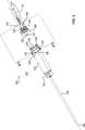
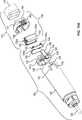
Bei dem Endoskop
Das Endoskop
Das Endoskop
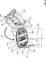
Die Endoskophülle
Zum Trennen des in der Kabelhülle
Das in der Kabelhülle
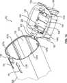
Die Endoskophülle
Die Endoskophülle
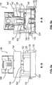
Der Steriladapter
Zum sterilen Abschirmen des Kabels
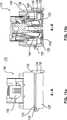
Wie in den
Beim Trennen der Steckverbinder
Der Operationstisch
Die Instrumenteneinheit
BezugszeichenlisteLIST OF REFERENCE NUMBERS
- 10, 10010, 100
- Anordnungarrangement
- 12, 11212, 112
- EndoskophülleThe endoscope sheath
- 14, 11414, 114
- Endoskopendoscope
- 16, 11616, 116
- Kabelhüllecable sheath
- 18, 111818, 1118
- Endoskopkabelendoscope cable
- 2020
- SteckverbinderConnectors
- 2626
- stabförmiger Bereichrod-shaped area
- 2828
- Spitzetop
- 3030
- optisches Elementoptical element
- 32, 13232, 132
- Endoskopkörperendoscope body
- 34, 3634, 36
- mechanisches Verbindungselementmechanical connection element
- 3838
- elektrischer Kontaktelectric contact
- 4040
- optisches Verbindungselementoptical connection element
- 42, 14242, 142
- Sterilschleusesterile lock
- 44, 46, 144, 146, 50, 52, 150, 15244, 46, 144, 146, 50, 52, 150, 152
- Sterilklappesterile flap
- 48, 14848, 148
- Steriladapter/SterilschleuseSterile Adapter / sterile lock
- 54, 5654, 56
- mechanisches Verbindungselementmechanical connection element
- 110110
- steriler Bereichsterile area
- 117 117
- offenes Endeopen end
- 125125
- Verschlusselementclosure element
- 126126
- stabförmiger Bereichrod-shaped area
- 127127
- Spitzetop
- 128128
- Mittelteil der EndoskophülleMiddle part of the endoscope skin
- 129129
- vorderer Teil der Endoskophüllefront part of the endoscope skin
- 130130
- optisches Elementoptical element
- 133133
- Scharnierhinge
- 134134
- RastverbinderRest connector
- 135135
- Eingriffselementengaging member
- 136136
- Zuführ- und EntnahmeöffnungFeed and removal opening
- 137a bis 137e137a to 137e
- Führungsstegeguide webs
- 138138
- Hybridsteckverbinderhybrid connector
- 139a bis 139d139a to 139d
- DistanzstifteStandoffs
- 154, 155154, 155
- RastverbinderRest connector
- 156156
- SteckverbinderConnectors
- 158, 160158, 160
- Betätigungselementactuator
- 162, 164162, 164
- Rastelementlocking element
- 144a, 146a, 150a, 152a144a, 146a, 150a, 152a
- Führungsstifteguide pins
- 144b, 146b144b, 146b
- Federfeather
- 165165
- Öffnungsspaltopening gap
- 166, 168166, 168
- Vertiefungdeepening
- 170170
- Rückseiteback
- 172172
- optischer Übertragungskanaloptical transmission channel
- 174174
- elektrisches Kontaktelementelectrical contact element
- 176176
- Gehäusecasing
- 178, 180178, 180
- Führungs- und VerriegelungsstifteGuide and locking pins
- 178a, 180a178a, 180a
- Vertiefungdeepening
- 182, 184182, 184
- Führungsbuchseguide bush
- 190, 192190, 192
- Rastelementlocking element
- 194, 196194, 196
- Eingriffsöffnungenengagement openings
- 200200
- optischer Übertragungskanaloptical transmission channel
- 202202
- elektrischer Kontaktelectric contact
- 204204
- Gehäusecasing
- 206, 208206, 208
- Rastelementelocking elements
- 206a, 208a206a, 208a
- Betätigungsbereichoperating range
- 210210
- Eingriffselementengaging member
- 212, 214, 216, 218212, 214, 216, 218
- Aufnahmebereichreception area
- 220220
- Führungsstiftguide pin
- 144b, 146b144b, 146b
- Federfeather
- P1 bis P12P1 to P12
- Richtungspfeiledirectional arrows
- 10001000
- Systemsystem
- 12001200
- Manipulatormanipulator
- 14001400
- Stativtripod
- 1600a bis 1600d1600a to 1600d
- Manipulatorarmmanipulator
- 18001800
- Patientpatient
- 20002000
- Stativkopftripod head
- 24002400
- Stativfußstand base
- 28002800
- Stativarmstand arm
- 30003000
- ZieloperationsgebietTarget area of operations
- 32003200
- OperationstischsäuleOperating table column
- 34003400
- Operationstischoperating table
- 36003600
- Steuereinheit des OperationstischesControl unit of the operating table
- 38003800
- PatientenlagerflächePatient support surface
- 40004000
- zentrale Steuereinheit der Vorrichtungcentral control unit of the device
- 41004100
- Ausgabeeinheitoutput unit
- 42004200
- Bedienkonsoleoperator
- 44004400
- Anzeigeeinheitdisplay unit
- 46004600
- Steuereinheit des ManipulatorsControl unit of the manipulator
- 47004700
- Ausgabeeinheitoutput unit
- 1100a bis 1100d1100a to 1100d
- Koppeleinheitcoupling unit
- 1300a bis 1300d1300a to 1300d
- Instrumenteneinheitinstrument unit
ZITATE ENTHALTEN IN DER BESCHREIBUNG QUOTES INCLUDE IN THE DESCRIPTION
Diese Liste der vom Anmelder aufgeführten Dokumente wurde automatisiert erzeugt und ist ausschließlich zur besseren Information des Lesers aufgenommen. Die Liste ist nicht Bestandteil der deutschen Patent- bzw. Gebrauchsmusteranmeldung. Das DPMA übernimmt keinerlei Haftung für etwaige Fehler oder Auslassungen.This list of the documents listed by the applicant has been generated automatically and is included solely for the better information of the reader. The list is not part of the German patent or utility model application. The DPMA assumes no liability for any errors or omissions.
Zitierte PatentliteraturCited patent literature
- DE 102010022429 A1[0002]DE 102010022429 A1[0002]
- WO 2012/075989 A1[0003]WO 2012/075989 A1[0003]
- DE 102012008535 A1[0004]DE 102012008535 A1[0004]
Claims (17)
Translated fromGermanPriority Applications (9)
| Application Number | Priority Date | Filing Date | Title |
|---|---|---|---|
| DE102016109601.6ADE102016109601A1 (en) | 2016-05-25 | 2016-05-25 | Arrangement for the sterile handling of non-sterile units in a sterile environment |
| HUE17730064AHUE051960T2 (en) | 2016-05-25 | 2017-05-23 | Arrangement for the sterile handling of non-sterile units in a sterile environment |
| CN201780032180.3ACN109195497B (en) | 2016-05-25 | 2017-05-23 | Device for sterile handling of non-sterile units in a sterile environment |
| PCT/EP2017/062379WO2017202831A1 (en) | 2016-05-25 | 2017-05-23 | Arrangement for the sterile handling of non-sterile units in a sterile environment |
| JP2018559970AJP6968102B2 (en) | 2016-05-25 | 2017-05-23 | Equipment for aseptic handling of non-sterile units in a sterile environment |
| RU2018145724ARU2741927C2 (en) | 2016-05-25 | 2017-05-23 | System for sterile handling of non-sterile instruments in a sterile environment |
| US16/303,740US11547282B2 (en) | 2016-05-25 | 2017-05-23 | Arrangement for the sterile handling of non-sterile units in a sterile environment |
| CA3025240ACA3025240A1 (en) | 2016-05-25 | 2017-05-23 | Arrangement for the sterile handling of non-sterile units in a sterile environment |
| EP17730064.7AEP3463034B1 (en) | 2016-05-25 | 2017-05-23 | Arrangement for the sterile handling of non-sterile units in a sterile environment |
Applications Claiming Priority (1)
| Application Number | Priority Date | Filing Date | Title |
|---|---|---|---|
| DE102016109601.6ADE102016109601A1 (en) | 2016-05-25 | 2016-05-25 | Arrangement for the sterile handling of non-sterile units in a sterile environment |
Publications (1)
| Publication Number | Publication Date |
|---|---|
| DE102016109601A1true DE102016109601A1 (en) | 2017-11-30 |
Family
ID=59061958
Family Applications (1)
| Application Number | Title | Priority Date | Filing Date |
|---|---|---|---|
| DE102016109601.6AWithdrawnDE102016109601A1 (en) | 2016-05-25 | 2016-05-25 | Arrangement for the sterile handling of non-sterile units in a sterile environment |
Country Status (9)
| Country | Link |
|---|---|
| US (1) | US11547282B2 (en) |
| EP (1) | EP3463034B1 (en) |
| JP (1) | JP6968102B2 (en) |
| CN (1) | CN109195497B (en) |
| CA (1) | CA3025240A1 (en) |
| DE (1) | DE102016109601A1 (en) |
| HU (1) | HUE051960T2 (en) |
| RU (1) | RU2741927C2 (en) |
| WO (1) | WO2017202831A1 (en) |
Cited By (25)
| Publication number | Priority date | Publication date | Assignee | Title |
|---|---|---|---|---|
| WO2021173861A1 (en)* | 2020-02-28 | 2021-09-02 | Bard Access Systems, Inc. | Optical connection systems and methods thereof |
| US11525670B2 (en) | 2019-11-25 | 2022-12-13 | Bard Access Systems, Inc. | Shape-sensing systems with filters and methods thereof |
| US11622816B2 (en) | 2020-06-26 | 2023-04-11 | Bard Access Systems, Inc. | Malposition detection system |
| US11624677B2 (en) | 2020-07-10 | 2023-04-11 | Bard Access Systems, Inc. | Continuous fiber optic functionality monitoring and self-diagnostic reporting system |
| US11630009B2 (en) | 2020-08-03 | 2023-04-18 | Bard Access Systems, Inc. | Bragg grated fiber optic fluctuation sensing and monitoring system |
| US11850338B2 (en) | 2019-11-25 | 2023-12-26 | Bard Access Systems, Inc. | Optical tip-tracking systems and methods thereof |
| US11883609B2 (en) | 2020-06-29 | 2024-01-30 | Bard Access Systems, Inc. | Automatic dimensional frame reference for fiber optic |
| US11899249B2 (en) | 2020-10-13 | 2024-02-13 | Bard Access Systems, Inc. | Disinfecting covers for functional connectors of medical devices and methods thereof |
| US11931112B2 (en) | 2019-08-12 | 2024-03-19 | Bard Access Systems, Inc. | Shape-sensing system and methods for medical devices |
| US11931179B2 (en) | 2020-03-30 | 2024-03-19 | Bard Access Systems, Inc. | Optical and electrical diagnostic systems and methods thereof |
| DE102023103175A1 (en)* | 2023-02-09 | 2024-08-14 | Karl Storz Se & Co. Kg | Endoscope, base module and handling module for an endoscope, sterile single-use product, system and method for providing an endoscope |
| US12064569B2 (en) | 2020-09-25 | 2024-08-20 | Bard Access Systems, Inc. | Fiber optics oximetry system for detection and confirmation |
| US12089815B2 (en) | 2022-03-17 | 2024-09-17 | Bard Access Systems, Inc. | Fiber optic medical systems and devices with atraumatic tip |
| US12140487B2 (en) | 2017-04-07 | 2024-11-12 | Bard Access Systems, Inc. | Optical fiber-based medical device tracking and monitoring system |
| US12220219B2 (en) | 2020-11-24 | 2025-02-11 | Bard Access Systems, Inc. | Steerable fiber optic shape sensing enabled elongated medical instrument |
| US12232818B2 (en) | 2020-03-03 | 2025-02-25 | Bard Access Systems, Inc. | System and method for optic shape sensing and electrical signal conduction |
| US12232821B2 (en) | 2021-01-06 | 2025-02-25 | Bard Access Systems, Inc. | Needle guidance using fiber optic shape sensing |
| US12246139B2 (en) | 2020-02-28 | 2025-03-11 | Bard Access Systems, Inc. | Catheter with optic shape sensing capabilities |
| US12285572B2 (en) | 2020-11-18 | 2025-04-29 | Bard Access Systems, Inc. | Optical-fiber stylet holders and methods thereof |
| US12318149B2 (en) | 2022-03-08 | 2025-06-03 | Bard Access Systems, Inc. | Medical shape sensing devices and systems |
| US12343117B2 (en) | 2022-06-28 | 2025-07-01 | Bard Access Systems, Inc. | Fiber optic medical systems and methods for identifying blood vessels |
| US12349984B2 (en) | 2022-06-29 | 2025-07-08 | Bard Access Systems, Inc. | System, method, and apparatus for improved confirm of an anatomical position of a medical instrument |
| US12419694B2 (en) | 2021-10-25 | 2025-09-23 | Bard Access Systems, Inc. | Reference plane for medical device placement |
| US12426956B2 (en) | 2022-03-16 | 2025-09-30 | Bard Access Systems, Inc. | Medical system and method for monitoring medical device insertion and illumination patterns |
| US12426954B2 (en) | 2021-01-26 | 2025-09-30 | Bard Access Systems, Inc. | Fiber optic shape sensing system associated with port placement |
Families Citing this family (24)
| Publication number | Priority date | Publication date | Assignee | Title |
|---|---|---|---|---|
| US10869592B2 (en) | 2015-02-23 | 2020-12-22 | Uroviu Corp. | Handheld surgical endoscope |
| DE102016109601A1 (en)* | 2016-05-25 | 2017-11-30 | avateramedical GmBH | Arrangement for the sterile handling of non-sterile units in a sterile environment |
| US11832797B2 (en) | 2016-09-25 | 2023-12-05 | Micronvision Corp. | Endoscopic fluorescence imaging |
| US11684248B2 (en) | 2017-09-25 | 2023-06-27 | Micronvision Corp. | Endoscopy/stereo colposcopy medical instrument |
| WO2018098465A1 (en) | 2016-11-28 | 2018-05-31 | Inventio, Inc. | Endoscope with separable, disposable shaft |
| US12268358B2 (en) | 2019-12-05 | 2025-04-08 | Uroviu Corp. | Portable endoscope with side-mountable disposable portion |
| US11771304B1 (en) | 2020-11-12 | 2023-10-03 | Micronvision Corp. | Minimally invasive endoscope |
| US11980342B2 (en)* | 2020-11-12 | 2024-05-14 | Micronvision Corp. | Minimally invasive endoscope |
| EP3737328B1 (en)* | 2018-01-09 | 2025-04-30 | Covidien LP | STERILE INTERFACE MODULE FOR ROBOTIC SURGICAL DEVICES |
| GB2570518B8 (en)* | 2018-01-30 | 2023-05-24 | Cmr Surgical Ltd | Interfacing a surgical robotic arm and instrument |
| EP3773128B1 (en)* | 2018-04-04 | 2023-07-19 | CooperSurgical, Inc. | Endoscopic devices and related methods |
| WO2020154596A1 (en)* | 2019-01-24 | 2020-07-30 | Noah Medical Corporation | Single use devices with integrated vision capabilities |
| CN110215180B (en)* | 2019-07-04 | 2024-06-07 | 上海安清医疗器械有限公司 | Rigid endoscope device |
| JP2022540882A (en) | 2019-07-15 | 2022-09-20 | ボストン サイエンティフィック サイムド,インコーポレイテッド | Medical systems, devices and related methods |
| EP4003138A4 (en) | 2019-07-25 | 2023-08-30 | Uroviu Corp. | DISPOSABLE ENDOSCOPY NEEDLE WITH INTEGRATED GRIPPER |
| USD1018844S1 (en) | 2020-01-09 | 2024-03-19 | Adaptivendo Llc | Endoscope handle |
| CN114431959B (en)* | 2020-10-30 | 2023-12-29 | 上海微创医疗机器人(集团)股份有限公司 | Isolation device and surgical robot system |
| USD1051380S1 (en) | 2020-11-17 | 2024-11-12 | Adaptivendo Llc | Endoscope handle |
| CN112716621B (en)* | 2021-01-20 | 2024-03-12 | 威海威高骨科手术机器人有限公司 | Sterile isolation and positioning device |
| JP7590217B2 (en)* | 2021-03-01 | 2024-11-26 | 矢崎総業株式会社 | connector |
| USD1031035S1 (en) | 2021-04-29 | 2024-06-11 | Adaptivendo Llc | Endoscope handle |
| USD1070082S1 (en) | 2021-04-29 | 2025-04-08 | Adaptivendo Llc | Endoscope handle |
| USD1066659S1 (en) | 2021-09-24 | 2025-03-11 | Adaptivendo Llc | Endoscope handle |
| WO2025057025A1 (en)* | 2023-09-11 | 2025-03-20 | Valuebiotech S.R.L. | Vision system for robotic surgery |
Citations (3)
| Publication number | Priority date | Publication date | Assignee | Title |
|---|---|---|---|---|
| DE102010022429A1 (en) | 2010-06-01 | 2011-12-01 | Karl Storz Gmbh & Co. Kg | Casing for image transfer device of video endoscope in medical field, has distal and proximal casing parts connected in releasable and fluid tight mechanical manner by sealing element and rotatable relative to each other |
| WO2012075989A1 (en) | 2010-12-08 | 2012-06-14 | Markus Friedrich | Hand-operated endoscope for medical purposes |
| DE102012008535A1 (en) | 2012-04-27 | 2013-10-31 | Kuka Laboratories Gmbh | Surgical robot system has instrument arrangement with instrument that is guided by robot, where degree of freedom of instrument shaft is actuated by drive train of drive train arrangement that is actuated by drive unit |
Family Cites Families (60)
| Publication number | Priority date | Publication date | Assignee | Title |
|---|---|---|---|---|
| US4176897A (en)* | 1976-11-19 | 1979-12-04 | Bunker Ramo Corporation | EMI protected connector assembly |
| US4217019A (en)* | 1976-11-19 | 1980-08-12 | Bunker Ramo Corporation | EMI protected connector assembly |
| US4345808A (en)* | 1980-11-20 | 1982-08-24 | International Telephone And Telegraph Corporation | Electrical connector |
| US4877033A (en)* | 1988-05-04 | 1989-10-31 | Seitz Jr H Michael | Disposable needle guide and examination sheath for transvaginal ultrasound procedures |
| US5168863A (en)* | 1990-08-27 | 1992-12-08 | Medical Concepts, Inc. | Sterile endoscopic system |
| JP2564223Y2 (en)* | 1991-06-04 | 1998-03-04 | 株式会社トップ | Valve body |
| JPH0528351A (en) | 1991-07-19 | 1993-02-05 | Fuji Electric Co Ltd | Structure for holding sample products in the display room of vending machines |
| US5554098A (en)* | 1993-02-26 | 1996-09-10 | Olympus Optical Co., Ltd. | Endoscope system including endoscope and disposable protection cover |
| US5792045A (en)* | 1994-10-03 | 1998-08-11 | Adair; Edwin L. | Sterile surgical coupler and drape |
| US5591119A (en)* | 1994-12-07 | 1997-01-07 | Adair; Edwin L. | Sterile surgical coupler and drape |
| US5695449A (en)* | 1995-04-18 | 1997-12-09 | Olympus Optical Co., Ltd. | Cover-sheathed endoscope |
| US5873814A (en)* | 1996-07-12 | 1999-02-23 | Adair; Edwin L. | Sterile encapsulated endoscopic video monitor and method |
| US5957831A (en)* | 1996-07-12 | 1999-09-28 | Adair; Edwin L. | Sterile encapsulated endoscopic video monitor |
| US7666191B2 (en)* | 1996-12-12 | 2010-02-23 | Intuitive Surgical, Inc. | Robotic surgical system with sterile surgical adaptor |
| US5876328A (en)* | 1997-04-23 | 1999-03-02 | Endolap, Inc. | Surgical camera drape assembly and method |
| US5980450A (en)* | 1997-05-07 | 1999-11-09 | Pinotage, Llc | Coupling device for use in an imaging system |
| AU2582699A (en)* | 1998-02-05 | 1999-08-23 | Alcoa Fujikura Limited | Fiber optic adapter shutter door assembly |
| WO2000039003A1 (en)* | 1998-12-30 | 2000-07-06 | Ethicon, Inc. | Sterile packaging for flexible endoscopes |
| DE29905355U1 (en)* | 1999-03-24 | 1999-07-08 | Olympus Winter & Ibe Gmbh, 22045 Hamburg | Medical endoscope with a video camera covered by a sterile tube |
| US8317689B1 (en)* | 1999-09-13 | 2012-11-27 | Visionscope Technologies Llc | Miniature endoscope system |
| US20020133058A1 (en)* | 2000-09-26 | 2002-09-19 | Calderwood Mitchell C. | Prophylactic cover and drape for endoscopic camera system |
| JP2002119517A (en)* | 2000-10-18 | 2002-04-23 | Olympus Optical Co Ltd | Endoscopic surgery device |
| JP4629260B2 (en)* | 2001-04-05 | 2011-02-09 | Hoya株式会社 | Endoscope cleaning device |
| US7160246B2 (en)* | 2002-10-17 | 2007-01-09 | Microtek Medical, Inc. | System and method for removing a protective cover from a medical instrument |
| US8019420B2 (en)* | 2003-08-21 | 2011-09-13 | Medtronic, Inc. | Medical lead connector systems with adapters |
| US20050101838A1 (en)* | 2003-11-12 | 2005-05-12 | Camillocci Philip L. | Endoscope cover |
| US7803109B2 (en)* | 2004-04-16 | 2010-09-28 | Ricardo Alexander Gomez | Method and apparatus for protecting the distal lens of endoscopes |
| JP2007097767A (en)* | 2005-10-03 | 2007-04-19 | Olympus Corp | Electron endoscope system |
| EP1772104A2 (en)* | 2005-10-07 | 2007-04-11 | Tsion Israel Medical Systems Ltd. | Contamination protection device and method for use |
| CA2854625C (en)* | 2006-01-27 | 2017-01-24 | Suturtek Incorporated | Apparatus and method for tissue closure |
| US20070185383A1 (en)* | 2006-02-08 | 2007-08-09 | Vision-Sciences, Inc. | Tapered endoscopic protective sheath |
| FR2899087B1 (en)* | 2006-04-03 | 2008-06-20 | V I M S Video Interventionnell | PROTECTION FOR ENDOSCOPE AND CORRESPONDING ENDOSCOPE |
| ITMI20070544A1 (en)* | 2007-03-20 | 2008-09-21 | F A R O Fabbrica Apparecchiatur | IMPROVED DEVICE FOR DENTAL INTERVENTIONS |
| DE102007026235A1 (en)* | 2007-05-31 | 2008-12-04 | Karl Storz Gmbh & Co. Kg | Device for the sterile enclosure of a sterilization-sensitive control panel |
| JP5000549B2 (en)* | 2008-02-27 | 2012-08-15 | オリンパスメディカルシステムズ株式会社 | Electrical connector |
| FR2934423B1 (en)* | 2008-07-24 | 2010-08-20 | Sagem Defense Securite | DEVICE FOR PROTECTING THE EMBOITABLE ELEMENTS OF A CONNECTOR |
| US20100234733A1 (en)* | 2009-03-13 | 2010-09-16 | Paul Wahlheim | Sterile Ultrasound Probe Cover and Method of Releasing Coupling Agent from a Sealed Compartment |
| US20120010468A1 (en)* | 2010-07-06 | 2012-01-12 | Adel Afridi | System of disposable contoured sleeves for flexible endoscopes |
| WO2012097181A1 (en)* | 2011-01-12 | 2012-07-19 | King Systems Corporation | Visualization instrument |
| DE102012207060A1 (en) | 2012-04-27 | 2013-10-31 | Deutsches Zentrum für Luft- und Raumfahrt e.V. | Robot assembly for use in medical fields |
| CN104586510B (en)* | 2012-04-27 | 2018-10-02 | 库卡实验仪器有限公司 | Robotic surgical system |
| CN104379045B (en)* | 2012-06-07 | 2016-11-23 | 皇家飞利浦有限公司 | There is optics connect and the medical science adapter rinsed of electrical connection |
| WO2014014475A1 (en)* | 2012-07-20 | 2014-01-23 | Acist Medical Systems, Inc. | Connector cover for protecting a connection from contaminants |
| US8910637B2 (en)* | 2012-12-12 | 2014-12-16 | Marilyn Winer | Sterile drape for robotic surgical equipment |
| CA2836223A1 (en)* | 2012-12-17 | 2014-06-17 | Gerald Gestetner | Endoscope sheath |
| US20160000507A1 (en)* | 2013-02-13 | 2016-01-07 | Biolitec Pharma Marketing Ltd. | Enclosed laser medical device/system |
| ITMI20130516A1 (en) | 2013-04-05 | 2014-10-06 | Sofar Spa | SURGICAL SYSTEM WITH STERILE TOWELS |
| US20150094713A1 (en)* | 2013-09-30 | 2015-04-02 | Covidien Lp | Systems and methods for electrical coupling in a medical device |
| US20150202009A1 (en)* | 2014-01-22 | 2015-07-23 | KB Medical SA | Sterile drape and adapter for covering a robotic surgical arm and preventing contamination of a sterile field |
| WO2015191954A1 (en)* | 2014-06-12 | 2015-12-17 | Endoluxe Inc. | Encasement platform for smartdevice for attachment to endoscope |
| GB201412910D0 (en)* | 2014-07-21 | 2014-09-03 | Creo Medical Ltd | Electrical connector for an electrosurgical apparatus |
| DE102014117407A1 (en)* | 2014-11-27 | 2016-06-02 | avateramedical GmBH | Device for robotic surgery |
| US20160174821A1 (en)* | 2014-12-22 | 2016-06-23 | Heidi Homze | Disposable Protective Sleeve for Equine Endoscope |
| DE102015109371A1 (en)* | 2015-06-12 | 2016-12-15 | avateramedical GmBH | Apparatus and method for robotic surgery |
| DE102015109368A1 (en)* | 2015-06-12 | 2016-12-15 | avateramedical GmBH | Device and method for robotic surgery and positioning aid |
| DE102015119695A1 (en)* | 2015-11-13 | 2017-05-18 | Xion Gmbh | sterile adapter |
| US20170209027A1 (en)* | 2016-01-26 | 2017-07-27 | Muruga Raj | Measurement device |
| US11369450B2 (en)* | 2016-05-20 | 2022-06-28 | Intuitive Surgical Operations, Inc. | Instrument drape |
| DE102016109601A1 (en)* | 2016-05-25 | 2017-11-30 | avateramedical GmBH | Arrangement for the sterile handling of non-sterile units in a sterile environment |
| US20190167078A1 (en)* | 2017-12-04 | 2019-06-06 | Ethicon, Inc. | Sterilization package |
- 2016
- 2016-05-25DEDE102016109601.6Apatent/DE102016109601A1/ennot_activeWithdrawn
- 2017
- 2017-05-23CACA3025240Apatent/CA3025240A1/enactivePending
- 2017-05-23RURU2018145724Apatent/RU2741927C2/enactive
- 2017-05-23CNCN201780032180.3Apatent/CN109195497B/ennot_activeExpired - Fee Related
- 2017-05-23JPJP2018559970Apatent/JP6968102B2/ennot_activeExpired - Fee Related
- 2017-05-23EPEP17730064.7Apatent/EP3463034B1/ennot_activeNot-in-force
- 2017-05-23HUHUE17730064Apatent/HUE051960T2/enunknown
- 2017-05-23USUS16/303,740patent/US11547282B2/enactiveActive
- 2017-05-23WOPCT/EP2017/062379patent/WO2017202831A1/ennot_activeCeased
Patent Citations (3)
| Publication number | Priority date | Publication date | Assignee | Title |
|---|---|---|---|---|
| DE102010022429A1 (en) | 2010-06-01 | 2011-12-01 | Karl Storz Gmbh & Co. Kg | Casing for image transfer device of video endoscope in medical field, has distal and proximal casing parts connected in releasable and fluid tight mechanical manner by sealing element and rotatable relative to each other |
| WO2012075989A1 (en) | 2010-12-08 | 2012-06-14 | Markus Friedrich | Hand-operated endoscope for medical purposes |
| DE102012008535A1 (en) | 2012-04-27 | 2013-10-31 | Kuka Laboratories Gmbh | Surgical robot system has instrument arrangement with instrument that is guided by robot, where degree of freedom of instrument shaft is actuated by drive train of drive train arrangement that is actuated by drive unit |
Cited By (36)
| Publication number | Priority date | Publication date | Assignee | Title |
|---|---|---|---|---|
| US12140487B2 (en) | 2017-04-07 | 2024-11-12 | Bard Access Systems, Inc. | Optical fiber-based medical device tracking and monitoring system |
| US11931112B2 (en) | 2019-08-12 | 2024-03-19 | Bard Access Systems, Inc. | Shape-sensing system and methods for medical devices |
| US11850338B2 (en) | 2019-11-25 | 2023-12-26 | Bard Access Systems, Inc. | Optical tip-tracking systems and methods thereof |
| US11525670B2 (en) | 2019-11-25 | 2022-12-13 | Bard Access Systems, Inc. | Shape-sensing systems with filters and methods thereof |
| US12130127B2 (en) | 2019-11-25 | 2024-10-29 | Bard Access Systems, Inc. | Shape-sensing systems with filters and methods thereof |
| US12403288B2 (en) | 2019-11-25 | 2025-09-02 | Bard Access Systems, Inc. | Optical tip-tracking systems and methods thereof |
| US12246139B2 (en) | 2020-02-28 | 2025-03-11 | Bard Access Systems, Inc. | Catheter with optic shape sensing capabilities |
| US11638536B1 (en) | 2020-02-28 | 2023-05-02 | Bard Access Systems, Inc. | Optical connection systems and methods thereof |
| US12287520B2 (en) | 2020-02-28 | 2025-04-29 | Bard Access Systems, Inc. | Optical connection systems and methods thereof |
| WO2021173861A1 (en)* | 2020-02-28 | 2021-09-02 | Bard Access Systems, Inc. | Optical connection systems and methods thereof |
| US11474310B2 (en) | 2020-02-28 | 2022-10-18 | Bard Access Systems, Inc. | Optical connection systems and methods thereof |
| US12232818B2 (en) | 2020-03-03 | 2025-02-25 | Bard Access Systems, Inc. | System and method for optic shape sensing and electrical signal conduction |
| US12376794B2 (en) | 2020-03-30 | 2025-08-05 | Bard Access Systems, Inc. | Optical and electrical diagnostic systems and methods thereof |
| US11931179B2 (en) | 2020-03-30 | 2024-03-19 | Bard Access Systems, Inc. | Optical and electrical diagnostic systems and methods thereof |
| US12390283B2 (en) | 2020-06-26 | 2025-08-19 | Bard Access Systems, Inc. | Malposition detection system |
| US11622816B2 (en) | 2020-06-26 | 2023-04-11 | Bard Access Systems, Inc. | Malposition detection system |
| US12397131B2 (en) | 2020-06-29 | 2025-08-26 | Bard Access Systems, Inc. | Automatic dimensional frame reference for fiber optic |
| US11883609B2 (en) | 2020-06-29 | 2024-01-30 | Bard Access Systems, Inc. | Automatic dimensional frame reference for fiber optic |
| US12264996B2 (en) | 2020-07-10 | 2025-04-01 | Bard Access Systems, Inc. | Continuous fiber optic functionality monitoring and self-diagnostic reporting system |
| US11624677B2 (en) | 2020-07-10 | 2023-04-11 | Bard Access Systems, Inc. | Continuous fiber optic functionality monitoring and self-diagnostic reporting system |
| US12038338B2 (en) | 2020-08-03 | 2024-07-16 | Bard Access Systems, Inc. | Bragg grated fiber optic fluctuation sensing and monitoring system |
| US11630009B2 (en) | 2020-08-03 | 2023-04-18 | Bard Access Systems, Inc. | Bragg grated fiber optic fluctuation sensing and monitoring system |
| US12064569B2 (en) | 2020-09-25 | 2024-08-20 | Bard Access Systems, Inc. | Fiber optics oximetry system for detection and confirmation |
| US12181720B2 (en) | 2020-10-13 | 2024-12-31 | Bard Access Systems, Inc. | Disinfecting covers for functional connectors of medical devices and methods thereof |
| US11899249B2 (en) | 2020-10-13 | 2024-02-13 | Bard Access Systems, Inc. | Disinfecting covers for functional connectors of medical devices and methods thereof |
| US12285572B2 (en) | 2020-11-18 | 2025-04-29 | Bard Access Systems, Inc. | Optical-fiber stylet holders and methods thereof |
| US12220219B2 (en) | 2020-11-24 | 2025-02-11 | Bard Access Systems, Inc. | Steerable fiber optic shape sensing enabled elongated medical instrument |
| US12232821B2 (en) | 2021-01-06 | 2025-02-25 | Bard Access Systems, Inc. | Needle guidance using fiber optic shape sensing |
| US12426954B2 (en) | 2021-01-26 | 2025-09-30 | Bard Access Systems, Inc. | Fiber optic shape sensing system associated with port placement |
| US12419694B2 (en) | 2021-10-25 | 2025-09-23 | Bard Access Systems, Inc. | Reference plane for medical device placement |
| US12318149B2 (en) | 2022-03-08 | 2025-06-03 | Bard Access Systems, Inc. | Medical shape sensing devices and systems |
| US12426956B2 (en) | 2022-03-16 | 2025-09-30 | Bard Access Systems, Inc. | Medical system and method for monitoring medical device insertion and illumination patterns |
| US12089815B2 (en) | 2022-03-17 | 2024-09-17 | Bard Access Systems, Inc. | Fiber optic medical systems and devices with atraumatic tip |
| US12343117B2 (en) | 2022-06-28 | 2025-07-01 | Bard Access Systems, Inc. | Fiber optic medical systems and methods for identifying blood vessels |
| US12349984B2 (en) | 2022-06-29 | 2025-07-08 | Bard Access Systems, Inc. | System, method, and apparatus for improved confirm of an anatomical position of a medical instrument |
| DE102023103175A1 (en)* | 2023-02-09 | 2024-08-14 | Karl Storz Se & Co. Kg | Endoscope, base module and handling module for an endoscope, sterile single-use product, system and method for providing an endoscope |
Also Published As
| Publication number | Publication date |
|---|---|
| HUE051960T2 (en) | 2021-03-29 |
| RU2018145724A (en) | 2020-06-25 |
| EP3463034A1 (en) | 2019-04-10 |
| CN109195497B (en) | 2021-10-12 |
| WO2017202831A1 (en) | 2017-11-30 |
| CN109195497A (en) | 2019-01-11 |
| US11547282B2 (en) | 2023-01-10 |
| RU2741927C2 (en) | 2021-01-29 |
| JP6968102B2 (en) | 2021-11-17 |
| RU2018145724A3 (en) | 2020-08-25 |
| JP2019521729A (en) | 2019-08-08 |
| CA3025240A1 (en) | 2017-11-30 |
| US20200275827A1 (en) | 2020-09-03 |
| EP3463034B1 (en) | 2020-04-01 |
Similar Documents
| Publication | Publication Date | Title |
|---|---|---|
| EP3463034B1 (en) | Arrangement for the sterile handling of non-sterile units in a sterile environment | |
| EP3025667B1 (en) | Device for robotic surgery | |
| EP3223738B1 (en) | Device for robot-assisted surgery | |
| EP3103410B1 (en) | Device and method for robot-assisted surgery | |
| DE102006059165B4 (en) | Sterile surgical adapter and coupling procedure | |
| EP1164917B1 (en) | Device for intracorporeal, minimal invasive treatment of a patient | |
| EP3017748B1 (en) | Adapter for endoscopy | |
| EP2850996B1 (en) | Device for taking a picture of an object field on a human or animal body | |
| DE102015109368A1 (en) | Device and method for robotic surgery and positioning aid | |
| WO2010028701A1 (en) | Laparoscope having adjustable shaft | |
| DE102013211698B4 (en) | Endoabdominal camera system | |
| EP1056399A1 (en) | Instrument used for endoscopic interventions | |
| WO2011044878A1 (en) | Endoscope | |
| DE19813383A1 (en) | Device with a transmitter unit, via which the position of a medical instrument can be detected in the context of a CAS system | |
| EP2841003A1 (en) | Robotic arrangement for use in medical fields | |
| WO2009024107A1 (en) | Modular endoscope | |
| DE102010053814A1 (en) | Endoscope for medical purposes | |
| DE102009025013B4 (en) | Automated instrument replacement system for minimally invasive surgery | |
| EP3565449A1 (en) | Medical mechatronic male and female interface device | |
| DE102020100677B3 (en) | Optical observation instrument | |
| DE102020106817A1 (en) | Docking device, surgical fixture and method | |
| DE4238977C2 (en) | Device for illuminating and inspecting cavities and spaces | |
| DE102015114742B4 (en) | Kinematics for an intracorporeally driven instrument of an endoscope | |
| DE102008046463B4 (en) | Laparoscope with rigid shaft and laparoscopic system | |
| WO2024165635A1 (en) | Medical imaging instrument, connector, system and method for operating a medical imaging instrument |
Legal Events
| Date | Code | Title | Description |
|---|---|---|---|
| R163 | Identified publications notified | ||
| R119 | Application deemed withdrawn, or ip right lapsed, due to non-payment of renewal fee |